EP4574413A1 - Press tool - Google Patents
Press tool Download PDFInfo
- Publication number
- EP4574413A1 EP4574413A1 EP23219661.8A EP23219661A EP4574413A1 EP 4574413 A1 EP4574413 A1 EP 4574413A1 EP 23219661 A EP23219661 A EP 23219661A EP 4574413 A1 EP4574413 A1 EP 4574413A1
- Authority
- EP
- European Patent Office
- Prior art keywords
- target
- contact point
- distance
- section
- spacer element
- Prior art date
- Legal status (The legal status is an assumption and is not a legal conclusion. Google has not performed a legal analysis and makes no representation as to the accuracy of the status listed.)
- Granted
Links
Images




Classifications
-
- B—PERFORMING OPERATIONS; TRANSPORTING
- B22—CASTING; POWDER METALLURGY
- B22F—WORKING METALLIC POWDER; MANUFACTURE OF ARTICLES FROM METALLIC POWDER; MAKING METALLIC POWDER; APPARATUS OR DEVICES SPECIALLY ADAPTED FOR METALLIC POWDER
- B22F3/00—Manufacture of workpieces or articles from metallic powder characterised by the manner of compacting or sintering; Apparatus specially adapted therefor ; Presses and furnaces
- B22F3/02—Compacting only
- B22F3/03—Press-moulding apparatus therefor
-
- B—PERFORMING OPERATIONS; TRANSPORTING
- B28—WORKING CEMENT, CLAY, OR STONE
- B28B—SHAPING CLAY OR OTHER CERAMIC COMPOSITIONS; SHAPING SLAG; SHAPING MIXTURES CONTAINING CEMENTITIOUS MATERIAL, e.g. PLASTER
- B28B3/00—Producing shaped articles from the material by using presses; Presses specially adapted therefor
- B28B3/02—Producing shaped articles from the material by using presses; Presses specially adapted therefor wherein a ram exerts pressure on the material in a moulding space; Ram heads of special form
- B28B3/028—Centering the press head, e.g. using guiding pins or chamfered mould edges
-
- B—PERFORMING OPERATIONS; TRANSPORTING
- B28—WORKING CEMENT, CLAY, OR STONE
- B28B—SHAPING CLAY OR OTHER CERAMIC COMPOSITIONS; SHAPING SLAG; SHAPING MIXTURES CONTAINING CEMENTITIOUS MATERIAL, e.g. PLASTER
- B28B3/00—Producing shaped articles from the material by using presses; Presses specially adapted therefor
- B28B3/02—Producing shaped articles from the material by using presses; Presses specially adapted therefor wherein a ram exerts pressure on the material in a moulding space; Ram heads of special form
- B28B3/08—Producing shaped articles from the material by using presses; Presses specially adapted therefor wherein a ram exerts pressure on the material in a moulding space; Ram heads of special form with two or more rams per mould
-
- B—PERFORMING OPERATIONS; TRANSPORTING
- B30—PRESSES
- B30B—PRESSES IN GENERAL
- B30B11/00—Presses specially adapted for forming shaped articles from material in particulate or plastic state, e.g. briquetting presses, tabletting presses
- B30B11/007—Presses specially adapted for forming shaped articles from material in particulate or plastic state, e.g. briquetting presses, tabletting presses using a plurality of pressing members working in different directions
-
- B—PERFORMING OPERATIONS; TRANSPORTING
- B30—PRESSES
- B30B—PRESSES IN GENERAL
- B30B11/00—Presses specially adapted for forming shaped articles from material in particulate or plastic state, e.g. briquetting presses, tabletting presses
- B30B11/02—Presses specially adapted for forming shaped articles from material in particulate or plastic state, e.g. briquetting presses, tabletting presses using a ram exerting pressure on the material in a moulding space
-
- B—PERFORMING OPERATIONS; TRANSPORTING
- B30—PRESSES
- B30B—PRESSES IN GENERAL
- B30B15/00—Details of, or accessories for, presses; Auxiliary measures in connection with pressing
- B30B15/02—Dies; Inserts therefor; Mounting thereof; Moulds
- B30B15/026—Mounting of dies, platens or press rams
-
- B—PERFORMING OPERATIONS; TRANSPORTING
- B30—PRESSES
- B30B—PRESSES IN GENERAL
- B30B15/00—Details of, or accessories for, presses; Auxiliary measures in connection with pressing
- B30B15/06—Platens or press rams
- B30B15/068—Drive connections, e.g. pivotal
-
- B—PERFORMING OPERATIONS; TRANSPORTING
- B22—CASTING; POWDER METALLURGY
- B22F—WORKING METALLIC POWDER; MANUFACTURE OF ARTICLES FROM METALLIC POWDER; MAKING METALLIC POWDER; APPARATUS OR DEVICES SPECIALLY ADAPTED FOR METALLIC POWDER
- B22F5/00—Manufacture of workpieces or articles from metallic powder characterised by the special shape of the product
- B22F2005/001—Cutting tools, earth boring or grinding tool other than table ware
Definitions
- the present invention relates to a press tool for forming, by compacting a powder, a cutting insert green body.
- a conventional method for producing a cutting insert for metal cutting is to form a green body by compressing a powder in a press tool.
- a powder is filled into a cavity and compacted by a punch, which is movable along a punch axis toward the cavity.
- press burr forms on the green body where it had contact with the outer edge of the punch.
- Such press burr is problematic when it is not evenly distributed around the edge of the green body.
- the width and dimension of the burr is different at different sides of the green body.
- the green body is sintered to form a cutting insert, and the edge is treated to form a cutting edge.
- the varying dimensions of the press burr may cause variation in the geometry of the cutting edge, which may affect the performance of the finished insert negatively.
- An inventive press tool for forming, by compacting a powder, a cutting insert green body comprises
- the press tool comprises at least one punch device.
- the press tool may comprise several punch devices arranged next to each other, concentrical to each other or opposed to each other, for example.
- Each punch device is operable to move along a punch axis toward the cavity for compacting powder therein.
- the press tool comprises two punch devices, arranged on opposing sides of the cavity such that, when they are operated to move along their respective punch axes toward the cavity, the cavity is closed and powder therein is compacted.
- the front section is comprised in an exchangeable punch tool.
- the punch tool typically comprises a coupling part, which, together with a complementary coupling part comprised in the punch device, forms a coupling.
- the coupling securely holds the punch tool so that a stable and strong punch device is achieved.
- the coupling which comprises both coupling parts, is comprised in the rear section, why the front section is a section axially forward of the complementary coupling part.
- the joint unit is configured as a separate component functioning as hinge or a sliding joint such as a ball joint.
- the joint units may comprise an elastic element, for example a spring, to provide the bias toward the start state.
- a rear portion of the rear section and/or a rear portion of the arm member are parts of or constitute the joint unit.
- the joint unit comprises a primary region at the rear section, which primary region is elastic.
- the joint unit comprises in addition a secondary region in form of a portion of the arm member, which secondary region is elastic.
- the joint unit may comprise a flange, which, with respect to the central longitudinal axis, extends radially outward from the rear section.
- the arm member extends axially forward from a radial outer portion of the flange.
- the primary region is a region comprising a portion of the rear section and optionally a portion of the flange.
- the secondary region is a region comprising a portion of the arm member and/or a portion of the flange, for example a radially outer portion of the flange and/or a rear portion of the arm member.
- the secondary region in the target state of the joint unit, has a smaller bending stiffness than the primary region.
- the secondary region has a smaller elastic deformation stiffness than the primary region. This is for example achievable by providing the rear portion of the arm member with smaller dimensions than the primary region of the joint unit at the rear section and/or the flange. Examples of further design alternatives are to provide the secondary region at the arm member in a material that is more elastic than the primary region at the rear section, and or, spring elements comprised in the joint unit may be correspondingly adapted.
- the rear section may advantageously be arranged to flex just enough for the front section to reach the target orientation, so that the punch device is not unnecessarily weakened.
- the front section is operable to assume a start orientation and a target orientation.
- the target orientation differs from the start orientation in that the front section is rotated around the punch axis, wherein the front point is in the same position both in the start orientation and in the target orientation, and/or the target orientation differs from the start orientation in that the front point of the front section is moved in a radial direction or in a combination thereof.
- the target orientation of the front section is achieved by changing the distance measured from the arm contact point to the rear contact point such that the rear section pivots, rotates and/or bends at the joint unit. Thereby the joint unit is forced into the target state.
- the position of the front point when the front section is in the target orientation is located a front target distance from the position of the front point when the front section is in the start orientation.
- problems with formation of unevenly distributed press burr may be caused by misalignment of the front section with the cavity and/or an angular error of the front section relative the cavity.
- specifically unevenly distributed press burr due to misalignment are correctable by a translational movement of the front point.
- the translation may be in any direction in the axial plane, for example in a radial direction, along an arc around the front point when the front section is in the start orientation, or both.
- the press tool comprises a spacer element that is operable to translate from a start position to a target position.
- the spacer element is a one piece component, for example a screw, a wedge, clamp or a lever.
- the spacer element is arranged and configured to engage the arm member via an arm contact point and the rear section via a rear contact point at least when it is in the target position.
- the spacer element is unengaged with at least one of the arm contact point and the rear contact point when the spacer element is in the start position.
- the front section reverts to the start orientation, which may be used to define a reference orientation of the front section and/or a reference position of the front point.
- the start state of the joint unit is the relaxed state.
- the portion is located axially behind the arm contact point.
- the spacer element is in direct contact with the arm contact point and/or the rear contact point, or through an intermediate element, for example a spring element.
- the spacer element is arranged between the arm member and the rear section.
- the arm contact point is located on a surface facing the rear section, and the rear contact point is located on a surface facing the arm member.
- the spacer element may directly engage the contact points by abutting against them and changing the distance between them by forcing them away from or toward each other.
- the spacer element when operated to translate from the start position to the target position, is arranged to force the arm contact point and the rear contact point away from each other such that the distance increases.
- the spacer element is arranged to decrease the distance when operated to translate from the start position to the target position.
- the arm member comprises a threaded through hole
- the screw is in threaded engagement with the thread in the through hole
- the arm contact point is located on the thread of the through hole.
- moving the spacer element corresponds to rotating the screw, whereby an operator is able to control the spacer target distance exactly.
- the arm contact point is located on a main surface of the arm member, or on an element that cooperates with the arm member.
- the spacer element when the spacer element is in the start position, the spacer element is in engagement with the arm contact point and the rear contact point, and the start state of the joint unit is the relaxed state, and, when the spacer element is in the target position, the spacer element has translated a spacer target distance, and wherein a ratio between the spacer target distance and the front target distance is at least 20.
- the target distance associated with the spacer element is to be understood as the linear distance an operator moves the spacer element in order to change the distance from the arm contact point to the rear contact point.
- the rear contact point is located at or close to the front end of the rear section.
- the rear section functions as a long lever creating a torque at the joint unit in response to a relatively large displacement at the rear contact point.
- the coupling at the front end contains sensitive reference surfaces, why, thanks to that the rear contact point is located on the abutment element, it is ensured that the spacer element does not push against the coupling even though it is located at the front end of the rear section. The risk of misalignment and/or deformation at the coupling caused by the spacer element is reduced.
- the abutment element is a sleeve element extending concentrically with the punch axis, which sleeve element has flexible walls, for example elastically deformable walls.
- the sleeve element is attached to the front end of the rear section axially rearward of the coupling and extend axially forward therefrom. Thanks to the flexible walls, the target distance of the spacer element is increased as compared to when the rear contact point is located on a non-flexible surface, which is advantageous for fine tuning the target position of the front section.
- the press tool further comprises a spring element, which is in engagement with the spacer element in a first end and with the rear contact point of the rear section with a second end.
- the spring element is an elastic element, for example a block of elastic material, a helical spring, a disk spring, a leaf springs, or similar.
- the press tool furthermore comprises
- the press tool may be configured to allow the target orientation of the front section to be adjusted in different linear directions and/or angular directions.
- the plurality of arm members are sperate elements or an integral element, wherein arm contact pints are located on different position for the respective arm member of the plurality of arm members.
- the plurality of spacer elements are sperate elements or an integral element.
- each spacer element is movable arranged independent from all other spacer elements.
- the joint unit comprises regions and/or elements, which each is associated with a respective one of the plurality of the arm members.
- the associated rear target distances have a different direction.
- the different rear target distances translate to associated different target orientations of the front section.
- the plurality of the spacer element comprises two spacer elements
- the plurality of the arm members comprises two associated arm members, wherein the target distances are arranged perpendicular relative each other.
- a first associated rear target distance and a first associated front target distance are perpendicular to a second associated rear target distance and second associated front target distance, respectively.
- the first associated rear target distance and the first associated front target distance are aligned and opposite to a third associated rear target distance and third associated front target distance, respectively.
- the first and second spacer elements operated in opposing pairs.
- the press tool comprises two pairs, i.e. four spacer elements. Thereby, fine tuning of the target orientation of the front section is simplified.
- the press tool is a split-die press tool and comprises two die sections 1, 2.
- the press tool further comprises two punch devices 3, 4 in form of a single upper punch device 3 and a single lower punch device 4.
- each of the die sections 1, 2 and each of the punch devices 3, 4 are individually movable.
- the die sections 1, 2 and the lower punch device 4 are moved to their respective proximal positions, whereby a closed cavity for compacting a powder therein is formed at the centre.
Landscapes
- Engineering & Computer Science (AREA)
- Mechanical Engineering (AREA)
- Manufacturing & Machinery (AREA)
- Chemical & Material Sciences (AREA)
- Ceramic Engineering (AREA)
- Forging (AREA)
- Dental Tools And Instruments Or Auxiliary Dental Instruments (AREA)
Abstract
Description
- The present invention relates to a press tool for forming, by compacting a powder, a cutting insert green body.
- A conventional method for producing a cutting insert for metal cutting is to form a green body by compressing a powder in a press tool. Typically, a powder is filled into a cavity and compacted by a punch, which is movable along a punch axis toward the cavity.
- When pressing such green bodies, it is common that press burr forms on the green body where it had contact with the outer edge of the punch. Such press burr is problematic when it is not evenly distributed around the edge of the green body. For example, the width and dimension of the burr is different at different sides of the green body. Later in the process, the green body is sintered to form a cutting insert, and the edge is treated to form a cutting edge. The varying dimensions of the press burr may cause variation in the geometry of the cutting edge, which may affect the performance of the finished insert negatively.
- It is an object of the present invention to at least partly obviate the above mentioned problem. This object is achieved according to the invention by means of a press tool according to claim 1.
- An inventive press tool for forming, by compacting a powder, a cutting insert green body, comprises
- a cavity for receiving the powder to be compacted, and
- a punch device, which is movably arranged along a punch axis for compressing the powder in the cavity, wherein the punch axis defines an axial direction and axial planes,
- an axially extending front section with a front end at the cavity, which front section is operable to assume a start orientation and a target orientation, and
- an axially extending rear section, which is connected with and located axially rearward of the front section,
- a movably arranged spacer element, wherein the spacer element is operable to translate from a start position to a target position,
- an arm member, which extends axially along the rear section at a distance therefrom, and
- a joint unit,
- the joint unit, which connects the arm member and the rear section such that the distance from the rear section to the arm member, in a position axially in front of the joint unit, is adjustable,
- the spacer element is arranged and configured to engage the arm member via an arm contact point and the rear section via a rear contact point,
- when the spacer element is in the start position, as seen in an axial projection on an axial plane, the distance from the arm contact point to the rear contact point is a rear start distance, whereby the joint unit is in a start state and the front section is in the start orientation, and,
- when the spacer element is in the target position, as seen in an axial projection on an axial plane, the distance from the arm contact point to the rear contact point is a rear target distance, whereby the joint unit is in a target state biased toward the start state and the front section is in the target orientation.
- It has been discovered that a reason for uneven burr is misalignment of the cavity or the punch, or manufacturing inaccuracies of the cavity and/or the punch. Thanks to the provision of the arm member, the joint unit and the spacer element, it is possible to reorient the front section of the punch device sideways or rotationally. The spacer element is operated to adjust the distance between the arm member and the rear section of the punch device by tilting or rotating an axis of the front section of the punch device. Thereby, the front section assumes the target orientation. Furthermore, by selecting the start orientation of the front section as a reference orientation, thanks to the bias of the joint unit, it is possible to revert to this orientation by simply moving the spacer element back to the start position thereof.
- The press tool according to the present invention is suitable for forming a cutting insert green body by compacting a powder, such as cermet, cemented carbide powder or a metallurgical powder. After the finished cutting insert green body has been formed and removed from the press tool, it may be subjected to other treatments such as sintering, grinding, edge treatment and/or coating. A cutting insert may be obtained from the cutting insert green body and used for machining, for example metal cutting. Examples of such cutting inserts are milling cutting inserts, turning cutting inserts and drilling cutting inserts. Preferably the inserts are later used for chip removing metal cutting.
- The press tool according to the present invention may be of any suitable kind. Preferably, the press tool comprises a die which forms a cavity. The press tool may be a so-called split-die press tool, wherein the die comprises several movable parts, for example two or four. A space defined by the parts of the die in their proximal, closed position constitutes the cavity.
- The press tool comprises at least one punch device. The press tool may comprise several punch devices arranged next to each other, concentrical to each other or opposed to each other, for example. Each punch device is operable to move along a punch axis toward the cavity for compacting powder therein. According to an embodiment, the press tool comprises two punch devices, arranged on opposing sides of the cavity such that, when they are operated to move along their respective punch axes toward the cavity, the cavity is closed and powder therein is compacted.
- The punch axis may coincide with a central longitudinal axis of the front section of the punch device, for example when the front section is in the start orientation. Alternatively, in the start orientation of the front section, the longitudinal axis of the front section is parallel to or inclined relative the punch axis. According to an embodiment, the punch axis is a vertical axis during normal operation.
- The punch axis defines a forward direction toward the cavity and an opposite, rearward direction, and axial planes. Each axial plane is located in a respective position along the punch axis and has the punch axis as normal. An axial projection of a point on an axial plane, is to be understood as an imaginary movement of the point parallel to the punch axis to the axial plane in question. When a distance from a first point to a second point as seen in an axial projection on an axial plane is measured, both points are axially projected on the same axial plane and the distance between them is measured from the first point to the second point in that plane.
- A distance is to be understood as a linear distance. The path of travel of a relevant point or component may be a linear path, or deviate therefrom, for example by being an arc or curve in a plane or in space.
- The punch device comprises a front section with a front end at the cavity, wherein the front end preferably has an axially most forward front point. In embodiments where the front end has several points that are most forward, any of these are designateable as the most forward point. An axially most forward point of the front end typically also is the axially most forward point of the punch device. A "front point" is a central point located in the same axial plane as the most forward point, preferably at the longitudinal axis of the front section. The front section comprises at least the front end with the axially most forward point and the front point.
- Axially rearward of the front section, the punch device comprises a rear section. The rear section is connected with the front section. Optionally, the rear section extends axially rearward from a rear end of the front section, or, there are one or several intermediate sections between the rear section and the front section. Preferably, the front section and the rear section are configured such that, when the rear section is displaced at a rear contact point, the front section is displaced correspondingly. The rear section extends forward in the axial direction at least up to and including the rear contact point. Preferably, the front section and the rear section both are longitudinal sections extending along the punch axis.
- According to an embodiment, the front section is comprised in an exchangeable punch tool. The punch tool typically comprises a coupling part, which, together with a complementary coupling part comprised in the punch device, forms a coupling. The coupling securely holds the punch tool so that a stable and strong punch device is achieved. With an exchangeable punch tool, the front section can easily be changed when worn out or when a different pressing operation is to be performed. The coupling, which comprises both coupling parts, is comprised in the rear section, why the front section is a section axially forward of the complementary coupling part.
- Alternatively, the punch device is an integral unit of the press tool.
- An arm member extends axially along the rear section at a distance therefrom. Preferably, the arm member is in form of a plate extending alongside the rear section wherein the plate faces the rear section with one of the main surfaces thereof. Alternatively, the arm member may constitute a rod or a beam, which may be solid or hollow.
- A joint unit connects the arm member and the rear section such that the distance from the rear section to the arm member, in a position axially in front of the joint unit, is adjustable.
- The joint unit is to be understood as a region or component allowing at least the rear section to flex, for example by pivoting, rotating, tilting and/or bending in response to an increase and/or decrease in its distance to the arm member. Preferably, the joint unit is configured and arranged to allow both the rear section and the arm member to flex in response to an increase and/or decrease in the distance from the rear section to the arm member. Optionally, the joint unit is configured to allow the rear section, or both the rear section and the arm member, to flex, for example by pivoting, rotating, tilting and/or bending. When the distance from the rear section to the arm member, as measured from an arm contact point to a rear contact point in a projection on an axial plane, is a rear start distance, the joint unit is in a start state. When the distance from the rear section to the arm member, as measured from the arm contact point to the rear contact point in a projection on an axial plane, is a rear target distance, the joint unit is in a target state, wherein the joint unit is biased toward the start state. Preferably, the start state of the joint unit is a relaxed state.
- According to an embodiment, the joint unit is configured as a separate component functioning as hinge or a sliding joint such as a ball joint. The joint units may comprise an elastic element, for example a spring, to provide the bias toward the start state. Alternatively, a rear portion of the rear section and/or a rear portion of the arm member are parts of or constitute the joint unit.
- According to an embodiment, the joint unit comprises a primary region at the rear section, which primary region is elastic. According to a preferred embodiment, the joint unit comprises in addition a secondary region in form of a portion of the arm member, which secondary region is elastic. In these embodiments, the joint unit may comprise a flange, which, with respect to the central longitudinal axis, extends radially outward from the rear section. The arm member extends axially forward from a radial outer portion of the flange. The primary region is a region comprising a portion of the rear section and optionally a portion of the flange. The secondary region is a region comprising a portion of the arm member and/or a portion of the flange, for example a radially outer portion of the flange and/or a rear portion of the arm member. Such embodiments achieve a simple construction of the joint unit, wherein the elastic regions provide both flexibility and bias toward the start state.
- According to a preferred embodiment, in the target state of the joint unit, the secondary region has a smaller bending stiffness than the primary region. In embodiments where the joint unit comprises elastic regions, the secondary region has a smaller elastic deformation stiffness than the primary region. This is for example achievable by providing the rear portion of the arm member with smaller dimensions than the primary region of the joint unit at the rear section and/or the flange. Examples of further design alternatives are to provide the secondary region at the arm member in a material that is more elastic than the primary region at the rear section, and or, spring elements comprised in the joint unit may be correspondingly adapted. In this preferred embodiment, the rear section may advantageously be arranged to flex just enough for the front section to reach the target orientation, so that the punch device is not unnecessarily weakened.
- The front section is operable to assume a start orientation and a target orientation. Optionally, the target orientation differs from the start orientation in that the front section is rotated around the punch axis, wherein the front point is in the same position both in the start orientation and in the target orientation, and/or the target orientation differs from the start orientation in that the front point of the front section is moved in a radial direction or in a combination thereof. Preferably, the target orientation of the front section is achieved by changing the distance measured from the arm contact point to the rear contact point such that the rear section pivots, rotates and/or bends at the joint unit. Thereby the joint unit is forced into the target state.
- According to an embodiment, as seen in an axial projection on an axial plane, the position of the front point when the front section is in the target orientation is located a front target distance from the position of the front point when the front section is in the start orientation. Generally, problems with formation of unevenly distributed press burr may be caused by misalignment of the front section with the cavity and/or an angular error of the front section relative the cavity. In this embodiment, specifically unevenly distributed press burr due to misalignment are correctable by a translational movement of the front point. The translation may be in any direction in the axial plane, for example in a radial direction, along an arc around the front point when the front section is in the start orientation, or both.
- In order to adjust the distance from the rear section to the arm member, the press tool comprises a spacer element that is operable to translate from a start position to a target position. Preferably, the spacer element is a one piece component, for example a screw, a wedge, clamp or a lever.
- The spacer element is arranged and configured to engage the arm member via an arm contact point and the rear section via a rear contact point at least when it is in the target position. According to an embodiment, the spacer element is unengaged with at least one of the arm contact point and the rear contact point when the spacer element is in the start position. Thereby, after the front section has been brought to target orientation, it is possible to reset all relevant components of the press tool to their respective start position/start state, by disengaging the spacer element. Then, thanks to the bias of the joint unit, the front section reverts to the start orientation, which may be used to define a reference orientation of the front section and/or a reference position of the front point. Preferably, the start state of the joint unit is the relaxed state. According to a preferred embodiment having a joint unit comprising a secondary region in form of a portion of the arm member, the portion is located axially behind the arm contact point.
- Optionally, the arm contact point and the rear contact point are arranged in the same axial plane, or in different axial planes. Preferably, the arm contact point and the rear contact point are arranged on surfaces facing in opposite directions, for example away from each other or toward each other. Typically, one and/or both contact points is/are any point within an area of contact.
- Optionally, the spacer element is in direct contact with the arm contact point and/or the rear contact point, or through an intermediate element, for example a spring element. Preferably, the spacer element is arranged between the arm member and the rear section. Preferably, the arm contact point is located on a surface facing the rear section, and the rear contact point is located on a surface facing the arm member. Thereby the spacer element may directly engage the contact points by abutting against them and changing the distance between them by forcing them away from or toward each other.
- Preferably, when operated to translate from the start position to the target position, the spacer element is arranged to force the arm contact point and the rear contact point away from each other such that the distance increases. In an alternative embodiment, the spacer element is arranged to decrease the distance when operated to translate from the start position to the target position.
- According to an embodiment having a spacer element in form of a screw, the arm member comprises a threaded through hole, the screw is in threaded engagement with the thread in the through hole, and the arm contact point is located on the thread of the through hole. In this embodiment, moving the spacer element corresponds to rotating the screw, whereby an operator is able to control the spacer target distance exactly.
- In other embodiments, the arm contact point is located on a main surface of the arm member, or on an element that cooperates with the arm member.
- According to a preferred embodiment, when the spacer element is in the start position, the spacer element is in engagement with the arm contact point and the rear contact point, and the start state of the joint unit is the relaxed state, and, when the spacer element is in the target position, the spacer element has translated a spacer target distance, and wherein a ratio between the spacer target distance and the front target distance is at least 20. Thereby advantageously, fine tuning of the distance the front point is moved is facilitated. The target distance associated with the spacer element is to be understood as the linear distance an operator moves the spacer element in order to change the distance from the arm contact point to the rear contact point.
- According to an embodiment,
- the front section is comprised in an exchangeable punch tool, which furthermore comprises a tool coupling part at an axially rear end,
- the punch device comprises a complementary coupling part, which complementary coupling part forms a coupling together with the tool coupling part, wherein the coupling is located in the rear section,
- the punch device comprises an abutment element, which extends axially along without contacting the coupling, and
- the rear contact point is located on the abutment element.
- It is desirable that the rear contact point is located at or close to the front end of the rear section. Thereby advantageously the rear section functions as a long lever creating a torque at the joint unit in response to a relatively large displacement at the rear contact point. The coupling at the front end contains sensitive reference surfaces, why, thanks to that the rear contact point is located on the abutment element, it is ensured that the spacer element does not push against the coupling even though it is located at the front end of the rear section. The risk of misalignment and/or deformation at the coupling caused by the spacer element is reduced.
- In other embodiments, the rear contact point is located on a surface of the rear section.
- Preferably, the abutment element is a sleeve element extending concentrically with the punch axis, which sleeve element has flexible walls, for example elastically deformable walls. Preferably, the sleeve element is attached to the front end of the rear section axially rearward of the coupling and extend axially forward therefrom. Thanks to the flexible walls, the target distance of the spacer element is increased as compared to when the rear contact point is located on a non-flexible surface, which is advantageous for fine tuning the target position of the front section.
- According to an embodiment, the press tool further comprises a spring element, which is in engagement with the spacer element in a first end and with the rear contact point of the rear section with a second end. Optionally, the spring element is an elastic element, for example a block of elastic material, a helical spring, a disk spring, a leaf springs, or similar. Thereby the target distance of the spacer element is increased as compared to when the spacer element is in direct contact with the rear contact point, which is advantageous for fine tuning the target orientation of the front section.
- According to an embodiment, the press tool furthermore comprises
- a plurality of the spacer element, which each are operable to translate from an associated start position to an associated target position,
- a plurality of the arm member,
- each spacer element is arranged and configured to engage a respective one of the plurality of the arm member via an associated arm contact point and the rear section via an associated rear contact point,
- when all of the plurality of the spacer element are in their associated start position, the joint unit is in the start state and the front section is in the start orientation, and,
- when any one of the plurality of the spacer element is in the associated target position and all other of the plurality spacer element are in their respective associated start position, as seen in an axial projection on an axial plane and with respect to the any one of the plurality of spacer elements, the distance from the associated arm contact point a to the associated rear contact point is an associated rear target distance, whereby the joint unit is in an associated target state biased toward the start state and the front section is in an associated target orientation.
- Thereby, the press tool may be configured to allow the target orientation of the front section to be adjusted in different linear directions and/or angular directions. Optionally, the plurality of arm members are sperate elements or an integral element, wherein arm contact pints are located on different position for the respective arm member of the plurality of arm members. Optionally, the plurality of spacer elements are sperate elements or an integral element. Preferably, each spacer element is movable arranged independent from all other spacer elements.
- Optionally, the joint unit comprises regions and/or elements, which each is associated with a respective one of the plurality of the arm members.
- Preferably, at least some of the associated rear target distances have a different direction. Preferably, the different rear target distances translate to associated different target orientations of the front section. For example, the plurality of the spacer element comprises two spacer elements, and, the plurality of the arm members comprises two associated arm members, wherein the target distances are arranged perpendicular relative each other. By operating both spacer elements, as projected on an axial plane, an operator is able to push the front point of the front section into many different desired positions in the axial plane.
- According to an embodiment, a first associated rear target distance and a first associated front target distance are perpendicular to a second associated rear target distance and second associated front target distance, respectively. Thereby, fine tuning of the target orientation of the front section is simplified.
- According to an embodiment, the first associated rear target distance and the first associated front target distance are aligned and opposite to a third associated rear target distance and third associated front target distance, respectively. Thereby, the first and second spacer elements operated in opposing pairs. For example, the press tool comprises two pairs, i.e. four spacer elements. Thereby, fine tuning of the target orientation of the front section is simplified.
- In the following, example embodiments will be described in greater detail and with reference to the accompanying drawings, in which:
-
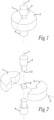
Fig. 1 is a schematic view of a first embodiment of a press tool; -
Fig. 2 is a schematic exploded view of the first embodiment of the press tool; -
Fig. 3 is an enlarged, schematic and perspective view of a punch device and associated elements according to the first embodiment as seen from an angle toward a rear end of the punch device; -
Fig. 4 is a view of the punch device and associated elements shown inFig. 3 as seen from an angle toward a front end top of the punch device; -
Fig. 5 is an exploded view of the punch device and associated elements shown inFig. 3 ; -
Fig. 6 is an axial front end view of the punch device and associated elements shown inFig. 3 ; -
Fig. 7 is a side view of the punch device and associated elements shown inFig. 3 ; -
Fig. 8 is a sectional view along the punch axis of the punch device and associated elements shown inFig. 3 ; -
Fig. 9 is a schematic sectional view of cutting insert green body in the press tool with misaligned front section and uneven burr; -
Fig. 10 is a schematic sectional view of a cutting insert green body in the press tool with adjusted front section and even burr; -
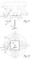
Fig. 11 is a view corresponding toFig. 3 showing the punch device and associated elements when the front section is in a start orientation; -
Fig. 12 is an axial view corresponding toFig. 11 , wherein the punch tool has been removed, and the start position of the front point is indicated; -
Fig. 13 is a view corresponding toFig. 3 showing the punch device and associated elements when the front section is in a target orientation; -
Fig. 14 is an axial view corresponding toFig. 13 , wherein the punch tool has been removed, and the start position and a first target position of the front point is indicated; -
Fig. 15 is a view corresponding toFig. 14 showing the start position and a second target position of the front point is indicated; -
Figs. 16 - 18 are side views along the punch axis corresponding toFig. 8 showing alternative embodiments of the press tool. - All the figures are schematic, not necessarily to scale, and generally only show parts which are necessary in order to elucidate the respective embodiments, whereas other parts may be omitted or merely suggested. Unless otherwise indicated, like reference numerals refer to like parts in different figures.
- In
Figs. 1 and 2 , the overall design of a first embodiment of the press tool according to the present invention is shown. The press tool is a split-die press tool and comprises twodie sections 1, 2. The press tool further comprises twopunch devices upper punch device 3 and a singlelower punch device 4. In the example embodiment, each of thedie sections 1, 2 and each of thepunch devices - Both die
sections 1, 2 are movably arranged along ahorizontal axis 5, wherein each is movable to a respective proximal position, and to several respective distal positions. Specifically, thedie sections 1, 2 are movable inward toward a centre, and outward away from the centre. - Both
punch devices punch axis 7, which in the example embodiment is vertical during normal operation of the press tool. Thepunch devices punches - During operation, the
die sections 1, 2 and thelower punch device 4 are moved to their respective proximal positions, whereby a closed cavity for compacting a powder therein is formed at the centre. - With reference to
Figs. 3 - 15 , features of the first embodiment are described, wherein, of the twopunch devices upper punch device 3 and therewith associated elements are shown and described. - The
punch device 3 comprises afront section 11 and arear section 14, whichrear section 14 is located directly axially rearward of thefront section 11. Thefront section 11 has a front end at the cavity, wherein the front end has an axial most forward point. The axially most forward point is a centralfront point 12, and specifically, located on a central longitudinal axis of the front section. Thefront point 12 is also the axially most forward point of thepunch device 3. In the first embodiment, thefront section 11 forms a front portion of an exchangeable punch tool, c.f.Fig. 5 . - The punch device comprises a
tool coupling part 15, which is located in the exchangeable punch tool at an axially rear end thereof. Thepunch device 3 comprises acomplementary coupling part 16, which complementary coupling part forms a coupling together with thetool coupling part 15. The coupling securely holds the exchangeable punch tool. The coupling constitutes a front portion of therear section 14. - The punch device comprises an abutment element in form of a
sleeve element 21. In the first embodiment, the sleeve element is an axially forwardopen box 21 with four elastically flexible sides. - An
arm member 17 extends axially along therear section 14 at a distance therefrom. The arm member is in form of a plate extending alongside the rear section along an associated side of thebox 21 wherein the plate faces therear section 14, specifically, a main surface of the plate faces the associated side of thebox 21. A gap is formed between thearm member 17 and the associated side of thebox 21. Thearm member 17 has an internally threaded through hole at an axially forward end, wherein anarm contact point 19 is located on a surface of the thread. - The first embodiment has a plurality of the
arm member 17, i.e. fourarm members 17. Thearm members 17 are arranged in pairs, wherein thearm members 17 of each pair are arranged at diametrically opposite sides of thepunch axis 7. As can be seen in the front end view ofFig. 6 , an axis x from afirst arm member 17 to asecond arm member 17 of a first pair is perpendicular to a corresponding axis y of a second pair. The axis x and y intersect thepunch axis 7. - Each
arm member 17 is connected to therear section 14 by ajoint unit 18 such that the distance from therear section 14 to thearm member 17, in a position axially forward of thejoint unit 18, is adjustable. - The
joint unit 18 according to the first embodiment comprises a circular plate, which forms a circular flange extending radially outward relative therear section 14. Thearm member 17 extends axially forward from a radial outer portion of the flange. Thejoint unit 18 is configured and arranged to allow each of thearm members 17 to flex by bending in response to an increase and/or decrease in the distance from therear section 14 to a respective one of thearm members 17. Thejoint unit 18 comprisesprimary regions 22 in form of portions therear section 14 andsecondary regions 23 in form of a portion of each of thearm members 17. Both the primary and thesecondary regions rear section 14 and each of thearm members 17 bend at thejoint unit 18 by the primary andsecondary regions - The secondary region has a smaller elastic deformation stiffness than the primary region.
- A
spacer element 10 is movably arranged in the press tool, wherein thespacer element 10 is operable to translate from an associated start position to an associated target position. Thespacer element 10 is arranged and configured to engage a respective one of the plurality of thearm member 17 via an associatedarm contact point 19, and therear section 14 via an associatedrear contact point 20. Therear contact point 20 is in form of an abutment surface on an associated side of thebox 21. The secondary region of thejoint unit 18 forming a forward portion of the arm member, is located directly axially rearward of thearm contact point 19. - In the first embodiment, the
spacer element 10 is in from of an externally threaded screw having a hexagonal head. Thespacer element 10 is arranged to engage thearm contact point 19 on the surface of the internal threads in the through hole of thearm member 17 with the surface of the external thread of the screw. Furthermore, thespacer element 10 is arranged to engage therear contact point 20 on the side surface of thebox 21 with an end surface of the screw. - The first embodiment of the press tool comprises four
such spacer elements 10. As can be seen in the front end view ofFig. 6 , rear contact points 20 are arranged in pairs on the axis x and the axis y, wherein the rear contact points 20 of each pair is arranged at diametrically opposite sides of thepunch axis 7. - The press tool is operable to form a cutting insert
green body 8 by compacting a powder, which in the present example embodiment is a cemented carbide powder. During operation, thedie sections 1, 2 and thelower punch device 4 are moved to a proximal position such that a cavity is formed in a central region. The powder is introduced into the cavity, which powder is compressed therein by moving theupper punch device 3 to the proximal position thereof. Thereafter, thedie sections 1, 2 and/or thepunch devices green body 8 is removed. -
Fig. 9 shows a schematic cross sectional view of the press tool after the powder has been compacted to a cutting insertgreen body 8. In the press tool, theupper punch device 3 is misaligned. Thefront point 12 is off centre and, as seen in the view of the figure, located slightly to the left of the centre of the cavity. This results in thatpress burr 9 is formed unevenly along the edges of the cutting insertgreen body 8. For clarity, the cutting insertgreen body 8 and thepress burr 9 is shown enlarged and exaggerated inFigs. 9 and 10 . -
Figs. 11 and 12 show thefront section 11 when it is in the start orientation corresponding to the orientation shown inFig. 9 . Thefront point 12 is in a start position. Thespacer element 10 is in the start position, wherein an end surface of the screw is in contact with therear contact point 20. A distance from thearm contact point 19 to therear contact point 20 is arear start distance 29. Thejoint unit 18 is in a start state in form of a relaxed state. - In order to achieve a more even burr, the
front section 11 is adjustable to assume a target orientation. In the example embodiment, the target orientation differs from the start orientation in that thefront point 12 is located afront target distance 25 from the position of thefront point 12 when the front section is in the start orientation. In the target position, the front end of thefront section 11 is centered in the die such that the burr of the insertgreen body 8 is more even. Thefront target distance 25 is measured as seen in an axial plane onto which both the start position and the target position of thefront point 12 have been projected. In the example embodiment, thefront target distance 25 is in a radial direction corresponding to the x axis. The axial plane corresponds to the view ofFigs. 12 ,14 and15 . - In other embodiments, the target orientation differs from the start orientation instead in that the
front section 11 is rotated and/or the front target distance is in any other direction in the axial plane. - In the first embodiment, the target orientation of the
front section 11 is achieved by changing the distance measured from the arm contact point to the rear contact point such that therear section 14 flexes by bending at thejoint unit 18. Therein, mainly thesecondary region 23 is bent and elastically deformed, c.f.Fig. 13 . However, also theprimary region 22 is slightly bent and elastically deformed such that thefront point 12 is moved thefront target distance 25. The joint unit18 is forced into a target state. - The change in distance between the
arm contact point 19 andrear contact point 20 is achieved by operating thespacer element 10, wherein the spacer element is in form of a screw. When the screw is rotated in the threaded hole of thearm member 17 to move radially inward toward thepunch axis 7, the end surface of the screw engages therear section 14 by abutting against thecontact point 20 on the side surface of thebox 21. At the same time, the threads of the screw engage thearm contact point 19 with the external threads interacting with the internal threads of thearm member 17. Thereby, the screw forces thearm contact point 19 and therear contact point 20 apart. When the screw has been turned sufficiently, the screw has translated aspacer target distance 26 through the through hole in thearm member 17, and the distance from thearm contact point 19 to therear contact point 20 is the rear target distance. Thereby, thefront point 12 of thefront section 11 has been moved thefront target distance 25. - Specifically, in the first embodiment, the screw is a fine-threaded M10 screw having a pitch 0.75 mm. When the screw is rotated one revolution, it translates a
spacer target distance 26 of 0.75mm. Thereby, therear start distance 29 increases by 0.75mm to therear target distance 24. In this embodiment, as a result, thefront point 12 will move approximately 10 µm reaching the front target distance of 10 µm. Thanks to the hexagonal head, the 360° revolution can be subdivided into six indices. Thereby, the rear start distance can be increased by steps of 0.75/6 mm (index 0 = 0 mm, index 1 = 0,125 mm,index 2 = 0.25 mm, to index 6 = 0.75 mm) to reach therear target distance 24 of 0.75 mm in 6 steps. Thereby, thefront target distance 25 can be increased by steps of 10/6 micrometer (index 0 = 0 micrometer, index 1 = 1.67 micrometer,index 2 = 3.33 micrometer, index 6 = 10 micrometer). In this embodiment the ratio of the spacer target distance and the front target distance is 75. - In
Fig. 15 , the position of thefront point 12 is adjusted asecond target distance 25. As can be seen, two of the four spacer elements in form of screws have been operated by turning. Afirst screw 10a is rotated such that it translates an associated spacer target distance through the through hole of thearm member 17. Asecond screw 10b is rotated such that it translates an associated spacer target distance through the through hole of thearm member 17. Thereby, the associated arm contact points 19a, 19b and associated rear contact points 20a, 20b are separated by associatedrear target distances 24a, b. The first and second associatedrear target distances 24a, b have different directions, i.e. they extend perpendicular to each other along x and y axis respectively. - In
Fig. 15 furthermore twomore spacer elements 10c can be seen. These are both shown in positions, wherein an end surface is separated from the associatedrear contact point 20. When thethird spacer 10c element is operated, a therewith associatedrear target distance 24 andfront target distance 25, is aligned and opposite to therear target distance 24 andfront target distance 25 associated with the first spacer element 10ab, respectively. - In
Figs. 16 - 18 , alternative embodiments of the press tool are shown, which mainly differ from the first embodiment by thespacer element 10. Therefore, in the following only thespacer element 10 and therewith relevant features are described. - In the second embodiment shown in
Fig. 16 , the spacer element in is in form of awedge 10. In the second embodiment, thespacer target distance 26 is along thepunch axis 7 and perpendicular to therear target distance 24 and front target distance. Thearm contact point 19 is arranged on a main surface of thearm member 17 which is facing thepunch axis 7. Therear contact point 20 is on the side surface of thebox 21 as in the first embodiment. An advantage with the second embodiment is that the ratio between the spacer target distance and the front target distance is large if the wedge angle is small. - The third embodiment of
Fig. 17 corresponds to the first embodiment except that aspring element 28 is arranged between the end surface of thescrew 10 and therear contact point 20 on the side surface of thebox 21. An advantage with the fourth embodiment is that the ratio between the spacer target distance and the front target distance is large. - In the fourth embodiment of
Fig. 18 , thespacer element 10 comprises a screw and alever element 27. The screw is arranged similar to the first embodiment, wherein thearm contact point 19 is on a surface of the thread in the through hole in thearm member 17. The rear contact point is on the side surface of thebox 21 and in contact with the base of thelever element 27. One end of thelever element 17 is pivotably connected to thearm member 17, and the other end abuts against the end surface of the screw. An advantage with the third embodiment is that the ratio between the spacer target distance and the front target distance is large.
Claims (15)
- A press tool for forming, by compacting a powder, a cutting insert green body (8), comprising- a cavity for receiving the powder to be compacted, and- a punch device (3), which is movably arranged along a punch axis (7) for compacting the powder in the cavity, wherein the punch axis (7) defines a axial directions and axial planes,wherein the punch device (3) comprises,- an axially extending front section with a front end at the cavity, which front section is operable to assume a start orientation and a target orientation, and- an axially extending rear section, which is connected with and located axially rearward of the front section,characterized in that
the press tool further comprises- a movably arranged spacer element (10), wherein the spacer element (10) is operable to translate from a start position to a target position,- an arm member (17), which extends axially along the rear section (14) at a distance therefrom, and- a joint unit (18),wherein- the joint unit (18), which connects the arm member (17) and the rear section such that the distance from the rear section (14) to the arm member (17), in a position axially in front of the joint unit (18), is adjustable,- the spacer element (10) is arranged and configured to engage the arm member (17) via an arm contact point (19) and the rear section via a rear contact point (20),- when the spacer element (10) is in the start position, as seen in an axial projection on an axial plane, the distance from the arm contact point (19) to the rear contact point (20) is a rear start distance (29), whereby the joint unit (18) is in a start state and the front section (11) is in the start orientation, and,- when the spacer element (10) is in the target position, as seen in an axial projection on an axial plane, the distance from the arm contact point (19) to the rear contact point (20) is a rear target distance (24), whereby the joint unit (18) is in a target state biased toward the start state and the front section (11) is in the target orientation. - The press tool as claimed in claim 1, wherein the joint unit (18) comprises a primary region (22) at the rear section (14), which primary region (22) is elastic.
- The press tool as claimed in claim 2, wherein the joint unit (18) comprises a secondary region (23) in form of a portion of the arm member (17), which secondary region (23) is elastic, wherein, in the target state of the joint unit (18), the secondary region (23) has a smaller bending stiffness than the primary region (22).
- The press tool as claimed in any preceding claim, wherein the front end of the front section (11) has an axial most forward point, wherein a front point (12) is a central point located in the same axial plane as the axial most forward point, wherein, as seen in an axial projection on an axial plane, the position of the front point (12) when the front section (11) is in the target orientation is located a front target distance (25) from the position of the front point (12) when the front section (11) is in the start orientation.
- The press tool as claimed in claim 4, wherein,- when the spacer element (10) is in the start position, the spacer element (10) is in engagement with the arm contact point (19) and the rear contact point (20), and the start state of the joint unit (18) is a relaxed state,- when the spacer element (10) is in target position, the spacer element (10) has translated a spacer target distance (26), and wherein a ratio between the spacer target distance (26) and the front target distance (25) is at least 20.
- The press tool as claimed in any preceding claim, wherein- the front section (11) is comprised in an exchangeable punch tool, which furthermore comprises a tool coupling part (15) at an axially rear end,- the punch device (3) comprises a complementary coupling part (16), which complementary coupling part (16) forms a coupling together with the tool coupling part (15), wherein the coupling is located in the rear section (14),- the punch device (3) comprises an abutment element, which extends axially along without contacting the coupling, and wherein- the rear contact point (20) is located on the abutment element (21).
- The press tool as claimed in claim 6, wherein the abutment element is a sleeve element (21) extending concentrically with the punch axis (7), which sleeve element (21) has flexible walls.
- The press tool as claimed in any preceding claim, further comprising a spring element, which is in engagement with the spacer element (10) in a first end and with the rear contact point (20) of the rear section (14) with a second end.
- The press tool as claimed in any preceding claim, wherein the spacer element (10) is arranged between the arm member (17) and the rear section (14).
- The press tool as claimed in claim 9, wherein the spacer element (10) is a screw.
- The press tool as claimed in claim 10, wherein the arm member (17) comprises a threaded through hole, the screw is in threaded engagement with the thread in the through hole, and the arm contact point (19) is located on the thread of the through hole.
- The press tool as claimed in any preceding claim, wherein the press tool comprises- a plurality of the spacer element (10), which each are operable to move from an associated start position to an associated target position,- a plurality of the arm member (17),wherein- each spacer element (10) is arranged and configured to engage a respective one of the plurality of the arm member (17) via an associated arm contact point (19) and the rear section via an associated rear contact point,- when all of the plurality of the spacer element (10) are in their associated start position, the joint unit (18) is in the start state and the front section is in the start orientation, and,- when any one of the plurality of the spacer element (10) is in the associated target position and all other of the plurality spacer element (10) are in their respective associated start position, as seen in an axial projection on an axial plane and with respect to the any one of the plurality of spacer elements (10), the distance from the associated arm member contact point (19) a to the associated rear contact point (20) is an associated rear target distance (24), whereby the joint unit (18) is in an associated target state biased toward the start state and the front section (11) is in an associated target orientation.
- The press tool as claimed in claim 12, wherein- all associated rear target distances (24) have a different direction.
- The press tool as claimed in claim 4 and 13, wherein- as seen in an axial projection on an axial plane, the position of the front point (12) when the front section is in the associated target orientation is located an associated front target distance (25) from the position of the front point when the front section is in the start orientation, and- a first associated rear target distance (24) and a first associated front target distance (25) are perpendicular to a second associated rear target distance (24) and second associated front target distance (25), respectively.
- The press tool as claimed in claim 14, wherein the first associated rear target distance (24) and the first associated front target distance (25) are aligned and opposite to a third associated rear target distance (24) and third associated front target distance (25), respectively.
Priority Applications (3)
| Application Number | Priority Date | Filing Date | Title |
|---|---|---|---|
| EP23219661.8A EP4574413B1 (en) | 2023-12-22 | 2023-12-22 | Press tool |
| CN202480073876.0A CN122295203A (en) | 2023-12-22 | 2024-10-15 | compression tools |
| PCT/EP2024/079021 WO2025131370A1 (en) | 2023-12-22 | 2024-10-15 | Press tool |
Applications Claiming Priority (1)
| Application Number | Priority Date | Filing Date | Title |
|---|---|---|---|
| EP23219661.8A EP4574413B1 (en) | 2023-12-22 | 2023-12-22 | Press tool |
Publications (2)
| Publication Number | Publication Date |
|---|---|
| EP4574413A1 true EP4574413A1 (en) | 2025-06-25 |
| EP4574413B1 EP4574413B1 (en) | 2026-07-22 |
Family
ID=89321417
Family Applications (1)
| Application Number | Title | Priority Date | Filing Date |
|---|---|---|---|
| EP23219661.8A Active EP4574413B1 (en) | 2023-12-22 | 2023-12-22 | Press tool |
Country Status (3)
| Country | Link |
|---|---|
| EP (1) | EP4574413B1 (en) |
| CN (1) | CN122295203A (en) |
| WO (1) | WO2025131370A1 (en) |
Citations (4)
| Publication number | Priority date | Publication date | Assignee | Title |
|---|---|---|---|---|
| US20190015900A1 (en) * | 2016-03-18 | 2019-01-17 | Horn Hartstoffe Gmbh | Manufacturing a hard-metal pressed article |
| CN109954878A (en) * | 2017-12-24 | 2019-07-02 | 株洲新奥燃气有限公司 | A kind of punch device |
| CN115379912A (en) * | 2020-04-08 | 2022-11-22 | 瓦尔特公开股份有限公司 | Pressing tool and method for forming a cutting insert green body having a through hole |
| EP4116011A1 (en) * | 2021-07-06 | 2023-01-11 | AB Sandvik Coromant | Split-die press tool |
-
2023
- 2023-12-22 EP EP23219661.8A patent/EP4574413B1/en active Active
-
2024
- 2024-10-15 WO PCT/EP2024/079021 patent/WO2025131370A1/en active Pending
- 2024-10-15 CN CN202480073876.0A patent/CN122295203A/en active Pending
Patent Citations (4)
| Publication number | Priority date | Publication date | Assignee | Title |
|---|---|---|---|---|
| US20190015900A1 (en) * | 2016-03-18 | 2019-01-17 | Horn Hartstoffe Gmbh | Manufacturing a hard-metal pressed article |
| CN109954878A (en) * | 2017-12-24 | 2019-07-02 | 株洲新奥燃气有限公司 | A kind of punch device |
| CN115379912A (en) * | 2020-04-08 | 2022-11-22 | 瓦尔特公开股份有限公司 | Pressing tool and method for forming a cutting insert green body having a through hole |
| EP4116011A1 (en) * | 2021-07-06 | 2023-01-11 | AB Sandvik Coromant | Split-die press tool |
Also Published As
| Publication number | Publication date |
|---|---|
| WO2025131370A1 (en) | 2025-06-26 |
| CN122295203A (en) | 2026-06-26 |
| EP4574413B1 (en) | 2026-07-22 |
Similar Documents
| Publication | Publication Date | Title |
|---|---|---|
| EP1123766B1 (en) | Tool assembly | |
| CN101622086B (en) | Reorientable rotatable processing tool for cutting and/or shaping plate element | |
| US5320636A (en) | Endoscopic scissors instrument with cammed surface end effectors | |
| JP2628824B2 (en) | Fixed steady rest with built-in centerline adjustment mechanism | |
| JP2024536329A (en) | Coating machine die head flow rate adjustment mechanism and its operating method | |
| JP2010509083A (en) | Final adjustment system using haptic feedback | |
| KR101526610B1 (en) | Metal Cutting Tools | |
| EP2905101B1 (en) | Peeling tool | |
| KR20050086407A (en) | Rotatable cutting tool | |
| US7114890B2 (en) | Cutting tool adjustment device | |
| WO2025131370A1 (en) | Press tool | |
| EP1225997B1 (en) | Adjustment of cutting inserts in a cutting tool | |
| US11285535B2 (en) | Press-tool | |
| JP2020203316A (en) | Tool holder | |
| US6244151B1 (en) | Apparatus for adjusting cutting bar | |
| WO1995024287A1 (en) | Cutting tool | |
| JP5971577B2 (en) | Blade adjustment mechanism | |
| JP2804696B2 (en) | Cutting tools | |
| KR20230139868A (en) | Deburring tool | |
| JP2779112B2 (en) | Cutting tools | |
| US12179271B2 (en) | Press tool and method for forming a cutting insert green body having a through hole | |
| EP4640345A1 (en) | Boring head | |
| JP2748847B2 (en) | Cutting tools | |
| JP2748846B2 (en) | Cutting tools | |
| JP3595578B2 (en) | Punch assembly and method of manufacturing the same |
Legal Events
| Date | Code | Title | Description |
|---|---|---|---|
| PUAI | Public reference made under article 153(3) epc to a published international application that has entered the european phase |
Free format text: ORIGINAL CODE: 0009012 |
|
| STAA | Information on the status of an ep patent application or granted ep patent |
Free format text: STATUS: THE APPLICATION HAS BEEN PUBLISHED |
|
| AK | Designated contracting states |
Kind code of ref document: A1 Designated state(s): AL AT BE BG CH CY CZ DE DK EE ES FI FR GB GR HR HU IE IS IT LI LT LU LV MC ME MK MT NL NO PL PT RO RS SE SI SK SM TR |
|
| STAA | Information on the status of an ep patent application or granted ep patent |
Free format text: STATUS: REQUEST FOR EXAMINATION WAS MADE |
|
| 17P | Request for examination filed |
Effective date: 20260102 |
|
| REG | Reference to a national code |
Ref country code: DE Ref legal event code: R079 Free format text: PREVIOUS MAIN CLASS: B30B0011020000 Ipc: B22F0003030000 Ref document number: 602023020188 Country of ref document: DE |
|
| GRAP | Despatch of communication of intention to grant a patent |
Free format text: ORIGINAL CODE: EPIDOSNIGR1 |
|
| STAA | Information on the status of an ep patent application or granted ep patent |
Free format text: STATUS: GRANT OF PATENT IS INTENDED |
|
| RIC1 | Information provided on ipc code assigned before grant |
Ipc: B22F 3/03 20060101AFI20260223BHEP Ipc: B28B 3/02 20060101ALI20260223BHEP Ipc: B28B 3/08 20060101ALI20260223BHEP Ipc: B30B 15/06 20060101ALI20260223BHEP Ipc: B30B 11/00 20060101ALI20260223BHEP Ipc: B30B 11/02 20060101ALI20260223BHEP Ipc: B30B 15/02 20060101ALI20260223BHEP |
|
| INTG | Intention to grant announced |
Effective date: 20260324 |
|
| GRAS | Grant fee paid |
Free format text: ORIGINAL CODE: EPIDOSNIGR3 |
|
| GRAA | (expected) grant |
Free format text: ORIGINAL CODE: 0009210 |
|
| STAA | Information on the status of an ep patent application or granted ep patent |
Free format text: STATUS: THE PATENT HAS BEEN GRANTED |
|
| P01 | Opt-out of the competence of the unified patent court (upc) registered |
Free format text: CASE NUMBER: UPC_APP_0015999_4574413/2026 Effective date: 20260520 |
|
| AK | Designated contracting states |
Kind code of ref document: B1 Designated state(s): AL AT BE BG CH CY CZ DE DK EE ES FI FR GB GR HR HU IE IS IT LI LT LU LV MC ME MK MT NL NO PL PT RO RS SE SI SK SM TR |
|
| REG | Reference to a national code |
Ref country code: CH Ref legal event code: F10 Free format text: ST27 STATUS EVENT CODE: U-0-0-F10-F00 (AS PROVIDED BY THE NATIONAL OFFICE) Effective date: 20260722 Ref country code: GB Ref legal event code: FG4D |
|
| REG | Reference to a national code |
Ref country code: IE Ref legal event code: FG4D |
|
| REG | Reference to a national code |
Ref country code: DE Ref legal event code: R096 Ref document number: 602023020188 Country of ref document: DE |