EP4574401A1 - Transmission welding apparatus and welding method - Google Patents
Transmission welding apparatus and welding method Download PDFInfo
- Publication number
- EP4574401A1 EP4574401A1 EP23217984.6A EP23217984A EP4574401A1 EP 4574401 A1 EP4574401 A1 EP 4574401A1 EP 23217984 A EP23217984 A EP 23217984A EP 4574401 A1 EP4574401 A1 EP 4574401A1
- Authority
- EP
- European Patent Office
- Prior art keywords
- pressure
- welding apparatus
- transmission
- plate
- transmission welding
- Prior art date
- Legal status (The legal status is an assumption and is not a legal conclusion. Google has not performed a legal analysis and makes no representation as to the accuracy of the status listed.)
- Pending
Links
Images




Classifications
-
- B—PERFORMING OPERATIONS; TRANSPORTING
- B29—WORKING OF PLASTICS; WORKING OF SUBSTANCES IN A PLASTIC STATE IN GENERAL
- B29C—SHAPING OR JOINING OF PLASTICS; SHAPING OF MATERIAL IN A PLASTIC STATE, NOT OTHERWISE PROVIDED FOR; AFTER-TREATMENT OF THE SHAPED PRODUCTS, e.g. REPAIRING
- B29C65/00—Joining or sealing of preformed parts, e.g. welding of plastics materials; Apparatus therefor
- B29C65/02—Joining or sealing of preformed parts, e.g. welding of plastics materials; Apparatus therefor by heating, with or without pressure
- B29C65/18—Joining or sealing of preformed parts, e.g. welding of plastics materials; Apparatus therefor by heating, with or without pressure using heated tools
- B29C65/20—Joining or sealing of preformed parts, e.g. welding of plastics materials; Apparatus therefor by heating, with or without pressure using heated tools with direct contact, e.g. using "mirror"
-
- B—PERFORMING OPERATIONS; TRANSPORTING
- B29—WORKING OF PLASTICS; WORKING OF SUBSTANCES IN A PLASTIC STATE IN GENERAL
- B29C—SHAPING OR JOINING OF PLASTICS; SHAPING OF MATERIAL IN A PLASTIC STATE, NOT OTHERWISE PROVIDED FOR; AFTER-TREATMENT OF THE SHAPED PRODUCTS, e.g. REPAIRING
- B29C65/00—Joining or sealing of preformed parts, e.g. welding of plastics materials; Apparatus therefor
- B29C65/02—Joining or sealing of preformed parts, e.g. welding of plastics materials; Apparatus therefor by heating, with or without pressure
- B29C65/14—Joining or sealing of preformed parts, e.g. welding of plastics materials; Apparatus therefor by heating, with or without pressure using wave energy, i.e. electromagnetic radiation, or particle radiation
-
- B—PERFORMING OPERATIONS; TRANSPORTING
- B29—WORKING OF PLASTICS; WORKING OF SUBSTANCES IN A PLASTIC STATE IN GENERAL
- B29C—SHAPING OR JOINING OF PLASTICS; SHAPING OF MATERIAL IN A PLASTIC STATE, NOT OTHERWISE PROVIDED FOR; AFTER-TREATMENT OF THE SHAPED PRODUCTS, e.g. REPAIRING
- B29C65/00—Joining or sealing of preformed parts, e.g. welding of plastics materials; Apparatus therefor
- B29C65/02—Joining or sealing of preformed parts, e.g. welding of plastics materials; Apparatus therefor by heating, with or without pressure
- B29C65/14—Joining or sealing of preformed parts, e.g. welding of plastics materials; Apparatus therefor by heating, with or without pressure using wave energy, i.e. electromagnetic radiation, or particle radiation
- B29C65/1403—Joining or sealing of preformed parts, e.g. welding of plastics materials; Apparatus therefor by heating, with or without pressure using wave energy, i.e. electromagnetic radiation, or particle radiation characterised by the type of electromagnetic or particle radiation
- B29C65/1409—Visible light radiation
-
- B—PERFORMING OPERATIONS; TRANSPORTING
- B29—WORKING OF PLASTICS; WORKING OF SUBSTANCES IN A PLASTIC STATE IN GENERAL
- B29C—SHAPING OR JOINING OF PLASTICS; SHAPING OF MATERIAL IN A PLASTIC STATE, NOT OTHERWISE PROVIDED FOR; AFTER-TREATMENT OF THE SHAPED PRODUCTS, e.g. REPAIRING
- B29C65/00—Joining or sealing of preformed parts, e.g. welding of plastics materials; Apparatus therefor
- B29C65/02—Joining or sealing of preformed parts, e.g. welding of plastics materials; Apparatus therefor by heating, with or without pressure
- B29C65/14—Joining or sealing of preformed parts, e.g. welding of plastics materials; Apparatus therefor by heating, with or without pressure using wave energy, i.e. electromagnetic radiation, or particle radiation
- B29C65/1403—Joining or sealing of preformed parts, e.g. welding of plastics materials; Apparatus therefor by heating, with or without pressure using wave energy, i.e. electromagnetic radiation, or particle radiation characterised by the type of electromagnetic or particle radiation
- B29C65/1412—Infrared [IR] radiation
-
- B—PERFORMING OPERATIONS; TRANSPORTING
- B29—WORKING OF PLASTICS; WORKING OF SUBSTANCES IN A PLASTIC STATE IN GENERAL
- B29C—SHAPING OR JOINING OF PLASTICS; SHAPING OF MATERIAL IN A PLASTIC STATE, NOT OTHERWISE PROVIDED FOR; AFTER-TREATMENT OF THE SHAPED PRODUCTS, e.g. REPAIRING
- B29C66/00—General aspects of processes or apparatus for joining preformed parts
- B29C66/01—General aspects dealing with the joint area or with the area to be joined
- B29C66/05—Particular design of joint configurations
- B29C66/10—Particular design of joint configurations particular design of the joint cross-sections
- B29C66/11—Joint cross-sections comprising a single joint-segment, i.e. one of the parts to be joined comprising a single joint-segment in the joint cross-section
- B29C66/112—Single lapped joints
-
- B—PERFORMING OPERATIONS; TRANSPORTING
- B29—WORKING OF PLASTICS; WORKING OF SUBSTANCES IN A PLASTIC STATE IN GENERAL
- B29C—SHAPING OR JOINING OF PLASTICS; SHAPING OF MATERIAL IN A PLASTIC STATE, NOT OTHERWISE PROVIDED FOR; AFTER-TREATMENT OF THE SHAPED PRODUCTS, e.g. REPAIRING
- B29C66/00—General aspects of processes or apparatus for joining preformed parts
- B29C66/01—General aspects dealing with the joint area or with the area to be joined
- B29C66/05—Particular design of joint configurations
- B29C66/10—Particular design of joint configurations particular design of the joint cross-sections
- B29C66/13—Single flanged joints; Fin-type joints; Single hem joints; Edge joints; Interpenetrating fingered joints; Other specific particular designs of joint cross-sections not provided for in groups B29C66/11 - B29C66/12
- B29C66/131—Single flanged joints, i.e. one of the parts to be joined being rigid and flanged in the joint area
-
- B—PERFORMING OPERATIONS; TRANSPORTING
- B29—WORKING OF PLASTICS; WORKING OF SUBSTANCES IN A PLASTIC STATE IN GENERAL
- B29C—SHAPING OR JOINING OF PLASTICS; SHAPING OF MATERIAL IN A PLASTIC STATE, NOT OTHERWISE PROVIDED FOR; AFTER-TREATMENT OF THE SHAPED PRODUCTS, e.g. REPAIRING
- B29C66/00—General aspects of processes or apparatus for joining preformed parts
- B29C66/01—General aspects dealing with the joint area or with the area to be joined
- B29C66/05—Particular design of joint configurations
- B29C66/301—Three-dimensional joints, i.e. the joined area being substantially non-flat
-
- B—PERFORMING OPERATIONS; TRANSPORTING
- B29—WORKING OF PLASTICS; WORKING OF SUBSTANCES IN A PLASTIC STATE IN GENERAL
- B29C—SHAPING OR JOINING OF PLASTICS; SHAPING OF MATERIAL IN A PLASTIC STATE, NOT OTHERWISE PROVIDED FOR; AFTER-TREATMENT OF THE SHAPED PRODUCTS, e.g. REPAIRING
- B29C66/00—General aspects of processes or apparatus for joining preformed parts
- B29C66/50—General aspects of joining tubular articles; General aspects of joining long products, i.e. bars or profiled elements; General aspects of joining single elements to tubular articles, hollow articles or bars; General aspects of joining several hollow-preforms to form hollow or tubular articles
- B29C66/51—Joining tubular articles, profiled elements or bars; Joining single elements to tubular articles, hollow articles or bars; Joining several hollow-preforms to form hollow or tubular articles
- B29C66/52—Joining tubular articles, bars or profiled elements
- B29C66/524—Joining profiled elements
-
- B—PERFORMING OPERATIONS; TRANSPORTING
- B29—WORKING OF PLASTICS; WORKING OF SUBSTANCES IN A PLASTIC STATE IN GENERAL
- B29C—SHAPING OR JOINING OF PLASTICS; SHAPING OF MATERIAL IN A PLASTIC STATE, NOT OTHERWISE PROVIDED FOR; AFTER-TREATMENT OF THE SHAPED PRODUCTS, e.g. REPAIRING
- B29C66/00—General aspects of processes or apparatus for joining preformed parts
- B29C66/80—General aspects of machine operations or constructions and parts thereof
- B29C66/81—General aspects of the pressing elements, i.e. the elements applying pressure on the parts to be joined in the area to be joined, e.g. the welding jaws or clamps
- B29C66/812—General aspects of the pressing elements, i.e. the elements applying pressure on the parts to be joined in the area to be joined, e.g. the welding jaws or clamps characterised by the composition, by the structure, by the intensive physical properties or by the optical properties of the material constituting the pressing elements, e.g. constituting the welding jaws or clamps
- B29C66/8126—General aspects of the pressing elements, i.e. the elements applying pressure on the parts to be joined in the area to be joined, e.g. the welding jaws or clamps characterised by the composition, by the structure, by the intensive physical properties or by the optical properties of the material constituting the pressing elements, e.g. constituting the welding jaws or clamps characterised by the intensive physical properties or by the optical properties of the material constituting the pressing elements, e.g. constituting the welding jaws or clamps
- B29C66/81266—Optical properties, e.g. transparency, reflectivity
- B29C66/81267—Transparent to electromagnetic radiation, e.g. to visible light
-
- B—PERFORMING OPERATIONS; TRANSPORTING
- B29—WORKING OF PLASTICS; WORKING OF SUBSTANCES IN A PLASTIC STATE IN GENERAL
- B29C—SHAPING OR JOINING OF PLASTICS; SHAPING OF MATERIAL IN A PLASTIC STATE, NOT OTHERWISE PROVIDED FOR; AFTER-TREATMENT OF THE SHAPED PRODUCTS, e.g. REPAIRING
- B29C66/00—General aspects of processes or apparatus for joining preformed parts
- B29C66/80—General aspects of machine operations or constructions and parts thereof
- B29C66/81—General aspects of the pressing elements, i.e. the elements applying pressure on the parts to be joined in the area to be joined, e.g. the welding jaws or clamps
- B29C66/814—General aspects of the pressing elements, i.e. the elements applying pressure on the parts to be joined in the area to be joined, e.g. the welding jaws or clamps characterised by the design of the pressing elements, e.g. of the welding jaws or clamps
- B29C66/8145—General aspects of the pressing elements, i.e. the elements applying pressure on the parts to be joined in the area to be joined, e.g. the welding jaws or clamps characterised by the design of the pressing elements, e.g. of the welding jaws or clamps characterised by the constructional aspects of the pressing elements, e.g. of the welding jaws or clamps
-
- B—PERFORMING OPERATIONS; TRANSPORTING
- B29—WORKING OF PLASTICS; WORKING OF SUBSTANCES IN A PLASTIC STATE IN GENERAL
- B29C—SHAPING OR JOINING OF PLASTICS; SHAPING OF MATERIAL IN A PLASTIC STATE, NOT OTHERWISE PROVIDED FOR; AFTER-TREATMENT OF THE SHAPED PRODUCTS, e.g. REPAIRING
- B29C66/00—General aspects of processes or apparatus for joining preformed parts
- B29C66/80—General aspects of machine operations or constructions and parts thereof
- B29C66/81—General aspects of the pressing elements, i.e. the elements applying pressure on the parts to be joined in the area to be joined, e.g. the welding jaws or clamps
- B29C66/814—General aspects of the pressing elements, i.e. the elements applying pressure on the parts to be joined in the area to be joined, e.g. the welding jaws or clamps characterised by the design of the pressing elements, e.g. of the welding jaws or clamps
- B29C66/8145—General aspects of the pressing elements, i.e. the elements applying pressure on the parts to be joined in the area to be joined, e.g. the welding jaws or clamps characterised by the design of the pressing elements, e.g. of the welding jaws or clamps characterised by the constructional aspects of the pressing elements, e.g. of the welding jaws or clamps
- B29C66/81451—General aspects of the pressing elements, i.e. the elements applying pressure on the parts to be joined in the area to be joined, e.g. the welding jaws or clamps characterised by the design of the pressing elements, e.g. of the welding jaws or clamps characterised by the constructional aspects of the pressing elements, e.g. of the welding jaws or clamps being adaptable to the surface of the joint
-
- B—PERFORMING OPERATIONS; TRANSPORTING
- B29—WORKING OF PLASTICS; WORKING OF SUBSTANCES IN A PLASTIC STATE IN GENERAL
- B29C—SHAPING OR JOINING OF PLASTICS; SHAPING OF MATERIAL IN A PLASTIC STATE, NOT OTHERWISE PROVIDED FOR; AFTER-TREATMENT OF THE SHAPED PRODUCTS, e.g. REPAIRING
- B29C66/00—General aspects of processes or apparatus for joining preformed parts
- B29C66/80—General aspects of machine operations or constructions and parts thereof
- B29C66/81—General aspects of the pressing elements, i.e. the elements applying pressure on the parts to be joined in the area to be joined, e.g. the welding jaws or clamps
- B29C66/814—General aspects of the pressing elements, i.e. the elements applying pressure on the parts to be joined in the area to be joined, e.g. the welding jaws or clamps characterised by the design of the pressing elements, e.g. of the welding jaws or clamps
- B29C66/8145—General aspects of the pressing elements, i.e. the elements applying pressure on the parts to be joined in the area to be joined, e.g. the welding jaws or clamps characterised by the design of the pressing elements, e.g. of the welding jaws or clamps characterised by the constructional aspects of the pressing elements, e.g. of the welding jaws or clamps
- B29C66/81461—General aspects of the pressing elements, i.e. the elements applying pressure on the parts to be joined in the area to be joined, e.g. the welding jaws or clamps characterised by the design of the pressing elements, e.g. of the welding jaws or clamps characterised by the constructional aspects of the pressing elements, e.g. of the welding jaws or clamps being multi-lamellar or segmented, i.e. comprising a plurality of strips, plates or stacked elements
-
- B—PERFORMING OPERATIONS; TRANSPORTING
- B29—WORKING OF PLASTICS; WORKING OF SUBSTANCES IN A PLASTIC STATE IN GENERAL
- B29C—SHAPING OR JOINING OF PLASTICS; SHAPING OF MATERIAL IN A PLASTIC STATE, NOT OTHERWISE PROVIDED FOR; AFTER-TREATMENT OF THE SHAPED PRODUCTS, e.g. REPAIRING
- B29C66/00—General aspects of processes or apparatus for joining preformed parts
- B29C66/80—General aspects of machine operations or constructions and parts thereof
- B29C66/82—Pressure application arrangements, e.g. transmission or actuating mechanisms for joining tools or clamps
- B29C66/824—Actuating mechanisms
- B29C66/8242—Pneumatic or hydraulic drives
- B29C66/82421—Pneumatic or hydraulic drives using an inflatable element positioned between the joining tool and a backing-up part
-
- B—PERFORMING OPERATIONS; TRANSPORTING
- B29—WORKING OF PLASTICS; WORKING OF SUBSTANCES IN A PLASTIC STATE IN GENERAL
- B29C—SHAPING OR JOINING OF PLASTICS; SHAPING OF MATERIAL IN A PLASTIC STATE, NOT OTHERWISE PROVIDED FOR; AFTER-TREATMENT OF THE SHAPED PRODUCTS, e.g. REPAIRING
- B29C66/00—General aspects of processes or apparatus for joining preformed parts
- B29C66/80—General aspects of machine operations or constructions and parts thereof
- B29C66/83—General aspects of machine operations or constructions and parts thereof characterised by the movement of the joining or pressing tools
- B29C66/832—Reciprocating joining or pressing tools
- B29C66/8322—Joining or pressing tools reciprocating along one axis
-
- B—PERFORMING OPERATIONS; TRANSPORTING
- B29—WORKING OF PLASTICS; WORKING OF SUBSTANCES IN A PLASTIC STATE IN GENERAL
- B29C—SHAPING OR JOINING OF PLASTICS; SHAPING OF MATERIAL IN A PLASTIC STATE, NOT OTHERWISE PROVIDED FOR; AFTER-TREATMENT OF THE SHAPED PRODUCTS, e.g. REPAIRING
- B29C65/00—Joining or sealing of preformed parts, e.g. welding of plastics materials; Apparatus therefor
- B29C65/02—Joining or sealing of preformed parts, e.g. welding of plastics materials; Apparatus therefor by heating, with or without pressure
- B29C65/14—Joining or sealing of preformed parts, e.g. welding of plastics materials; Apparatus therefor by heating, with or without pressure using wave energy, i.e. electromagnetic radiation, or particle radiation
- B29C65/16—Laser beams
-
- B—PERFORMING OPERATIONS; TRANSPORTING
- B29—WORKING OF PLASTICS; WORKING OF SUBSTANCES IN A PLASTIC STATE IN GENERAL
- B29C—SHAPING OR JOINING OF PLASTICS; SHAPING OF MATERIAL IN A PLASTIC STATE, NOT OTHERWISE PROVIDED FOR; AFTER-TREATMENT OF THE SHAPED PRODUCTS, e.g. REPAIRING
- B29C66/00—General aspects of processes or apparatus for joining preformed parts
- B29C66/70—General aspects of processes or apparatus for joining preformed parts characterised by the composition, physical properties or the structure of the material of the parts to be joined; Joining with non-plastics material
- B29C66/72—General aspects of processes or apparatus for joining preformed parts characterised by the composition, physical properties or the structure of the material of the parts to be joined; Joining with non-plastics material characterised by the structure of the material of the parts to be joined
- B29C66/721—Fibre-reinforced materials
-
- B—PERFORMING OPERATIONS; TRANSPORTING
- B29—WORKING OF PLASTICS; WORKING OF SUBSTANCES IN A PLASTIC STATE IN GENERAL
- B29C—SHAPING OR JOINING OF PLASTICS; SHAPING OF MATERIAL IN A PLASTIC STATE, NOT OTHERWISE PROVIDED FOR; AFTER-TREATMENT OF THE SHAPED PRODUCTS, e.g. REPAIRING
- B29C66/00—General aspects of processes or apparatus for joining preformed parts
- B29C66/70—General aspects of processes or apparatus for joining preformed parts characterised by the composition, physical properties or the structure of the material of the parts to be joined; Joining with non-plastics material
- B29C66/73—General aspects of processes or apparatus for joining preformed parts characterised by the composition, physical properties or the structure of the material of the parts to be joined; Joining with non-plastics material characterised by the intensive physical properties of the material of the parts to be joined, by the optical properties of the material of the parts to be joined, by the extensive physical properties of the parts to be joined, by the state of the material of the parts to be joined or by the material of the parts to be joined being a thermoplastic or a thermoset
- B29C66/739—General aspects of processes or apparatus for joining preformed parts characterised by the composition, physical properties or the structure of the material of the parts to be joined; Joining with non-plastics material characterised by the intensive physical properties of the material of the parts to be joined, by the optical properties of the material of the parts to be joined, by the extensive physical properties of the parts to be joined, by the state of the material of the parts to be joined or by the material of the parts to be joined being a thermoplastic or a thermoset characterised by the material of the parts to be joined being a thermoplastic or a thermoset
- B29C66/7392—General aspects of processes or apparatus for joining preformed parts characterised by the composition, physical properties or the structure of the material of the parts to be joined; Joining with non-plastics material characterised by the intensive physical properties of the material of the parts to be joined, by the optical properties of the material of the parts to be joined, by the extensive physical properties of the parts to be joined, by the state of the material of the parts to be joined or by the material of the parts to be joined being a thermoplastic or a thermoset characterised by the material of the parts to be joined being a thermoplastic or a thermoset characterised by the material of at least one of the parts being a thermoplastic
- B29C66/73921—General aspects of processes or apparatus for joining preformed parts characterised by the composition, physical properties or the structure of the material of the parts to be joined; Joining with non-plastics material characterised by the intensive physical properties of the material of the parts to be joined, by the optical properties of the material of the parts to be joined, by the extensive physical properties of the parts to be joined, by the state of the material of the parts to be joined or by the material of the parts to be joined being a thermoplastic or a thermoset characterised by the material of the parts to be joined being a thermoplastic or a thermoset characterised by the material of at least one of the parts being a thermoplastic characterised by the materials of both parts being thermoplastics
-
- B—PERFORMING OPERATIONS; TRANSPORTING
- B29—WORKING OF PLASTICS; WORKING OF SUBSTANCES IN A PLASTIC STATE IN GENERAL
- B29C—SHAPING OR JOINING OF PLASTICS; SHAPING OF MATERIAL IN A PLASTIC STATE, NOT OTHERWISE PROVIDED FOR; AFTER-TREATMENT OF THE SHAPED PRODUCTS, e.g. REPAIRING
- B29C66/00—General aspects of processes or apparatus for joining preformed parts
- B29C66/80—General aspects of machine operations or constructions and parts thereof
- B29C66/81—General aspects of the pressing elements, i.e. the elements applying pressure on the parts to be joined in the area to be joined, e.g. the welding jaws or clamps
- B29C66/814—General aspects of the pressing elements, i.e. the elements applying pressure on the parts to be joined in the area to be joined, e.g. the welding jaws or clamps characterised by the design of the pressing elements, e.g. of the welding jaws or clamps
- B29C66/8145—General aspects of the pressing elements, i.e. the elements applying pressure on the parts to be joined in the area to be joined, e.g. the welding jaws or clamps characterised by the design of the pressing elements, e.g. of the welding jaws or clamps characterised by the constructional aspects of the pressing elements, e.g. of the welding jaws or clamps
- B29C66/81463—General aspects of the pressing elements, i.e. the elements applying pressure on the parts to be joined in the area to be joined, e.g. the welding jaws or clamps characterised by the design of the pressing elements, e.g. of the welding jaws or clamps characterised by the constructional aspects of the pressing elements, e.g. of the welding jaws or clamps comprising a plurality of single pressing elements, e.g. a plurality of sonotrodes, or comprising a plurality of single counter-pressing elements, e.g. a plurality of anvils, said plurality of said single elements being suitable for making a single joint
- B29C66/81465—General aspects of the pressing elements, i.e. the elements applying pressure on the parts to be joined in the area to be joined, e.g. the welding jaws or clamps characterised by the design of the pressing elements, e.g. of the welding jaws or clamps characterised by the constructional aspects of the pressing elements, e.g. of the welding jaws or clamps comprising a plurality of single pressing elements, e.g. a plurality of sonotrodes, or comprising a plurality of single counter-pressing elements, e.g. a plurality of anvils, said plurality of said single elements being suitable for making a single joint one placed behind the other in a single row in the feed direction
-
- B—PERFORMING OPERATIONS; TRANSPORTING
- B29—WORKING OF PLASTICS; WORKING OF SUBSTANCES IN A PLASTIC STATE IN GENERAL
- B29L—INDEXING SCHEME ASSOCIATED WITH SUBCLASS B29C, RELATING TO PARTICULAR ARTICLES
- B29L2031/00—Other particular articles
- B29L2031/30—Vehicles, e.g. ships or aircraft, or body parts thereof
- B29L2031/3076—Aircrafts
Definitions
- the present invention concerns a transmission welding apparatus for welding thermoplastic resin material parts and a method for transmission welding thermoplastic resin material parts.
- Transmission welding is a joining process by means of heat and pressure. Plastic material parts are joint by melting the interface between them and pressing them together. The heat is generated by laser radiation or infrared radiation. The pressure is applied via a transparent pressure plate driven by a pneumatic or hydraulic pressure generator. This process is well known for small parts. An exemplary welding method using infrared is described in the EP-patent application of the applicant EP 3 953 153 A1 .
- a transmission welding apparatus for welding thermoplastic resin material parts comprises at least one heat source emitting thermal radiation and at least one pressure device adapted to apply a welding pressure on the material parts.
- the pressure device comprises at least one pressure generator for supplying a pressure force, at least one pressure plate which is permeable to the thermal radiation and which is adapted to introduce the pressure force into the material parts, and at least on pressure transmission system for transferring the pressure force to the pressure plate.
- At least one pressure plate is segmented into a plurality of plate segments which are arranged movable relative to one another.
- thermoplastic resin material parts uses an inventive welding apparatus.
- the segmentation of a large pressure plate in a plurality of small plate segments enables a transmission welding of large material parts.
- the pressure segments can follow individually a local contour of the material parts.
- the plate segments are located on the material parts to be joined and follow their upper surface during the entire welding cycle inclusive compensation of thermal extension as well as deformations during the welding process.
- Splitting of a single pressure plates allows to perform the welding of the material parts with thickness variation in one short without changing or adaptation of the welding apparatus. This is very beneficial for welding with compensation of tolerances between the joined parts. Even curved material parts can be joint.
- Exemplary applications in the aircraft industry are the welding of stringers or doublers with ramps or thicknesses variation, of the stringers for fuselage, of for wing and empennage, of longitudinal joints, of circumferential joints, of components to bigger parts, e.g. for pressure bulk head, of movables or of frames.
- Exemplary heating sources are infrared lamps and halogen lamps emitting 1/3 of visible light and 2/3 of infrared light.
- every plate segment is pressure activated directly.
- the plate segments can be linked to another, this enabling a pressure activation of every second plate segment directly, whereas a plate segment between two active plate segments is moved passively via its rotational connection with the adjacent active plate segments.
- plate segments are in operation connection with the same pressure generator. By means of this, only a single pressure generator is necessary.
- plate segments are in operation connection with an individual pressure generator.
- the plate segment can be positioned in a very flexible manner to each other as they all have their own pressure generator.
- An exemplary pressure transmission comprises rods and at least one gliding element of a pressure generator housing.
- the rods extend between the at least one gliding element and the plate segments.
- the rods are positioned on opposite edge portions of a plate segment thus avoiding a tilting of the plate segment when the pressure is applied.
- guiding means for guiding the rods are provided.
- the at least one heat source can be positioned between the rods. By means of this, the heat source is positioned close to the plate segments.
- the heat source has such a length that it extends over all plate segments.
- two parallel heat sources are provided.
- sliding elements can be provided which carry the heat source and slide over the upper material part during welding.
- At least one thermal protection element is provided.
- a welding joint is made sequentially by moving the welding apparatus forward after a joint section is made. This enables the creating of joints which are longer than the transmission welding apparatus, in particular the extension of its plate segments in the direction of the joint.
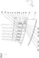
- FIG. 1 to 4 a first embodiment of an inventive transmission welding apparatus 1 is shown.
- the apparatus 1 is used to create a joint 2 at an interface between two material parts 4, 6 via heat and pressure.
- Exemplary material parts 4, 6 are thermoplastic resin material parts, in particular fibre reinforced thermoplastic parts.
- the apparatus 1 has a main extension in its moving direction, which is the longitudinal direction x of the joint 2.
- the apparatus 1 comprises one heat source 8 emitting thermal radiation, in particular infrared light, and one pressure device 10 adapted to apply a welding pressure on the material parts 4, 6.
- An exemplary heat source 8 is an infrared lamp or a halogen lamp.
- the pressure device 10 comprises a pressure generator 12 for supplying a pressure force, a segmented pressure plate 14 which is adapted to introduce the pressure force into the material parts 4, 6, and one pressure transmission system 16 for transferring the pressure force to the segmented pressure plate 14.
- the segmented pressure plate 14 is split into a plurality of plate segments 18.
- the plate segments 14a, 14b are arranged adjacent to another in longitudinal direction x and are in operation connection with the pressure generator 12 via the pressure transmission system 16. They are movable relative to one another in vertical direction z. They are made of a material that is permeable to thermal radiation such as transparent glass. They have a greater extension in a direction perpendicular to the joint 2 to be made (horizontal direction y) than in longitudinal direction x.
- the pressure transmission system 16 comprises several rods 20a, 20b and at least one gliding element 22a, 22b.
- one gliding element 22a, 22b is provided for each plate segment 14a, 14b one gliding element 22a, 22b is provided.
- the rods 20a, 20b extend between the gliding elements 22 and the respective plate segment 14a, 14b in vertical direction z.
- Each plate segment is in operation connection with two rods 20a, 20b (pair of rods).
- the rods 20a, 20b of one pair are positioned on opposite edge portions of a plate segment 14a, 14b.
- the pair of rods 20a, 20b are aligned in a row in longitudinal direction x. Thereby a longitudinal space 24 (channel) between the opposite rod rows is created in which the heat source 8 is positioned.
- the gliding elements 22a, 22b are cross beams forming a movable bottom of a pressure generator housing 26. They are movable in vertical direction z by pressure application.
- the pressure transmission system comprises guiding means 28a, 28b for supporting the rods 20a, 20b, in particular when pressure is applied in order to avoid tilting of them.
- the guiding means 28a, 28b are longitudinal plates which extend over the entire length of the apparatus 1. They fixed laterally in different heights and have a plurality of through-holes 30a, 30b in which the rods 20a, 20b are guided. Thus, as they are provided in a vertical distance to another, each rod 20a, 20b is radially guided at two vertical positions.
- the pressure generator 12 comprises a longitudinal pneumatic pressure tube that extends over the entire length of the apparatus 1.
- the pressure tube 12 is positioned in the pressure generator housing 26 that enables via its movable bottom (gliding elements 22a, 22b) a spatial expansion of the pressure tube 12 only in a lower vertical direction z.
- the heat source 8 has a cylindrical shape and extends over all plate segments 14a, 14b in longitudinal direction x.
- the heat source 8 is fixed inside the channel 24 (space between the opposite rods) and carried by two holding elements 34 at its end inside the welding apparatus 1.
- the holding elements 34 are attached to the lower guiding means 28a.
- a concave shielding 35 is positioned extending over the entire length of the plate segments 14a, 14b.
- thermal protection elements 38a, 38b are provided in order to avoid a heating up of material part areas 36a, 36b adjacent to a welding area 18, in longitudinal direction x on both sides thermal protection elements 38a, 38b are provided.
- the thermal protection elements 38a, 38b are positioned laterally to the heat source 8 and the plate segments 14a, 14b in an area between the lower guiding means 28a and the material parts 4, 6.
- side walls 40a, 40b are provided on the side walls 40a, 40b.
- the pressure generator housing 26 rests on the side walls 40a, 40b.
- the guiding means 28a, 28b are also rests on the side walls 40a, 40b, wherein the lower guiding means 28a divide each side wall 40a, 40b in two longitudinal side wall elements.
- the transmission welding apparatus 1 is moved forward in longitudinal direction x under the application of heat and pressure. During the welding process, the plate segments 14a, 14b are pressed down. When a joint portion (sequence) is made, the pressure is reduced and the welding apparatus 1 is moved forward. Then, the pressure arises again and a next joint sequence is done.
- FIG 5 a second embodiment of an inventive transmission welding apparatus 1 shown. Contrary to the first welding apparatus 1 according to Figures 1 and 4 , the second embodiment has two heat sources 8, 8a.
- the heat sources 8, 8a are of the same type and run parallel inside the channel 24 between the row of rods 20a, 20b.
- a concave shielding 35 extends over both heat sources 8, 8a.
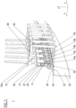
- FIG. 6 to 9 a third embodiment of an inventive transmission welding apparatus 1 is shown.
- the third embodiment 1 is adapted to create convex or concave joints, known from aircraft frames 42, for instance.
- the large pressure plate 14 extends in longitudinal direction x and has linked plate segments 14a, 14b, 14c, 14d. Thereby, only every second plate segment 14a, 14b is pressure activated directly via rods 20a, 20b, 20c, 20d (active plate segments). Plate segments 14c, 14d between these active plate segments 14a, 14b are linked with them via rotational joints 44a, 44b and are being moved passively (passive plate segments). Each rotational joint 44a, 44b enables a rotational movement around a horizontal axis.
- Both active and passive plate segments 14a, 14b, 14c, 14d are made of a transparent material permeable to infrared radiation. Further on, here four rods 20a, 20b, 20c, 20d per active plate segment 14a, 14b are provided, only one guiding means 28 and one gliding element 22 as movable bottom of a pressure generator housing 26 driven by a pressure generator such as a pressure tube 12.
- Each pressure device 10, 10a is positioned in a single holding frame 45.
- Each holding frame 45 has two parallel legs 46, 48, which extend in horizontal direction y.
- the lower leg 46 is used as a counterbearing adapted to be positioned on a lower side 48 of a flange 50 to be processed.
- the upper leg 48 is used to guide and carry the pressure device 10, 10a on an upper side 52 of the flange 50 to be processed in vertical direction z.
- a single heat source 8 is positioned in a channel 24 between the row of rods 20a to 20d and extends over the entire length of the welding apparatus 1 and thus over the entire segmented pressure plate 14.
- the heat source 8 has a cylindrical shape and is positioned in a separate carrier 56.
- the carrier 56 has a longitudinal beam 58 which is pivotable supported in a front slide 60 and in a rear slide 62 in order to balance the convex or concave curvature of the material parts 4, 6. Both pivotable joints enable a rotational movement around a horizontal axis.
- the slides 60, 62 are laid on the upper flange side 54 via their underside.
- the heat source 8 is also supported pivotable in the slides 60, 62.
- a thermal radiation shielding 35 is provided and a thermal protection element 38a which is split in several parts 38c, 38d according to the pressure devices 10, 10b. Between the pressure devices 10, 10b, the thermal protection parts 38d are extended in vertical direction z, thus minimizing gaps between their adjacent pressure generator housings 26, 26a.
- the transmission welding apparatus 1 is moved forward in longitudinal direction x under the application of heat and pressure. During the welding process, the plate segments 14a to 14d are pressed down. When a joint portion (sequence) is made, the pressure is reduced and the welding apparatus 1 is moved forward. Then, the pressure arises again and a next joint sequence is done.
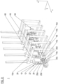
- each unit 36 has one pressure plate segments 14a which is moved by two pressure generators 12, 12a. Further on, a pressure transmission system 16 without rods is provided. Furthermore, each plate segment 14a is equipped with an own heat source 8.
- Each pressure generator 12, 12a has a pressure generator housing 26, 26a which is split in a lower half 64a and in an upper half 64b.
- the lower half 64a is supported by a slide 66 carrying the plate segment 14 and the heat source 8.
- a pneumatic pressure tube 12, 12a is provided inside each generator housing 26, 26a . When the pressure tubes 12, 12a expands, the lower half 64a is moved downwards and a welding pressure is applied to the slide 66 on the plate segment 14a.
- the heat source is orientated perpendicular to the moving direction x of the transmission welding apparatus 1.
- the heating source 8 is orientated in horizontal direction y.
- the heating source 8 is fixed in holding elements 34a, 34b at its end inside the slide 66 above the respective plate segment.
- two vibration element 68a, 68b can be provided in the slide 66.
- the entire joint can also be done in one step and not sequentially in several steps. This depends on the size of the joint, on the size of the transmission welding apparatus and on the contour of the parts to be welded. Welding the material parts in one step can be advantage if the material parts have very complex contours as then every single plate segment can be adapted perfectly with its lower pressing surface perfectly to a respective very complex area.
- a transmission welding apparatus for welding thermoplastic resin material parts, wherein a pressure plate is segmented into a plurality of plate segments which are arranged movable relative to one another, and a welding method.
Landscapes
- Engineering & Computer Science (AREA)
- Mechanical Engineering (AREA)
- Physics & Mathematics (AREA)
- Electromagnetism (AREA)
- Health & Medical Sciences (AREA)
- Toxicology (AREA)
- Fluid Mechanics (AREA)
- Lining Or Joining Of Plastics Or The Like (AREA)
Abstract
Disclosed are a transmission welding apparatus for welding thermoplastic resin material parts, wherein a pressure plate is segmented into a plurality of plate segments which are arranged movable relative to one another, and a welding method.
Description
- The present invention concerns a transmission welding apparatus for welding thermoplastic resin material parts and a method for transmission welding thermoplastic resin material parts.
- Transmission welding is a joining process by means of heat and pressure. Plastic material parts are joint by melting the interface between them and pressing them together. The heat is generated by laser radiation or infrared radiation. The pressure is applied via a transparent pressure plate driven by a pneumatic or hydraulic pressure generator. This process is well known for small parts. An exemplary welding method using infrared is described in the EP-patent application of the applicant
EP 3 953 153 A1 . - It is an object of the present invention to provide a transmission welding apparatus and applicable for welding large material parts and an adequate transmission welding method.
- The object is achieved by a transmission welding apparatus with the features of
claim 1, and by a transmission welding method with the features of claim 9. Advantageous embodiments are disclosed in the dependent claims, the description, and the drawings. - A transmission welding apparatus for welding thermoplastic resin material parts according to the invention comprises at least one heat source emitting thermal radiation and at least one pressure device adapted to apply a welding pressure on the material parts. The pressure device comprises at least one pressure generator for supplying a pressure force, at least one pressure plate which is permeable to the thermal radiation and which is adapted to introduce the pressure force into the material parts, and at least on pressure transmission system for transferring the pressure force to the pressure plate. At least one pressure plate is segmented into a plurality of plate segments which are arranged movable relative to one another.
- According to the invention, a method for transmission welding thermoplastic resin material parts uses an inventive welding apparatus.
- The segmentation of a large pressure plate in a plurality of small plate segments enables a transmission welding of large material parts. The pressure segments can follow individually a local contour of the material parts. The plate segments are located on the material parts to be joined and follow their upper surface during the entire welding cycle inclusive compensation of thermal extension as well as deformations during the welding process.
- Splitting of a single pressure plates allows to perform the welding of the material parts with thickness variation in one short without changing or adaptation of the welding apparatus. This is very beneficial for welding with compensation of tolerances between the joined parts. Even curved material parts can be joint. Exemplary applications in the aircraft industry are the welding of stringers or doublers with ramps or thicknesses variation, of the stringers for fuselage, of for wing and empennage, of longitudinal joints, of circumferential joints, of components to bigger parts, e.g. for pressure bulk head, of movables or of frames. Exemplary heating sources are infrared lamps and halogen lamps emitting 1/3 of visible light and 2/3 of infrared light.
- For instance, if convex or concave joints are processed, due to working space reasons, it can be advantageously if not every plate segment is pressure activated directly. For instance, the plate segments can be linked to another, this enabling a pressure activation of every second plate segment directly, whereas a plate segment between two active plate segments is moved passively via its rotational connection with the adjacent active plate segments.
- In a preferred embodiment, plate segments are in operation connection with the same pressure generator. By means of this, only a single pressure generator is necessary.
- In an alternative embodiment plate segments are in operation connection with an individual pressure generator. By means of this, the plate segment can be positioned in a very flexible manner to each other as they all have their own pressure generator.
- An exemplary pressure transmission comprises rods and at least one gliding element of a pressure generator housing. The rods extend between the at least one gliding element and the plate segments. Preferably, the rods are positioned on opposite edge portions of a plate segment thus avoiding a tilting of the plate segment when the pressure is applied.
- In order to support the rods, guiding means for guiding the rods are provided.
- The at least one heat source can be positioned between the rods. By means of this, the heat source is positioned close to the plate segments.
- Preferably, the heat source has such a length that it extends over all plate segments. In one embodiment, two parallel heat sources are provided. In order to support the heat source at their end, sliding elements can be provided which carry the heat source and slide over the upper material part during welding.
- In order to avoid that material parts areas which are adjacent to the welding area are heated up, at least one thermal protection element is provided.
- In a preferred transmission welding method, a welding joint is made sequentially by moving the welding apparatus forward after a joint section is made. This enables the creating of joints which are longer than the transmission welding apparatus, in particular the extension of its plate segments in the direction of the joint.
- In what follows, preferred embodiments of the present invention are explained with respect to the accompanying drawings. As is to be understood, the various elements and components are depicted as examples only, may be facultative and/or combined in a manner different than that depicted. Moreover, for conciseness reasons, components which evidently correspond to each other are not always described or referenced again for each figure. Shown is schematically in
- Figure 1 to 4:
- different views of a first transmission welding apparatus according to the invention;
- Figure 5:
- a longitudinal section view of a second transmission welding apparatus according to the invention;
- Figure 6 to 9:
- different views of a third transmission welding apparatus according to the invention; and
- Figure 10 to 12:
- different views of a fourth transmission welding apparatus according to the invention;
- In
Figures 1 to 4 a first embodiment of an inventivetransmission welding apparatus 1 is shown. Theapparatus 1 is used to create ajoint 2 at an interface between twomaterial parts 4, 6 via heat and pressure.Exemplary material parts 4, 6 are thermoplastic resin material parts, in particular fibre reinforced thermoplastic parts. - The
apparatus 1 has a main extension in its moving direction, which is the longitudinal direction x of thejoint 2. Theapparatus 1 comprises oneheat source 8 emitting thermal radiation, in particular infrared light, and onepressure device 10 adapted to apply a welding pressure on thematerial parts 4, 6. Anexemplary heat source 8 is an infrared lamp or a halogen lamp. - The
pressure device 10 comprises apressure generator 12 for supplying a pressure force, a segmentedpressure plate 14 which is adapted to introduce the pressure force into thematerial parts 4, 6, and one pressure transmission system 16 for transferring the pressure force to the segmentedpressure plate 14. - The segmented
pressure plate 14 is split into a plurality ofplate segments 18. Theplate segments pressure generator 12 via the pressure transmission system 16. They are movable relative to one another in vertical direction z. They are made of a material that is permeable to thermal radiation such as transparent glass. They have a greater extension in a direction perpendicular to thejoint 2 to be made (horizontal direction y) than in longitudinal direction x. - The pressure transmission system 16 comprises
several rods gliding element plate segment gliding element rods elements 22 and therespective plate segment rods rods plate segment rods heat source 8 is positioned. - The
gliding elements pressure generator housing 26. They are movable in vertical direction z by pressure application. - Further on, the pressure transmission system comprises guiding means 28a, 28b for supporting the
rods apparatus 1. They fixed laterally in different heights and have a plurality of through-holes rods rod - The
pressure generator 12 comprises a longitudinal pneumatic pressure tube that extends over the entire length of theapparatus 1. Thepressure tube 12 is positioned in thepressure generator housing 26 that enables via its movable bottom (glidingelements pressure tube 12 only in a lower vertical direction z. - The
heat source 8 has a cylindrical shape and extends over allplate segments heat source 8 is fixed inside the channel 24 (space between the opposite rods) and carried by two holding elements 34 at its end inside thewelding apparatus 1. Here, the holding elements 34 are attached to the lower guiding means 28a. In order to concentrate the thermal radiation to theplate segments heat source 8 aconcave shielding 35 is positioned extending over the entire length of theplate segments - In order to avoid a heating up of
material part areas welding area 18, in longitudinal direction x on both sidesthermal protection elements thermal protection elements heat source 8 and theplate segments material parts 4, 6. - In order to carry the
transmission welding apparatus 1 in a position, when theplate segments side walls side walls pressure generator housing 26 rests. The guiding means 28a, 28b are also rests on theside walls side wall - In order to create the joint 2, the
transmission welding apparatus 1 is moved forward in longitudinal direction x under the application of heat and pressure. During the welding process, theplate segments welding apparatus 1 is moved forward. Then, the pressure arises again and a next joint sequence is done. - In
Figure 5 a second embodiment of an inventivetransmission welding apparatus 1 shown. Contrary to thefirst welding apparatus 1 according toFigures 1 and4 , the second embodiment has twoheat sources heat sources channel 24 between the row ofrods concave shielding 35 extends over bothheat sources - In
Figures 6 to 9 a third embodiment of an inventivetransmission welding apparatus 1 is shown. Thethird embodiment 1 is adapted to create convex or concave joints, known from aircraft frames 42, for instance. - It comprises a plurality of
pressure devices plate segment large pressure plate 14. Thelarge pressure plate 14 extends in longitudinal direction x and has linkedplate segments second plate segment rods Plate segments active plate segments rotational joints passive plate segments rods active plate segment gliding element 22 as movable bottom of apressure generator housing 26 driven by a pressure generator such as apressure tube 12. - Each
pressure device single holding frame 45. Each holdingframe 45 has twoparallel legs lower leg 46 is used as a counterbearing adapted to be positioned on alower side 48 of aflange 50 to be processed. Theupper leg 48 is used to guide and carry thepressure device upper side 52 of theflange 50 to be processed in vertical direction z. - A
single heat source 8 is positioned in achannel 24 between the row ofrods 20a to 20d and extends over the entire length of thewelding apparatus 1 and thus over the entiresegmented pressure plate 14. Theheat source 8 has a cylindrical shape and is positioned in aseparate carrier 56. Thecarrier 56 has alongitudinal beam 58 which is pivotable supported in afront slide 60 and in arear slide 62 in order to balance the convex or concave curvature of thematerial parts 4, 6. Both pivotable joints enable a rotational movement around a horizontal axis. During welding, theslides upper flange side 54 via their underside. Theheat source 8 is also supported pivotable in theslides - Further on, a thermal radiation shielding 35 is provided and a
thermal protection element 38a which is split in several parts 38c, 38d according to thepressure devices pressure devices pressure generator housings - In order to create a transmission welded joint 2, the
transmission welding apparatus 1 is moved forward in longitudinal direction x under the application of heat and pressure. During the welding process, theplate segments 14a to 14d are pressed down. When a joint portion (sequence) is made, the pressure is reduced and thewelding apparatus 1 is moved forward. Then, the pressure arises again and a next joint sequence is done. - In
Figures 10 to 12 aunit 63 of a fourth embodiment of an inventivetransmission welding apparatus 1 is shown. Thefourth embodiment 1 comprisesmultiple units 63, wherein each unit 36 has onepressure plate segments 14a which is moved by twopressure generators plate segment 14a is equipped with anown heat source 8. - Each
pressure generator pressure generator housing lower half 64a and in anupper half 64b. Thelower half 64a is supported by aslide 66 carrying theplate segment 14 and theheat source 8. Inside eachgenerator housing pneumatic pressure tube pressure tubes lower half 64a is moved downwards and a welding pressure is applied to theslide 66 on theplate segment 14a. - The heat source is orientated perpendicular to the moving direction x of the
transmission welding apparatus 1. Thus, theheating source 8 is orientated in horizontal direction y. Theheating source 8 is fixed in holdingelements slide 66 above the respective plate segment. - In order to optimize the welding process, laterally to the
plate segment 14a twovibration element slide 66. - In order to create a transmission welded joint,
several units 63 are arranged adjacent to another in longitudinal direction x to onewelding apparatus 1 and then moved forward under heat, pressure and vibration application. During the welding process, theplate segments 14a are pressed down. When a joint portion (sequence) is made, the pressure is reduced and the welding apparatus is moved forward. Then, the pressure arises again and a next joint sequence is done. - It should be noted that regarding all embodiments, the entire joint can also be done in one step and not sequentially in several steps. This depends on the size of the joint, on the size of the transmission welding apparatus and on the contour of the parts to be welded. Welding the material parts in one step can be advantage if the material parts have very complex contours as then every single plate segment can be adapted perfectly with its lower pressing surface perfectly to a respective very complex area.
- Disclosed are a transmission welding apparatus for welding thermoplastic resin material parts, wherein a pressure plate is segmented into a plurality of plate segments which are arranged movable relative to one another, and a welding method.
-
- 1 transmission welding apparatus / apparatus
- 2 joint
- 4 material part
- 6 material part
- 8, a heat source
- 10, a pressure device
- 12, a pressure generator / pressure tube
- 14 segmented pressure plate
- 16 pressure transmission system
- 14a, b plate segment (active)
- 14c, d plate segment (passive)
- 18 welding area
- 20a, b rod
- 22, a, b gliding element
- 24 channel
- 26, a pressure generator housing
- 28, a, b guiding means
- 30a, b through-hole
- 34a, b holding element
- 35 shielding
- 36a, b material part area
- 38a, b thermal protection element
- 40a, b side wall
- 42 frame
- 44a, b rotational joint
- 45 holding frame
- 46 lower leg
- 48 upper leg
- 50 flange
- 52 lower side
- 54 upper side
- 56 carrier
- 58 longitudinal beam
- 60 front slide
- 62 rear slide
- 63 unit
- 64a lower half of generator housing
- 64b upper half of generator housing
- 66 slide
- 68, b vibration element
- x longitudinal direction
- y horizontal direction
- z vertical direction
Claims (10)
- A transmission welding apparatus (1) for welding thermoplastic resin material parts (4, 6), comprising:o at least one heat source (8, 8a) emitting thermal radiation;o at least one pressure device (10, 10a) adapted to apply a welding pressure on the material parts, comprisingwherein the at least one pressure plate (14) is segmented into a plurality of plate segments (14a, 14b, 14c, 14d) which are arranged movable relative to one another.▪ at least one pressure generator (12, 12a) for supplying a pressure force;▪ at least one pressure plate (14) which is permeable to the thermal radiation and which is adapted to introduce the pressure force into the material parts; and▪ at least one pressure transmission (16) system for transferring the pressure force to the pressure plate (14);
- The transmission welding apparatus (1) according to claim 1, wherein the plate segments (14a, 14b, 14c, 14d) are rotationally linked with another.
- The transmission welding apparatus (1) according to claims 1 or 2, wherein plate segments (14a, 14b, 14c, 14d) are in operation connection with the same pressure generator (12) or with individual pressure generators (12, 12a).
- The transmission welding apparatus (1) according to claims 1, 2 or 3, wherein the at least one pressure transmission comprises rods (20a, 20b, 20c, 20d) and at least one gliding element (22, 22a, 22b) of a pressure generator housing (26), wherein the rods (20a, 20b, 20c, 20d) extend between the at least one gliding element and the plate segments (14a, 14b, 14c, 14d).
- The transmission welding apparatus (1) according to claim 4, wherein guiding means (28, 28a, 28b) are provided adapted for guiding the rods (20a, 20b, 20c, 20d).
- The transmission welding apparatus (1) according to claim 6, wherein the at least one heat source (8, 8a) is positioned between the rods (20a, 20b, 20c, 20d).
- The transmission welding apparatus (1) according to claim 6, wherein the heat source (8, 8a) extends over all plate segments (14a, 14b, 14c, 14d).
- The transmission welding apparatus (1) according to any of the preceding claims, wherein in moving direction of the transmission welding apparatus (1) at least one thermal protection element (38a, 38b) is provided.
- A method for transmission welding thermoplastic resin material parts (4, 6), using a transmission welding apparatus (1) according to any of the preceding claims.
- The method according to claim 9, wherein a welding joint (2) is made sequentially by moving the transmission welding apparatus, (1) forward after a joint section is made.
Priority Applications (3)
| Application Number | Priority Date | Filing Date | Title |
|---|---|---|---|
| EP23217984.6A EP4574401A1 (en) | 2023-12-19 | 2023-12-19 | Transmission welding apparatus and welding method |
| US18/978,629 US20250196448A1 (en) | 2023-12-19 | 2024-12-12 | Transmission welding apparatus and welding method |
| CN202411851199.9A CN120171055A (en) | 2023-12-19 | 2024-12-16 | Transmission welding equipment and welding method |
Applications Claiming Priority (1)
| Application Number | Priority Date | Filing Date | Title |
|---|---|---|---|
| EP23217984.6A EP4574401A1 (en) | 2023-12-19 | 2023-12-19 | Transmission welding apparatus and welding method |
Publications (1)
| Publication Number | Publication Date |
|---|---|
| EP4574401A1 true EP4574401A1 (en) | 2025-06-25 |
Family
ID=89224160
Family Applications (1)
| Application Number | Title | Priority Date | Filing Date |
|---|---|---|---|
| EP23217984.6A Pending EP4574401A1 (en) | 2023-12-19 | 2023-12-19 | Transmission welding apparatus and welding method |
Country Status (3)
| Country | Link |
|---|---|
| US (1) | US20250196448A1 (en) |
| EP (1) | EP4574401A1 (en) |
| CN (1) | CN120171055A (en) |
Citations (3)
| Publication number | Priority date | Publication date | Assignee | Title |
|---|---|---|---|---|
| US20050039855A1 (en) * | 2003-08-22 | 2005-02-24 | Jie-Wei Chen | Apparatus for connecting planar plastic materials |
| US20130025793A1 (en) * | 2010-03-24 | 2013-01-31 | Innoptics | Device for welding thermoplastic membranes |
| EP3953153A1 (en) | 2019-07-30 | 2022-02-16 | Airbus Operations GmbH | Transmission welding method, transmission welding device and transmission welding arrangement |
Family Cites Families (1)
| Publication number | Priority date | Publication date | Assignee | Title |
|---|---|---|---|---|
| DE4204041C2 (en) * | 1992-02-12 | 1994-03-03 | 2 H Kunststoff Gmbh | Method for producing a built-in element for heat exchanger, mass exchanger and / or bioreactor systems and device for carrying out the method |
-
2023
- 2023-12-19 EP EP23217984.6A patent/EP4574401A1/en active Pending
-
2024
- 2024-12-12 US US18/978,629 patent/US20250196448A1/en active Pending
- 2024-12-16 CN CN202411851199.9A patent/CN120171055A/en active Pending
Patent Citations (3)
| Publication number | Priority date | Publication date | Assignee | Title |
|---|---|---|---|---|
| US20050039855A1 (en) * | 2003-08-22 | 2005-02-24 | Jie-Wei Chen | Apparatus for connecting planar plastic materials |
| US20130025793A1 (en) * | 2010-03-24 | 2013-01-31 | Innoptics | Device for welding thermoplastic membranes |
| EP3953153A1 (en) | 2019-07-30 | 2022-02-16 | Airbus Operations GmbH | Transmission welding method, transmission welding device and transmission welding arrangement |
Also Published As
| Publication number | Publication date |
|---|---|
| CN120171055A (en) | 2025-06-20 |
| US20250196448A1 (en) | 2025-06-19 |
Similar Documents
| Publication | Publication Date | Title |
|---|---|---|
| US5616261A (en) | Laser welding system | |
| JP2839812B2 (en) | Method and apparatus for making a structural reinforcement preform including energy basting of a web of reinforcement and energy stitching of a reinforcement member | |
| US5064991A (en) | Device for laser welding motor-vehicle bodies | |
| EP1211014B1 (en) | Device and method for seam welding | |
| US20100038024A1 (en) | Method and device for positioning stringers on an aircraft skin, in particular on a wing skin | |
| JP3856777B2 (en) | Article processing method and apparatus | |
| EP1000696B1 (en) | Friction welder | |
| EP0620091B1 (en) | Method and apparatus for making structural reinforcement preforms including energetic basting and stitching | |
| US11518112B2 (en) | Joining method and machining head and manufacturing machine for carrying out the method | |
| CN107471655A (en) | For manufacturing the method and device of the structure member applied to aircraft or spacecraft | |
| US8263902B2 (en) | Laser-scribing system for structuring substrates for thin layer solar modules | |
| US8887544B2 (en) | Conveyor apparatus and hot press-forming apparatus comprising the same | |
| EP0061183A1 (en) | Process for obtaining a strong bond of insulating glass panes | |
| US20050039855A1 (en) | Apparatus for connecting planar plastic materials | |
| KR19990072430A (en) | A method of drawing fiber continuously from preforms for manufacturing optical fibers | |
| US20250196448A1 (en) | Transmission welding apparatus and welding method | |
| US11701839B2 (en) | Method and system for joining two components of a meltable material | |
| CN114516410A (en) | Aircraft assembly formed of mating semi-cylindrical sections and method of assembling same | |
| US10046846B2 (en) | Method for manufacturing a shell component for an aircraft or spacecraft | |
| EP4292728B1 (en) | Molding device and metal pipe | |
| CN104999661A (en) | Synchronous laser welding process and device | |
| DE102019215516B4 (en) | Device for cohesively connecting two work pieces made of plastic by means of laser welding | |
| ZA200102560B (en) | Method and plant for continously producing construction elements. | |
| KR20030083917A (en) | pipe clamping apparatus with heater separating device | |
| US6897404B2 (en) | Method and device for welding contacts to optical waveguides |
Legal Events
| Date | Code | Title | Description |
|---|---|---|---|
| PUAI | Public reference made under article 153(3) epc to a published international application that has entered the european phase |
Free format text: ORIGINAL CODE: 0009012 |
|
| STAA | Information on the status of an ep patent application or granted ep patent |
Free format text: STATUS: THE APPLICATION HAS BEEN PUBLISHED |
|
| AK | Designated contracting states |
Kind code of ref document: A1 Designated state(s): AL AT BE BG CH CY CZ DE DK EE ES FI FR GB GR HR HU IE IS IT LI LT LU LV MC ME MK MT NL NO PL PT RO RS SE SI SK SM TR |
|
| STAA | Information on the status of an ep patent application or granted ep patent |
Free format text: STATUS: REQUEST FOR EXAMINATION WAS MADE |
|
| 17P | Request for examination filed |
Effective date: 20251217 |