EP4574361A2 - Food product slicer and associated knife assembly - Google Patents
Food product slicer and associated knife assembly Download PDFInfo
- Publication number
- EP4574361A2 EP4574361A2 EP24219576.6A EP24219576A EP4574361A2 EP 4574361 A2 EP4574361 A2 EP 4574361A2 EP 24219576 A EP24219576 A EP 24219576A EP 4574361 A2 EP4574361 A2 EP 4574361A2
- Authority
- EP
- European Patent Office
- Prior art keywords
- knife
- food product
- mount
- product slicer
- cover plate
- Prior art date
- Legal status (The legal status is an assumption and is not a legal conclusion. Google has not performed a legal analysis and makes no representation as to the accuracy of the status listed.)
- Pending
Links
Images









Classifications
-
- B—PERFORMING OPERATIONS; TRANSPORTING
- B26—HAND CUTTING TOOLS; CUTTING; SEVERING
- B26D—CUTTING; DETAILS COMMON TO MACHINES FOR PERFORATING, PUNCHING, CUTTING-OUT, STAMPING-OUT OR SEVERING
- B26D3/00—Cutting work characterised by the nature of the cut made; Apparatus therefor
- B26D3/28—Splitting layers from work; Mutually separating layers by cutting
-
- B—PERFORMING OPERATIONS; TRANSPORTING
- B24—GRINDING; POLISHING
- B24D—TOOLS FOR GRINDING, BUFFING OR SHARPENING
- B24D15/00—Hand tools or other devices for non-rotary grinding, polishing, or stropping
- B24D15/06—Hand tools or other devices for non-rotary grinding, polishing, or stropping specially designed for sharpening cutting edges
- B24D15/08—Hand tools or other devices for non-rotary grinding, polishing, or stropping specially designed for sharpening cutting edges of knives; of razors
-
- B—PERFORMING OPERATIONS; TRANSPORTING
- B26—HAND CUTTING TOOLS; CUTTING; SEVERING
- B26D—CUTTING; DETAILS COMMON TO MACHINES FOR PERFORATING, PUNCHING, CUTTING-OUT, STAMPING-OUT OR SEVERING
- B26D1/00—Cutting through work characterised by the nature or movement of the cutting member or particular materials not otherwise provided for; Apparatus or machines therefor; Cutting members therefor
- B26D1/01—Cutting through work characterised by the nature or movement of the cutting member or particular materials not otherwise provided for; Apparatus or machines therefor; Cutting members therefor involving a cutting member which does not travel with the work
- B26D1/12—Cutting through work characterised by the nature or movement of the cutting member or particular materials not otherwise provided for; Apparatus or machines therefor; Cutting members therefor involving a cutting member which does not travel with the work having a cutting member moving about an axis
- B26D1/14—Cutting through work characterised by the nature or movement of the cutting member or particular materials not otherwise provided for; Apparatus or machines therefor; Cutting members therefor involving a cutting member which does not travel with the work having a cutting member moving about an axis with a circular cutting member, e.g. disc cutter
- B26D1/143—Cutting through work characterised by the nature or movement of the cutting member or particular materials not otherwise provided for; Apparatus or machines therefor; Cutting members therefor involving a cutting member which does not travel with the work having a cutting member moving about an axis with a circular cutting member, e.g. disc cutter rotating about a stationary axis
- B26D1/15—Cutting through work characterised by the nature or movement of the cutting member or particular materials not otherwise provided for; Apparatus or machines therefor; Cutting members therefor involving a cutting member which does not travel with the work having a cutting member moving about an axis with a circular cutting member, e.g. disc cutter rotating about a stationary axis with vertical cutting member
-
- B—PERFORMING OPERATIONS; TRANSPORTING
- B26—HAND CUTTING TOOLS; CUTTING; SEVERING
- B26D—CUTTING; DETAILS COMMON TO MACHINES FOR PERFORATING, PUNCHING, CUTTING-OUT, STAMPING-OUT OR SEVERING
- B26D5/00—Arrangements for operating and controlling machines or devices for cutting, cutting-out, stamping-out, punching, perforating, or severing by means other than cutting
- B26D5/08—Means for actuating the cutting member to effect the cut
- B26D5/086—Electric, magnetic, piezoelectric, electro-magnetic means
-
- B—PERFORMING OPERATIONS; TRANSPORTING
- B26—HAND CUTTING TOOLS; CUTTING; SEVERING
- B26D—CUTTING; DETAILS COMMON TO MACHINES FOR PERFORATING, PUNCHING, CUTTING-OUT, STAMPING-OUT OR SEVERING
- B26D7/00—Details of apparatus for cutting, cutting-out, stamping-out, punching, perforating, or severing by means other than cutting
-
- B—PERFORMING OPERATIONS; TRANSPORTING
- B26—HAND CUTTING TOOLS; CUTTING; SEVERING
- B26D—CUTTING; DETAILS COMMON TO MACHINES FOR PERFORATING, PUNCHING, CUTTING-OUT, STAMPING-OUT OR SEVERING
- B26D7/00—Details of apparatus for cutting, cutting-out, stamping-out, punching, perforating, or severing by means other than cutting
- B26D7/06—Arrangements for feeding or delivering work of other than sheet, web, or filamentary form
- B26D7/0616—Arrangements for feeding or delivering work of other than sheet, web, or filamentary form by carriages, e.g. for slicing machines
-
- B—PERFORMING OPERATIONS; TRANSPORTING
- B26—HAND CUTTING TOOLS; CUTTING; SEVERING
- B26D—CUTTING; DETAILS COMMON TO MACHINES FOR PERFORATING, PUNCHING, CUTTING-OUT, STAMPING-OUT OR SEVERING
- B26D7/00—Details of apparatus for cutting, cutting-out, stamping-out, punching, perforating, or severing by means other than cutting
- B26D7/08—Means for treating work or cutting member to facilitate cutting
- B26D7/12—Means for treating work or cutting member to facilitate cutting by sharpening the cutting member
-
- B—PERFORMING OPERATIONS; TRANSPORTING
- B26—HAND CUTTING TOOLS; CUTTING; SEVERING
- B26D—CUTTING; DETAILS COMMON TO MACHINES FOR PERFORATING, PUNCHING, CUTTING-OUT, STAMPING-OUT OR SEVERING
- B26D7/00—Details of apparatus for cutting, cutting-out, stamping-out, punching, perforating, or severing by means other than cutting
- B26D7/26—Means for mounting or adjusting the cutting member; Means for adjusting the stroke of the cutting member
- B26D7/2614—Means for mounting the cutting member
- B26D7/2621—Means for mounting the cutting member for circular cutters
-
- B—PERFORMING OPERATIONS; TRANSPORTING
- B26—HAND CUTTING TOOLS; CUTTING; SEVERING
- B26D—CUTTING; DETAILS COMMON TO MACHINES FOR PERFORATING, PUNCHING, CUTTING-OUT, STAMPING-OUT OR SEVERING
- B26D7/00—Details of apparatus for cutting, cutting-out, stamping-out, punching, perforating, or severing by means other than cutting
- B26D7/26—Means for mounting or adjusting the cutting member; Means for adjusting the stroke of the cutting member
- B26D7/2628—Means for adjusting the position of the cutting member
- B26D7/2635—Means for adjusting the position of the cutting member for circular cutters
-
- B—PERFORMING OPERATIONS; TRANSPORTING
- B26—HAND CUTTING TOOLS; CUTTING; SEVERING
- B26D—CUTTING; DETAILS COMMON TO MACHINES FOR PERFORATING, PUNCHING, CUTTING-OUT, STAMPING-OUT OR SEVERING
- B26D1/00—Cutting through work characterised by the nature or movement of the cutting member or particular materials not otherwise provided for; Apparatus or machines therefor; Cutting members therefor
- B26D1/01—Cutting through work characterised by the nature or movement of the cutting member or particular materials not otherwise provided for; Apparatus or machines therefor; Cutting members therefor involving a cutting member which does not travel with the work
- B26D1/12—Cutting through work characterised by the nature or movement of the cutting member or particular materials not otherwise provided for; Apparatus or machines therefor; Cutting members therefor involving a cutting member which does not travel with the work having a cutting member moving about an axis
- B26D1/14—Cutting through work characterised by the nature or movement of the cutting member or particular materials not otherwise provided for; Apparatus or machines therefor; Cutting members therefor involving a cutting member which does not travel with the work having a cutting member moving about an axis with a circular cutting member, e.g. disc cutter
- B26D1/143—Cutting through work characterised by the nature or movement of the cutting member or particular materials not otherwise provided for; Apparatus or machines therefor; Cutting members therefor involving a cutting member which does not travel with the work having a cutting member moving about an axis with a circular cutting member, e.g. disc cutter rotating about a stationary axis
-
- B—PERFORMING OPERATIONS; TRANSPORTING
- B26—HAND CUTTING TOOLS; CUTTING; SEVERING
- B26D—CUTTING; DETAILS COMMON TO MACHINES FOR PERFORATING, PUNCHING, CUTTING-OUT, STAMPING-OUT OR SEVERING
- B26D2210/00—Machines or methods used for cutting special materials
- B26D2210/02—Machines or methods used for cutting special materials for cutting food products, e.g. food slicers
-
- B—PERFORMING OPERATIONS; TRANSPORTING
- B26—HAND CUTTING TOOLS; CUTTING; SEVERING
- B26D—CUTTING; DETAILS COMMON TO MACHINES FOR PERFORATING, PUNCHING, CUTTING-OUT, STAMPING-OUT OR SEVERING
- B26D7/00—Details of apparatus for cutting, cutting-out, stamping-out, punching, perforating, or severing by means other than cutting
- B26D7/01—Means for holding or positioning work
-
- B—PERFORMING OPERATIONS; TRANSPORTING
- B26—HAND CUTTING TOOLS; CUTTING; SEVERING
- B26D—CUTTING; DETAILS COMMON TO MACHINES FOR PERFORATING, PUNCHING, CUTTING-OUT, STAMPING-OUT OR SEVERING
- B26D7/00—Details of apparatus for cutting, cutting-out, stamping-out, punching, perforating, or severing by means other than cutting
- B26D7/22—Safety devices specially adapted for cutting machines
- B26D7/225—Safety devices specially adapted for cutting machines for food slicers
Definitions
- This application relates generally to food product slicers of the type commonly used to slice bulk food products and, more specifically, to a food product slicer with a rotatable slicer knife and associated knife cover.
- Typical reciprocating food slicers have a rotatable, circular or disc-like slicing blade, an adjustable gauge plate for determining the thickness of the slice and a carriage for supporting the food as it is moved back and forth past the cutting edge of the knife, and over a knife cover plate, during slicing.
- a drive motor may be linked to drive the carriage back and forth during an automatic slicing operation carried out by a controller of the slicer and/or manual operation is possible.
- the gauge plate is situated along the edge of the knife toward the front of a slicing stroke and is laterally movable with respect to the knife for determining the thickness of the slices to be cut.
- a rotatable adjustment or indexing knob is provided for manually setting a spacing between the plane of the gauge plate surface and the plane of the knife edge for the purpose of slicing so that operators can select a thickness of slices to be produced.
- Such existing slicers must hold a tight tolerance between the knife edge and the knife cover plate in order to achieve good slice quality. If the knife cover plate is too high/low compared to the knife, the knife cover plate will tend to rip/tear product slices or prevent the machine from being able to slice very thin. Typically, there are several parts between the knife and the knife cover plate resulting in a large tolerance stack-up, and the knife cover plate is typically mounted on a ring guard. In order to maintain appropriate slice quality with this large tolerance stack-up, slicers historically have allowed for some ring guard adjustment. This is a relatively fine adjustment to ensure proper slicing function. Machines that do not allow for this adjustment typically suffer from poor slicer performance.
- a food product slicer includes a base, a knife mounted for rotation about an axis relative to the base via a knife drive shaft, and a knife cover plate overlying regions of the knife.
- a monolithic mount part is provided that defines a first mount portion to which the knife drive shaft for the knife is mounted and a second mount portion to which the knife cover plate mounts, so as to establish a relative axial position between the knife and the knife cover plate.
- a food product slicer in another aspect, includes a base, a knife mounted for rotation about an axis relative to the base via a knife drive shaft, a knife cover plate overlying regions of the knife, a carriage assembly mounted to the base for reciprocal movement back and forth past a cutting edge of the knife, and a gauge plate mounted for movement between a closed position that prevents slicing and multiple open positions that permit slicing at respective thicknesses.
- a monolithic mount part is provided that defines a first mount portion to which the knife drive shaft for the knife is mounted and a second mount portion to which the knife cover plate mounts, so as to establish a relative axial position between the knife and the knife cover plate.
- a food product slicer in yet another aspect, includes a base, a knife mounted for rotation about an axis relative to the base via a knife drive shaft, and a knife cover plate overlying regions of the knife.
- a monolithic mount part defines a first mount portion to which the knife drive shaft for the knife is mounted, a second mount portion to which the knife cover plate mounts and a third mount portion that defines a sharpener mount station.
- a food product slicer 10 includes a base 12 and a circular, motor-driven slicing knife 14 that is mounted to the base for rotation about an axis 16.
- the base 12 includes an upper housing 12a and a lower housing 12b.
- the left side of Fig. 1 where the controls are located and an operator is located during slicing, is generally referred to as the front side of the slicer (which is where an operator stands for slicing), and the right side of Fig. 1 is generally referred to as the rear side of the slicer.
- a food product can be supported on a manually operable (or motor driven) food carriage 20 which moves the food product to be sliced past the cutting edge 14a of the rotating slicing knife 14.
- the food carriage 20 reciprocates from left to right relative to Fig. 1 , along a linear path so that the lower end of the bulk food product slides along the surface of a gauge plate 22, is cut by the knife 14 and then slides along a knife cover plate 24.
- Food carriage 20 includes a tray mounted on a tray arm 26 that orients the food carriage tray at the appropriate angle (typically perpendicular) to the knife cutting-edge plane.
- the food carriage arm reciprocates in a slot 28 at a lower portion of an external housing 12a of the base 12.
- the carriage 20 can be moved manually (e.g., by a handle) and/or the carriage 20 may also be automatically driven (e.g., as by an internal motor 29 that drives a belt that is linked internally to the arm).
- a gauge plate system includes a rotatable knob 30 (connected to an opening in the base 12) that includes a grip part 30a and an internal cam part that is linked to the gauge plate 22 such that rotation of the knob 30 effects movement the gauge plate, relative to a plane of the knife edge 14a, to adjust slice thickness.
- the gauge plate 22 moves along an axis that runs parallel to the axis 16, such that the food product contact surface of the gauge plate 22 remains substantially parallel to the plane of the knife edge 14a.
- a knife sharpener assembly 34 is also mounted on the machine and can be manually operated to sharpen the knife edge 14a.
- a single monolithic mount part 40 is provided to serve as both the part to which a drive shaft assembly for the knife 14 mounts and the part to which the knife cover plate 24 mounts.
- the knife itself mounts to part of the knife drive shaft 50.
- the configuration of the mount part 40 therefore defines the relative positioning of the knife cover plate 24 relative to the mount portion of the knife drive shaft 50, including in a direction along the knife axis 16, enabling a tight tolerance to be achieved between the relative position of the knife 14 and knife cover plate 24 after assembly.
- the monolithic part may be single piece unit, rather than multiple pieces connected together.
- the mount part 40 is formed of an aluminum material and is a single cast and machined part, which facilitates precise tolerancing during manufacture.
- the mount part 40 also serves as the part to which the knife sharpener assembly 34 mounts, thereby assuring precise/tight tolerance in the position of the knife sharpener assembly 34 relative to the knife edge 14a.
- the mount part 40 includes a central hub 42 from which spokes 44 run to a peripheral rim 46 that serves as a ring guard cover.
- the position of the mount part 40 on the slicer housing is defined by a rear hub part 42a that fits into a mount opening 12a1 on the upper housing 12a of the base 12.
- the position of a knife drive shaft 50 on the mount part 40 is defined by the opening 42b in the hub part 42, which defines internal annular seats that receive shaft bearing assemblies 52a and 52b, where the shaft segment 50a of knife drive shaft 50 is matingly received within the bearing assemblies 52a, 52b and the mount hub segment 50b seats axially against the bearing assembly 52a.
- the knife 14 then mounts to the knife mount hub 50b of the knife drive shaft 50 (e.g., via fasteners through aligned opening sets 50c and 14b).
- a cup-shaped seal member 45 is also mounted to the mount part 40 to seal against a rear surface of the knife 14.
- the position of the knife cover plate 24 on the mount part 40 is defined by the axially facing rim surface 46a and mount openings 54a-54c thereon, which receive respective cover support/alignment pins 56a-56c, as well as mount opening 54d which receives a threaded support/alignment pin 56d.
- the knife cover plate 24 itself includes an opening 58c that aligns with and slides onto pin 56c, slots 58a-58b that engage onto pins 56a-56b, and an opening 58d that aligns with the threaded pin 56d.
- a removable knob 60 with a threaded opening threadedly engages onto the pin 56d to secure the cover plate 24 in place.
- both the knife 14 and the knife cover plate are both tied to and defined by the configuration of the monolithic mount part 40.
- the mount part 40 includes a knife mount platform 62 with a keyway opening 62a into which a mating key 34a of the sharpener assembly fits to define the position of the sharpener assembly 34, thereby defining a position of the sharpening stone(s) of the sharpener assembly relative to the knife edge.
- a recessed region 46b of the peripheral rim 46 enables the sharpening stone(s) to be moved into contact with the knife edge for knife sharpening.
- the drive assembly for the knife is located internally of the upper housing 12a and includes a motor 70 that drives a belt 72 that turns a pulley 74 that in turn is connected to and rotates the drive shaft 50.
- the motor 70 is mounted to a plate 76 that in turn is secured by fasteners to a mount bracket 77 that is integrated with the upper housing 12a (e.g., monolithic with the upper housing 12a) and includes specified fastener positions 77a.
- the upper housing 12a also includes the opening 12a1 that fits over the rear hub part 42a to establish the position of the integrated bracket 77, and thereby establish the position of the drive components (the plate 76, the motor 70 and its drive shaft) mounted thereon.
- This configuration aids in achieving the desired and necessary spacing between the motor and motor shaft and the knife drive shaft 50, and also enables the knife drive assembly to be built as a sub-assembly (e.g., the motor 70, plate 76 and motor drive shaft formed as a sub-assembly that can be easily mounted to the mount bracket 77).
- the knife drive assembly e.g., the motor 70, plate 76 and motor drive shaft formed as a sub-assembly that can be easily mounted to the mount bracket 77).
- the system provides various advantages, including: fewer parts and lower cost, fewer assembly steps and with no adjustments (lower cost, easier manufacturing, easier to service), consistent tolerance/adjustment during its life, less customer down-time, and allowing both the knife shaft and knife motor parts to be built up as sub-assemblies, increasing the efficiency of machine production.
Landscapes
- Engineering & Computer Science (AREA)
- Mechanical Engineering (AREA)
- Life Sciences & Earth Sciences (AREA)
- Forests & Forestry (AREA)
- Food-Manufacturing Devices (AREA)
- Knives (AREA)
- Details Of Cutting Devices (AREA)
Abstract
Description
- This application relates generally to food product slicers of the type commonly used to slice bulk food products and, more specifically, to a food product slicer with a rotatable slicer knife and associated knife cover.
- Typical reciprocating food slicers have a rotatable, circular or disc-like slicing blade, an adjustable gauge plate for determining the thickness of the slice and a carriage for supporting the food as it is moved back and forth past the cutting edge of the knife, and over a knife cover plate, during slicing. A drive motor may be linked to drive the carriage back and forth during an automatic slicing operation carried out by a controller of the slicer and/or manual operation is possible. The gauge plate is situated along the edge of the knife toward the front of a slicing stroke and is laterally movable with respect to the knife for determining the thickness of the slices to be cut. A rotatable adjustment or indexing knob is provided for manually setting a spacing between the plane of the gauge plate surface and the plane of the knife edge for the purpose of slicing so that operators can select a thickness of slices to be produced.
- Such existing slicers must hold a tight tolerance between the knife edge and the knife cover plate in order to achieve good slice quality. If the knife cover plate is too high/low compared to the knife, the knife cover plate will tend to rip/tear product slices or prevent the machine from being able to slice very thin. Typically, there are several parts between the knife and the knife cover plate resulting in a large tolerance stack-up, and the knife cover plate is typically mounted on a ring guard. In order to maintain appropriate slice quality with this large tolerance stack-up, slicers historically have allowed for some ring guard adjustment. This is a relatively fine adjustment to ensure proper slicing function. Machines that do not allow for this adjustment typically suffer from poor slicer performance.
- It would be desirable to provide a slicer with effective slicing performance without requiring the fine adjustment of the ring guard.
- In one aspect, a food product slicer includes a base, a knife mounted for rotation about an axis relative to the base via a knife drive shaft, and a knife cover plate overlying regions of the knife. A monolithic mount part is provided that defines a first mount portion to which the knife drive shaft for the knife is mounted and a second mount portion to which the knife cover plate mounts, so as to establish a relative axial position between the knife and the knife cover plate.
- In another aspect, a food product slicer includes a base, a knife mounted for rotation about an axis relative to the base via a knife drive shaft, a knife cover plate overlying regions of the knife, a carriage assembly mounted to the base for reciprocal movement back and forth past a cutting edge of the knife, and a gauge plate mounted for movement between a closed position that prevents slicing and multiple open positions that permit slicing at respective thicknesses. A monolithic mount part is provided that defines a first mount portion to which the knife drive shaft for the knife is mounted and a second mount portion to which the knife cover plate mounts, so as to establish a relative axial position between the knife and the knife cover plate.
- In yet another aspect, a food product slicer includes a base, a knife mounted for rotation about an axis relative to the base via a knife drive shaft, and a knife cover plate overlying regions of the knife. A monolithic mount part defines a first mount portion to which the knife drive shaft for the knife is mounted, a second mount portion to which the knife cover plate mounts and a third mount portion that defines a sharpener mount station.
-
-
Figs. 1-4 show perspective views of a food product slicer; -
Fig. 5 shows a perspective view of the slicer base upper housing; -
Figs. 6-7 show perspective views of interior portions of the base showing the slicer knife drive; -
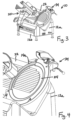
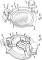
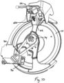
Figs. 8A-8D and10 show perspective views of a knife assembly and associated knife drive of the food product slicer, whereFigs. 8C-8D show components exploded away from each other; -
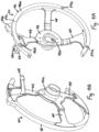
Figs. 9A-9B show perspective views of a monolithic mount part of the knife assembly; -
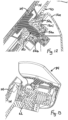
Figs. 11A-11E show perspective views of portion of a sharpener assembly; -
Fig. 12 shows a cross-section of knife mounting on the slicer housing; -
Fig. 13 shows a cross-section of the sharpener assembly; and -
Fig. 14 shows a cross-section of a securing knob for the knife cover plate. - Referring to
Figs. 1-14 , a food product slicer 10 includes abase 12 and a circular, motor-drivenslicing knife 14 that is mounted to the base for rotation about an axis 16. Here, thebase 12 includes anupper housing 12a and a lower housing 12b. The left side ofFig. 1 , where the controls are located and an operator is located during slicing, is generally referred to as the front side of the slicer (which is where an operator stands for slicing), and the right side ofFig. 1 is generally referred to as the rear side of the slicer. A food product can be supported on a manually operable (or motor driven)food carriage 20 which moves the food product to be sliced past thecutting edge 14a of the rotatingslicing knife 14. Thefood carriage 20 reciprocates from left to right relative toFig. 1 , along a linear path so that the lower end of the bulk food product slides along the surface of agauge plate 22, is cut by theknife 14 and then slides along aknife cover plate 24.Food carriage 20 includes a tray mounted on atray arm 26 that orients the food carriage tray at the appropriate angle (typically perpendicular) to the knife cutting-edge plane. The food carriage arm reciprocates in aslot 28 at a lower portion of anexternal housing 12a of thebase 12. Thecarriage 20 can be moved manually (e.g., by a handle) and/or thecarriage 20 may also be automatically driven (e.g., as by aninternal motor 29 that drives a belt that is linked internally to the arm). A gauge plate system includes a rotatable knob 30 (connected to an opening in the base 12) that includes agrip part 30a and an internal cam part that is linked to thegauge plate 22 such that rotation of the knob 30 effects movement the gauge plate, relative to a plane of theknife edge 14a, to adjust slice thickness. Generally, thegauge plate 22 moves along an axis that runs parallel to the axis 16, such that the food product contact surface of thegauge plate 22 remains substantially parallel to the plane of theknife edge 14a. Aknife sharpener assembly 34 is also mounted on the machine and can be manually operated to sharpen theknife edge 14a. - A single
monolithic mount part 40 is provided to serve as both the part to which a drive shaft assembly for theknife 14 mounts and the part to which theknife cover plate 24 mounts. The knife itself mounts to part of the knife drive shaft 50. The configuration of themount part 40 therefore defines the relative positioning of theknife cover plate 24 relative to the mount portion of the knife drive shaft 50, including in a direction along the knife axis 16, enabling a tight tolerance to be achieved between the relative position of theknife 14 andknife cover plate 24 after assembly. The monolithic part may be single piece unit, rather than multiple pieces connected together. In one example, themount part 40 is formed of an aluminum material and is a single cast and machined part, which facilitates precise tolerancing during manufacture. Here, themount part 40 also serves as the part to which theknife sharpener assembly 34 mounts, thereby assuring precise/tight tolerance in the position of theknife sharpener assembly 34 relative to theknife edge 14a. - The
mount part 40 includes acentral hub 42 from whichspokes 44 run to aperipheral rim 46 that serves as a ring guard cover. The position of themount part 40 on the slicer housing is defined by arear hub part 42a that fits into a mount opening 12a1 on theupper housing 12a of thebase 12. The position of a knife drive shaft 50 on themount part 40 is defined by the opening 42b in thehub part 42, which defines internal annular seats that receive shaft bearingassemblies 52a and 52b, where the shaft segment 50a of knife drive shaft 50 is matingly received within thebearing assemblies 52a, 52b and the mount hub segment 50b seats axially against the bearing assembly 52a. Theknife 14 then mounts to the knife mount hub 50b of the knife drive shaft 50 (e.g., via fasteners through alignedopening sets shaped seal member 45 is also mounted to themount part 40 to seal against a rear surface of theknife 14. - The position of the
knife cover plate 24 on themount part 40 is defined by the axially facing rim surface 46a andmount openings 54a-54c thereon, which receive respective cover support/alignment pins 56a-56c, as well as mount opening 54d which receives a threaded support/alignment pin 56d. Theknife cover plate 24 itself includes an opening 58c that aligns with and slides ontopin 56c, slots 58a-58b that engage ontopins 56a-56b, and an opening 58d that aligns with the threadedpin 56d. Aremovable knob 60 with a threaded opening threadedly engages onto thepin 56d to secure thecover plate 24 in place. - Thus, the axial positions (e.g., positions along a depth of the axis 16) of both the
knife 14 and the knife cover plate are both tied to and defined by the configuration of themonolithic mount part 40. - The
mount part 40 includes aknife mount platform 62 with a keyway opening 62a into which amating key 34a of the sharpener assembly fits to define the position of thesharpener assembly 34, thereby defining a position of the sharpening stone(s) of the sharpener assembly relative to the knife edge. A recessed region 46b of theperipheral rim 46 enables the sharpening stone(s) to be moved into contact with the knife edge for knife sharpening. - The drive assembly for the knife is located internally of the
upper housing 12a and includes amotor 70 that drives abelt 72 that turns apulley 74 that in turn is connected to and rotates the drive shaft 50. Themotor 70 is mounted to aplate 76 that in turn is secured by fasteners to a mount bracket 77 that is integrated with theupper housing 12a (e.g., monolithic with theupper housing 12a) and includes specifiedfastener positions 77a. Theupper housing 12a also includes the opening 12a1 that fits over therear hub part 42a to establish the position of the integrated bracket 77, and thereby establish the position of the drive components (theplate 76, themotor 70 and its drive shaft) mounted thereon. This configuration aids in achieving the desired and necessary spacing between the motor and motor shaft and the knife drive shaft 50, and also enables the knife drive assembly to be built as a sub-assembly (e.g., themotor 70,plate 76 and motor drive shaft formed as a sub-assembly that can be easily mounted to the mount bracket 77). - Thus, the system provides various advantages, including: fewer parts and lower cost, fewer assembly steps and with no adjustments (lower cost, easier manufacturing, easier to service), consistent tolerance/adjustment during its life, less customer down-time, and allowing both the knife shaft and knife motor parts to be built up as sub-assemblies, increasing the efficiency of machine production.
- It is to be clearly understood that the above description is intended by way of illustration and example only and is not intended to be taken by way of limitation. Variations are possible.
Claims (15)
- A food product slicer, comprising:a base;a knife mounted for rotation about an axis relative to the base via a knife drive shaft;a knife cover plate overlying regions of the knife;a monolithic mount part that defines a first mount portion to which the knife drive shaft for the knife is mounted and a second mount portion to which the knife cover plate mounts, so as to establish a relative axial position between the knife and the knife cover plate.
- The food product slicer of claim 1, further comprising:a carriage assembly mounted to the base for reciprocal movement back and forth past a cutting edge of the knife; anda gauge plate mounted for movement between a closed position that prevents slicing and multiple open positions that permit slicing at respective thicknesses.
- The food product slicer of claim 1, wherein the first mount portion is a central hub of the monolithic mount part and the second mount portion is a peripheral rim of the monolithic mount part.
- The food product slicer of claim 3, wherein a plurality of spokes extend from the central hub to the peripheral rim.
- The food product slicer or claim 3, wherein a rear portion of the central hub engages into an opening in the base, wherein the central hub includes a through opening with at least one bearing seat in which a bearing assembly is positioned, wherein the knife drive shaft engages against the bearing assembly to define an axial position of the knife drive shaft, and the knife is fixed to a mount hub of the knife drive shaft to set an axial position of the knife.
- The food product slicer of claim 5, wherein the peripheral rim includes an axially facing surface against which a portion of the knife cover plate seats to define an axial position of the knife cover plate.
- The food product slicer of claim 3, further comprising:a knife sharpener assembly;wherein the monolithic mount part includes a third mount portion, that defines a mount station at which the knife sharpener assembly is mounted.
- The food product slicer of claim 7, wherein the third mount portion comprises a mount platform that extends from one of the spokes and includes a keyway connection with the sharpener assembly.
- The food product slicer of claim 5, wherein a knife drive motor is located relative to the knife drive shaft via an connection arrangement of the knife drive motor to the rear portion of the central hub.
- The food product slicer of claim 9, wherein the connection arrangement comprises the opening in the base and a bracket integrated with the base and to which the knife drive motor is connected.
- The food product slicer of claim 10, wherein the knife drive motor is mounted to a plate that has fastener openings, wherein the bracket includes fastener openings, and the fattener openings of the plate are aligned with the fastener openings of the bracket.
- A food product slicer, comprising:a base;a knife mounted for rotation about an axis relative to the base via a knife drive shaft;a knife cover plate overlying regions of the knife;a monolithic mount part that defines:a first mount portion to which the knife drive shaft for the knife is mounted;a second mount portion to which the knife cover plate mounts; anda third mount portion that defines a sharpener mount station.
- The food product slicer of claim 12, wherein the first mount portion and the second mount portion define a relative axial position, along the axis, between the knife and the knife cover plate.
- The food product slicer of claim 13, further comprising:a carriage assembly mounted to the base for reciprocal movement back and forth past a cutting edge of the knife; anda gauge plate mounted for movement between a closed position that prevents slicing and multiple open positions that permit slicing at respective thicknesses.
- The food product slicer of claim 12, wherein the third mount portion defines a keyway for receiving a knife sharpening assembly.
Applications Claiming Priority (2)
| Application Number | Priority Date | Filing Date | Title |
|---|---|---|---|
| US202363612814P | 2023-12-20 | 2023-12-20 | |
| US18/929,017 US20250205917A1 (en) | 2023-12-20 | 2024-10-28 | Food product slicer and associated knife assembly |
Publications (2)
| Publication Number | Publication Date |
|---|---|
| EP4574361A2 true EP4574361A2 (en) | 2025-06-25 |
| EP4574361A3 EP4574361A3 (en) | 2025-10-15 |
Family
ID=93923679
Family Applications (1)
| Application Number | Title | Priority Date | Filing Date |
|---|---|---|---|
| EP24219576.6A Pending EP4574361A3 (en) | 2023-12-20 | 2024-12-12 | Food product slicer and associated knife assembly |
Country Status (4)
| Country | Link |
|---|---|
| US (1) | US20250205917A1 (en) |
| EP (1) | EP4574361A3 (en) |
| CN (1) | CN120170826A (en) |
| MX (1) | MX2024014634A (en) |
Cited By (1)
| Publication number | Priority date | Publication date | Assignee | Title |
|---|---|---|---|---|
| EP4606543A3 (en) * | 2024-02-20 | 2025-12-24 | Illinois Tool Works Inc. | Food product slicer and associated sharpener assembly |
Family Cites Families (3)
| Publication number | Priority date | Publication date | Assignee | Title |
|---|---|---|---|---|
| US2086759A (en) * | 1932-07-29 | 1937-07-13 | Hobart Mfg Co | Slicing machine |
| GB804553A (en) * | 1956-01-18 | 1958-11-19 | Asco Ltd | Improvements in or relating to slicing machines |
| US5101704A (en) * | 1991-02-15 | 1992-04-07 | Premark Feg Corporation | Slicer knife guard and sharpener |
-
2024
- 2024-10-28 US US18/929,017 patent/US20250205917A1/en active Pending
- 2024-11-26 MX MX2024014634A patent/MX2024014634A/en unknown
- 2024-12-05 CN CN202411780308.2A patent/CN120170826A/en active Pending
- 2024-12-12 EP EP24219576.6A patent/EP4574361A3/en active Pending
Cited By (1)
| Publication number | Priority date | Publication date | Assignee | Title |
|---|---|---|---|---|
| EP4606543A3 (en) * | 2024-02-20 | 2025-12-24 | Illinois Tool Works Inc. | Food product slicer and associated sharpener assembly |
Also Published As
| Publication number | Publication date |
|---|---|
| US20250205917A1 (en) | 2025-06-26 |
| EP4574361A3 (en) | 2025-10-15 |
| CN120170826A (en) | 2025-06-20 |
| MX2024014634A (en) | 2025-07-01 |
Similar Documents
| Publication | Publication Date | Title |
|---|---|---|
| EP0756534B1 (en) | Cutting blade and cutting head for slicing a food product | |
| EP1991398B1 (en) | Fod product slicer knife | |
| EP1991401B1 (en) | Food product slicer and associated gauge plate adjustment system | |
| EP2212066B1 (en) | Food product slicer with gauge plate based shutdown operation | |
| US20250205917A1 (en) | Food product slicer and associated knife assembly | |
| US9050733B2 (en) | Food product slicer with removable knife cover plate and associated method | |
| CA2913056C (en) | Dicing machines and methods of use | |
| US20250262787A1 (en) | Food product slicer and associated sharpener assembly | |
| EP4574364A2 (en) | Food product slicer and slicer system | |
| US20250135562A1 (en) | Food product slicer and associated gauge plate control knob | |
| US20250353205A1 (en) | Food product slicer with removable meat grip assembly slide rod | |
| US8783150B2 (en) | Device for trimming a print product | |
| US20070084324A1 (en) | Slicer for circular formed bakery products | |
| US20260054407A1 (en) | Food product slicer with removable meat grip assembly slide rod | |
| US20260115953A1 (en) | Food product slicer and associated sealing assembly for gauge plate plane adjustment assembly | |
| SU1107968A1 (en) | Device for cutting sheet material | |
| JP2004338052A (en) | Meat slicer | |
| JP3027672U (en) | Height adjustment device for pedestal in food slicer |
Legal Events
| Date | Code | Title | Description |
|---|---|---|---|
| PUAI | Public reference made under article 153(3) epc to a published international application that has entered the european phase |
Free format text: ORIGINAL CODE: 0009012 |
|
| STAA | Information on the status of an ep patent application or granted ep patent |
Free format text: STATUS: THE APPLICATION HAS BEEN PUBLISHED |
|
| AK | Designated contracting states |
Kind code of ref document: A2 Designated state(s): AL AT BE BG CH CY CZ DE DK EE ES FI FR GB GR HR HU IE IS IT LI LT LU LV MC ME MK MT NL NO PL PT RO RS SE SI SK SM TR |
|
| PUAL | Search report despatched |
Free format text: ORIGINAL CODE: 0009013 |
|
| AK | Designated contracting states |
Kind code of ref document: A3 Designated state(s): AL AT BE BG CH CY CZ DE DK EE ES FI FR GB GR HR HU IE IS IT LI LT LU LV MC ME MK MT NL NO PL PT RO RS SE SI SK SM TR |
|
| RIC1 | Information provided on ipc code assigned before grant |
Ipc: B26D 5/08 20060101AFI20250910BHEP Ipc: B26D 7/12 20060101ALI20250910BHEP Ipc: B26D 1/143 20060101ALN20250910BHEP Ipc: B26D 7/01 20060101ALN20250910BHEP Ipc: B26D 7/06 20060101ALN20250910BHEP Ipc: B26D 7/22 20060101ALN20250910BHEP Ipc: B26D 7/26 20060101ALN20250910BHEP Ipc: B24B 3/36 20060101ALN20250910BHEP Ipc: B24B 3/46 20060101ALN20250910BHEP Ipc: B26D 7/00 20060101ALN20250910BHEP |
|
| STAA | Information on the status of an ep patent application or granted ep patent |
Free format text: STATUS: REQUEST FOR EXAMINATION WAS MADE |
|
| 17P | Request for examination filed |
Effective date: 20260318 |