EP4574358A1 - Cutting device for cutting a coated electrode strip - Google Patents
Cutting device for cutting a coated electrode strip Download PDFInfo
- Publication number
- EP4574358A1 EP4574358A1 EP23307358.4A EP23307358A EP4574358A1 EP 4574358 A1 EP4574358 A1 EP 4574358A1 EP 23307358 A EP23307358 A EP 23307358A EP 4574358 A1 EP4574358 A1 EP 4574358A1
- Authority
- EP
- European Patent Office
- Prior art keywords
- cutting
- blade
- cutting device
- edge
- angle
- Prior art date
- Legal status (The legal status is an assumption and is not a legal conclusion. Google has not performed a legal analysis and makes no representation as to the accuracy of the status listed.)
- Pending
Links
Images

Classifications
-
- B—PERFORMING OPERATIONS; TRANSPORTING
- B26—HAND CUTTING TOOLS; CUTTING; SEVERING
- B26D—CUTTING; DETAILS COMMON TO MACHINES FOR PERFORATING, PUNCHING, CUTTING-OUT, STAMPING-OUT OR SEVERING
- B26D1/00—Cutting through work characterised by the nature or movement of the cutting member or particular materials not otherwise provided for; Apparatus or machines therefor; Cutting members therefor
- B26D1/0006—Cutting members therefor
-
- B—PERFORMING OPERATIONS; TRANSPORTING
- B26—HAND CUTTING TOOLS; CUTTING; SEVERING
- B26B—HAND-HELD CUTTING TOOLS NOT OTHERWISE PROVIDED FOR
- B26B29/00—Guards or sheaths or guides for hand cutting tools; Arrangements for guiding hand cutting tools
-
- B—PERFORMING OPERATIONS; TRANSPORTING
- B26—HAND CUTTING TOOLS; CUTTING; SEVERING
- B26D—CUTTING; DETAILS COMMON TO MACHINES FOR PERFORATING, PUNCHING, CUTTING-OUT, STAMPING-OUT OR SEVERING
- B26D1/00—Cutting through work characterised by the nature or movement of the cutting member or particular materials not otherwise provided for; Apparatus or machines therefor; Cutting members therefor
- B26D1/01—Cutting through work characterised by the nature or movement of the cutting member or particular materials not otherwise provided for; Apparatus or machines therefor; Cutting members therefor involving a cutting member which does not travel with the work
- B26D1/04—Cutting through work characterised by the nature or movement of the cutting member or particular materials not otherwise provided for; Apparatus or machines therefor; Cutting members therefor involving a cutting member which does not travel with the work having a linearly-movable cutting member
- B26D1/045—Cutting through work characterised by the nature or movement of the cutting member or particular materials not otherwise provided for; Apparatus or machines therefor; Cutting members therefor involving a cutting member which does not travel with the work having a linearly-movable cutting member for thin material, e.g. for sheets, strips or the like
-
- B—PERFORMING OPERATIONS; TRANSPORTING
- B26—HAND CUTTING TOOLS; CUTTING; SEVERING
- B26D—CUTTING; DETAILS COMMON TO MACHINES FOR PERFORATING, PUNCHING, CUTTING-OUT, STAMPING-OUT OR SEVERING
- B26D1/00—Cutting through work characterised by the nature or movement of the cutting member or particular materials not otherwise provided for; Apparatus or machines therefor; Cutting members therefor
- B26D1/01—Cutting through work characterised by the nature or movement of the cutting member or particular materials not otherwise provided for; Apparatus or machines therefor; Cutting members therefor involving a cutting member which does not travel with the work
- B26D1/12—Cutting through work characterised by the nature or movement of the cutting member or particular materials not otherwise provided for; Apparatus or machines therefor; Cutting members therefor involving a cutting member which does not travel with the work having a cutting member moving about an axis
- B26D1/25—Cutting through work characterised by the nature or movement of the cutting member or particular materials not otherwise provided for; Apparatus or machines therefor; Cutting members therefor involving a cutting member which does not travel with the work having a cutting member moving about an axis with a non-circular cutting member
- B26D1/26—Cutting through work characterised by the nature or movement of the cutting member or particular materials not otherwise provided for; Apparatus or machines therefor; Cutting members therefor involving a cutting member which does not travel with the work having a cutting member moving about an axis with a non-circular cutting member moving about an axis substantially perpendicular to the line of cut
- B26D1/30—Cutting through work characterised by the nature or movement of the cutting member or particular materials not otherwise provided for; Apparatus or machines therefor; Cutting members therefor involving a cutting member which does not travel with the work having a cutting member moving about an axis with a non-circular cutting member moving about an axis substantially perpendicular to the line of cut with limited pivotal movement to effect cut
-
- B—PERFORMING OPERATIONS; TRANSPORTING
- B26—HAND CUTTING TOOLS; CUTTING; SEVERING
- B26D—CUTTING; DETAILS COMMON TO MACHINES FOR PERFORATING, PUNCHING, CUTTING-OUT, STAMPING-OUT OR SEVERING
- B26D1/00—Cutting through work characterised by the nature or movement of the cutting member or particular materials not otherwise provided for; Apparatus or machines therefor; Cutting members therefor
- B26D1/01—Cutting through work characterised by the nature or movement of the cutting member or particular materials not otherwise provided for; Apparatus or machines therefor; Cutting members therefor involving a cutting member which does not travel with the work
- B26D1/12—Cutting through work characterised by the nature or movement of the cutting member or particular materials not otherwise provided for; Apparatus or machines therefor; Cutting members therefor involving a cutting member which does not travel with the work having a cutting member moving about an axis
- B26D1/25—Cutting through work characterised by the nature or movement of the cutting member or particular materials not otherwise provided for; Apparatus or machines therefor; Cutting members therefor involving a cutting member which does not travel with the work having a cutting member moving about an axis with a non-circular cutting member
- B26D1/26—Cutting through work characterised by the nature or movement of the cutting member or particular materials not otherwise provided for; Apparatus or machines therefor; Cutting members therefor involving a cutting member which does not travel with the work having a cutting member moving about an axis with a non-circular cutting member moving about an axis substantially perpendicular to the line of cut
- B26D1/30—Cutting through work characterised by the nature or movement of the cutting member or particular materials not otherwise provided for; Apparatus or machines therefor; Cutting members therefor involving a cutting member which does not travel with the work having a cutting member moving about an axis with a non-circular cutting member moving about an axis substantially perpendicular to the line of cut with limited pivotal movement to effect cut
- B26D1/305—Cutting through work characterised by the nature or movement of the cutting member or particular materials not otherwise provided for; Apparatus or machines therefor; Cutting members therefor involving a cutting member which does not travel with the work having a cutting member moving about an axis with a non-circular cutting member moving about an axis substantially perpendicular to the line of cut with limited pivotal movement to effect cut for thin material, e.g. for sheets, strips or the like
-
- B—PERFORMING OPERATIONS; TRANSPORTING
- B26—HAND CUTTING TOOLS; CUTTING; SEVERING
- B26D—CUTTING; DETAILS COMMON TO MACHINES FOR PERFORATING, PUNCHING, CUTTING-OUT, STAMPING-OUT OR SEVERING
- B26D5/00—Arrangements for operating and controlling machines or devices for cutting, cutting-out, stamping-out, punching, perforating, or severing by means other than cutting
- B26D5/08—Means for actuating the cutting member to effect the cut
- B26D5/086—Electric, magnetic, piezoelectric, electro-magnetic means
-
- B—PERFORMING OPERATIONS; TRANSPORTING
- B26—HAND CUTTING TOOLS; CUTTING; SEVERING
- B26D—CUTTING; DETAILS COMMON TO MACHINES FOR PERFORATING, PUNCHING, CUTTING-OUT, STAMPING-OUT OR SEVERING
- B26D7/00—Details of apparatus for cutting, cutting-out, stamping-out, punching, perforating, or severing by means other than cutting
- B26D7/26—Means for mounting or adjusting the cutting member; Means for adjusting the stroke of the cutting member
- B26D7/2628—Means for adjusting the position of the cutting member
-
- B—PERFORMING OPERATIONS; TRANSPORTING
- B26—HAND CUTTING TOOLS; CUTTING; SEVERING
- B26D—CUTTING; DETAILS COMMON TO MACHINES FOR PERFORATING, PUNCHING, CUTTING-OUT, STAMPING-OUT OR SEVERING
- B26D1/00—Cutting through work characterised by the nature or movement of the cutting member or particular materials not otherwise provided for; Apparatus or machines therefor; Cutting members therefor
- B26D1/0006—Cutting members therefor
- B26D2001/006—Cutting members therefor the cutting blade having a special shape, e.g. a special outline, serrations
-
- B—PERFORMING OPERATIONS; TRANSPORTING
- B26—HAND CUTTING TOOLS; CUTTING; SEVERING
- B26D—CUTTING; DETAILS COMMON TO MACHINES FOR PERFORATING, PUNCHING, CUTTING-OUT, STAMPING-OUT OR SEVERING
- B26D1/00—Cutting through work characterised by the nature or movement of the cutting member or particular materials not otherwise provided for; Apparatus or machines therefor; Cutting members therefor
- B26D1/0006—Cutting members therefor
- B26D2001/0066—Cutting members therefor having shearing means, e.g. shearing blades, abutting blades
-
- B—PERFORMING OPERATIONS; TRANSPORTING
- B26—HAND CUTTING TOOLS; CUTTING; SEVERING
- B26D—CUTTING; DETAILS COMMON TO MACHINES FOR PERFORATING, PUNCHING, CUTTING-OUT, STAMPING-OUT OR SEVERING
- B26D2210/00—Machines or methods used for cutting special materials
Definitions
- the present invention relates to a cutting device for cutting a coated electrode strip. Cutting a coated electrode strip takes place in a manufacturing process of a battery.
- a cutting device for cutting a coated electrode strip is already known from prior art.
- Such a cutting device usually comprises a stationary lower blade (also called “die”) and a vertically moving upper blade (also called “punch”), the blades having cutting edges crossing each other with a specific shear angle.
- the lower and upper blades usually each have specific rake angle, independently from each other.
- the electrode strip is usually cut transversally, from a first lateral edge to a second opposite lateral edge.
- the invention relates to a cutting device for cutting a coated electrode strip, comprising a first cutting tool having a first blade with a first cutting edge and a second cutting tool having a second blade with a second cutting edge, the first blade being movable relating to the second blade so that the first cutting edge and the second cutting edge are intended to cooperate on at least one movable cutting point, with a cutting angle defined between the first and second cutting edges at the cutting point, characterized in that the cutting device comprises means for varying the cutting angle at the cutting point while the first and second cutting tools move relating to each other.
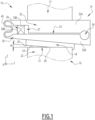
- Figure 1 shows a cutting device 10 according to a first embodiment of the invention.
- the cutting device 10 is intended to cut a coated electrode strip 12 in view of a manufacturing process of a battery.
- the second cutting tool 16 comprises a second blade 22 having a second cutting edge 24.
- the second cutting edge 24 forms a straight line.
- the means 30 for varying the angle comprise a support 32 for the first blade 18 that is partially tiltable.
- the support 32 comprises a first part 32A and a second part 32B, the first 32A and second 32B parts being connected by means of a hinge part 34, with a space 33 between the first 32A and second 32B parts.
- the first part 32A is connected to the displacement mean 17, and the second part 32B holds the first blade 18.
- the support 32 also comprises an actuator 36 between the first part 32A and the second part 32B, intended to drive the first 32A and second 32B parts in rotation around the hinge part 34.
- the actuator 36 is arranged in a housing 37 between the first 32A and second 32B parts.
- the actuator 36 is conformed to drive the first 32A and second 32B parts in an oscillating movement around the hinge part 34.
- the actuator 36 is, for example, a piezoelectric element.
- the actuator 36 extends vertically in the housing 37 between a first actuation point 38A of the first part 32A, and a second actuation point 38B of the second part 32B.
- the actuator 36 is driven by a power amplifier with alternating voltage at frequency, consequently, changing the distance between the actuation points 38A, 38B.
- the distance changes convert the second part 32B in a rotational motion with the hinge part 34 as the centre of rotation.
- the support 32 comprises spring bridges 40 between the first 32A and second 32B parts.
- the spring bridges 40 are arranged at a first end of the support 32 in the transversal direction Y, and the hinge part 34 is arranged at a second opposite end of the support 32 in the transversal direction Y.
- the spring bridges 40 are closing the housing 37 in the transversal direction Y.
- the support 32 comprises two parallel spring bridges 40.
- Each spring bridge 40 is for example bent three times, forming a W shape.
- the actuator 36 with the spring bridges 40 drive an oscillation movement of the second part 32B around the hinge part 34, thus an oscillation movement of the blade 18, modifying the cutting angle ⁇ at any time.
- the first blade 18 works in a superposed motion of a constant speed linear vertical motion (driven by the displacement mean 17) with an oscillating micro-motion (driven by the support 32) at significantly high speed. This is advantageous for producing clean-cut edges.
- the blades 18, 22 work like micro-scissors working with micro-strokes at significantly high-speed.
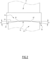
- a cutting device 10 according to a second embodiment is disclosed in reference to figure 2 .
- the elements analogous to the first embodiment are designed with the same reference numbers.
- the first blade 18 is directly held by the displacement mean 17.
- the first cutting edge 20 has a concave shape, wherein the first cutting edge 20 is symmetrical relating to a central transverse plane.
- the concave shape is elliptic.
- This concave shape provide a cutting sequence in such a way that the cutting starts at both lateral edges of the coated strip 12 almost simultaneously and the cutting ends in the middle of the coated strip 12.
- the two cutting points 26, 26' approach each other while cutting, to finally meet at a point (in the middle of the strip), ending the cutting.
- the cutting device 10 works with progressively varying cutting angles, starting with bigger angles and ending with a 0-degree cutting angle.
- the cutting quality at the lateral edges of the strip 12 is almost identical for both edges, which is different from the prior art.
- a cutting device 10 according to a third embodiment is disclosed in reference to figure 3 .
- the elements analogous to the first embodiment are designed with the same reference numbers.
- the cutting device 10 combines the advantages of the first and second embodiments.
- the means 30 for varying the angle comprises the support 32 holding the first blade 18 and the curved first cutting edge 20.
Landscapes
- Life Sciences & Earth Sciences (AREA)
- Forests & Forestry (AREA)
- Engineering & Computer Science (AREA)
- Mechanical Engineering (AREA)
- Nonmetal Cutting Devices (AREA)
Abstract
Description
- The present invention relates to a cutting device for cutting a coated electrode strip. Cutting a coated electrode strip takes place in a manufacturing process of a battery.
- A cutting device for cutting a coated electrode strip is already known from prior art. Such a cutting device usually comprises a stationary lower blade (also called "die") and a vertically moving upper blade (also called "punch"), the blades having cutting edges crossing each other with a specific shear angle. The lower and upper blades usually each have specific rake angle, independently from each other.
- The electrode strip is usually cut transversally, from a first lateral edge to a second opposite lateral edge.
- It should be noticed that making a clean-cut edge at the coated electrode strip is quite challenging as it is quite thin, and a sharp square corner with a burr tends to arise more frequently at the second edge side rather than at the first edge.
- However, in case the electrode does not have a clean-cut edge, it may cause a mild short-circuit between a cathode and an anode through a separator due to cutting burrs, which may lead to faster self-discharge of the battery cell, and which is a painful failure of the battery cell incurs high costs to correct.
- The invention is intended to solve this problem, by providing a cutting device enhancing the quality of the cut edge.
- To this end, the invention relates to a cutting device for cutting a coated electrode strip, comprising a first cutting tool having a first blade with a first cutting edge and a second cutting tool having a second blade with a second cutting edge, the first blade being movable relating to the second blade so that the first cutting edge and the second cutting edge are intended to cooperate on at least one movable cutting point, with a cutting angle defined between the first and second cutting edges at the cutting point, characterized in that the cutting device comprises means for varying the cutting angle at the cutting point while the first and second cutting tools move relating to each other.
- The means for varying the cutting angle allow a better quality of the cut edge than in case of a cut with a fixed cutting angle.
- Several means for varying the cutting angle will be disclosed in the disclosure. More particularly, a cutting device according to the invention may comprise any of the following features, taken alone or in any possible combination.
- The means for varying the angle comprise the first blade shaped so that the first cutting edge is curved.
- The first cutting edge has a concave shape, preferentially a shape that is symmetrical relating to a central transverse plane, for example an elliptic shape.
- The means for varying the angle comprise a support for the first blade that is able to tilt the first blade.
- The support comprises a first part and a second part, the second part holding the first blade, the first and second parts being connected by means of a hinge part.
- The support comprises an actuator arranged between the first part and the second part, intended to drive the second part in rotation around the hinge part.
- The actuator is conformed to drive the second part in an oscillating movement around the hinge part.
- The actuator is a piezoelectric element.
- The cutting device comprises at least one spring bridge extending between the first and second parts
- Several aspects and advantages of the invention will be enlightened in the following disclosure, only given as a non limitative example and made in reference to attached drawings in which:
-
Figure 1 is a front view of a cutting device according to a first embodiment of the invention; -
Figure 2 is a front view of a cutting device according to a second embodiment of the invention; -
Figure 3 is a perspective view of a cutting device according to a third embodiment of the invention. -
Figure 1 shows acutting device 10 according to a first embodiment of the invention. Thecutting device 10 is intended to cut a coatedelectrode strip 12 in view of a manufacturing process of a battery. - The
cutting device 10 comprise afirst cutting tool 14 and asecond cutting tool 16. - The
second cutting tool 16 is fixed, forming a die, and thefirst cutting tool 14 forms a punch at least partially movable in a vertical direction Z towards thesecond cutting tool 16. To this end, thefirst cutting tool 14 comprises a classical displacement mean 17 for displacing thefirst cutting tool 14 in the vertical direction Z. - The
first cutting tool 14 comprises afirst blade 18 having afirst cutting edge 20. In the first embodiment, thefirst cutting edge 20 forms a straight line. - The
second cutting tool 16 comprises asecond blade 22 having a secondcutting edge 24. In the first embodiment, the secondcutting edge 24 forms a straight line. - The first
cutting edge 20 and thesecond cutting edge 24 are intended to cooperate on at least onemovable cutting point 26, that is the point where the coatedelectrode strip 12 is cut. Thecutting point 26 is an abstract point, that moves transversally along the coatedelectrode strip 12 in a transversal direction Y perpendicular to the vertical direction, while thefirst blade 18 moves towards thesecond blade 22 in the vertical direction Z. - The
cutting point 26 is formed because thefirst cutting edge 20 is tilted by respect to thesecond cutting edge 24, with an angle α. - We define a cutting angle that is the angle between the
first cutting edge 20 and thesecond cutting edge 24 at thecutting point 26. Because thefirst cutting edge 20 and thesecond cutting edge 24 are straight lines, the cutting angle is the same as the angle α. - It appears that a cut is cleaner when the cutting angle varies during the cut. Thus, the invention provides a cutting device comprising means 30 for varying the cutting angle at the
cutting point 26 while the first 14 and second 16 cutting tools move relating to each other. - In conformity with the first embodiment, the
means 30 for varying the angle comprise asupport 32 for thefirst blade 18 that is partially tiltable. - The
support 32 comprises afirst part 32A and asecond part 32B, the first 32A and second 32B parts being connected by means of ahinge part 34, with aspace 33 between the first 32A and second 32B parts. - The
hinge part 34 is for example formed by a through hole in the longitudinal direction X perpendicular to the vertical direction Z and to the transversal direction Y. - The
first part 32A is connected to the displacement mean 17, and thesecond part 32B holds thefirst blade 18. - The
support 32 also comprises anactuator 36 between thefirst part 32A and thesecond part 32B, intended to drive the first 32A and second 32B parts in rotation around thehinge part 34. Theactuator 36 is arranged in ahousing 37 between the first 32A and second 32B parts. - Preferentially, the
actuator 36 is conformed to drive the first 32A and second 32B parts in an oscillating movement around thehinge part 34. - The
actuator 36 is, for example, a piezoelectric element. Theactuator 36 extends vertically in thehousing 37 between afirst actuation point 38A of thefirst part 32A, and asecond actuation point 38B of thesecond part 32B. - The
actuator 36 is driven by a power amplifier with alternating voltage at frequency, consequently, changing the distance between theactuation points - The distance changes convert the
second part 32B in a rotational motion with thehinge part 34 as the centre of rotation. - Preferentially, the
support 32 comprisesspring bridges 40 between the first 32A and second 32B parts. Thespring bridges 40 are arranged at a first end of thesupport 32 in the transversal direction Y, and thehinge part 34 is arranged at a second opposite end of thesupport 32 in the transversal direction Y. Thespring bridges 40 are closing thehousing 37 in the transversal direction Y. - For example, the
support 32 comprises twoparallel spring bridges 40. - Each
spring bridge 40 is for example bent three times, forming a W shape. - The
actuator 36 with thespring bridges 40 drive an oscillation movement of thesecond part 32B around thehinge part 34, thus an oscillation movement of theblade 18, modifying the cutting angle α at any time. - In the cutting device of the first embodiment, the
first blade 18 works in a superposed motion of a constant speed linear vertical motion (driven by the displacement mean 17) with an oscillating micro-motion (driven by the support 32) at significantly high speed. This is advantageous for producing clean-cut edges. In other words, theblades - A
cutting device 10 according to a second embodiment is disclosed in reference tofigure 2 . On this figure, the elements analogous to the first embodiment are designed with the same reference numbers. - In this second embodiment, the
first blade 18 is directly held by the displacement mean 17. - The
means 30 for varying the angle comprise thefirst blade 18, with the firstcutting edge 20 being curved. - Because of the curved shape, the cutting angle, defined between a tangent to the curved
first cutting edge 20 and thesecond cutting edge 24, varies when thefirst blade 18 is vertically displaced. - Preferentially, the
first cutting edge 20 has a concave shape, wherein thefirst cutting edge 20 is symmetrical relating to a central transverse plane. For example, the concave shape is elliptic. - Such a concave shape crosses the
second cutting edge 24 on twocutting points 26, 26'. We thus define two cutting angles α, α' that are opposite. - This concave shape provide a cutting sequence in such a way that the cutting starts at both lateral edges of the
coated strip 12 almost simultaneously and the cutting ends in the middle of thecoated strip 12. In other words, the twocutting points 26, 26' approach each other while cutting, to finally meet at a point (in the middle of the strip), ending the cutting. - With this arrangement, the cutting
device 10 works with progressively varying cutting angles, starting with bigger angles and ending with a 0-degree cutting angle. The cutting quality at the lateral edges of thestrip 12 is almost identical for both edges, which is different from the prior art. - A cutting
device 10 according to a third embodiment is disclosed in reference tofigure 3 . On this figure, the elements analogous to the first embodiment are designed with the same reference numbers. - The cutting
device 10 according to the third embodiment combines the advantages of the first and second embodiments. In other words, themeans 30 for varying the angle comprises thesupport 32 holding thefirst blade 18 and the curvedfirst cutting edge 20. - The advantages are the same as in the first and second embodiments, so they will not be disclosed again.
Claims (9)
- A cutting device (10) for cutting a coated electrode strip (12), comprising a first cutting tool (14) having a first blade (18) with a first cutting edge (20) and a second cutting tool (16) having a second blade (22) with a second cutting edge (24), the first blade (18) being movable relating to the second blade (22) so that the first cutting edge (20) and the second cutting edge (24) are intended to cooperate on at least one movable cutting point (26), with a cutting angle (α) defined between the first (20) and second (24) cutting edges at the cutting point (26), characterized in that the cutting device (10) comprises means (30) for varying the cutting angle (α) at the cutting point (26) while the first (14) and second (16) cutting tools move relating to each other.
- The cutting device (10) according to claim 1, wherein the means (30) for varying the angle comprise the first blade (18) shaped so that the first cutting edge (20) is curved.
- The cutting device (10) according to claim 2, wherein the first cutting edge (20) has a concave shape, preferentially a shape that is symmetrical relating to a central transverse plane, for example an elliptic shape.
- The cutting device (10) according to any of preceding claims, wherein the means (30) for varying the angle comprise a support (32) for the first blade (18) that is able to tilt the first blade (18).
- The cutting device (10) according to claim 4, wherein the support (32) comprises a first part (32A) and a second part (32B), the second part (32B) holding the first blade (18), the first (32A) and second (32B) parts being connected by means of a hinge part (34).
- The cutting device (10) according to claim 5, wherein the support (32) comprises an actuator (36) arranged between the first part (32A) and the second part (32B), intended to drive the second part (32B) in rotation around the hinge part (34).
- The cutting device (10) according to claim 6, wherein the actuator (36) is conformed to drive the second part (32B) in an oscillating movement around the hinge part (34).
- The cutting device (10) according to claim 7, wherein the actuator (36) is a piezoelectric element.
- The cutting device (10) according to any of claims 5 to 8, comprising at least one spring bridge (40) extending between the first (32A) and second (32B) parts
Priority Applications (1)
| Application Number | Priority Date | Filing Date | Title |
|---|---|---|---|
| EP23307358.4A EP4574358A1 (en) | 2023-12-22 | 2023-12-22 | Cutting device for cutting a coated electrode strip |
Applications Claiming Priority (1)
| Application Number | Priority Date | Filing Date | Title |
|---|---|---|---|
| EP23307358.4A EP4574358A1 (en) | 2023-12-22 | 2023-12-22 | Cutting device for cutting a coated electrode strip |
Publications (1)
| Publication Number | Publication Date |
|---|---|
| EP4574358A1 true EP4574358A1 (en) | 2025-06-25 |
Family
ID=89619710
Family Applications (1)
| Application Number | Title | Priority Date | Filing Date |
|---|---|---|---|
| EP23307358.4A Pending EP4574358A1 (en) | 2023-12-22 | 2023-12-22 | Cutting device for cutting a coated electrode strip |
Country Status (1)
| Country | Link |
|---|---|
| EP (1) | EP4574358A1 (en) |
Citations (2)
| Publication number | Priority date | Publication date | Assignee | Title |
|---|---|---|---|---|
| US20080314217A1 (en) * | 2005-03-10 | 2008-12-25 | Etablissements Pierre Grehal Et Cie Sa | Cutting Tool For Cutting a Plate |
| KR102040777B1 (en) * | 2019-06-11 | 2019-11-06 | 주식회사 우원기술 | Electrode Cutter for Secondary Battery |
-
2023
- 2023-12-22 EP EP23307358.4A patent/EP4574358A1/en active Pending
Patent Citations (2)
| Publication number | Priority date | Publication date | Assignee | Title |
|---|---|---|---|---|
| US20080314217A1 (en) * | 2005-03-10 | 2008-12-25 | Etablissements Pierre Grehal Et Cie Sa | Cutting Tool For Cutting a Plate |
| KR102040777B1 (en) * | 2019-06-11 | 2019-11-06 | 주식회사 우원기술 | Electrode Cutter for Secondary Battery |
Similar Documents
| Publication | Publication Date | Title |
|---|---|---|
| EP3585574B1 (en) | Electric handheld hair trimmer with blade guard | |
| US5802932A (en) | Cutter for a cutting device of an electric shaving apparatus or beard trimmer | |
| US6973855B2 (en) | Method for manufacturing hair clipper blade | |
| US20100095531A1 (en) | Method of manufacturing a cutting member of a shaver | |
| KR20120027238A (en) | Razor cartridge and mechanical razor comprising such a cartridge | |
| CN110091364A (en) | A kind of hair cuts the processing technology of utensil, cutter unit, quiet knife structure and quiet knife structure | |
| JP2025505552A (en) | Dresser and method for dressing projection welding electrodes having a double helix structure | |
| CN102143829A (en) | Cutting head for a razor | |
| MXPA05000581A (en) | Method of manufacturing cutter of reciprocating type electric razor and cutter. | |
| JPH06270006A (en) | Working of arcuate root groove of turbine moving blade | |
| US20170355088A1 (en) | Cutting head for electric hair clippers | |
| KR101464491B1 (en) | Method and device for trimming heavy plates | |
| WO2010038618A1 (en) | Electric shaver | |
| CN115319215B (en) | Non-perforated wire cutting process | |
| JP5915767B2 (en) | Cutting device and cutting method | |
| JP2008510500A (en) | Sharp undercutter and undercutter production | |
| CN114473004B (en) | Waste cutting machine | |
| JP4479988B2 (en) | Electric razor | |
| EP1568450A1 (en) | Reciprocating electric shaver, inner cutter and inner cutter manufacturing method | |
| CN115533973A (en) | A kind of processing method of composite material thin plate and composite material thin plate | |
| CN211615689U (en) | Shaving device | |
| EP1454720A1 (en) | A reciprocating type electric shaver | |
| CN112549090B (en) | Reciprocating electric razor | |
| CN211218252U (en) | Air conditioner fin rip cutting cutter | |
| CN103192421A (en) | Cutting machine with variation of the cutting area |
Legal Events
| Date | Code | Title | Description |
|---|---|---|---|
| PUAI | Public reference made under article 153(3) epc to a published international application that has entered the european phase |
Free format text: ORIGINAL CODE: 0009012 |
|
| STAA | Information on the status of an ep patent application or granted ep patent |
Free format text: STATUS: THE APPLICATION HAS BEEN PUBLISHED |
|
| AK | Designated contracting states |
Kind code of ref document: A1 Designated state(s): AL AT BE BG CH CY CZ DE DK EE ES FI FR GB GR HR HU IE IS IT LI LT LU LV MC ME MK MT NL NO PL PT RO RS SE SI SK SM TR |
|
| P01 | Opt-out of the competence of the unified patent court (upc) registered |
Free format text: CASE NUMBER: UPC_APP_2705_4574358/2025 Effective date: 20250807 |
|
| STAA | Information on the status of an ep patent application or granted ep patent |
Free format text: STATUS: REQUEST FOR EXAMINATION WAS MADE |
|
| 17P | Request for examination filed |
Effective date: 20251127 |