EP4574344A1 - Table saw with rise stand - Google Patents
Table saw with rise stand Download PDFInfo
- Publication number
- EP4574344A1 EP4574344A1 EP24217196.5A EP24217196A EP4574344A1 EP 4574344 A1 EP4574344 A1 EP 4574344A1 EP 24217196 A EP24217196 A EP 24217196A EP 4574344 A1 EP4574344 A1 EP 4574344A1
- Authority
- EP
- European Patent Office
- Prior art keywords
- stand
- support member
- table saw
- assembly
- pivot
- Prior art date
- Legal status (The legal status is an assumption and is not a legal conclusion. Google has not performed a legal analysis and makes no representation as to the accuracy of the status listed.)
- Pending
Links
Images

Classifications
-
- B—PERFORMING OPERATIONS; TRANSPORTING
- B23—MACHINE TOOLS; METAL-WORKING NOT OTHERWISE PROVIDED FOR
- B23D—PLANING; SLOTTING; SHEARING; BROACHING; SAWING; FILING; SCRAPING; LIKE OPERATIONS FOR WORKING METAL BY REMOVING MATERIAL, NOT OTHERWISE PROVIDED FOR
- B23D47/00—Sawing machines or sawing devices working with circular saw blades, characterised only by constructional features of particular parts
- B23D47/02—Sawing machines or sawing devices working with circular saw blades, characterised only by constructional features of particular parts of frames; of guiding arrangements for work-table or saw-carrier
-
- B—PERFORMING OPERATIONS; TRANSPORTING
- B23—MACHINE TOOLS; METAL-WORKING NOT OTHERWISE PROVIDED FOR
- B23D—PLANING; SLOTTING; SHEARING; BROACHING; SAWING; FILING; SCRAPING; LIKE OPERATIONS FOR WORKING METAL BY REMOVING MATERIAL, NOT OTHERWISE PROVIDED FOR
- B23D47/00—Sawing machines or sawing devices working with circular saw blades, characterised only by constructional features of particular parts
- B23D47/02—Sawing machines or sawing devices working with circular saw blades, characterised only by constructional features of particular parts of frames; of guiding arrangements for work-table or saw-carrier
- B23D47/025—Sawing machines or sawing devices working with circular saw blades, characterised only by constructional features of particular parts of frames; of guiding arrangements for work-table or saw-carrier of tables
-
- B—PERFORMING OPERATIONS; TRANSPORTING
- B27—WORKING OR PRESERVING WOOD OR SIMILAR MATERIAL; NAILING OR STAPLING MACHINES IN GENERAL
- B27B—SAWS FOR WOOD OR SIMILAR MATERIAL; COMPONENTS OR ACCESSORIES THEREFOR
- B27B5/00—Sawing machines working with circular or cylindrical saw blades; Components or equipment therefor
- B27B5/16—Saw benches
-
- B—PERFORMING OPERATIONS; TRANSPORTING
- B25—HAND TOOLS; PORTABLE POWER-DRIVEN TOOLS; MANIPULATORS
- B25H—WORKSHOP EQUIPMENT, e.g. FOR MARKING-OUT WORK; STORAGE MEANS FOR WORKSHOPS
- B25H1/00—Work benches; Portable stands or supports for positioning portable tools or work to be operated on thereby
- B25H1/02—Work benches; Portable stands or supports for positioning portable tools or work to be operated on thereby of table type
- B25H1/04—Work benches; Portable stands or supports for positioning portable tools or work to be operated on thereby of table type portable
-
- B—PERFORMING OPERATIONS; TRANSPORTING
- B27—WORKING OR PRESERVING WOOD OR SIMILAR MATERIAL; NAILING OR STAPLING MACHINES IN GENERAL
- B27B—SAWS FOR WOOD OR SIMILAR MATERIAL; COMPONENTS OR ACCESSORIES THEREFOR
- B27B5/00—Sawing machines working with circular or cylindrical saw blades; Components or equipment therefor
- B27B5/29—Details; Component parts; Accessories
Definitions
- the present disclosure relates to power tools and more particularly to stands for power tools such as table saws.
- Rolling hand trucks or support stands for large and/or heavy objects are known and are useful for transporting such objects from one location to another. Some of such known support stands are collapsible to some degree and many different designs of the hand trucks or rolling support stands are particularly suited for specific uses. While such products may be used in many different industries and applications, one noteworthy use is that of transporting objects, such as portable table saws, miter saws and the like to and from construction sites.
- carpenters In the home building trade, carpenters generally have table saws as well as other types of saws that are brought to a jobsite every day in the tradesman's truck or are stored in a secure location at the jobsite and must be removed from the truck or stored location and be set up on the jobsite while work is being done. At the end of the work day, the tradesman must pack up the saw and return it to his truck or secure location for safe keeping. Because such tools are valuable, they cannot be left unattended overnight without a significant risk of theft.
- stands may unfold using a spring biasing mechanism that is released and which then supplies a major force tending to place the stand with the saw attached to it in its proper working generally horizontal position.
- stands of this type may be dangerous if the folded stand has the mechanism released when the weight of the saw is not over the stand mechanism. If there is no load on the mechanism, it can unfold very rapidly which can be quite dangerous if a tradesman or any other person is struck by the mechanism.
- some configurations of the spring biasing mechanism force a user into an unbalanced stance when operating the spring biasing mechanism. This can lead to accidents.
- Stands which are used with power tools such as table saws are frequently provided with support feet consisting of wing nuts, threaded rods, and metal feet surrounded by small rubber bumpers. These bumpers, however, are prone to falling off when the stand is being used or transported which leaves an exposed metal foot. Subsequent use of the stand can result in damage to finished floors on the jobsite. The metal foot is also prone to rusting and deformation because of the environmental factors of working on a job site
- a stand which is ergonomically easy to use would be beneficial. It would be further beneficial if the stand included support structures which reduced the potential for damage to underlying support structures. A stand which is robustly configured for a construction environment is further desirable.
- the present disclosure is directed to a system including a stand for a power tool such as a table saw.
- the stand includes strategically placed pivot points which utilize the weight of the saw to cause the stand to automatically move to an intermediate position from which a user can easily move the stand into an open position or a closed position.
- the power tool system is a table saw system including a table saw and a stand configured to support the table saw.
- the stand includes a table saw coupling assembly configured to couple with the table saw.
- An intermediate support member is pivotably coupled to the table saw coupling assembly through at least one first pivot.
- a lower support member is pivotably coupled to the intermediate support member through at least one second pivot.
- a longitudinal support member is pivotably connected to the table saw coupling assembly through at least one third pivot, and pivotably connected to the lower support member through at least one fourth pivot, Typically, two pivots are provided for each of the pivots above.
- the pivots are provided in a number of different forms in different embodiments. In some instances, the pivotably connected components are both movable with respect to the pivot.
- the pivots fixedly connected to one of the components.
- the stand is configured to be movable between a closed upright position whereat the table saw is generally vertically oriented, an open position whereat the table saw is generally horizontally oriented, and an intermediate position from which the stand is alternatively movable to either of the closed upright position and the open position without passing through the other of the closed position and the open position.
- the table saw is generally vertically oriented in the intermediate position.
- the second pivot is closer to a vertical plane in which a pivot axis of the fourth pivot extends when the stand is in the intermediate position than when the stand is in the closed upright position.
- the stand is configured to move from the closed upright position to the intermediate position automatically when the table saw is coupled to the table saw coupling assembly.
- only the stand is provided.
- the stand is configured such that when the stand is in the closed upright position a minimum distance between the at least one second pivot and a vertical plane extending through the fourth pivot is > 0.25 inches and ⁇ 3 inches.
- a minimum distance between a horizontal plane extending through the at least one second pivot and a horizontal plane extending through the at least one fourth pivot is ⁇ 1 inch and ⁇ 6 inches.
- the stand includes a tube stop assembly mounted on one of the lower support member, the intermediate support member, and the table saw coupling assembly.
- the tube stop assembly is configured to abut the other two of the lower support member, the intermediate support member, and the table saw coupling assembly when the stand is in a closed horizontal position to provide support and when the stand is in the closed position.
- the tube stop assembly includes a stop bolt configured to contact one of the intermediate support member and the table saw coupling assembly when the stand is in the closed horizontal position.
- the stop bolt provides precise positioning of the components.
- the intermediate support member has a first end portion and a second end portion opposite the first end portion.
- a locking pin is located at the second end portion of the intermediate support member.
- a locking latch is slidably connected to the lower support member and a foot actuator is pivotably connected to the lower support member and the locking latch.
- the locking pin and locking latch are configured to automatically lock the stand when the stand is moved to the open position.
- the foot actuator is configured to unlock the locking pin and locking latch when the foot actuator is moved from a first position to a second position. Additionally, the locking pin is configured to contact the lower support member in the open position.
- the stand includes a protective plate mounted on the longitudinal support.
- the protective plate is configured such that when the stand is in a closed horizontal position a lower edge of the protective plate extends farther downwardly than a lowermost portion of the locking latch.
- the lower edge is preferably rounded to provide a sliding surface in case of contact between the stand and an underlying object as the stand is moved.
- wheels are rotatably connected to the lower support member.
- the wheels may be connected to the lower support member in any desired manner.
- the stand includes a vertical stabilizer extending from the longitudinal support.
- the vertical stabilizer is configured to maintain the stand in a vertical condition when the stand is in the closed upright position and the intermediate position.
- the lower support member includes a lower leg and an upper leg.
- the second and fourth pivots are partially located within or coupled to the upper leg.
- the intermediate support member includes an upper arm and a lower arm. The first and second pivots are partially located within or coupled to the upper arm.
- the upper arm extends at a non-zero angle from the lower arm in a direction toward the table saw coupling assembly.
- a latching assembly is provided with the stand.
- the latching assembly is movable between a locking position at which the stand automatically locks when the stand is moved into the open position and/or when the stand is moved into the closed upright position.
- the stand is configured to move from the closed upright position to the intermediate position automatically when the table saw is coupled to the table saw coupling assembly and the latching assembly is moved from the locking position to the unlocked position.
- the intermediate support member has a first end portion and a second end portion opposite the first end portion.
- the latching assembly includes a locking pin at the second end portion of the intermediate support member.
- a locking latch is slidably connected to the lower support member.
- a foot actuator pivotably connected to the lower support member and the locking latch.
- a method of operating a stand and/or a power tool system including the stand includes unlocking a latching element when the stand is in an upright closed position.
- the stand is configured such that upon being unlocking, the stand automatically moves to an intermediate position. From the intermediate position, the stand can be moved to either an open position or to the closed upright position.
- FIG. 8 which shows the table saw assembly 100 with the table saw 102 removed for clarity
- the stand 104 is in a closed horizontal position. In the closed horizontal position, the table saw assembly 100 is supported on a surface with the wheels 152/154 and the W-shaped handle 118.
- the coupling assembly 106 is supported in the closed horizontal position by the tube stops 134/136.
- the tube stops are similarly configured and are described in more detail with reference to tube stop 136 as shown in FIGs. 2 and 9 .
- a user grasps the W-shaped handle 118. Because of the design of the W-shaped handle 118, when the stand is in the closed horizontal position, the W-shaped handle 118 provides an elevated portion 204 (see FIG. 8 ). Consequently, a user does not need to reach down as far to grab the W-shaped handle 118.
- the W-shaped handle is then used to pivot the stand 104 about the wheels 152/154 so that the table saw assembly 100 can be maneuvered using the wheels 152/154.
- the latching assembly 210 includes a foot pedal 212 which is rigidly connected to a connecting plate 214 such that pivoting of the foot pedal 212 causes pivoting of the connecting plate 214.
- the foot pedal 212 and connecting plate 214 are pivotably connected to the lower support member 142 through a pivot 216.
- the foot pedal 212 and connecting plate 214 are biased to place the latching assembly 210 in a locking position shown in FIG. 10 by a spring 215 (see FIG. 6 ) or other biasing member between the foot pedal 212 and connecting plate 214 and the lower support member 142.
- the biasing force acts in a counterclockwise direction about the pivot 216 in the view shown in FIG. 10 .
- Mounting of the foot pedal 212 within the footprint of the wheel support member 150 protects the foot pedal 212 from accidental activation.
- the vertical stabilizer 120 In the closed upright position of FIG. 12 , the vertical stabilizer 120, along with the wheels 152/154, maintains the table saw assembly 100 in a stable vertical position so long as the locking pin 236 is maintained within the groove 230 of the latch 218.
- the wheel axles (see, e.g., wheel axle 244 of wheel 152) are located to the left of a vertical plane 250 in which a pivot axis 252 of the pivots 146 and 148 extends.
- the pivots 164 and 166 are also located to the left of the vertical plane 250.
- the table saw 102 (not shown in FIG. 12 ) is located to the right of the vertical plane 250 in a substbatially vertical position.
- the weight of the table saw 102 acting through the pivots 146/148 and the axle(s) 244 provides a force tending to push the wheels 152/154 in a leftwardly direction.
- the latching assembly 210 prevents this movement.
- the user When the user desires to move the table saw assembly into an open position, the user depresses the foot pedal 212 (see FIGs. 6 and 10 ) which acts against the biasing force of the spring 215 causing the connecting plate 214 to rotate in a clockwise direction (in the view of FIG. 10 ). Pivoting of the connecting plate 214 causes the latch 218 to move downwardly guided by the screw 234 within the slot 232 until the locking pin 236 is no longer within the receiving groove 230.
- the longitudinal support members 110/112 rotate leftwardly and contact with the underlying support surface shifts from the support pads 122/124 to the anti-tip feet 126/128.
- the support pads 122/124 and the anti-tip feet 126/128 are configured to simultaneously be in contact with the underlying support surface.
- contact moves from the support pads 122/124 to the connections between the vertical stabilizer 120 and the longitudinal support members 110/112.
- the wheels 152/154 continue to move away from the vertical plane 250 throughout the change in contact from the support pads 122/124 to the anti-tip feet 126/128.
- the locking pin 180 comes into contact with the activation surface 226 of the latch 218. This contact presses the latch 218 downwardly causing the connecting plate 214 to rotate against the biasing force of the spring 215. This movement continues until the locking pin 180 moves into the groove 230 at which time the spring 215 causes the connecting plate 214 (and foot pedal 212) to rotate in a counter-clockwise direction (in the view of FIG. 10 ). Counter-clockwise pivoting of the connecting plate 214 causes the latch 218 to move upwardly guided by the screw 234 within the slot 232 thereby locking the locking pin 180 within the receiving groove 230.
- the locking pins 180/182 also move into contact with the lower support members 140/142. Further movement away from the intermediate position of FIG. 13 is thereby terminated and the table saw assembly 100 is in the open position of FIG. 2 with the table saw in a substantially horizontal configuration. Accordingly, the table saw 102 is in position for use. The user may then use the table saw 102 as desired.
- the user pivots the foot pedal 212 in a clockwise direction (as viewed in FIG. 10 ) by overcoming the biasing force of the spring 215.
- the clockwise pivoting of the foot pedal 212 causes the connecting plate 214 to pivot in a clockwise direction about the pivot 216 thereby forcing the latch 218 downwardly.
- the locking pin 180 is no longer constrained within the groove 230. The user then lifts upwardly with the W-shaped handle 118.
- the locking pin 236 which is fixedly connected to the longitudinal support member 110 contacts the activation surface 228 of the latch 218. This forces the latch 218 downwardly causing the connecting plate 214 to rotate against the biasing force of the spring 215. This movement continues until the locking pin 236 moves into the groove 230 at which time the spring 215 causes the connecting plate 214 (and foot pedal 212) to rotate in a counter-clockwise direction (in the view of FIG. 10 ). Counter-clockwise pivoting of the connecting plate 214 causes the latch 218 to move upwardly guided by the screw 234 within the slot 232 thereby locking the locking pin 236.
- the tube stops 134/136 move into contact with the coupling assembly 106 and the lower support member 150 (see FIG. 9 ). Further movement away from the intermediate position of FIG. 13 is thereby terminated and the table saw assembly 100 is in the closed upright position of FIG. 12 with the table saw in a substantially vertical configuration. Accordingly, the table saw assembly 100 can be safely moved as desired.
Landscapes
- Engineering & Computer Science (AREA)
- Mechanical Engineering (AREA)
- Life Sciences & Earth Sciences (AREA)
- Wood Science & Technology (AREA)
- Forests & Forestry (AREA)
- Sawing (AREA)
- Workshop Equipment, Work Benches, Supports, Or Storage Means (AREA)
Abstract
A table saw system (100) includes a table saw (102), and a stand (104) including a table saw coupling assembly (106), an intermediate support (168, 170) pivotably coupled to the coupling assembly (106), and a lower support (142, 144) pivotably coupled to the intermediate support through a second pivot. A longitudinal support (110, 112) pivotably connects to the coupling assembly (106) through a third pivot, and pivotably connects to the lower support through a fourth pivot. The stand is alternatively movable from an intermediate position to a closed position whereat the table saw (102) is vertically oriented, or an open position, whereat the table saw (102) is horizontally oriented, without passing through the other of the closed and open position. The table saw (102) is vertically oriented in the intermediate position with the second pivot closer to a vertical plane extending through the fourth pivot than when the stand is in the closed position. Movement from the closed position to the intermediate position is automatic.
Description
- The present disclosure relates to power tools and more particularly to stands for power tools such as table saws.
- Rolling hand trucks or support stands for large and/or heavy objects are known and are useful for transporting such objects from one location to another. Some of such known support stands are collapsible to some degree and many different designs of the hand trucks or rolling support stands are particularly suited for specific uses. While such products may be used in many different industries and applications, one noteworthy use is that of transporting objects, such as portable table saws, miter saws and the like to and from construction sites.
- In the home building trade, carpenters generally have table saws as well as other types of saws that are brought to a jobsite every day in the tradesman's truck or are stored in a secure location at the jobsite and must be removed from the truck or stored location and be set up on the jobsite while work is being done. At the end of the work day, the tradesman must pack up the saw and return it to his truck or secure location for safe keeping. Because such tools are valuable, they cannot be left unattended overnight without a significant risk of theft.
- There is also an issue of setting up the saw at the worksite. Even though early prior art roll stands or hand trucks may help the tradesman to move the saw to the desired location, it was often necessary to have a table or other surface, such as wooden planks resting on saw horses or the like to bring the saw to a convenient working height during use. Although more recent designs have evolved which have a rolling stand that can be unfolded to support the saw at an appropriate working height, many designs that double as a stand require the tradesman to lift a substantial portion of the weight of the saw which is typically relatively heavy.
- Many portable table saws are very similar in design to standard table saws except they do not have a stand with legs beneath them and must be supported by a separate structure. Such portable table saws are rugged commercial tools that are built for an extended useful life and are therefore relatively heavy. Typical table saws of this type may weigh 60 pounds or more. While most tradesmen can usually lift 40-60 pounds, such exertion is inconvenient and perhaps dangerous in certain circumstances.
- Other types of stands may unfold using a spring biasing mechanism that is released and which then supplies a major force tending to place the stand with the saw attached to it in its proper working generally horizontal position. However, stands of this type may be dangerous if the folded stand has the mechanism released when the weight of the saw is not over the stand mechanism. If there is no load on the mechanism, it can unfold very rapidly which can be quite dangerous if a tradesman or any other person is struck by the mechanism. Moreover, some configurations of the spring biasing mechanism force a user into an unbalanced stance when operating the spring biasing mechanism. This can lead to accidents.
- Stands which are used with power tools such as table saws are frequently provided with support feet consisting of wing nuts, threaded rods, and metal feet surrounded by small rubber bumpers. These bumpers, however, are prone to falling off when the stand is being used or transported which leaves an exposed metal foot. Subsequent use of the stand can result in damage to finished floors on the jobsite. The metal foot is also prone to rusting and deformation because of the environmental factors of working on a job site
- A stand which is ergonomically easy to use would be beneficial. It would be further beneficial if the stand included support structures which reduced the potential for damage to underlying support structures. A stand which is robustly configured for a construction environment is further desirable.
- The present disclosure is directed to a system including a stand for a power tool such as a table saw. The stand includes strategically placed pivot points which utilize the weight of the saw to cause the stand to automatically move to an intermediate position from which a user can easily move the stand into an open position or a closed position.
- In one embodiment, the power tool system is a table saw system including a table saw and a stand configured to support the table saw. The stand includes a table saw coupling assembly configured to couple with the table saw. An intermediate support member is pivotably coupled to the table saw coupling assembly through at least one first pivot. A lower support member is pivotably coupled to the intermediate support member through at least one second pivot. A longitudinal support member is pivotably connected to the table saw coupling assembly through at least one third pivot, and pivotably connected to the lower support member through at least one fourth pivot, Typically, two pivots are provided for each of the pivots above. The pivots are provided in a number of different forms in different embodiments. In some instances, the pivotably connected components are both movable with respect to the pivot. In some instances, the pivots fixedly connected to one of the components. The stand is configured to be movable between a closed upright position whereat the table saw is generally vertically oriented, an open position whereat the table saw is generally horizontally oriented, and an intermediate position from which the stand is alternatively movable to either of the closed upright position and the open position without passing through the other of the closed position and the open position. The table saw is generally vertically oriented in the intermediate position. The second pivot is closer to a vertical plane in which a pivot axis of the fourth pivot extends when the stand is in the intermediate position than when the stand is in the closed upright position. The stand is configured to move from the closed upright position to the intermediate position automatically when the table saw is coupled to the table saw coupling assembly.
- In some embodiments, only the stand is provided.
- In one or more embodiments, the stand is configured such that when the stand is in the closed upright position a minimum distance between the at least one second pivot and a vertical plane extending through the fourth pivot is > 0.25 inches and ≤ 3 inches.
- In one or more embodiments, a minimum distance between a horizontal plane extending through the at least one second pivot and a horizontal plane extending through the at least one fourth pivot is ≥ 1 inch and ≤ 6 inches.
- In some embodiments the stand includes a tube stop assembly mounted on one of the lower support member, the intermediate support member, and the table saw coupling assembly. The tube stop assembly is configured to abut the other two of the lower support member, the intermediate support member, and the table saw coupling assembly when the stand is in a closed horizontal position to provide support and when the stand is in the closed position.
- In one or more embodiments, the tube stop assembly includes a stop bolt configured to contact one of the intermediate support member and the table saw coupling assembly when the stand is in the closed horizontal position. The stop bolt provides precise positioning of the components.
- In one or more embodiments, the intermediate support member has a first end portion and a second end portion opposite the first end portion. A locking pin is located at the second end portion of the intermediate support member. A locking latch is slidably connected to the lower support member and a foot actuator is pivotably connected to the lower support member and the locking latch. The locking pin and locking latch are configured to automatically lock the stand when the stand is moved to the open position. The foot actuator is configured to unlock the locking pin and locking latch when the foot actuator is moved from a first position to a second position. Additionally, the locking pin is configured to contact the lower support member in the open position.
- In one or more embodiments, the stand includes a protective plate mounted on the longitudinal support. The protective plate is configured such that when the stand is in a closed horizontal position a lower edge of the protective plate extends farther downwardly than a lowermost portion of the locking latch. The lower edge is preferably rounded to provide a sliding surface in case of contact between the stand and an underlying object as the stand is moved.
- In one or more embodiments, wheels are rotatably connected to the lower support member. The wheels may be connected to the lower support member in any desired manner.
- In one or more embodiments, the stand includes a vertical stabilizer extending from the longitudinal support. The vertical stabilizer is configured to maintain the stand in a vertical condition when the stand is in the closed upright position and the intermediate position.
- In one or more embodiments, the lower support member includes a lower leg and an upper leg. The second and fourth pivots are partially located within or coupled to the upper leg. When the stand is in the open position, the upper leg extends at a non-zero angle from the lower leg in a direction toward the table saw coupling assembly. The intermediate support member includes an upper arm and a lower arm. The first and second pivots are partially located within or coupled to the upper arm. When the stand is in the open position, the upper arm extends at a non-zero angle from the lower arm in a direction toward the table saw coupling assembly.
- In one or more embodiments, a latching assembly is provided with the stand. The latching assembly is movable between a locking position at which the stand automatically locks when the stand is moved into the open position and/or when the stand is moved into the closed upright position. The stand is configured to move from the closed upright position to the intermediate position automatically when the table saw is coupled to the table saw coupling assembly and the latching assembly is moved from the locking position to the unlocked position.
- In one or more embodiments the intermediate support member has a first end portion and a second end portion opposite the first end portion. The latching assembly includes a locking pin at the second end portion of the intermediate support member. A locking latch is slidably connected to the lower support member. A foot actuator pivotably connected to the lower support member and the locking latch.
- In one or more embodiments, a method of operating a stand and/or a power tool system including the stand includes unlocking a latching element when the stand is in an upright closed position. The stand is configured such that upon being unlocking, the stand automatically moves to an intermediate position. From the intermediate position, the stand can be moved to either an open position or to the closed upright position.
-
-
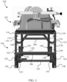
FIG. 1 shows a front plan view of a table saw assembly with the table saw in a horizontal position and the stand in an open horizontal configuration. -
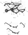
FIG. 2 shows a side perspective view of the table saw assembly ofFIG. 1 with the table saw removed for clarity. -
FIG. 3 shows an exploded view of the longitudinal support members and the vertical stabilizer of the table saw assembly ofFIG. 1 . -
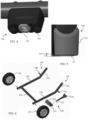
FIG. 4 shows a bottom perspective view of an anti-tip foot of the table saw assembly ofFIG. 1 . -
FIG. 5 shows a rear plan view of an anti-tip foot of the table saw assembly ofFIG. 1 . -
FIG. 6 shows an exploded view of the lower support members, latch assembly, and wheels of the table saw assembly ofFIG. 1 . -
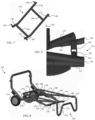
FIG. 7 shows a side perspective view of the intermediate support members of the table saw assembly ofFIG. 1 . -
FIG. 8 shows a side perspective view of the table saw assembly ofFIG. 1 with the stand in a closed horizontal configuration with the table saw removed for clarity. -
FIG. 9 shows a bottom perspective view of a tube stop of the table saw assembly ofFIG. 1 . -
FIG. 10 shows a rear perspective view of the latching assembly of the table saw assembly ofFIG. 1 . -
FIG. 11 shows a side plan view of the latch of the latching assembly ofFIG. 10 . -
FIG. 12 shows a side plan view of the table saw assembly ofFIG. 1 with the table saw removed for clarity and the stand in closed upright configuration. -
FIG. 13 shows a side plan view of the table saw assembly ofFIG. 1 with the table saw removed for clarity and the stand in an intermediate configuration. - For the purposes of promoting an understanding of the principles of the disclosure, reference will now be made to the embodiments illustrated in the drawings and described in the following written specification. It is understood that no limitation to the scope of the disclosure is thereby intended. It is further understood that the present disclosure includes any alterations and modifications to the illustrated embodiments and includes further applications of the principles of the disclosure as would normally occur to one skilled in the art to which this disclosure pertains.
-
FIG. 1 depicts atable saw assembly 100 which includes atable saw 102 and astand 104. The table saw 102 is shown in a horizontal position. As used herein, a "horizontal position" of a power tool is defined as the position at which the power tool is placed when the power tool is being used to perform work. In some embodiments, thestand 104 is used with any other desired power tool such as a router, a miter saw, etc. Thestand 104 is further depicted inFIG. 2 in an open configuration with the table saw 102 removed for convenience of describing the stand . - The
stand 104 includes acoupling assembly 106 which includes a generallyU-shaped support 108. In some embodiments, the table saw 104 is directly attached to theU-shaped support 108. In other embodiments, additional components are provided as part of the table saw coupling assembly to assist in mounting the table saw 104. For example,U.S. Patent No. 8,047,553 describes mounting structures which may be mounted to theU-shaped support 108. Additionally, in some embodiments the support structure is rectangular. - The
coupling assembly 106 is pivotably mounted tolongitudinal support members pivots longitudinal support members FIG. 3 , are joined at one end by a W-shapedhandle 118 and at the other end by avertical stabilizer 120. While shown as separately formed components, two or more of thelongitudinal support members handle 118, and thevertical stabilizer 120 are, in other embodiments, integrally formed. - Two
support pads vertical stabilizer 120 and twoanti-tip feet longitudinal support members anti-tip feet anti-tip foot 126 shown inFIGs. 4 and 5 . - The
anti-tip foot 126 includes a hardplastic foot 130 and asoft rubber pad 132. As shown inFIG. 5 , thesoft rubber pad 132 is configured to extend downwardly farther than the hard plastic foot when the anti-tip foot is positioned on a surface. Accordingly, the soft rubber pad inhibits sliding of thestand 104. The lowermost portion of thesoft rubber pad 132 and the lower most portion of the hardplastic foot 130, however, define anangle 134. In the event a force is applied to thestand 104 which causes tipping of the stand above theangle 134, the hardplastic foot 130 is brought into contact with the underlying surface and thesoft rubber pad 132 is lifted off of the surface. Accordingly, thesoft rubber pad 132 no longer inhibits slipping and the hardplastic foot 130 enables slipping. Consequently, the stand will slide across the surface rather than tip over. Moreover, by the incorporation of hard plastic, the use of metal, which can scratch soft surfaces such as wood floors, is avoided. - Returning to
FIGs. 1 and2 , tube stops 134 and 136 are provided on thelongitudinal support members coupling assembly 106. Curvedprotective plates longitudinal support members pivots coupling assembly 106, thelongitudinal support members lower support members pivots - The
lower support members 142/144, which are joined by a wheel support member 150 (seeFIG. 6 ) are rotatably connected towheels lower support members 142/144 andwheel support member 150 are separately formed. Thelower support members 142/144 includelower legs 156/158 andupper legs 160/162, respectively. Thewheel support member 150 joins thelower support members 142/144 at a lower portion of thelower legs 156/158. Theupper legs 160/162 extend from thelower legs 156/158 at a non-zero angle in a direction toward thecoupling assembly 106 when the stand is in the open position shown inFIG. 2 . Thepivots lower support members 142/144 to thelongitudinal support members 110/112, respectively, are operably connected to theupper legs 160/162, respectively. - Also operably connected to the
upper legs 160/162 arepivots 164/166 (seeFIG. 2 ) which pivotably connect thelower support members 142/144 tointermediate support members 168/170 (see, also,FIG. 7 ), respectively. More specifically, thepivots 164/166 are operably connected toupper arms 172/174 of theintermediate support members 168/170, respectively. Theupper arms 172/174 are connected to lowerarms 176/178, respectively, which are shown more clearly inFIG. 7 . Locking pins 180/182 extend from thelower arms 176/178, respectively. Theupper arms 172/174 extend at a non-zero angle from thelower arms 176/178, respectively in a direction toward the table sawcoupling assembly 106 when thestand 104 is in the open position ofFIG. 2 . - The
intermediate support members 168/170 are joined byupper crossbar 184 andlower crossbar 186. In the embodiment ofFIG. 7 , theintermediate support members 168/170, lockingpins 180/182, andcrossbars 184/186 are integrally formed. In other embodiments, one or more of theintermediate support members 168/170, lockingpins 180/182, andcrossbars 184/186 are separately formed. Theintermediate support members 168/170 are also pivotably connected to thecoupling assembly 106 throughpivots 188/190, respectively. Thepivots 188/190 are operably connected to theupper arms 172/174, respectively. - Further details regarding the table saw
assembly 100 including operation of thestand 104 are described with initial reference toFIG. 8 . InFIG. 8 , which shows the table sawassembly 100 with the table saw 102 removed for clarity, thestand 104 is in a closed horizontal position. In the closed horizontal position, the table sawassembly 100 is supported on a surface with thewheels 152/154 and the W-shapedhandle 118. In addition to support provided through thepivots coupling assembly 106 is supported in the closed horizontal position by the tube stops 134/136. The tube stops are similarly configured and are described in more detail with reference to tube stop 136 as shown inFIGs. 2 and9 . - As shown in
FIG. 2 , thetube stop 136 is rigidly attached to thelongitudinal support member 112. Thetube stop 136 is configured to extend inwardly in a direction toward thelongitudinal support member 110. Accordingly, when the stand is in the closed horizontal configuration ofFIG. 8 , thetube stop 136 is positioned directly between thecoupling assembly 106 and thelower leg 158. - In particular, the
tube stop 136 includes arectangular tube portion 200, which is shown inFIG. 9 , which is welded to thelongitudinal support member 112. An upper surface of therectangular tube portion 200 is configured to contact thecoupling assembly 106. At a lower portion of the rectangular tube portion 200 anut 202 is welded to therectangular tube portion 200. Abolt 204 extending through thenut 202 thus sets a precise spacing of thecoupling assembly 106 and thelower leg 158, and thus the other support members of thestand 104. This provides increased strength such that the stand is not over-compressed in the event that additional loading is applied to the table saw when the stand is in the closed horizontal position. In some embodiments, the tube stop is alternatively mounted to one of the intermediate support member and the table saw coupling assembly. - With reference to
FIG. 8 , in order to move the table sawassembly 100, a user grasps the W-shapedhandle 118. Because of the design of the W-shapedhandle 118, when the stand is in the closed horizontal position, the W-shapedhandle 118 provides an elevated portion 204 (seeFIG. 8 ). Consequently, a user does not need to reach down as far to grab the W-shapedhandle 118. The W-shaped handle is then used to pivot thestand 104 about thewheels 152/154 so that the table sawassembly 100 can be maneuvered using thewheels 152/154. - To assist in safely moving the table saw
assembly 104, the table saw assembly is locked in the closed position using a latchingassembly 210 which is described with reference toFIGs. 6 ,10, and 11 . The latchingassembly 210 includes afoot pedal 212 which is rigidly connected to a connectingplate 214 such that pivoting of thefoot pedal 212 causes pivoting of the connectingplate 214. Thefoot pedal 212 and connectingplate 214 are pivotably connected to thelower support member 142 through apivot 216. Thefoot pedal 212 and connectingplate 214 are biased to place the latchingassembly 210 in a locking position shown inFIG. 10 by a spring 215 (seeFIG. 6 ) or other biasing member between thefoot pedal 212 and connectingplate 214 and thelower support member 142. The biasing force acts in a counterclockwise direction about thepivot 216 in the view shown inFIG. 10 . Mounting of thefoot pedal 212 within the footprint of thewheel support member 150 protects thefoot pedal 212 from accidental activation. - Continuing with
FIG. 10 , the connectingplate 214 is pivotably connected to alatch 218 through apivot 220 which in this embodiment is a screw. The screw/pivot 220 rotatably extends through pivot bore 222 in thebody 224 of thelatch 218 which is shown inFIG. 11 . Thelatch 218 includes anactivation surface 226, anactivation surface 228, and a receivinggroove 230. Thebody 224 further includes aslot 232. Thelatch 218 is slidably mounted to thelower support member 142 by ascrew 234 fixedly connected to the lower support member 142 (seeFIG. 10 ). - When the stand is in a closed position such as the closed horizontal position shown in
FIG. 8 , alocking pin 236 is positioned within the receivingslot 230. Thelocking pin 236 is fixedly connected to thelongitudinal support member 110. Accordingly, the stand is locked in the closed position. Therefore, a user can maneuver the table sawassembly 100 without thestand 104 moving to an open position. Moreover, the curvedprotective plates 138/140 are configured such that when the stand is in the closed horizontal position ofFIG. 8 , a curved lower edge of each of the protective plates (see, e.g., curvededges 238 and 240) extends farther downwardly than a lowermost portion 242 (seeFIG. 10 ) of the lockinglatch 218. This provides protection for thelatch assembly 210 when the stand is in the closed position, and provides protection from accidental operation of the latch assembly 201. Thecurved edges assembly 100 is loaded into a vehicle or moving along stairs. - To position the table saw
assembly 100 for operation once the table sawassembly 100 has been transported to a desired location, the table sawassembly 100 is moved from the closed horizontal position ofFIG. 8 to a closed upright position as depicted inFIG. 12 . To move from the horizontal closed position to the vertical closed position ofFIG. 12 a user lifts the W-shaped handle while using thewheels 152/154 as pivots, until thevertical stabilizer 120 contacts an underlying surface. More specifically, thesupport pads 122/124 come into contact with the underlying surface. Stability of the table sawassembly 100 is provided by the latchingassembly 210 during this movement which precludes opening of thestand 104. - In the closed upright position of
FIG. 12 , thevertical stabilizer 120, along with thewheels 152/154, maintains the table sawassembly 100 in a stable vertical position so long as thelocking pin 236 is maintained within thegroove 230 of thelatch 218. In the locked upright closed position ofFIG. 12 the wheel axles (see, e.g.,wheel axle 244 of wheel 152) are located to the left of avertical plane 250 in which apivot axis 252 of thepivots pivots vertical plane 250. Additionally, the table saw 102 (not shown inFIG. 12 ) is located to the right of thevertical plane 250 in a substbatially vertical position. Thus, the weight of the table saw 102 acting through thepivots 146/148 and the axle(s) 244 provides a force tending to push thewheels 152/154 in a leftwardly direction. The latchingassembly 210, however, prevents this movement. - When the user desires to move the table saw assembly into an open position, the user depresses the foot pedal 212 (see
FIGs. 6 and10 ) which acts against the biasing force of thespring 215 causing the connectingplate 214 to rotate in a clockwise direction (in the view ofFIG. 10 ). Pivoting of the connectingplate 214 causes thelatch 218 to move downwardly guided by thescrew 234 within theslot 232 until thelocking pin 236 is no longer within the receivinggroove 230. - Once the
locking pin 236 is no longer within the receivinggroove 230, relative movement between thelongitudinal support member 110 and thelower support member 142 is no longer constrained. Consequently, the force resulting from the weight of the table saw 102 causes thelower support members 142/144 to automatically pivot about thelongitudinal support members 110/112, respectively by way of thepivots 146/148 respectively as thewheels 152/154 move away from thevertical plane 250. Once thelocking pin 236 is no longer aligned with the receivinggroove 230, the user removes the user force fromfoot pedal 212 and thespring 215 causes the connecting plate 214 (and foot pedal 212) to rotate in a counter-clockwise direction (in the view ofFIG. 6 ). Counter-clockwise pivoting of the connectingplate 214 causes thelatch 218 to move upwardly guided by thescrew 234 within theslot 232 to the locking position shown inFIG. 10 (but without the lockingpin 236 in the groove 230). - The pivoting of the
lower support members 142/144 about thepivots 146/148 cause theupper legs 160/162 to pivot in a clockwise direction as indicated by thearrow 254 inFIG. 12 . The automatic movement of the table saw assembly away from the closed upright position continues until the table saw assembly reaches an intermediate position shown inFIG. 13 at which point the automatic movement of the table sawassembly 100 ceases. - The table saw
assembly 100 is rotationally stable in the intermediate position ofFIG. 13 whereat the table saw is in a less vertical orientation compared to the configuration ofFIG. 12 because thepivots 164/166 have moved to a location immediately adjacent to or in line with thevertical plane 250 as the center of gravity of the table saw has moved toward thevertical plane 250. With thepivots 164/166 and thepivots 146/148 stacked in this manner, the table sawassembly 100 is stable. To continue from the intermediate position ofFIG. 13 the user simply presses downwardly on the W-shapedhandle 118. This additional force allows the table sawassembly 100 to continue toward the open position shown inFIG. 2 . - Specifically, as the W-shaped
handle 118 moves downwardly under the force provided by the user, thelongitudinal support members 110/112 rotate leftwardly and contact with the underlying support surface shifts from thesupport pads 122/124 to theanti-tip feet 126/128. In some embodiments, thesupport pads 122/124 and theanti-tip feet 126/128 are configured to simultaneously be in contact with the underlying support surface. In other embodiments, contact moves from thesupport pads 122/124 to the connections between thevertical stabilizer 120 and thelongitudinal support members 110/112. Thewheels 152/154 continue to move away from thevertical plane 250 throughout the change in contact from thesupport pads 122/124 to theanti-tip feet 126/128. - As the table saw assembly continues to move toward the open positon of
FIG. 2 , the lockingpin 180 comes into contact with theactivation surface 226 of thelatch 218. This contact presses thelatch 218 downwardly causing the connectingplate 214 to rotate against the biasing force of thespring 215. This movement continues until thelocking pin 180 moves into thegroove 230 at which time thespring 215 causes the connecting plate 214 (and foot pedal 212) to rotate in a counter-clockwise direction (in the view ofFIG. 10 ). Counter-clockwise pivoting of the connectingplate 214 causes thelatch 218 to move upwardly guided by thescrew 234 within theslot 232 thereby locking thelocking pin 180 within the receivinggroove 230. - At or about the same time as the
locking pin 180 is being locked by thelatch 218, the locking pins 180/182 also move into contact with thelower support members 140/142. Further movement away from the intermediate position ofFIG. 13 is thereby terminated and the table sawassembly 100 is in the open position ofFIG. 2 with the table saw in a substantially horizontal configuration. Accordingly, the table saw 102 is in position for use. The user may then use the table saw 102 as desired. - When the user desires to place the table saw
assembly 100 in a closed position from the open position ofFIG. 2 , the user pivots thefoot pedal 212 in a clockwise direction (as viewed inFIG. 10 ) by overcoming the biasing force of thespring 215. The clockwise pivoting of thefoot pedal 212 causes the connectingplate 214 to pivot in a clockwise direction about thepivot 216 thereby forcing thelatch 218 downwardly. Once thelatch 218 has moved downwardly to a sufficient extent, the lockingpin 180 is no longer constrained within thegroove 230. The user then lifts upwardly with the W-shapedhandle 118. This causes thelongitudinal support members anti-tip feet 126/128 and thewheels 152/154 begin to move toward thevertical plane 250 due to the weight of the table saw 102 acting through theintermediate support members 168/170 and thepivots 164/166. - As the user continues to lift the W-shaped
handle 118, contact with the underlying support surface moves from theanti-tip feet 126/128 to thesupport pads 122/124 in a manner opposite that described above with respect to movement to the open position ofFIG. 2 and the table sawassembly 100 comes to the intermediate position ofFIG. 13 . From the intermediate position ofFIG. 13 , the user pushes the W-shapedhandle 118 in a forward direction toward thevertical plane 250 allowing thewheels 152/154 to move closer to thevertical plane 250. - As the
wheels 152/154 move closer to thevertical plane 250, the lockingpin 236 which is fixedly connected to thelongitudinal support member 110 contacts theactivation surface 228 of thelatch 218. This forces thelatch 218 downwardly causing the connectingplate 214 to rotate against the biasing force of thespring 215. This movement continues until thelocking pin 236 moves into thegroove 230 at which time thespring 215 causes the connecting plate 214 (and foot pedal 212) to rotate in a counter-clockwise direction (in the view ofFIG. 10 ). Counter-clockwise pivoting of the connectingplate 214 causes thelatch 218 to move upwardly guided by thescrew 234 within theslot 232 thereby locking thelocking pin 236. - At or about the same time as the
locking pin 236 is being locked by thelatch 218, the tube stops 134/136 move into contact with thecoupling assembly 106 and the lower support member 150 (seeFIG. 9 ). Further movement away from the intermediate position ofFIG. 13 is thereby terminated and the table sawassembly 100 is in the closed upright position ofFIG. 12 with the table saw in a substantially vertical configuration. Accordingly, the table sawassembly 100 can be safely moved as desired. - The configuration of the
stand 104 thus provides for automatic movement from the closed upright position ofFIG. 12 to the intermediate position ofFIG. 13 using two pivot axes. One pivot axis is defined by thepivots 146/148 and the other pivot axis is defined by thepivots 164/166. Optimally, the pivot axis defined by thepivots 164/166 is positioned at a distance x from thevertical plane 250 when thestand 104 is in a closed upright position, wherein 0.25" ≥ x ≤ 3". The pivot axis defined by thepivots 164/166 is positioned at a distance y from ahorizontal plane 256 in which thepivot axis 252 extends when thestand 104 is in a closed upright position, wherein 1.0" ≥ y ≤ 6". The geometry created by these distances is such that when the stand is in the closed position and the foot pedal is pressed, the weight of the saw causes the automatic movement to the stable intermediate position ofFIG. 13 , requiring less effort from the user to open the stand. - While the disclosure has been illustrated and described in detail in the drawings and foregoing description, the same should be considered as illustrative and not restrictive in character. It is understood that only the preferred embodiments have been presented and that all changes, modifications and further applications that come within the spirit of the disclosure are desired to be protected.
Claims (20)
- A table saw system, comprising:a table saw; anda stand configured to support the table saw, the stand includinga table saw coupling assembly configured to couple with the table saw,an intermediate support member pivotably coupled to the table saw coupling assembly through at least one first pivot,a lower support member pivotably coupled to the intermediate support member through at least one second pivot, anda longitudinal support member pivotably connected to the table saw coupling assembly through at least one third pivot, and pivotably connected to the lower support member through at least one fourth pivot,whereinthe stand is movable between a closed upright position whereat the table saw is generally vertically oriented, an open position whereat the table saw is generally horizontally oriented, and an intermediate position from which the stand is alternatively movable to either of the closed upright position and the open position without passing through the other of the closed position and the open position,the table saw is generally vertically oriented in the intermediate position,the at least one second pivot is closer to a vertical plane in which a pivot axis of the at least one fourth pivot extends when the stand is in the intermediate position than when the stand is in the closed upright position, andthe stand is configured to move from the closed upright position to the intermediate position automatically when the table saw is coupled to the table saw coupling assembly.
- The table saw system of claim 1, wherein when the stand is in the closed upright position:a minimum distance between the at least one second pivot and a vertical plane extending through the fourth pivot is ≥ 0.25 inches and ≤ 3 inches; anda minimum distance between a horizontal plane extending through the at least one second pivot and a horizontal plane extending through the at least one fourth pivot is ≥ 1 inch and ≤ 6 inches.
- The table saw system of claim 2, further comprising:
a tube stop assembly mounted on one of the lower support member, the intermediate support member, and the table saw coupling assembly, the tube stop assembly configured to abut the other two of the lower support member, the intermediate support member, and the table saw coupling assembly when the stand is in a closed horizontal position. - The table saw system of claim 3, wherein the tube stop assembly comprises a stop bolt configured to contact one of the intermediate support member, and the table saw coupling assembly when the stand is in the closed horizontal position.
- The table saw assembly of claim 3, wherein the intermediate support member has a first end portion and a second end portion opposite the first end portion, the table saw assembly further comprising:a locking pin at the second end portion of the intermediate support member;a locking latch slidably connected to the lower support member; anda foot actuator pivotably connected to the lower support member and the locking latch, whereinthe locking pin and locking latch are configured to automatically lock the stand when the stand is moved to the open position,the foot actuator is configured to unlock the locking pin and locking latch when the foot actuator is moved from a first position to a second position, andthe locking pin is configured to contact the lower support member in the open position.
- The table saw assembly of claim 5, further comprising:a protective plate mounted on the longitudinal support,whereinthe protective plate is configured such that when the stand is in a closed horizontal position a lower edge of the protective plate extends farther downwardly than a lowermost portion of the locking latch, andthe lower edge is rounded.
- The table saw assembly of claim 6, further comprising:
at least one wheel rotatably connected to the lower support member. - The table saw assembly of claim 6, further comprising:
a vertical stabilizer extending from the longitudinal support, the vertical stabilizer configured to maintain the stand in a vertical condition when the stand is in the closed upright position and the intermediate position. - The table saw assembly of claim 8, wherein:the lower support member includes a lower leg and an upper leg;the second and fourth pivots are operably connected to the upper leg;when the stand is in the open position, the upper leg extends at a non-zero angle from the lower leg in a direction toward the table saw coupling assembly;the intermediate support member includes an upper arm and a lower armthe first and second pivots are operably connected to the upper arm; andwhen the stand is in the open position, the upper arm extends at a non-zero angle from the lower arm in a direction toward the table saw coupling assembly.
- The table saw assembly of claim 1, further comprising:
a latching assembly movable between a locking position and an unlocked position, wherein the stand is configured to move from the closed upright position to the intermediate position automatically when the table saw is coupled to the table saw coupling assembly and the latching assembly is moved from the locking position to the unlocked position. - The table saw assembly of claim 10, wherein the intermediate support member has a first end portion and a second end portion opposite the first end portion, the latching assembly comprising:a locking pin at the second end portion of the intermediate support member;a locking latch slidably connected to the lower support member; anda foot actuator pivotably connected to the lower support member and the locking latch.
- A stand for a power tool, comprising:a power tool coupling assembly configured to couple with the power tool;an intermediate support member pivotably coupled to the power tool coupling assembly through at least one first pivot;a lower support member pivotably coupled to the intermediate support member through at least one second pivot; anda longitudinal support member pivotably connected to the power tool coupling assembly through at least one third pivot, and pivotably connected to the lower support member through at least one fourth pivot,whereinthe stand is configured to be movable between a closed upright position whereat the power tool, when coupled to the stand, is generally vertically oriented, an open position whereat the power tool, when coupled to the stand, is generally horizontally oriented, and an intermediate position from which the stand is alternatively movable to either of the closed upright position and the open position without passing through the other of the closed position and the open position,the stand is configured such that the power tool, when coupled to the stand, is generally vertically oriented in the intermediate position,the at least one second pivot is closer to a vertical plane in which an axis of the at least one fourth pivot extends when the stand is in the intermediate position than when the stand is in the closed upright position, andthe stand is configured to move from the closed upright position to the intermediate position automatically when the power tool is coupled to the power tool coupling assembly.
- The stand of claim 12, wherein when the stand is in the closed upright position:a minimum distance between the at least one second pivot and a vertical plane extending through the fourth pivot is ≥ 0.25 inches and ≤ 3 inches; anda minimum distance between a horizontal plane extending through the at least one second pivot and a horizontal plane extending through the at least one fourth pivot is ≥ 1 inch and ≤ 6 inches.
- The stand of claim 13, further comprising:
a tube stop assembly mounted on one of the lower support member, the intermediate support member, and the table saw coupling assembly, the tube stop assembly configured to abut the other two of the lower support member, the intermediate support member, and the table saw coupling assembly when the stand is in a closed horizontal position. - The stand of claim 14, wherein the tube stop assembly comprises a stop bolt configured to contact one of the intermediate support member, and the table saw coupling assembly when the stand is in the closed horizontal position.
- The stand of claim 14, wherein the intermediate support member has a first end portion and a second end portion opposite the first end portion, the stand further comprising:a locking pin at the second end portion of the intermediate support member;a locking latch slidably connected to the lower support member; anda foot actuator pivotably connected to the lower support member and the locking latch, whereinthe locking pin and locking latch are configured to automatically lock the stand when the stand is moved to the open position,the foot actuator is configured to unlock the locking pin and locking latch when the foot actuator is moved from a first position to a second position, andthe locking pin is configured to contact the lower support member in the open position.
- The stand of claim 16, further comprising:a protective plate mounted on the longitudinal support,whereinthe protective plate is configured such that when the stand is in a closed horizontal position a lower edge of the protective plate extends farther downwardly than a lowermost portion of the locking latch, andthe lower edge is rounded.
- The stand of claim 17, wherein:the lower support member includes a lower leg and an upper leg;the second and fourth pivots are operably connected to the upper leg;when the stand is in the open position, the upper leg extends at a non-zero angle from the lower leg in a direction toward the power tool coupling assembly;the intermediate support member includes an upper arm and a lower armthe first and second pivots are operably connected to the upper arm; andwhen the stand is in the open position, the upper arm extends at a non-zero angle from the lower arm in a direction toward the power tool coupling assembly.
- The stand of claim 12, further comprising:
a latching assembly movable between a locking position and an unlocked position, wherein the stand is configured to move from the closed upright position to the intermediate position automatically when the power tool is coupled to the power tool coupling assembly and the latching assembly is moved from the locking position to the unlocked position. - The table saw assembly of claim 19, wherein the intermediate support member has a first end portion and a second end portion opposite the first end portion, the latching assembly comprising:a locking pin at the second end portion of the intermediate support member;a locking latch slidably connected to the lower support member; anda foot actuator pivotably connected to the lower support member and the locking latch.
Applications Claiming Priority (1)
| Application Number | Priority Date | Filing Date | Title |
|---|---|---|---|
| US18/545,803 US12502720B2 (en) | 2023-12-19 | 2023-12-19 | Table saw with gravity rise stand |
Publications (1)
| Publication Number | Publication Date |
|---|---|
| EP4574344A1 true EP4574344A1 (en) | 2025-06-25 |
Family
ID=93796721
Family Applications (1)
| Application Number | Title | Priority Date | Filing Date |
|---|---|---|---|
| EP24217196.5A Pending EP4574344A1 (en) | 2023-12-19 | 2024-12-03 | Table saw with rise stand |
Country Status (3)
| Country | Link |
|---|---|
| US (1) | US12502720B2 (en) |
| EP (1) | EP4574344A1 (en) |
| CN (1) | CN120170846A (en) |
Citations (6)
| Publication number | Priority date | Publication date | Assignee | Title |
|---|---|---|---|---|
| CN2802248Y (en) * | 2005-07-01 | 2006-08-02 | 圣杰机器工业股份有限公司 | Stands for supporting power tools |
| US20070012826A1 (en) * | 2005-06-29 | 2007-01-18 | Durq Machinery Corp. | Mobile power tool stand |
| US8047553B2 (en) | 2008-05-22 | 2011-11-01 | Robert Bosch Gmbh | Collapsible rolling support stand having a support leg |
| US10005178B1 (en) * | 2016-12-06 | 2018-06-26 | Rexon Industrial Corp., Ltd. | Collapsible stand |
| CN108612992A (en) * | 2016-12-13 | 2018-10-02 | 力山工业股份有限公司 | Foldable support frame |
| CN210389116U (en) * | 2019-08-17 | 2020-04-24 | 金华市亚虎工具有限公司 | Bent pipe oblique fracture saw support |
Family Cites Families (21)
| Publication number | Priority date | Publication date | Assignee | Title |
|---|---|---|---|---|
| US5087013A (en) | 1988-01-29 | 1992-02-11 | Emerson Electric Co. | Foldable stand for threading machine |
| US6848684B2 (en) * | 2002-09-17 | 2005-02-01 | Black & Decker Inc. | Workbench having plastic clamping work surface |
| US20040187666A1 (en) * | 2003-03-25 | 2004-09-30 | Durq Machinery Corp. | Table saw |
| WO2005016601A2 (en) * | 2003-08-05 | 2005-02-24 | Black & Decker Inc. | Folding bench with hand truck capabilities |
| US8096519B2 (en) | 2004-03-12 | 2012-01-17 | Robert Bosch Gmbh | Collapsible rolling support stand |
| US7077421B2 (en) | 2004-09-24 | 2006-07-18 | Super Made Products Co., Ltd. | Table saw cart |
| TWI243733B (en) | 2004-10-07 | 2005-11-21 | P & F Brother Ind Corp | Movable machine tool retaining frame |
| US7588255B2 (en) * | 2004-11-10 | 2009-09-15 | Zag Industries, Ltd. | Collapsible clamping work table |
| TWD111051S1 (en) | 2005-05-05 | 2006-05-21 | 聖傑機器工業股份有限公司 | Supporting scaffold |
| CN100398266C (en) | 2006-02-27 | 2008-07-02 | 苏州市新大地五金制品有限公司 | Folding cutting machine working stand |
| TW200815169A (en) * | 2006-09-18 | 2008-04-01 | Durq Machinery Corp | Support structure for table type tool |
| US8464994B2 (en) | 2008-10-22 | 2013-06-18 | Rexon Industrial Corp., Ltd. | Folding tool stand |
| CN101745904B (en) | 2008-12-11 | 2012-05-30 | 苏州宝时得电动工具有限公司 | Power tool bracket |
| US8454717B2 (en) | 2010-10-12 | 2013-06-04 | Tony Lin | Foldable dust collector |
| US8910970B2 (en) * | 2011-06-10 | 2014-12-16 | Rexon Industrial Corp., Ltd. | Rapidly collapsible stand |
| US9149926B2 (en) | 2011-06-17 | 2015-10-06 | Rexon Industrial Corp., Ltd. | Collapsible stand |
| US9186736B1 (en) * | 2014-05-18 | 2015-11-17 | Chin-Chin Chang | Collapsible stand for table saw |
| US20190116999A1 (en) | 2017-10-24 | 2019-04-25 | Lily Ann Born | Cup Resistant to Both Slipping and Tipping |
| US11027411B2 (en) | 2018-10-24 | 2021-06-08 | Tti (Macao Commercial Offshore) Limited | Saw stand |
| US11890744B2 (en) * | 2020-07-31 | 2024-02-06 | Techtronic Cordless Gp | Workbench-hand truck assembly |
| US20240042538A1 (en) * | 2022-08-02 | 2024-02-08 | Milwaukee Electric Tool Corporation | Portable pipe threader |
-
2023
- 2023-12-19 US US18/545,803 patent/US12502720B2/en active Active
-
2024
- 2024-12-03 EP EP24217196.5A patent/EP4574344A1/en active Pending
- 2024-12-18 CN CN202411869597.3A patent/CN120170846A/en active Pending
Patent Citations (6)
| Publication number | Priority date | Publication date | Assignee | Title |
|---|---|---|---|---|
| US20070012826A1 (en) * | 2005-06-29 | 2007-01-18 | Durq Machinery Corp. | Mobile power tool stand |
| CN2802248Y (en) * | 2005-07-01 | 2006-08-02 | 圣杰机器工业股份有限公司 | Stands for supporting power tools |
| US8047553B2 (en) | 2008-05-22 | 2011-11-01 | Robert Bosch Gmbh | Collapsible rolling support stand having a support leg |
| US10005178B1 (en) * | 2016-12-06 | 2018-06-26 | Rexon Industrial Corp., Ltd. | Collapsible stand |
| CN108612992A (en) * | 2016-12-13 | 2018-10-02 | 力山工业股份有限公司 | Foldable support frame |
| CN210389116U (en) * | 2019-08-17 | 2020-04-24 | 金华市亚虎工具有限公司 | Bent pipe oblique fracture saw support |
Also Published As
| Publication number | Publication date |
|---|---|
| US12502720B2 (en) | 2025-12-23 |
| CN120170846A (en) | 2025-06-20 |
| US20250196239A1 (en) | 2025-06-19 |
Similar Documents
| Publication | Publication Date | Title |
|---|---|---|
| US8602378B2 (en) | Collapsible rolling support stand | |
| US8047553B2 (en) | Collapsible rolling support stand having a support leg | |
| US6857836B2 (en) | Wheeled transports | |
| US8152149B2 (en) | Folding bench with three member top | |
| US20020125662A1 (en) | Combination lifting, platform, handtruck, scaffold, floorjack and mechanic cleeper | |
| US5957649A (en) | Lift dolly for use in conjunction with stand-mounted power tools and the like | |
| US20060180244A1 (en) | Portable work bench | |
| US4726405A (en) | Extension table assembly for table saws | |
| US4645162A (en) | Leg support structure | |
| US10813446B2 (en) | Collapsible infeed/outfeed table with shelf | |
| US2846233A (en) | Table truck | |
| EP4574344A1 (en) | Table saw with rise stand | |
| US9376130B1 (en) | Self-jacking mobile saw stand WA9940 | |
| EP1816051A2 (en) | Trolley, particularly for moving pieces of furniture | |
| US20100303593A1 (en) | Adjustable lift dolly which is used in connection with stand-mounted equipment, power tools and similer items | |
| AU719723B1 (en) | A trolley | |
| CN212938953U (en) | Saw horse stool | |
| CN201350625Y (en) | Foldable self-elevating movable electric tool table | |
| EP2153945A1 (en) | Self-Jacking mobile saw stand | |
| US20240416983A1 (en) | Reconfigurable Materials Handling Cart | |
| US10155525B1 (en) | Folding foot-kick for hand truck | |
| AU2006100446A4 (en) | Demountable tray system for vehicles | |
| US321902A (en) | Hand-truck |
Legal Events
| Date | Code | Title | Description |
|---|---|---|---|
| STAA | Information on the status of an ep patent application or granted ep patent |
Free format text: STATUS: UNKNOWN |
|
| PUAI | Public reference made under article 153(3) epc to a published international application that has entered the european phase |
Free format text: ORIGINAL CODE: 0009012 |
|
| STAA | Information on the status of an ep patent application or granted ep patent |
Free format text: STATUS: THE APPLICATION HAS BEEN PUBLISHED |
|
| AK | Designated contracting states |
Kind code of ref document: A1 Designated state(s): AL AT BE BG CH CY CZ DE DK EE ES FI FR GB GR HR HU IE IS IT LI LT LU LV MC ME MK MT NL NO PL PT RO RS SE SI SK SM TR |
|
| STAA | Information on the status of an ep patent application or granted ep patent |
Free format text: STATUS: REQUEST FOR EXAMINATION WAS MADE |
|
| 17P | Request for examination filed |
Effective date: 20260102 |