EP4574309A1 - Method of manufacturing a turbine shroud segment - Google Patents
Method of manufacturing a turbine shroud segment Download PDFInfo
- Publication number
- EP4574309A1 EP4574309A1 EP24220358.6A EP24220358A EP4574309A1 EP 4574309 A1 EP4574309 A1 EP 4574309A1 EP 24220358 A EP24220358 A EP 24220358A EP 4574309 A1 EP4574309 A1 EP 4574309A1
- Authority
- EP
- European Patent Office
- Prior art keywords
- shroud segment
- turbine shroud
- green part
- radially outer
- drilling
- Prior art date
- Legal status (The legal status is an assumption and is not a legal conclusion. Google has not performed a legal analysis and makes no representation as to the accuracy of the status listed.)
- Pending
Links
Images






Classifications
-
- B—PERFORMING OPERATIONS; TRANSPORTING
- B22—CASTING; POWDER METALLURGY
- B22F—WORKING METALLIC POWDER; MANUFACTURE OF ARTICLES FROM METALLIC POWDER; MAKING METALLIC POWDER; APPARATUS OR DEVICES SPECIALLY ADAPTED FOR METALLIC POWDER
- B22F3/00—Manufacture of workpieces or articles from metallic powder characterised by the manner of compacting or sintering; Apparatus specially adapted therefor ; Presses and furnaces
- B22F3/22—Manufacture of workpieces or articles from metallic powder characterised by the manner of compacting or sintering; Apparatus specially adapted therefor ; Presses and furnaces for producing castings from a slip
- B22F3/225—Manufacture of workpieces or articles from metallic powder characterised by the manner of compacting or sintering; Apparatus specially adapted therefor ; Presses and furnaces for producing castings from a slip by injection molding
-
- B—PERFORMING OPERATIONS; TRANSPORTING
- B23—MACHINE TOOLS; METAL-WORKING NOT OTHERWISE PROVIDED FOR
- B23P—METAL-WORKING NOT OTHERWISE PROVIDED FOR; COMBINED OPERATIONS; UNIVERSAL MACHINE TOOLS
- B23P15/00—Making specific metal objects by operations not covered by a single other subclass or a group in this subclass
-
- B—PERFORMING OPERATIONS; TRANSPORTING
- B22—CASTING; POWDER METALLURGY
- B22F—WORKING METALLIC POWDER; MANUFACTURE OF ARTICLES FROM METALLIC POWDER; MAKING METALLIC POWDER; APPARATUS OR DEVICES SPECIALLY ADAPTED FOR METALLIC POWDER
- B22F3/00—Manufacture of workpieces or articles from metallic powder characterised by the manner of compacting or sintering; Apparatus specially adapted therefor ; Presses and furnaces
- B22F3/24—After-treatment of workpieces or articles
-
- B—PERFORMING OPERATIONS; TRANSPORTING
- B22—CASTING; POWDER METALLURGY
- B22F—WORKING METALLIC POWDER; MANUFACTURE OF ARTICLES FROM METALLIC POWDER; MAKING METALLIC POWDER; APPARATUS OR DEVICES SPECIALLY ADAPTED FOR METALLIC POWDER
- B22F5/00—Manufacture of workpieces or articles from metallic powder characterised by the special shape of the product
- B22F5/009—Manufacture of workpieces or articles from metallic powder characterised by the special shape of the product of turbine components other than turbine blades
-
- F—MECHANICAL ENGINEERING; LIGHTING; HEATING; WEAPONS; BLASTING
- F01—MACHINES OR ENGINES IN GENERAL; ENGINE PLANTS IN GENERAL; STEAM ENGINES
- F01D—NON-POSITIVE DISPLACEMENT MACHINES OR ENGINES, e.g. STEAM TURBINES
- F01D25/00—Component parts, details, or accessories, not provided for in, or of interest apart from, other groups
- F01D25/08—Cooling; Heating; Heat-insulation
- F01D25/12—Cooling
-
- B—PERFORMING OPERATIONS; TRANSPORTING
- B23—MACHINE TOOLS; METAL-WORKING NOT OTHERWISE PROVIDED FOR
- B23P—METAL-WORKING NOT OTHERWISE PROVIDED FOR; COMBINED OPERATIONS; UNIVERSAL MACHINE TOOLS
- B23P2700/00—Indexing scheme relating to the articles being treated, e.g. manufactured, repaired, assembled, connected or other operations covered in the subgroups
- B23P2700/06—Cooling passages of turbine components, e.g. unblocking or preventing blocking of cooling passages of turbine components
-
- F—MECHANICAL ENGINEERING; LIGHTING; HEATING; WEAPONS; BLASTING
- F05—INDEXING SCHEMES RELATING TO ENGINES OR PUMPS IN VARIOUS SUBCLASSES OF CLASSES F01-F04
- F05D—INDEXING SCHEME FOR ASPECTS RELATING TO NON-POSITIVE-DISPLACEMENT MACHINES OR ENGINES, GAS-TURBINES OR JET-PROPULSION PLANTS
- F05D2230/00—Manufacture
- F05D2230/10—Manufacture by removing material
-
- F—MECHANICAL ENGINEERING; LIGHTING; HEATING; WEAPONS; BLASTING
- F05—INDEXING SCHEMES RELATING TO ENGINES OR PUMPS IN VARIOUS SUBCLASSES OF CLASSES F01-F04
- F05D—INDEXING SCHEME FOR ASPECTS RELATING TO NON-POSITIVE-DISPLACEMENT MACHINES OR ENGINES, GAS-TURBINES OR JET-PROPULSION PLANTS
- F05D2230/00—Manufacture
- F05D2230/20—Manufacture essentially without removing material
- F05D2230/22—Manufacture essentially without removing material by sintering
Definitions
- the application relates generally to methods of manufacturing a turbine shroud segment for a gas turbine engine.
- Turbine shroud segments in gas turbine engines are exposed to hot gases and, thus, require cooling. Cooling air may be bled off from the compressor section, thereby reducing the amount of energy that can be used for the primary purpose of proving thrust. It is thus desirable to minimize the amount of air bleed from other systems to perform cooling.
- Various methods of cooling the turbine shroud segments may include directing the cooling flow through a core cavity within the turbine shroud segment. However, manufacturing turbine shroud segments including such feature has proven to be challenging.
- a method of manufacturing a turbine shroud segment for a gas turbine engine defining an engine axis comprising the steps of receiving a turbine shroud segment green part made of powder injection molding material, machining an axial cooling flow passageway in the turbine shroud segment green part to obtain a machined turbine shroud segment green part, the axial cooling flow passageway extending along a direction having a component in an axial direction relative to the engine axis when the turbine shroud segment is mounted to the gas turbine engine, and after the machining of the axial cooling flow passageway, debinding and sintering the machined turbine shroud segment green part.
- the machining the axial cooling flow passageway comprises peck drilling the axial cooling flow passageway with a drilling tool in a plurality of drilling cycles.
- the axial cooling flow passageway has a diameter
- the peck drilling comprises, during a drilling cycle of the plurality of drilling cycles, plunging the drilling tool through the turbine shroud segment green part to a distance corresponding to more than five times the diameter of the axial cooling flow passageway.
- the machining comprises blowing pressurized air on the drilling tool between two drilling cycles of the plurality of drilling cycles.
- the machining comprises blowing pressurized air in the axial cooling flow passageway between two drilling cycles of the plurality of drilling cycles.
- the drilling tool retracts completely out of the axial cooling flow passageway.
- a method of manufacturing a turbine shroud segment for a gas turbine engine defining an engine axis comprising the steps of receiving a turbine shroud segment green part made of powder injection molding material, the turbine shroud segment green part including a body extending axially between a leading edge and a trailing edge and circumferentially between a first lateral edge and a second lateral edge, the body having a radially outer surface and a radially inner surface, machining a textured surface on the radially outer surface of the body to obtain a machined turbine shroud segment green part, and after the machining of the textured surface, debinding and sintering the machined turbine shroud segment green part.
- the machining comprises forming a recessed portion on the radially outer surface.
- the machining further comprises forming a plurality of turbulators protruding from the recessed portion on the radially outer surface.
- the machining comprises forming each turbulator of the plurality of turbulators individually with a cutting tool.
- the plurality of turbulators includes one or more of stand-offs having a cylindrical shape, peaks, valleys and crosses.
- the machining comprises blowing pressurized air on at least one of the cutting tool and the turbulator being formed by the cutting tool.
- a method of manufacturing a turbine shroud segment for a gas turbine engine defining an engine axis comprising the steps of injecting powder injection molding material into a mold for forming a molded turbine shroud segment green part including a body extending axially between a leading edge and a trailing edge and circumferentially between a first lateral edge and a second lateral edge, the body having a radially outer surface and a radially inner surface, the mold having cavities defining negatives of features forming a textured surface on the radially outer surface of the body, and debinding and sintering the molded turbine shroud segment green part.
- the textured surface comprises a recessed portion on the radially outer surface.
- the textured surface comprises a plurality of turbulators protruding from the recessed portion on the radially outer surface.
- the plurality of turbulators includes stand-offs having a frustoconical shape.
- air is evacuated from within the mold via a vent defined in the mold.
- the vent is fluidly connected to the cavities of the mold defining the plurality of turbulators.
- the vent extends axially between adjacent support legs of the molded turbine shroud segment green part, the adjacent support legs extending radially outward from the radially outer surface of the turbine shroud segment green part.
- the vent further extends radially outward from the radially outer surface of the turbine shroud segment green part.
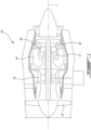
- Fig. 1 illustrates a gas turbine engine 10 of a type preferably provided for use in subsonic flight, generally comprising an annular gas path 11 disposed about an engine axis L.
- a fan 12, a compressor 14, a combustor 16 and a turbine 18 are axially spaced in serial flow communication along the gas path 11. More particularly, the engine 10 comprises a fan 12 through which ambient air is propelled, a compressor section 14 for pressurizing the air, a combustor 16 in which the compressed air is mixed with fuel and ignited for generating an annular stream of hot combustion gases, and a turbine 18 for extracting energy from the combustion gases.
- the turbine 18 includes turbine blades 20 mounted for rotation about the engine axis L.
- a turbine shroud assembly 22 extends circumferentially about the rotating blades 20.
- the shroud assembly 22 is disposed in close radial proximity to the tips 28 of the blades 20 and defines therewith a blade tip clearance 24 ( Fig. 2B ).
- the shroud assembly 22 includes a plurality of arcuate turbine shroud segments 26 spaced circumferentially to provide an outer flow boundary surface of the gas path 11 around the blade tips 28.
- each turbine shroud segment 26 has a body extending axially from a leading edge 30 to a trailing edge 32 and circumferentially between opposed axially extending sides or lateral edges 34.
- the terms “front” and “frontward” refer to a direction approaching the leading edge 30, while the terms “rear” and “rearward” refer to a direction approaching the trailing edge 32.
- the body has a radially inner surface 36 providing the outer flow boundary surface of the gas path 11 around the blade tip 28 and a radially outer surface 38 relative to the engine axis L.
- Front and rear support legs 40, 42 (e.g.
- hooks extend from the radially outer surface 38 to hold the shroud segment 26 into a surrounding fixed structure 44 of the engine 10, illustratively a casing for the shroud segment 26.
- the casing 44 includes impingement holes 46 for directing a flow of coolant C towards the radially outer surface 38 of the shroud, as will be discussed in further detail below.
- An optional top plate 48 may be affixed or otherwise installed above the casing 44, the top plate 48 including one or more additional impingement holes 50 for providing cooling to the casing 44.
- each shroud segment 26 has a cooling scheme directing a flow of coolant C across the radially outer surface 38 and through the body of the shroud segment 26 from a front or upstream end portion of the body of the shroud segment 26 to a rear or downstream end portion thereof, as will be discussed in further detail below. This may allow to take full benefit of the pressure delta between the leading edge 30 (the front end) and the trailing edge 32 (the rear end).
- a cooling plenum 52 is defined between the front and rear support legs 40, 42 and the casing 44 supporting the shroud segments 26. The cooling plenum 52 is connected in fluid flow communication to a source of the flow of coolant C.
- the coolant can be provided from any suitable source but is typically provided in the form of bleed air from one of the compressor stages. If the top plate 48 is present, an additional cooling plenum 54 may be defined between the top plate 48 and the casing 44, directing the flow of coolant C towards the impingement hole(s) 46 and providing a certain degree of cooling to the casing 44 if desired.
- the flow of coolant C exiting the impingement hole(s) 46 is directed or impinged onto a textured surface 56 on the radially outer surface 38.
- the textured surface 56 may promote heat transfer between the flow of coolant C and the shroud segment 26, for instance by increasing the wetted surface area of the radially outer surface 38 and/or by increasing the turbulence in the flow of coolant C.
- Various angles for the impingement hole(s) may be considered, for instance based on the desired level of cooling for the shroud segment 26.
- the impingement holes 46 direct the flow of coolant C in a radially inward direction towards the textured surface 56, while in the embodiment shown in Fig.
- the impingement holes 46 are angled towards the trailing edge 32 of the body of the shroud segment 26, thereby providing a rearward axial component. Other angles for the impingement hole(s) 46 may be contemplated as well. In various cases, the impingement holes 46 may be staggered axially along the casing 44 with respect to the engine axis L, distributing the impingement holes 46 along the casing 44 and thus improving the heat transfer between the flow of coolant C and the textured surface 56. Other positioning arrangements for the impingement holes 46 may be contemplated as well.
- the textured surface 56 may include peaks and valleys and/or turbulators to promote heat transfer between the shroud segment 26 and the flow of coolant C by increasing the wetted surface area and/or increasing the generated turbulence of the flow of coolant.
- the cooling scheme further includes a plurality of cooling inlets 58 for directing the flow of coolant C from the cooling plenum 52 into a front or upstream end of the body of the shroud segment 26 after the coolant C has interacted with the textured surface 56, as will be discussed in further detail below.
- the cooling inlets 58 are provided as a transverse row of inlet passages along the front support leg 40. The cooling inlets 58 then direct the flow of coolant C through a cooling flow passageway, illustratively a plurality of axial cooling flow passageways 60, passing through the body of the shroud segment 26.
- the cooling inlets 58 include inlet ends opening on the cooling plenum 52 just downstream (rearwardly) of the front support leg 40 and an outlet end opening to the cooling flow passageway underneath the front support leg 40, as will be discussed in further detail below.
- each cooling inlet 58 may be angled to receive the flow of coolant C from the cooling plenum 52.
- the angle of inclination of the cooling inlets 58 may be an acute angle as measured from the radially outer surface 38 of the shroud segment 26 and oriented to direct the coolant toward the leading edge 30 of the shroud segment 26.
- the inlets 58 are angled at about 45 degrees from the radially outer surface 38 of the shroud segment 26, although other angles may be contemplated as well.
- the acute angling of inlets 58 may direct the flow of coolant C towards the leading edge 30 within the body of the shroud segment 26, which may additionally promote heat transfer between the flow of coolant C and the shroud segment 26.
- the coolant may be conveniently accelerated as it is fed into the cooling flow passageway. The momentum gained by the coolant as it flows through the inlet passages may contribute to proving enhanced cooling at the front end portion of the shroud segment 26.
- the axial cooling flow passageways 60 are illustratively parallel cylindrical passageways. Other shapes for the axial passageways 60 may be contemplated as well. As discussed above, the axial passageways 60 begin at the cooling inlets 58 and follow a length of the body of the shroud segment 26 towards the trailing edge 32. In other words, the axial passageways 60 have a portion 60a thereof extending along a direction having a component in an axial direction relative to the engine axis L when the turbine shroud segment 26 is mounted to the gas turbine engine 10.
- a ratio of a length of the portion 60a the axial passageways 60 in the direction having a component in the axial direction relative to the engine axis L over the diameter of the axial passageway is greater than five, and in some implementations, greater than ten.
- the axial passageways 60 may promote heat transfer between the shroud segment 26, in particular from the radially inner surface 36, and the flow of coolant C.
- the number and dimensions of the axial passageways 60 may vary according to the cooling requirements of the shroud segment 26 and the overall dimensions of the shroud segment 26. For instance, a greater number of axial passageways 60 may be required to accommodate a greater flow of coolant C, while the diameter of the illustratively cylindrical axial passageways 60 may be limited by the overall thickness of the body of the shroud segment 26.
- the cooling scheme further comprises a plurality of cooling outlets 62 for discharging coolant from the axial passageways 60.
- the plurality of outlets 62 may include a row of outlet passages distributed along the trailing edge 32 of the shroud segment 26.
- the cooling outlets 62 are sized to meter the flow of coolant discharged through the trailing edge 32 of the shroud segment 26.
- the number of cooling inlets 58 and the number of cooling outlets 62 each correspond with the number of axial passageways 60.
- the axial passageways 60 may outnumber the cooling inlets 58 and cooling outlets 62 (or vice-versa), for instance if the axial passageways 60 were to converge or diverge towards the inlets 58 or outlets 62.
- a turbine shroud segment green part 26a is received.
- the turbine shroud segment green part 26a is formed using metal injection molding (MIM) techniques.
- MIM metal injection molding
- a feedstock is injected into a mold cavity to obtain a green part, also referred to herein as "green body".
- the feedstock can include high temperature resistant powder metal alloys, such as a nickel superalloy. Other high temperature resistant material powders which may include one material or a mix of materials could be used as well.
- the feedstock is a mixture of the material powder and of a binder which may include one or more binding material(s).
- the binder includes an organic material which is molten above room temperature (20°C) but solid or substantially solid at room temperature.
- the binder may include various components such as surfactants which are known to assist the injection of the feedstock into the mold for production of the green part.
- the binder includes a mixture of binding materials, for example including a lower melting temperature polymer, such as a polymer having a melting temperature below 100°C (e.g. paraffin wax, polyethylene glycol, microcrystalline wax) and a higher melting temperature polymer or polymers, such as a polymer or polymers having a melting temperature above 100°C (e.g. polypropylene, polyethylene, polystyrene, polyvinyl chloride).
- a lower melting temperature polymer such as a polymer having a melting temperature below 100°C (e.g. paraffin wax, polyethylene glycol, microcrystalline wax)
- a higher melting temperature polymer or polymers such as a polymer or polymers having a melting temperature above 100°C (e.g.
- the material powder is mixed with the molten binder and the suspension of injection powder and binder is injected into the mold cavity and cooled to a temperature below that of the melting point of the binder.
- Green state refers to a molded part produced by the solidified binder that holds the injection powder together.
- the method 100 involves machining each of the axial cooling flow passageway 60 in the turbine shroud segment green part 26a to obtain a machined turbine shroud segment green part.
- the feedstock is wax and/or polymer based
- machining the green part can be performed with cutting feeds and speeds that are higher and cutting forces that are lower than typical feeds, speeds and forces for the machining of solid metal (for example the same metal as that found in powder form in the green body), and even when compared with "soft" metals such as aluminum.
- a machine tool that is designed for machining wax and plastics (e.g. small desktop CNC milling machine) is used to machine the green part.
- the cutting feeds and speeds are similar to that used during the machining of wax.
- the metal powder present in the green part provides for an increased material conductivity when compared to the binder material alone, which may help dissipate heat that may be generated during machining.
- the green part has a surface hardness that is smaller than the surface hardness of the sintered part.
- the turbine shroud segment green part is clamped/held using suitable retaining fixture(s), and a drilling tool 164a is used to form the axial cooling flow passageways 60.
- a drilling tool 164a is used to form the axial cooling flow passageways 60.
- an air nozzle 164b is located adjacent the drilling tool 164a, and is adapted to supply pressurized air to the drilling tool 164a to blow feedstock chips out of the drilling tool 164a when the drilling tool 164a is withdrawn from the green part 26a.
- the drilling tool 164a uses peck drilling techniques to incrementally drill each of the axial passageways 60 in a plurality of drilling cycles.
- the drilling tool 164a is plunged through the shroud segment green part 26a to a distance corresponding to more than five times the diameter of the axial cooling flow passageway 60. In some implementations, the drilling tool 164a is plunged through the shroud segment green part 26a to a distance corresponding to more than ten times the diameter of the axial cooling flow passageway 60. In some implementations, between two drilling cycles of the plurality of drilling cycles, the drilling tool 164a retracts completely out of the axial cooling flow passageway 60 being drilled.
- pressurized air supplied by the air nozzle 164b is blown in the axial cooling flow passageway 60 to remove chips of feedstock present in the axial cooling flow passageway 60.
- pressurized air supplied by the air nozzle 164b to evacuate chips of feedstock from the drilling tool 164a and from the axial cooling flow passageway 60 being drilled keeps the drilling tool 164a and the turbine shroud segment green part cool during step 104.
- Such cooling also limits the amount of feedstock chips sticking to the turbine shroud segment green part 26a during step 104.
- the pressurized air supplied by the air nozzle 164b evacuating chips of feedstock from the drilling tool 164a and from the axial cooling flow passageway 60 being drilled limits fragilization and/or damages caused to the turbine shroud segment green part 26a during the formation of the axial passageways 60.
- the turbine shroud segment green part 26a is fragile and brittle, forming the axial passageways 60 using the aforementioned peck drilling techniques and pressurized air blowing reduces the fragilization and/or damages caused to the turbine shroud segment green part 26a during the formation of the axial passageways 60.
- the method 100 involves, after step 104, debinding and sintering the machined shroud segment green part 26a.
- the debinding and sintering step 106 involves heating the machined shroud segment green part 26a to a sintering temperature that is below the melting point of the material particles present in the feedstock, which results in metallurgical bonding of the material particles through cohesion and densification.
- the machined shroud segment green part 26a is then considered a sintered part.
- the textured surface 56 on the radially outer surface 38 of the shroud segment 26 may include a series of alternating parallel peaks 56A1 and valleys 56A2, thus increasing the wetted surface area of the radially outer surface 38 with reference to a comparable shroud segment having a substantially smooth radially outer surface 38.
- the peaks 56A1 and valleys 56A2 provide an increased wetted surface area for the flow of coolant C, thus promoting heat transfer between the radially outer surface 38 and the flow of coolant C.
- the peaks 56A1 and valleys 56A2 may further aid in moderating the operating conditions while cooling the shroud segment 26.
- the valleys 56A2 correspond to recessed portions of the radially outer surface 38, while the peaks 56A1 correspond to raised portions separating the valleys 56A2.
- the formation of the valleys 56A2 for instance by removing material from the radially outer surface 38, may contribute to an overall weight reduction for the shroud segment 26.
- the positioning of the valleys 56A2 may correspond to the locations of the axial passageways 60 through the body of the shroud segment 26.
- the peaks 56A1 and valleys 56A2 may be parallel to the axial passageways 60 and thus may follow a direction from the leading edge 30 to the trailing edge 32, illustratively beginning rearward of the cooling inlets 58 and terminating in front of the rear support leg 42, with optional additional peaks 56A1 and valleys 56A2 beginning rearward of the rear support leg 42 and terminating at the trailing edge 32.
- the number and width of the peaks 56A1 may depend on the number and sizing of the corresponding axial passageways 60, although in other cases additional peaks 56A1 may be formed between the peaks 56A1 corresponding to the axial passageways 60.
- the number and width of the valleys 56A2 may depend on the number and spacing between adjacent peaks 56A1.
- the depth of the valleys 56A2 may vary as a function of the desired surface area increase of the radially outer surface 38 while ensuring the body of the shroud segment 26 maintains a minimum thickness to ensure its structural integrity.
- a ratio between the distance 64 between the outlets of the impingement hole(s) 46 and the radially outer surface 38 and the diameter of the impingement hole(s) 46 may be optimized. For instance, such a distance-to-diameter ratio may vary between 3 and 8 for optimal impingement performance, although other ratios may be contemplated as well.
- the impingement hole(s) 46 may be positioned in the casing 44 and angled so that the flow of coolant C is impinged towards locations on the radially outer surface 38 that are known to be "hot spots", i.e. locations that may require a more direct flow of coolant C to attain a desired level of cooling.
- the textured surface 56 may further include a plurality of turbulators to further promote heat transfer between the radially outer surface 38 and the flow of coolant C, i.e. to improve cooling of the shroud segment 26.
- turbulators may include raised portions on the outer surface 38 to increase turbulence in the flow of coolant C and/or increase the wetted surface area of the outer surface 38.
- the turbulators may further or alternatively include a plurality of stand-offs 56C or pins.
- stand-offs refers to a plurality of protrusions emanating from a surface, in this case the radially outer surface 38, to create turbulence in the flow of coolant C.
- the stand-offs 56C may additionally increase the wetted surface area of the radially outer surface 38, further promoting heat transfer between the radially outer surface 38 and the flow of coolant C.
- the stand-offs 56C are disposed within valleys 56A2 in a staggered formation, alternating between two and three stand-offs 56C per row. However, other arrangements may be contemplated as well.
- a greater number of stand-offs 56C may be arranged side-by-side if the corresponding valleys 56A2 were wider than the shown valleys 56A2. Additionally or alternatively, the sizing of the stand-offs 56C and the spacing between adjacent stand-offs 56C may be altered to increase or decrease the overall number of stand-offs.
- the number of stand-offs 56C may vary due to, for instance, the desired gains in generated turbulence and/or wetted surface area and various manufacturing constraints.
- the height of the stand-offs 56C may vary as well, for instance based on the depth of the valleys 56A2 and/or the desired level of generated turbulence.
- the sizing of the stand-offs 56C may vary from one standoff to another.
- the peaks 56A1 and valleys 56A2 provide an increased wetted surface area for the flow of coolant C while the stand-offs 56C create turbulence in the flow of coolant C, thus promoting heat transfer between the radially outer surface 38 and the flow of coolant C.
- Other types and/or shapes of turbulators may be considered as well.
- peaks 56A1 and valleys 56A2 rearward of the rear support leg 42 are not shown to include stand-offs 56C, in other cases, for instance if additional sources of cooling flow were provided to different sections of the shroud segment 26, stand-offs 56C may be added to these rearward peaks 56A1 and valleys 56A2 to enhance cooling at the rear end of the shroud segment 26.
- the textured surface 56 on the radially outer surface 38 may include a plurality of turbulators without peaks and valleys.
- the generation of turbulence, for instance via crosses and/or stand-offs, in the flow of coolant C may provide sufficient cooling to the shroud segment 26 without the need for the increased surface area provided by the peaks and valleys.
- a plurality of turbulators illustratively a plurality of stand-offs 56C, protruding from an optional recessed portion 66 of the radially outer surface 38 to generate turbulence in the flow of coolant C to promote heat transfer between the radially outer surface 38 and the flow of coolant C.
- the optional recessed portion 66 may reduce the overall weight of the shroud segment 26 due to the removed material from the radially outer surface 38, and its depth may vary, for instance, based on the desired weight of the shroud segment 26, the desired height of the turbulators disposed within, and the sizing of the axial passageways 60 disposed within the body of the shroud segment 26.
- the turbulators may be disposed directly on the radially outer surface 38 in the absence of the recessed portion 66.
- the turbulators may include crosses 56B or a combination of crosses 56B and stand-offs 56C. Other protruding turbulator shapes may be considered as well.
- Various embodiments of the above-described cooling schemes thus provide for a flow of coolant C being impinged by one or more impingement holes 46 in a structure 44 of the engine 10 onto a textured surface 56 on the radially outer surface 38 of the shroud segment 26.
- textured surface 56 may include peaks 56A1 and valleys 56A2 and/or turbulators such as crosses 56B or stand-offs 56C to promote heat transfer by increasing the wetted surface area of the radially outer surface 38 and/or generating turbulence in the flow of coolant C.
- the flow of coolant C is then directed through cooling inlets 58 through axial passageways 60 within the body of the shroud segment 26 to provide additional cooling to the shroud segment 26 before exiting via a transverse row of outlets 62 provided at the trailing edge 32 of the shroud segment 26.
- the flow of coolant C may effectively and uniformly cool the entire shroud segment 26 via heat transfer at the radially outer surface 38 and within the body of the shroud segment 26.
- the above-described shroud segments 26 may increase the overall efficiency of the gas turbine engine 10 by, for instance, reducing weight and providing additional cooling.
- the lifespan of the shroud segment 26 may be increased due to the increased cooling capacity.
- the improved cooling efficiency provided by the various cooling schemes may reduce the quantity of coolant flow required to achieve the desired level of cooling of the shroud segment 26.
- the gas turbine engine 10 may be able to operate with a higher gas path temperature due to the improved cooling efficiency capabilities.
- a method 200 of manufacturing a turbine shroud segment 26 will be described.
- a turbine shroud segment green part 26a is received.
- the turbine shroud segment green part 26a is formed using metal injection molding (MIM) techniques.
- MIM metal injection molding
- the turbine shroud segment green part 26a is similar to the turbine shroud segment green part 26a described with reference to step 102 of the method 100 described above.
- the textured surface 56 is machined on the radially outer surface 38 to obtain a machined turbine shroud segment green part.
- the turbine shroud segment green part is clamped/held using suitable retaining fixture(s), and a cutting tool 264a is used to form the features of the textured surface 56, i.e. one or more of the recessed portion 66, peaks 56A1, valleys 56A2, crosses 56B and stand-offs 56C.
- the cutting tool 264a is a short and small endmill adapted to cut the turbine shroud segment green part 26a to define the features of the textured surface 56.
- the cutting tool 264a is adapted to define each of the turbulators individually.
- the turbulators are stand-offs 56C.
- Each of the stand-offs 56C is individually defined by the cutting tool 264a.
- Each one of the stand-offs 56C has a cylindrical shape, and a rounded portion 56D extending between the recessed portion 66 and the cylindrically shaped portion of the stand-off 56C.
- Other shapes and configurations for the stand-offs 56C may be considered in other implementations.
- an air nozzle 264b is located adjacent the cutting tool 264a, and is adapted to supply pressurized air to the cutting tool 264a to blow feedstock chips away from the cutting tool 264a.
- pressurized air supplied by the air nozzle 264b to evacuate chips of feedstock from the cutting tool 264a and the feature of the textured surface 56 being formed keeps the cutting tool 264a and the turbine shroud segment green part 26a cool during step 204. Such cooling also limits the amount of feedstock chips sticking to the turbine shroud segment green part 26a during step 204.
- the pressurized air supplied by the air nozzle 264b evacuating chips of feedstock from the cutting tool 264a limits fragilization and/or damages caused to the turbine shroud segment green part 26a during the formation of the features of the textured surface 56.
- the turbine shroud segment green part 26a is fragile and brittle, forming the features of the textured surface 56 using the aforementioned pressurized air reduces the fragilization and/or damages caused to the turbine shroud segment green part 26a during the formation of the textured surface 56.
- the method 200 involves debinding and sintering the machined shroud segment green part 26a.
- the debinding and sintering step 206 involves heating the machined shroud segment green part 26a to a sintering temperature that is below the melting point of the material particles present in the feedstock, which results in metallurgical bonding of the material particles through cohesion and densification.
- the machined shroud segment green part 26a is then considered a sintered part.
- a method 300 of manufacturing a turbine shroud segment 26 will be described.
- powder injection molding material is injected by an injector 302a into a mold 302b for forming a metal injection molded turbine shroud segment green part 26a.
- the mold 302b has cavities 302c defining negatives of the features forming the textured surface 56 on the radially outer surface 38 of the body of the turbine shroud segment green part 26a.
- the mold 302b also defines the recessed portion 66.
- the mold 302b has other cavities defining the negative of one or more of the recessed portion 66, peaks 56A1, valleys 56A2, crosses 56B and stand-offs 56C.
- the stand-offs 56C have a frustoconical shape to allow for unmolding.
- Step 302 is performed using low pressure MIM to ensure that the feedstock fills the cavities 302c of the mold 302b. Mold temperature is also controlled during step 302. If too hot, the feedstock will stick. If too cold, the feedstock will not fill the cavities 302c properly.
- step 302 in order to properly fill the cavities 302c with the feedstock for forming the textured surface 56, air is evacuated from within the mold 302b via a vent 302d ( Fig. 8D ) defined in the mold 302b.
- the vent 302d is fluidly connected to the cavities 302c of the mold 302b defining the turbulators, and air that would otherwise be trapped between the mold 302b and the feedstock being injected is evacuated through the vent 302d.
- Fig. 8D a vent 302d
- the vent 302d extends axially between adjacent support legs 40, 42 of the turbine shroud segment green part 26a, the adjacent support legs 40, 42 extending radially outward from the radially outer surface 38 of the turbine shroud segment green part 26a.
- the vent 302d also extends radially outward from the radially outer surface 38 of the turbine shroud segment green part 26a.
- the method 300 involves debinding and sintering the molded turbine shroud segment green part 26a.
- the debinding and sintering step 304 involves heating the turbine shroud segment green part 26a to a sintering temperature that is below the melting point of the material particles present in the feedstock, which results in metallurgical bonding of the material particles through cohesion and densification.
- the turbine shroud segment green part 26a is then considered a sintered part.
- the methods 100, 200, 300 offer an alternative to manufacturing the turbine shroud segments using casting or machined parts. More particularly, the methods 100, 200, 300 allow for the formation of cooling features on turbine shroud segments 26 in a cost effective manner compared to other manufacturing methods.
Landscapes
- Engineering & Computer Science (AREA)
- Mechanical Engineering (AREA)
- Manufacturing & Machinery (AREA)
- General Engineering & Computer Science (AREA)
- Turbine Rotor Nozzle Sealing (AREA)
Abstract
Methods of manufacturing a turbine shroud segment (26) for a gas turbine engine (10) are disclosed. One method involves receiving a turbine shroud segment green part (26a), machining an axial cooling flow passageway (60) in the turbine shroud segment green part (26a), and after the machining of the axial cooling flow passageway (60), debinding and sintering the machined turbine shroud segment green part (26a). Another method involves receiving a turbine shroud segment green part (26a), machining a textured surface (56) on the radially outer surface (38) of the body to obtain a machined turbine shroud segment green part (26a), and after the machining of the textured surface (56), debinding and sintering the machined turbine shroud segment green part (26a). Another method involves injecting powder injection molding material into a mold (302d) having cavities (302c) defining negatives of features forming a textured surface (56) on the radially outer surface (38) of the body, and debinding and sintering the molded turbine shroud segment green part (26a).
Description
- The application relates generally to methods of manufacturing a turbine shroud segment for a gas turbine engine.
- Turbine shroud segments in gas turbine engines are exposed to hot gases and, thus, require cooling. Cooling air may be bled off from the compressor section, thereby reducing the amount of energy that can be used for the primary purpose of proving thrust. It is thus desirable to minimize the amount of air bleed from other systems to perform cooling. Various methods of cooling the turbine shroud segments may include directing the cooling flow through a core cavity within the turbine shroud segment. However, manufacturing turbine shroud segments including such feature has proven to be challenging.
- Accordingly, improvements in methods of manufacturing turbine shroud segments are desirable.
- In accordance with one aspect of the present invention, there is provided a method of manufacturing a turbine shroud segment for a gas turbine engine defining an engine axis, the method comprising the steps of receiving a turbine shroud segment green part made of powder injection molding material, machining an axial cooling flow passageway in the turbine shroud segment green part to obtain a machined turbine shroud segment green part, the axial cooling flow passageway extending along a direction having a component in an axial direction relative to the engine axis when the turbine shroud segment is mounted to the gas turbine engine, and after the machining of the axial cooling flow passageway, debinding and sintering the machined turbine shroud segment green part.
- In an embodiment of the above, the machining the axial cooling flow passageway comprises peck drilling the axial cooling flow passageway with a drilling tool in a plurality of drilling cycles.
- In an embodiment according to any of the previous embodiments, the axial cooling flow passageway has a diameter, and the peck drilling comprises, during a drilling cycle of the plurality of drilling cycles, plunging the drilling tool through the turbine shroud segment green part to a distance corresponding to more than five times the diameter of the axial cooling flow passageway.
- In an embodiment according to any of the previous embodiments, the machining comprises blowing pressurized air on the drilling tool between two drilling cycles of the plurality of drilling cycles.
- In an embodiment according to any of the previous embodiments, the machining comprises blowing pressurized air in the axial cooling flow passageway between two drilling cycles of the plurality of drilling cycles.
- In an embodiment according to any of the previous embodiments, between two drilling cycles of the plurality of drilling cycles, the drilling tool retracts completely out of the axial cooling flow passageway.
- In accordance with another aspect of the present invention, there is provided a method of manufacturing a turbine shroud segment for a gas turbine engine defining an engine axis, the method comprising the steps of receiving a turbine shroud segment green part made of powder injection molding material, the turbine shroud segment green part including a body extending axially between a leading edge and a trailing edge and circumferentially between a first lateral edge and a second lateral edge, the body having a radially outer surface and a radially inner surface, machining a textured surface on the radially outer surface of the body to obtain a machined turbine shroud segment green part, and after the machining of the textured surface, debinding and sintering the machined turbine shroud segment green part.
- In an embodiment of the above, the machining comprises forming a recessed portion on the radially outer surface.
- In an embodiment according to any of the previous embodiments, the machining further comprises forming a plurality of turbulators protruding from the recessed portion on the radially outer surface.
- In an embodiment according to any of the previous embodiments, the machining comprises forming each turbulator of the plurality of turbulators individually with a cutting tool.
- In an embodiment according to any of the previous embodiments, the plurality of turbulators includes one or more of stand-offs having a cylindrical shape, peaks, valleys and crosses.
- In an embodiment according to any of the previous embodiments, the machining comprises blowing pressurized air on at least one of the cutting tool and the turbulator being formed by the cutting tool.
- In accordance with yet another aspect of the present invention, there is provided a method of manufacturing a turbine shroud segment for a gas turbine engine defining an engine axis, the method comprising the steps of injecting powder injection molding material into a mold for forming a molded turbine shroud segment green part including a body extending axially between a leading edge and a trailing edge and circumferentially between a first lateral edge and a second lateral edge, the body having a radially outer surface and a radially inner surface, the mold having cavities defining negatives of features forming a textured surface on the radially outer surface of the body, and debinding and sintering the molded turbine shroud segment green part.
- In an embodiment of the above, the textured surface comprises a recessed portion on the radially outer surface.
- In an embodiment according to any of the previous embodiments, the textured surface comprises a plurality of turbulators protruding from the recessed portion on the radially outer surface.
- In an embodiment according to any of the previous embodiments, the plurality of turbulators includes stand-offs having a frustoconical shape.
- In an embodiment according to any of the previous embodiments, during the injecting of the powder injection molding material into the mold, air is evacuated from within the mold via a vent defined in the mold.
- In an embodiment according to any of the previous embodiments, during the injecting of the powder injection molding material into the mold, the vent is fluidly connected to the cavities of the mold defining the plurality of turbulators.
- In an embodiment according to any of the previous embodiments, the vent extends axially between adjacent support legs of the molded turbine shroud segment green part, the adjacent support legs extending radially outward from the radially outer surface of the turbine shroud segment green part.
- In an embodiment according to any of the previous embodiments, the vent further extends radially outward from the radially outer surface of the turbine shroud segment green part.
- Reference is now made to the accompanying figures in which:
-
Fig. 1 is a schematic cross sectional view of a gas turbine engine; -
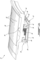
Fig. 2A is a perspective view of a turbine shroud assembly in accordance with an embodiment of the present disclosure; -
Fig. 2B is a schematic cross-section of the turbine shroud assembly ofFig. 2A mounted radially outwardly in close proximity to the tip of a row of turbine blades of a turbine rotor; -
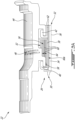
Fig. 3A is a raised side view of the turbine shroud segment assembly ofFig. 2A ; -
Fig. 3B is a schematic perspective cross-section of a machined turbine shroud segment green part, with a drilling tool and an air nozzle; -
Fig. 3C is a flowchart of a method of manufacturing a turbine shroud segment according to an embodiment of the present disclosure; -
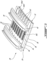
Fig. 4 is a perspective view of a turbine shroud segment according to an embodiment of the present disclosure; -
Fig. 5 is a perspective view of a turbine shroud segment according to another embodiment of the present disclosure; -
Fig. 6 is a perspective view of a turbine shroud segment according to another embodiment of the present disclosure; and -
Fig. 7A is a perspective view of a turbine shroud segment green part according to another embodiment of the present disclosure; -
Fig. 7B is a perspective of the turbine shroud segment green part ofFig. 7A , with a cutting tool; -
Fig. 7C is a perspective, closed-up view of a textured surface of the turbine shroud segment green part ofFig. 7A ; -
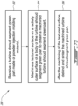
Fig. 7D is a flowchart of a method of manufacturing a turbine shroud segment according to another embodiment of the present disclosure; -
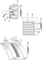
Figs. 8A and 8B are exploded, perspective views of a turbine shroud segment green part according to another embodiment of the present disclosure, with a schematic portion of a mold and a schematic portion of an injector for metal injection molding; -
Fig. 8C is a perspective view of the turbine shroud segment green part, schematic portion of a mold and schematic portion of an injector ofFigs. 8A and 8B ; -
Fig. 8D is a cross-section view of the turbine shroud segment green part, schematic portion of a mold and schematic portion of an injector ofFig. 8C ; -
Fig. 8E is a perspective, closed-up view of a textured surface of the turbine shroud segment green part ofFigs. 8A and 8B ; and -
Fig. 8F is a flowchart of a method of manufacturing a turbine shroud segment according to another embodiment of the present disclosure. - In this description and the appended claims, the singular forms "a," "an," and "the" are intended to include the plural forms as well, unless the context clearly indicates otherwise.
-
Fig. 1 illustrates agas turbine engine 10 of a type preferably provided for use in subsonic flight, generally comprising anannular gas path 11 disposed about an engine axisL. A fan 12, acompressor 14, acombustor 16 and aturbine 18 are axially spaced in serial flow communication along thegas path 11. More particularly, theengine 10 comprises afan 12 through which ambient air is propelled, acompressor section 14 for pressurizing the air, acombustor 16 in which the compressed air is mixed with fuel and ignited for generating an annular stream of hot combustion gases, and aturbine 18 for extracting energy from the combustion gases. - As shown in
Figs. 1 and2B , theturbine 18 includesturbine blades 20 mounted for rotation about the engine axis L. Aturbine shroud assembly 22 extends circumferentially about therotating blades 20. Theshroud assembly 22 is disposed in close radial proximity to thetips 28 of theblades 20 and defines therewith a blade tip clearance 24 (Fig. 2B ). Theshroud assembly 22 includes a plurality of arcuateturbine shroud segments 26 spaced circumferentially to provide an outer flow boundary surface of thegas path 11 around theblade tips 28. - In the embodiment shown in
Figs. 2A and2B , eachturbine shroud segment 26 has a body extending axially from a leadingedge 30 to a trailingedge 32 and circumferentially between opposed axially extending sides or lateral edges 34. In the present disclosure, the terms "front" and "frontward" refer to a direction approaching the leadingedge 30, while the terms "rear" and "rearward" refer to a direction approaching the trailingedge 32. The body has a radiallyinner surface 36 providing the outer flow boundary surface of thegas path 11 around theblade tip 28 and a radiallyouter surface 38 relative to the engine axis L. Front andrear support legs 40, 42 (e.g. hooks) extend from the radiallyouter surface 38 to hold theshroud segment 26 into a surrounding fixedstructure 44 of theengine 10, illustratively a casing for theshroud segment 26. As shown inFig. 2B , thecasing 44 includes impingement holes 46 for directing a flow of coolant C towards the radiallyouter surface 38 of the shroud, as will be discussed in further detail below. An optionaltop plate 48 may be affixed or otherwise installed above thecasing 44, thetop plate 48 including one or more additional impingement holes 50 for providing cooling to thecasing 44. - According to some embodiments, each
shroud segment 26 has a cooling scheme directing a flow of coolant C across the radiallyouter surface 38 and through the body of theshroud segment 26 from a front or upstream end portion of the body of theshroud segment 26 to a rear or downstream end portion thereof, as will be discussed in further detail below. This may allow to take full benefit of the pressure delta between the leading edge 30 (the front end) and the trailing edge 32 (the rear end). Acooling plenum 52 is defined between the front andrear support legs casing 44 supporting theshroud segments 26. Thecooling plenum 52 is connected in fluid flow communication to a source of the flow of coolant C. The coolant can be provided from any suitable source but is typically provided in the form of bleed air from one of the compressor stages. If thetop plate 48 is present, anadditional cooling plenum 54 may be defined between thetop plate 48 and thecasing 44, directing the flow of coolant C towards the impingement hole(s) 46 and providing a certain degree of cooling to thecasing 44 if desired. - The flow of coolant C exiting the impingement hole(s) 46 is directed or impinged onto a
textured surface 56 on the radiallyouter surface 38. As will be discussed in further detail below, thetextured surface 56 may promote heat transfer between the flow of coolant C and theshroud segment 26, for instance by increasing the wetted surface area of the radiallyouter surface 38 and/or by increasing the turbulence in the flow of coolant C. Various angles for the impingement hole(s) may be considered, for instance based on the desired level of cooling for theshroud segment 26. In the embodiment shown inFig. 2B , the impingement holes 46 direct the flow of coolant C in a radially inward direction towards thetextured surface 56, while in the embodiment shown inFig. 3A , the impingement holes 46 are angled towards the trailingedge 32 of the body of theshroud segment 26, thereby providing a rearward axial component. Other angles for the impingement hole(s) 46 may be contemplated as well. In various cases, the impingement holes 46 may be staggered axially along thecasing 44 with respect to the engine axis L, distributing the impingement holes 46 along thecasing 44 and thus improving the heat transfer between the flow of coolant C and thetextured surface 56. Other positioning arrangements for the impingement holes 46 may be contemplated as well. As will be discussed in further detail below, thetextured surface 56 may include peaks and valleys and/or turbulators to promote heat transfer between theshroud segment 26 and the flow of coolant C by increasing the wetted surface area and/or increasing the generated turbulence of the flow of coolant. - The cooling scheme further includes a plurality of cooling
inlets 58 for directing the flow of coolant C from thecooling plenum 52 into a front or upstream end of the body of theshroud segment 26 after the coolant C has interacted with thetextured surface 56, as will be discussed in further detail below. According to the illustrated embodiment, although not necessarily the case in all embodiments, the coolinginlets 58 are provided as a transverse row of inlet passages along thefront support leg 40. The coolinginlets 58 then direct the flow of coolant C through a cooling flow passageway, illustratively a plurality of axialcooling flow passageways 60, passing through the body of theshroud segment 26. Illustratively, the coolinginlets 58 include inlet ends opening on thecooling plenum 52 just downstream (rearwardly) of thefront support leg 40 and an outlet end opening to the cooling flow passageway underneath thefront support leg 40, as will be discussed in further detail below. As can be appreciated fromFig. 2B , each coolinginlet 58 may be angled to receive the flow of coolant C from thecooling plenum 52. The angle of inclination of the coolinginlets 58 may be an acute angle as measured from the radiallyouter surface 38 of theshroud segment 26 and oriented to direct the coolant toward the leadingedge 30 of theshroud segment 26. According to the illustrated embodiment, theinlets 58 are angled at about 45 degrees from the radiallyouter surface 38 of theshroud segment 26, although other angles may be contemplated as well. In various cases, the acute angling ofinlets 58 may direct the flow of coolant C towards the leadingedge 30 within the body of theshroud segment 26, which may additionally promote heat transfer between the flow of coolant C and theshroud segment 26. As the combined cross-sectional area of theinlets 58 is small relative to that of theplenum 52, the coolant may be conveniently accelerated as it is fed into the cooling flow passageway. The momentum gained by the coolant as it flows through the inlet passages may contribute to proving enhanced cooling at the front end portion of theshroud segment 26. - As shown in
Fig. 3A , the axialcooling flow passageways 60 are illustratively parallel cylindrical passageways. Other shapes for theaxial passageways 60 may be contemplated as well. As discussed above, theaxial passageways 60 begin at the coolinginlets 58 and follow a length of the body of theshroud segment 26 towards the trailingedge 32. In other words, theaxial passageways 60 have aportion 60a thereof extending along a direction having a component in an axial direction relative to the engine axis L when theturbine shroud segment 26 is mounted to thegas turbine engine 10. In some implementations, a ratio of a length of theportion 60a theaxial passageways 60 in the direction having a component in the axial direction relative to the engine axis L over the diameter of the axial passageway is greater than five, and in some implementations, greater than ten. In various embodiments, theaxial passageways 60 may promote heat transfer between theshroud segment 26, in particular from the radiallyinner surface 36, and the flow of coolant C. The number and dimensions of theaxial passageways 60 may vary according to the cooling requirements of theshroud segment 26 and the overall dimensions of theshroud segment 26. For instance, a greater number ofaxial passageways 60 may be required to accommodate a greater flow of coolant C, while the diameter of the illustratively cylindricalaxial passageways 60 may be limited by the overall thickness of the body of theshroud segment 26. - The cooling scheme further comprises a plurality of cooling
outlets 62 for discharging coolant from theaxial passageways 60. As shown inFig. 2A , the plurality ofoutlets 62 may include a row of outlet passages distributed along the trailingedge 32 of theshroud segment 26. The coolingoutlets 62 are sized to meter the flow of coolant discharged through the trailingedge 32 of theshroud segment 26. In the shown embodiment, the number ofcooling inlets 58 and the number ofcooling outlets 62 each correspond with the number ofaxial passageways 60. In some cases, theaxial passageways 60 may outnumber the coolinginlets 58 and cooling outlets 62 (or vice-versa), for instance if theaxial passageways 60 were to converge or diverge towards theinlets 58 oroutlets 62. - Referring now to
Figs. 3B and3C , amethod 100 of manufacturing theturbine shroud segment 26 will be described. Atstep 102, a turbine shroud segmentgreen part 26a is received. The turbine shroud segmentgreen part 26a is formed using metal injection molding (MIM) techniques. As is typical in MIM, a feedstock is injected into a mold cavity to obtain a green part, also referred to herein as "green body". The feedstock can include high temperature resistant powder metal alloys, such as a nickel superalloy. Other high temperature resistant material powders which may include one material or a mix of materials could be used as well. The feedstock is a mixture of the material powder and of a binder which may include one or more binding material(s). In a particular implementation, the binder includes an organic material which is molten above room temperature (20°C) but solid or substantially solid at room temperature. The binder may include various components such as surfactants which are known to assist the injection of the feedstock into the mold for production of the green part. In a particular implementation, the binder includes a mixture of binding materials, for example including a lower melting temperature polymer, such as a polymer having a melting temperature below 100°C (e.g. paraffin wax, polyethylene glycol, microcrystalline wax) and a higher melting temperature polymer or polymers, such as a polymer or polymers having a melting temperature above 100°C (e.g. polypropylene, polyethylene, polystyrene, polyvinyl chloride). Different combinations are also possible. In a particular implementation, the material powder is mixed with the molten binder and the suspension of injection powder and binder is injected into the mold cavity and cooled to a temperature below that of the melting point of the binder. "Green state", "green part" or "green body" as discussed herein refers to a molded part produced by the solidified binder that holds the injection powder together. - At
step 104, themethod 100 involves machining each of the axialcooling flow passageway 60 in the turbine shroud segmentgreen part 26a to obtain a machined turbine shroud segment green part. Since the feedstock is wax and/or polymer based, machining the green part can be performed with cutting feeds and speeds that are higher and cutting forces that are lower than typical feeds, speeds and forces for the machining of solid metal (for example the same metal as that found in powder form in the green body), and even when compared with "soft" metals such as aluminum. In a particular implementation, a machine tool that is designed for machining wax and plastics (e.g. small desktop CNC milling machine) is used to machine the green part. In a particular implementation, the cutting feeds and speeds are similar to that used during the machining of wax. In a particular implementation, the metal powder present in the green part provides for an increased material conductivity when compared to the binder material alone, which may help dissipate heat that may be generated during machining. When in the green state, the green part has a surface hardness that is smaller than the surface hardness of the sintered part. - To perform the
machining step 104, the turbine shroud segment green part is clamped/held using suitable retaining fixture(s), and adrilling tool 164a is used to form the axialcooling flow passageways 60. In some embodiments, anair nozzle 164b is located adjacent thedrilling tool 164a, and is adapted to supply pressurized air to thedrilling tool 164a to blow feedstock chips out of thedrilling tool 164a when thedrilling tool 164a is withdrawn from thegreen part 26a. In some implementations, in order to form each one of the axialcooling flow passageways 60, thedrilling tool 164a uses peck drilling techniques to incrementally drill each of theaxial passageways 60 in a plurality of drilling cycles. In some implementations, during a drilling cycle of the plurality of drilling cycles, thedrilling tool 164a is plunged through the shroud segmentgreen part 26a to a distance corresponding to more than five times the diameter of the axialcooling flow passageway 60. In some implementations, thedrilling tool 164a is plunged through the shroud segmentgreen part 26a to a distance corresponding to more than ten times the diameter of the axialcooling flow passageway 60. In some implementations, between two drilling cycles of the plurality of drilling cycles, thedrilling tool 164a retracts completely out of the axialcooling flow passageway 60 being drilled. - When the
drilling tool 164a is retracted, i.e. between two drilling cycles of the plurality of drilling cycles, pressurized air supplied by theair nozzle 164b is blown in the axialcooling flow passageway 60 to remove chips of feedstock present in the axialcooling flow passageway 60. Using the pressurized air supplied by theair nozzle 164b to evacuate chips of feedstock from thedrilling tool 164a and from the axialcooling flow passageway 60 being drilled keeps thedrilling tool 164a and the turbine shroud segment green part cool duringstep 104. Such cooling also limits the amount of feedstock chips sticking to the turbine shroud segmentgreen part 26a duringstep 104. Furthermore, the pressurized air supplied by theair nozzle 164b evacuating chips of feedstock from thedrilling tool 164a and from the axialcooling flow passageway 60 being drilled limits fragilization and/or damages caused to the turbine shroud segmentgreen part 26a during the formation of theaxial passageways 60. In other words, because the turbine shroud segmentgreen part 26a is fragile and brittle, forming theaxial passageways 60 using the aforementioned peck drilling techniques and pressurized air blowing reduces the fragilization and/or damages caused to the turbine shroud segmentgreen part 26a during the formation of theaxial passageways 60. - At
step 106, themethod 100 involves, afterstep 104, debinding and sintering the machined shroud segmentgreen part 26a. The debinding andsintering step 106 involves heating the machined shroud segmentgreen part 26a to a sintering temperature that is below the melting point of the material particles present in the feedstock, which results in metallurgical bonding of the material particles through cohesion and densification. After the debinding andsintering step 106, the machined shroud segmentgreen part 26a is then considered a sintered part. - Referring to
Fig. 4 , thetextured surface 56 on the radiallyouter surface 38 of theshroud segment 26 may include a series of alternating parallel peaks 56A1 and valleys 56A2, thus increasing the wetted surface area of the radiallyouter surface 38 with reference to a comparable shroud segment having a substantially smooth radiallyouter surface 38. As the flow of coolant C is impinged onto the radiallyouter surface 38, the peaks 56A1 and valleys 56A2 provide an increased wetted surface area for the flow of coolant C, thus promoting heat transfer between the radiallyouter surface 38 and the flow of coolant C. The peaks 56A1 and valleys 56A2 may further aid in moderating the operating conditions while cooling theshroud segment 26. The valleys 56A2 correspond to recessed portions of the radiallyouter surface 38, while the peaks 56A1 correspond to raised portions separating the valleys 56A2. As such, the formation of the valleys 56A2, for instance by removing material from the radiallyouter surface 38, may contribute to an overall weight reduction for theshroud segment 26. As shown inFig. 4 , the positioning of the valleys 56A2 may correspond to the locations of theaxial passageways 60 through the body of theshroud segment 26. As such, the peaks 56A1 and valleys 56A2 may be parallel to theaxial passageways 60 and thus may follow a direction from the leadingedge 30 to the trailingedge 32, illustratively beginning rearward of the coolinginlets 58 and terminating in front of therear support leg 42, with optional additional peaks 56A1 and valleys 56A2 beginning rearward of therear support leg 42 and terminating at the trailingedge 32. The number and width of the peaks 56A1 may depend on the number and sizing of the correspondingaxial passageways 60, although in other cases additional peaks 56A1 may be formed between the peaks 56A1 corresponding to theaxial passageways 60. Similarly, the number and width of the valleys 56A2 may depend on the number and spacing between adjacent peaks 56A1. The depth of the valleys 56A2 may vary as a function of the desired surface area increase of the radiallyouter surface 38 while ensuring the body of theshroud segment 26 maintains a minimum thickness to ensure its structural integrity. - As the flow of coolant C is impinged onto the radially
outer surface 38 in a direction towards the coolinginlets 58, the increase in surface area provided by the peaks 56A1 and valleys 56A2 increases the rate of heat transfer between the radiallyouter surface 38 and the flow of coolant C, thus improving the overall cooling effect on theshroud segment 26. Referring additionally toFig. 3A , to further improve cooling performance, a ratio between thedistance 64 between the outlets of the impingement hole(s) 46 and the radiallyouter surface 38 and the diameter of the impingement hole(s) 46 may be optimized. For instance, such a distance-to-diameter ratio may vary between 3 and 8 for optimal impingement performance, although other ratios may be contemplated as well. In addition, in various embodiments, the impingement hole(s) 46 may be positioned in thecasing 44 and angled so that the flow of coolant C is impinged towards locations on the radiallyouter surface 38 that are known to be "hot spots", i.e. locations that may require a more direct flow of coolant C to attain a desired level of cooling. - In various embodiments, the
textured surface 56 may further include a plurality of turbulators to further promote heat transfer between the radiallyouter surface 38 and the flow of coolant C, i.e. to improve cooling of theshroud segment 26. Such turbulators may include raised portions on theouter surface 38 to increase turbulence in the flow of coolant C and/or increase the wetted surface area of theouter surface 38. - Referring to
Fig. 5 , the turbulators may further or alternatively include a plurality of stand-offs 56C or pins. The term "stand-offs" used herein refers to a plurality of protrusions emanating from a surface, in this case the radiallyouter surface 38, to create turbulence in the flow of coolant C. The stand-offs 56C may additionally increase the wetted surface area of the radiallyouter surface 38, further promoting heat transfer between the radiallyouter surface 38 and the flow of coolant C. Illustratively, the stand-offs 56C are disposed within valleys 56A2 in a staggered formation, alternating between two and three stand-offs 56C per row. However, other arrangements may be contemplated as well. For instance, a greater number of stand-offs 56C may be arranged side-by-side if the corresponding valleys 56A2 were wider than the shown valleys 56A2. Additionally or alternatively, the sizing of the stand-offs 56C and the spacing between adjacent stand-offs 56C may be altered to increase or decrease the overall number of stand-offs. The number of stand-offs 56C may vary due to, for instance, the desired gains in generated turbulence and/or wetted surface area and various manufacturing constraints. The height of the stand-offs 56C may vary as well, for instance based on the depth of the valleys 56A2 and/or the desired level of generated turbulence. In some cases, the sizing of the stand-offs 56C may vary from one standoff to another. As the flow of coolant C is impinged onto the radiallyouter surface 38, the peaks 56A1 and valleys 56A2 provide an increased wetted surface area for the flow of coolant C while the stand-offs 56C create turbulence in the flow of coolant C, thus promoting heat transfer between the radiallyouter surface 38 and the flow of coolant C. Other types and/or shapes of turbulators may be considered as well. While the sections of the peaks 56A1 and valleys 56A2 rearward of therear support leg 42 are not shown to include stand-offs 56C, in other cases, for instance if additional sources of cooling flow were provided to different sections of theshroud segment 26, stand-offs 56C may be added to these rearward peaks 56A1 and valleys 56A2 to enhance cooling at the rear end of theshroud segment 26. - In various embodiments, the
textured surface 56 on the radiallyouter surface 38 may include a plurality of turbulators without peaks and valleys. For instance, depending on the given cooling requirements of a specific application, the generation of turbulence, for instance via crosses and/or stand-offs, in the flow of coolant C may provide sufficient cooling to theshroud segment 26 without the need for the increased surface area provided by the peaks and valleys. Referring toFig. 6 , there is shown a plurality of turbulators, illustratively a plurality of stand-offs 56C, protruding from an optional recessedportion 66 of the radiallyouter surface 38 to generate turbulence in the flow of coolant C to promote heat transfer between the radiallyouter surface 38 and the flow of coolant C. In various cases, the optional recessedportion 66 may reduce the overall weight of theshroud segment 26 due to the removed material from the radiallyouter surface 38, and its depth may vary, for instance, based on the desired weight of theshroud segment 26, the desired height of the turbulators disposed within, and the sizing of theaxial passageways 60 disposed within the body of theshroud segment 26. In other cases, the turbulators may be disposed directly on the radiallyouter surface 38 in the absence of the recessedportion 66. In other cases, the turbulators may include crosses 56B or a combination of crosses 56B and stand-offs 56C. Other protruding turbulator shapes may be considered as well. - Various embodiments of the above-described cooling schemes thus provide for a flow of coolant C being impinged by one or more impingement holes 46 in a
structure 44 of theengine 10 onto atextured surface 56 on the radiallyouter surface 38 of theshroud segment 26. Suchtextured surface 56 may include peaks 56A1 and valleys 56A2 and/or turbulators such as crosses 56B or stand-offs 56C to promote heat transfer by increasing the wetted surface area of the radiallyouter surface 38 and/or generating turbulence in the flow of coolant C. The flow of coolant C is then directed through coolinginlets 58 throughaxial passageways 60 within the body of theshroud segment 26 to provide additional cooling to theshroud segment 26 before exiting via a transverse row ofoutlets 62 provided at the trailingedge 32 of theshroud segment 26. - In this way, in various embodiments, the flow of coolant C may effectively and uniformly cool the
entire shroud segment 26 via heat transfer at the radiallyouter surface 38 and within the body of theshroud segment 26. In various embodiments, the above-describedshroud segments 26 may increase the overall efficiency of thegas turbine engine 10 by, for instance, reducing weight and providing additional cooling. In addition, the lifespan of theshroud segment 26 may be increased due to the increased cooling capacity. Further, in various embodiments, the improved cooling efficiency provided by the various cooling schemes may reduce the quantity of coolant flow required to achieve the desired level of cooling of theshroud segment 26. In addition, in various embodiments thegas turbine engine 10 may be able to operate with a higher gas path temperature due to the improved cooling efficiency capabilities. - Referring to now
Figs. 7A to 7D , a method 200 of manufacturing aturbine shroud segment 26 will be described. Atstep 202, a turbine shroud segmentgreen part 26a is received. The turbine shroud segmentgreen part 26a is formed using metal injection molding (MIM) techniques. The turbine shroud segmentgreen part 26a is similar to the turbine shroud segmentgreen part 26a described with reference to step 102 of themethod 100 described above. - At
step 204, thetextured surface 56 is machined on the radiallyouter surface 38 to obtain a machined turbine shroud segment green part. To perform themachining step 204, the turbine shroud segment green part is clamped/held using suitable retaining fixture(s), and acutting tool 264a is used to form the features of thetextured surface 56, i.e. one or more of the recessedportion 66, peaks 56A1, valleys 56A2, crosses 56B and stand-offs 56C. In the present implementation, thecutting tool 264a is a short and small endmill adapted to cut the turbine shroud segmentgreen part 26a to define the features of thetextured surface 56. For example, thecutting tool 264a is adapted to define each of the turbulators individually. Referring toFig. 7C , the turbulators are stand-offs 56C. Each of the stand-offs 56C is individually defined by thecutting tool 264a. Each one of the stand-offs 56C has a cylindrical shape, and a rounded portion 56D extending between the recessedportion 66 and the cylindrically shaped portion of the stand-off 56C. Other shapes and configurations for the stand-offs 56C may be considered in other implementations. - Referring to
Fig. 7B , in some embodiments, duringstep 204, anair nozzle 264b is located adjacent thecutting tool 264a, and is adapted to supply pressurized air to thecutting tool 264a to blow feedstock chips away from thecutting tool 264a. Using the pressurized air supplied by theair nozzle 264b to evacuate chips of feedstock from thecutting tool 264a and the feature of thetextured surface 56 being formed keeps thecutting tool 264a and the turbine shroud segmentgreen part 26a cool duringstep 204. Such cooling also limits the amount of feedstock chips sticking to the turbine shroud segmentgreen part 26a duringstep 204. Furthermore, the pressurized air supplied by theair nozzle 264b evacuating chips of feedstock from thecutting tool 264a limits fragilization and/or damages caused to the turbine shroud segmentgreen part 26a during the formation of the features of thetextured surface 56. In other words, because the turbine shroud segmentgreen part 26a is fragile and brittle, forming the features of thetextured surface 56 using the aforementioned pressurized air reduces the fragilization and/or damages caused to the turbine shroud segmentgreen part 26a during the formation of thetextured surface 56. - At
step 206, the method 200 involves debinding and sintering the machined shroud segmentgreen part 26a. The debinding andsintering step 206 involves heating the machined shroud segmentgreen part 26a to a sintering temperature that is below the melting point of the material particles present in the feedstock, which results in metallurgical bonding of the material particles through cohesion and densification. After the debinding andsintering step 206, the machined shroud segmentgreen part 26a is then considered a sintered part. - Referring now to
Figs. 8A to 8F , a method 300 of manufacturing aturbine shroud segment 26 will be described. Atstep 302, powder injection molding material is injected by aninjector 302a into amold 302b for forming a metal injection molded turbine shroud segmentgreen part 26a. As best seen inFig. 8B , themold 302b hascavities 302c defining negatives of the features forming thetextured surface 56 on the radiallyouter surface 38 of the body of the turbine shroud segmentgreen part 26a. Themold 302b also defines the recessedportion 66. In some implementations, themold 302b has other cavities defining the negative of one or more of the recessedportion 66, peaks 56A1, valleys 56A2, crosses 56B and stand-offs 56C. In the present implementation and as best seen inFig. 8E , the stand-offs 56C have a frustoconical shape to allow for unmolding. Step 302 is performed using low pressure MIM to ensure that the feedstock fills thecavities 302c of themold 302b. Mold temperature is also controlled duringstep 302. If too hot, the feedstock will stick. If too cold, the feedstock will not fill thecavities 302c properly. Duringstep 302, in order to properly fill thecavities 302c with the feedstock for forming thetextured surface 56, air is evacuated from within themold 302b via avent 302d (Fig. 8D ) defined in themold 302b. Thevent 302d is fluidly connected to thecavities 302c of themold 302b defining the turbulators, and air that would otherwise be trapped between themold 302b and the feedstock being injected is evacuated through thevent 302d. As best seen inFig. 8D , thevent 302d extends axially betweenadjacent support legs green part 26a, theadjacent support legs outer surface 38 of the turbine shroud segmentgreen part 26a. Thevent 302d also extends radially outward from the radiallyouter surface 38 of the turbine shroud segmentgreen part 26a. - At
step 304, the method 300 involves debinding and sintering the molded turbine shroud segmentgreen part 26a. The debinding andsintering step 304 involves heating the turbine shroud segmentgreen part 26a to a sintering temperature that is below the melting point of the material particles present in the feedstock, which results in metallurgical bonding of the material particles through cohesion and densification. After the debinding andsintering step 304, the turbine shroud segmentgreen part 26a is then considered a sintered part. - Using any one of, or a combination of, the
methods 100, 200, 300 offer an alternative to manufacturing the turbine shroud segments using casting or machined parts. More particularly, themethods 100, 200, 300 allow for the formation of cooling features onturbine shroud segments 26 in a cost effective manner compared to other manufacturing methods. - The embodiments described in this document provide non-limiting examples of possible implementations of the present technology. Upon review of the present disclosure, a person of ordinary skill in the art will recognize that changes may be made to the embodiments described herein without departing from the scope of the present technology. Yet further modifications could be implemented by a person of ordinary skill in the art in view of the present disclosure, which modifications would be within the scope of the present technology.
Claims (15)
- A method of manufacturing a turbine shroud segment (26) for a gas turbine engine (10) defining an engine axis (L), the method comprising the steps of:receiving a turbine shroud segment green part (26a) made of powder injection molding material;machining an axial cooling flow passageway (60) in the turbine shroud segment green part (26a) to obtain a machined turbine shroud segment green part (26a), the axial cooling flow passageway (60) extending along a direction having a component in an axial direction relative to the engine axis (L) when the turbine shroud segment (26) is mounted to the gas turbine engine (10); andafter the machining of the axial cooling flow passageway (60), debinding and sintering the machined turbine shroud segment green part (26a).
- The method of claim 1, wherein the machining the axial cooling flow passageway (60) comprises peck drilling the axial cooling flow passageway (60) with a drilling tool (164a) in a plurality of drilling cycles.
- The method of claim 2, wherein the axial cooling flow passageway (60) has a diameter, and the peck drilling comprises, during a drilling cycle of the plurality of drilling cycles, plunging the drilling tool (164a) through the turbine shroud segment green part (26a) to a distance corresponding to more than five times the diameter of the axial cooling flow passageway (60).
- The method of claim 2 or 3, wherein the machining comprises blowing pressurized air on the drilling tool (164a) between two drilling cycles of the plurality of drilling cycles.
- The method of claim 2, 3 or 4, wherein the machining comprises blowing pressurized air in the axial cooling flow passageway (60) between two drilling cycles of the plurality of drilling cycles.
- The method of any one of claims 2 to 5, wherein, between two drilling cycles of the plurality of drilling cycles, the drilling tool (164a) retracts completely out of the axial cooling flow passageway (60).
- The method of any one of claims 1 to 6 wherein the turbine shroud segment green part (26a) includes a body extending axially between a leading edge (30) and a trailing edge (32) and circumferentially between a first lateral edge (34) and a second lateral edge (34), the body having a radially outer surface (38) and a radially inner surface (36);
and wherein prior to debinding and sintering, the method further comprises machining a textured surface (56) on the radially outer surface (38) of the body. - The method of claim 7, wherein the machining the textured surface (56) comprises forming a recessed portion (66) on the radially outer surface (38).
- The method of claim 8, wherein the machining further comprises forming a plurality of turbulators (56C) protruding from the recessed portion (66) on the radially outer surface (38), optionally wherein the machining the textured surface (56) comprises forming each turbulator (56C) of the plurality of turbulators (56C) individually with a cutting tool (246a), and optionally blowing pressurized air on at least one of the cutting tool (246a) and the turbulator (56C) being formed by the cutting tool (246a).
- The method of any one of claims 1 to 6, further comprising:
injecting powder injection molding material into a mold (302b) for forming the turbine shroud segment green part (26a), the turbine shroud segment green part (26a) including a body extending axially between a leading edge (30) and a trailing edge (32) and circumferentially between a first lateral edge (34) and a second lateral edge (34), the body having a radially outer surface (38) and a radially inner surface (36), the mold (302b) having cavities (302c) defining negatives of features forming a textured surface (56) on the radially outer surface (38) of the body. - The method of claim 10, wherein the textured surface (56) comprises a recessed portion (66) on the radially outer surface (38) and optionally a plurality of turbulators (56C) protruding from the recessed portion (66) on the radially outer surface (38), and wherein the plurality of turbulators (56C) optionally includes stand-offs (56C) having a frustoconical shape.
- The method of claim 11, wherein, during the injecting of the powder injection molding material into the mold (302b), air is evacuated from within the mold (302b) via a vent (302d) defined in the mold (302b).
- The method of claim 12, wherein, during the injecting of the powder injection molding material into the mold (302b), the vent (302d) is fluidly connected to the cavities (302c) of the mold (302d) defining the plurality of turbulators (56C).
- The method of claim 12 or 13, wherein the vent (302d) extends axially between adjacent support legs (40, 42) of the turbine shroud segment green part (26a), the adjacent support legs (40, 42) extending radially outward from the radially outer surface (38) of the turbine shroud segment green part (26a).
- The method of claim 14, wherein the vent (302d) further extends radially outward from the radially outer surface (38) of the turbine shroud segment green part (26a).
Applications Claiming Priority (1)
| Application Number | Priority Date | Filing Date | Title |
|---|---|---|---|
| US18/541,518 US12479055B2 (en) | 2023-12-15 | 2023-12-15 | Method of manufacturing a turbine shroud segment |
Publications (1)
| Publication Number | Publication Date |
|---|---|
| EP4574309A1 true EP4574309A1 (en) | 2025-06-25 |
Family
ID=93924350
Family Applications (1)
| Application Number | Title | Priority Date | Filing Date |
|---|---|---|---|
| EP24220358.6A Pending EP4574309A1 (en) | 2023-12-15 | 2024-12-16 | Method of manufacturing a turbine shroud segment |
Country Status (2)
| Country | Link |
|---|---|
| US (1) | US12479055B2 (en) |
| EP (1) | EP4574309A1 (en) |
Citations (3)
| Publication number | Priority date | Publication date | Assignee | Title |
|---|---|---|---|---|
| EP2985098A2 (en) * | 2014-07-23 | 2016-02-17 | Pratt & Whitney Canada Corp. | Method of manufacturing gas turbine engine element having at least one elongated opening |
| US20180272562A1 (en) * | 2014-07-21 | 2018-09-27 | Pratt & Whitney Canada Corp. | Method of forming green part and manufacturing method using same |
| EP3981955A1 (en) * | 2020-10-07 | 2022-04-13 | Pratt & Whitney Canada Corp. | Turbine shroud cooling |
Family Cites Families (3)
| Publication number | Priority date | Publication date | Assignee | Title |
|---|---|---|---|---|
| US9970318B2 (en) | 2014-06-25 | 2018-05-15 | Pratt & Whitney Canada Corp. | Shroud segment and method of manufacturing |
| US20160263656A1 (en) | 2015-03-12 | 2016-09-15 | Pratt & Whitney Canada Corp. | Method of forming a component from a green part |
| US11919082B2 (en) | 2021-10-28 | 2024-03-05 | Rolls-Royce Corporation | Method for making turbine engine components using metal injection molding |
-
2023
- 2023-12-15 US US18/541,518 patent/US12479055B2/en active Active
-
2024
- 2024-12-16 EP EP24220358.6A patent/EP4574309A1/en active Pending
Patent Citations (3)
| Publication number | Priority date | Publication date | Assignee | Title |
|---|---|---|---|---|
| US20180272562A1 (en) * | 2014-07-21 | 2018-09-27 | Pratt & Whitney Canada Corp. | Method of forming green part and manufacturing method using same |
| EP2985098A2 (en) * | 2014-07-23 | 2016-02-17 | Pratt & Whitney Canada Corp. | Method of manufacturing gas turbine engine element having at least one elongated opening |
| EP3981955A1 (en) * | 2020-10-07 | 2022-04-13 | Pratt & Whitney Canada Corp. | Turbine shroud cooling |
Also Published As
| Publication number | Publication date |
|---|---|
| US12479055B2 (en) | 2025-11-25 |
| US20250196274A1 (en) | 2025-06-19 |
Similar Documents
| Publication | Publication Date | Title |
|---|---|---|
| US20240102392A1 (en) | Component for a turbine engine with a cooling hole | |
| US10570750B2 (en) | Turbine component with tip rail cooling passage | |
| US10436039B2 (en) | Gas turbine engine turbine blade tip cooling | |
| US20190085705A1 (en) | Component for a turbine engine with a film-hole | |
| EP2497905B1 (en) | Turbine bucket for use in gas turbine engines and methods for fabricating the same | |
| US11220918B2 (en) | Gas turbine component with cooling aperture having shaped inlet and method of forming the same | |
| EP2847435B1 (en) | Convective heat removal cooling hole pattern | |
| US11927110B2 (en) | Component for a turbine engine with a cooling hole | |
| EP3483392B1 (en) | Gas turbine engines with improved airfoil dust removal | |
| EP2944763A2 (en) | Hot gas path component | |
| CN111255524A (en) | Turbine bucket tip cooling system including tip rail cooling insert | |
| EP4180626B1 (en) | A turbomachine blade, a coupon for replacing a cutout in an airfoil body and a gas turbine system | |
| JP2004028097A (en) | Apparatus and method for cooling turbine blade wall | |
| EP3981955A1 (en) | Turbine shroud cooling | |
| US10408065B2 (en) | Turbine component with rail coolant directing chamber | |
| US12479055B2 (en) | Method of manufacturing a turbine shroud segment | |
| US11458541B2 (en) | Method of manufacturing a component | |
| US11572801B2 (en) | Turbine engine component with baffle | |
| US11486259B1 (en) | Component with cooling passage for a turbine engine | |
| EP3260658B1 (en) | Trailing edge ejection cooling of an aerofoil | |
| CN117627732A (en) | turbine engine airfoils |
Legal Events
| Date | Code | Title | Description |
|---|---|---|---|
| PUAI | Public reference made under article 153(3) epc to a published international application that has entered the european phase |
Free format text: ORIGINAL CODE: 0009012 |
|
| STAA | Information on the status of an ep patent application or granted ep patent |
Free format text: STATUS: THE APPLICATION HAS BEEN PUBLISHED |
|
| AK | Designated contracting states |
Kind code of ref document: A1 Designated state(s): AL AT BE BG CH CY CZ DE DK EE ES FI FR GB GR HR HU IE IS IT LI LT LU LV MC ME MK MT NL NO PL PT RO RS SE SI SK SM TR |
|
| STAA | Information on the status of an ep patent application or granted ep patent |
Free format text: STATUS: REQUEST FOR EXAMINATION WAS MADE |
|
| 17P | Request for examination filed |
Effective date: 20251208 |