EP4574307A1 - Method to requalify die after storage - Google Patents
Method to requalify die after storage Download PDFInfo
- Publication number
- EP4574307A1 EP4574307A1 EP24218872.0A EP24218872A EP4574307A1 EP 4574307 A1 EP4574307 A1 EP 4574307A1 EP 24218872 A EP24218872 A EP 24218872A EP 4574307 A1 EP4574307 A1 EP 4574307A1
- Authority
- EP
- European Patent Office
- Prior art keywords
- die
- storage
- scan
- production
- time
- Prior art date
- Legal status (The legal status is an assumption and is not a legal conclusion. Google has not performed a legal analysis and makes no representation as to the accuracy of the status listed.)
- Granted
Links
Images


Classifications
-
- B—PERFORMING OPERATIONS; TRANSPORTING
- B22—CASTING; POWDER METALLURGY
- B22D—CASTING OF METALS; CASTING OF OTHER SUBSTANCES BY THE SAME PROCESSES OR DEVICES
- B22D46/00—Controlling, supervising, not restricted to casting covered by a single main group, e.g. for safety reasons
-
- G—PHYSICS
- G01—MEASURING; TESTING
- G01B—MEASURING LENGTH, THICKNESS OR SIMILAR LINEAR DIMENSIONS; MEASURING ANGLES; MEASURING AREAS; MEASURING IRREGULARITIES OF SURFACES OR CONTOURS
- G01B11/00—Measuring arrangements characterised by the use of optical techniques
- G01B11/02—Measuring arrangements characterised by the use of optical techniques for measuring length, width or thickness
-
- B—PERFORMING OPERATIONS; TRANSPORTING
- B22—CASTING; POWDER METALLURGY
- B22C—FOUNDRY MOULDING
- B22C9/00—Moulds or cores; Moulding processes
-
- G—PHYSICS
- G01—MEASURING; TESTING
- G01B—MEASURING LENGTH, THICKNESS OR SIMILAR LINEAR DIMENSIONS; MEASURING ANGLES; MEASURING AREAS; MEASURING IRREGULARITIES OF SURFACES OR CONTOURS
- G01B11/00—Measuring arrangements characterised by the use of optical techniques
-
- G—PHYSICS
- G01—MEASURING; TESTING
- G01B—MEASURING LENGTH, THICKNESS OR SIMILAR LINEAR DIMENSIONS; MEASURING ANGLES; MEASURING AREAS; MEASURING IRREGULARITIES OF SURFACES OR CONTOURS
- G01B11/00—Measuring arrangements characterised by the use of optical techniques
- G01B11/02—Measuring arrangements characterised by the use of optical techniques for measuring length, width or thickness
- G01B11/06—Measuring arrangements characterised by the use of optical techniques for measuring length, width or thickness for measuring thickness ; e.g. of sheet material
-
- G—PHYSICS
- G01—MEASURING; TESTING
- G01B—MEASURING LENGTH, THICKNESS OR SIMILAR LINEAR DIMENSIONS; MEASURING ANGLES; MEASURING AREAS; MEASURING IRREGULARITIES OF SURFACES OR CONTOURS
- G01B9/00—Measuring instruments characterised by the use of optical techniques
-
- G—PHYSICS
- G01—MEASURING; TESTING
- G01M—TESTING STATIC OR DYNAMIC BALANCE OF MACHINES OR STRUCTURES; TESTING OF STRUCTURES OR APPARATUS, NOT OTHERWISE PROVIDED FOR
- G01M15/00—Testing of engines
- G01M15/14—Testing gas-turbine engines or jet-propulsion engines
-
- G—PHYSICS
- G06—COMPUTING OR CALCULATING; COUNTING
- G06T—IMAGE DATA PROCESSING OR GENERATION, IN GENERAL
- G06T17/00—Three-dimensional [3D] modelling for computer graphics
Definitions
- This application relates to bringing a previously utilized cast metal die out of storage, and requalifying it for production.
- Dies are utilized in number of applications.
- One type die is a metal cast die. In such a die metal is injected into a cavity, and forms a component.
- One common use of such dies is to form components having an airfoil such as turbine blades, static vanes, compressor blades, and compressor static vanes.
- the die In the prior art after manufacture, and before moving to production the die must be certified. Typically, the die is utilized to form a relatively large number of components to be inspected. As an example, there may be on the order of two dozen components made.
- the formed components are then subject to detailed inspection to ensure that they meet part requirements. It is only after the inspection of the produced components is passed that the die is moved towards production.
- the die may be taken out of production such as when sufficient parts have been produced.
- the entire qualification process must be repeated once the die is brought back into service.
- a method of requalifying a die after storage includes the steps of running production parts on a die, stopping production for a period of time, taking a pre-storage 3D scan of the die, storing the die for a period of time, taking a post storage 3D scan of the die, comparing the post storage 3D scan information to the pre-storage 3D scan information, and requalifying the die for use in production should the post storage 3D scan be found to be sufficiently close to the pre-storage 3D scan.
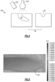
- Figure 1A shows a die 20 schematically. As known, a cavity 22 receives injected metal from a source 24.
- FIG. 1B One component which may be formed by such a die is shown in Figure 1B .
- a turbine blade 26 has an airfoil 25. While a turbine blade is specifically disclosed, it should be understood that other gas turbine engine components may be formed using metal cast dies such as the Figure 1A die.
- airfoils are complex structures, and have demanding dimensional challenges in forming the desired structure. For this reason, dies to form an airfoil are subject to intense qualification tests before being utilized to make production airfoils.
- the die is built, and then utilized to produce what is called a qualification lot. As an example, this may be on the order of two dozen components, or more. Those produced components are then inspected and compared to desired dimensions, etc. It is only after this inspection has been passed that the die would be moved toward production. In the prior art, this qualification was performed not only for an initial die, but for all subsequent dies made to be similar to an initial or master die.
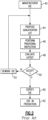
- Figure 2 shows existing method 38 for qualifying a die.
- a die may be designed and built.
- a qualification lot is produced at step 44.
- a traditional inspection is then performed on the qualification lot at step 46.
- the results, or the layout, are evaluated at step 48.
- step 50 a decision is made whether to accept the layout. If not, the die is reworked at step 52, and the flow chart returns downstream of step 40.
- the die is certified at step 60 and is used in production at step 62.
- the qualification of the die is a very time consuming process.
- the method of this disclosure will shorten the requalification purpose for a die which has been out of use and stored for a minimum period of time.
- dies must be recertified if they have been stored for greater than two years, as an example.
- At some point production may be stopped with a particular die at step 110.
- a 3D scan on the die is performed at step 112.
- structured light scanning techniques are utilized. Pictures should be taken showing the entire die from each side and a close up of any particular area of interest.
- FIG 4 schematically shows a simple system 100 for performing the 3D scans.
- a camera 102 takes photos of the interior of the cavity 22 as illuminated by a structured light scanning system 104.
- Other type scanning systems may be used.
- the die may then be stored at step 114. At some subsequent point a decision may be made to restart production of the part from the die at step 116.
- step 118 the die is taken out of storage.
- a post storage 3D scan of the die is performed at step 120.
- the post storage 3D scan will be done with the exact same angle, photos, etc. from the pre-storage die scan.
- the die Prior to the post storage 3D scan, the die is cleaned.
- the scanned information from the pre and post storages scans are compared to each other to requalify the die.
- a map 150 in Figure 5 shows that the tool has not changed, scale is on the right side of the image.
- the pre storage 3D scan is provided with the best fit overlay to the post storage 3D scan.
- the evidence which is looked at may be in the form of a simple product of the die thickness across both die halves and at each die cavity end. These inspections will determine the die functionality has not changed.
- the die is requalified after this step 122 then the die is used in production again at step 124.
- a method of requalifying a die after storage under this disclosure could be said to include the steps of running production parts on a die, stopping production for a period of time, taking a pre-storage 3D scan of the die, storing the die for a period of time, taking a post storage 3D scan of the die, comparing the post storage 3D scan information to the pre-storage 3D scan information, and requalifying the die for use in production should the post storage 3D scan be found to be sufficiently close to the pre-storage 3D scan.
- the die is used to form a component after being requalified.
- the component has an airfoil.
- the pre-storage and post storage 3D scans utilize structured light scanning.
- the minimum period of time is at least one year.
- the minimum period of time is at least two years.
- the die is a cast metal die, and the cavity receives a supply of molten metal when operating in production.
- the minimum period of time is at least one year.
Landscapes
- Engineering & Computer Science (AREA)
- Mechanical Engineering (AREA)
- Physics & Mathematics (AREA)
- General Physics & Mathematics (AREA)
- Powder Metallurgy (AREA)
- Moulds For Moulding Plastics Or The Like (AREA)
Abstract
Description
- This application relates to bringing a previously utilized cast metal die out of storage, and requalifying it for production.
- Dies are utilized in number of applications. One type die is a metal cast die. In such a die metal is injected into a cavity, and forms a component.
- One common use of such dies is to form components having an airfoil such as turbine blades, static vanes, compressor blades, and compressor static vanes.
- In the prior art after manufacture, and before moving to production the die must be certified. Typically, the die is utilized to form a relatively large number of components to be inspected. As an example, there may be on the order of two dozen components made.
- The formed components are then subject to detailed inspection to ensure that they meet part requirements. It is only after the inspection of the produced components is passed that the die is moved towards production.
- All of these steps put in place a long lead time between ordering a die, and having it ready for production.
- At some point the die may be taken out of production such as when sufficient parts have been produced. Currently, if a die is stored for more than a predetermined period of time the entire qualification process must be repeated once the die is brought back into service.
- A method of requalifying a die after storage includes the steps of running production parts on a die, stopping production for a period of time, taking a pre-storage 3D scan of the die, storing the die for a period of time, taking a
post storage 3D scan of the die, comparing thepost storage 3D scan information to the pre-storage 3D scan information, and requalifying the die for use in production should thepost storage 3D scan be found to be sufficiently close to the pre-storage 3D scan. - There is provided herein a method of requalifying a die after storage as recited in claim 1.
- Features of embodiments are set forth in the dependent claims.
- These and other features will be best understood from the following drawings and specification, the following is a brief description.
-
-
Figure 1A schematically shows a metal cast die performing a component. -
Figure 1B shows a gas turbine engine component which may be formed by a die such as theFigure 1A die. -
Figure 2 is a flow chart of a method for certifying a die initially. -
Figure 3 is a flow chart of a method for requalifying a die after storage. -
Figure 4 shows a scanning system. -
Figure 5 shows a map comparing two scans. -
Figure 1A shows a die 20 schematically. As known, acavity 22 receives injected metal from asource 24. - One component which may be formed by such a die is shown in
Figure 1B . Here aturbine blade 26 has anairfoil 25. While a turbine blade is specifically disclosed, it should be understood that other gas turbine engine components may be formed using metal cast dies such as theFigure 1A die. - As well known, airfoils are complex structures, and have demanding dimensional challenges in forming the desired structure. For this reason, dies to form an airfoil are subject to intense qualification tests before being utilized to make production airfoils.
- In the prior art, and before a die is utilized in production, it must first be certified.
- In one common method of certification, the die is built, and then utilized to produce what is called a qualification lot. As an example, this may be on the order of two dozen components, or more. Those produced components are then inspected and compared to desired dimensions, etc. It is only after this inspection has been passed that the die would be moved toward production. In the prior art, this qualification was performed not only for an initial die, but for all subsequent dies made to be similar to an initial or master die.
-
Figure 2 shows existing method 38 for qualifying a die. Atstep 40, a die may be designed and built. - A qualification lot is produced at
step 44. - A traditional inspection is then performed on the qualification lot at
step 46. The results, or the layout, are evaluated atstep 48. - At
step 50, a decision is made whether to accept the layout. If not, the die is reworked atstep 52, and the flow chart returns downstream ofstep 40. - If the layout is accepted at
step 50 then, the die is certified atstep 60 and is used in production atstep 62. - As mentioned above, the qualification of the die is a very time consuming process. The method of this disclosure will shorten the requalification purpose for a die which has been out of use and stored for a minimum period of time. Currently dies must be recertified if they have been stored for greater than two years, as an example.
- If the period of time is not greater than a minimum then the requalification steps need not be performed.
- Thus, as shown in
Figure 3 , at some point production may be stopped with a particular die atstep 110. At that point a 3D scan on the die is performed atstep 112. In one embodiment, structured light scanning techniques are utilized. Pictures should be taken showing the entire die from each side and a close up of any particular area of interest. -
Figure 4 schematically shows asimple system 100 for performing the 3D scans. As shown, acamera 102 takes photos of the interior of thecavity 22 as illuminated by a structuredlight scanning system 104. Other type scanning systems may be used. - The die may then be stored at
step 114. At some subsequent point a decision may be made to restart production of the part from the die atstep 116. - Assuming the die has been stored for a minimum period of time it will need to be requalified. In the prior art, the
Figure 2 method would be used. - At
step 118 the die is taken out of storage. Apost storage 3D scan of the die is performed atstep 120. Thepost storage 3D scan will be done with the exact same angle, photos, etc. from the pre-storage die scan. - Prior to the
post storage 3D scan, the die is cleaned. - At
step 122 the scanned information from the pre and post storages scans are compared to each other to requalify the die. A before and after 3D scan overlay comparison of the concave side of the tool. Amap 150 inFigure 5 shows that the tool has not changed, scale is on the right side of the image. - In one embodiment, the
pre storage 3D scan is provided with the best fit overlay to thepost storage 3D scan. The evidence which is looked at may be in the form of a simple product of the die thickness across both die halves and at each die cavity end. These inspections will determine the die functionality has not changed. - If the die is requalified after this
step 122 then the die is used in production again atstep 124. - A method of requalifying a die after storage under this disclosure could be said to include the steps of running production parts on a die, stopping production for a period of time, taking a pre-storage 3D scan of the die, storing the die for a period of time, taking a
post storage 3D scan of the die, comparing thepost storage 3D scan information to the pre-storage 3D scan information, and requalifying the die for use in production should thepost storage 3D scan be found to be sufficiently close to the pre-storage 3D scan. - In another embodiment according to the previous embodiment, the die is used to form a component after being requalified.
- In another embodiment according to any of the previous embodiments, the component has an airfoil.
- In another embodiment according to any of the previous embodiments, the pre-storage and post
storage 3D scans utilize structured light scanning. - In another embodiment according to any of the previous embodiments, if the period of time is not greater than a minimum then the post storage steps are not performed.
- In another embodiment according to any of the previous embodiments, prior to the
post storage 3D scan, the die is cleaned. - In another embodiment according to any of the previous embodiments, the minimum period of time is at least one year.
- In another embodiment according to any of the previous embodiments, the minimum period of time is at least two years.
- In another embodiment according to any of the previous embodiments, the die is a cast metal die, and the cavity receives a supply of molten metal when operating in production.
- In another embodiment according to any of the previous embodiments, the 3D scans of pre-storage and post storage utilize structured light scanning.
- In another embodiment according to any of the previous embodiments, if the period of time is not greater than a minimum then the post storage steps are not performed.
- In another embodiment according to any of the previous embodiments, prior to the
post storage 3D scan, the die is cleaned. - In another embodiment according to any of the previous embodiments, the minimum period of time is at least one year.
- In another embodiment according to any of the previous embodiments, the minimum period of time is at least two years.
- In another embodiment according to any of the previous embodiments, the die is a cast metal die, and the cavity receives a supply of molten metal when operating in production.
- In another embodiment according to any of the previous embodiments, if the period of time is not greater than a minimum then the post storage steps are not performed.
- In another embodiment according to any of the previous embodiments, the minimum period of time is at least one year.
- In another embodiment according to any of the previous embodiments, prior to the
post storage 3D scan, the die is cleaned. - In another embodiment according to any of the previous embodiments, prior to the
post storage 3D scan, the die is cleaned. - In another embodiment according to any of the previous embodiments, the die is a cast metal die, and the cavity receives a supply of molten metal when operating in production.
- Although embodiments have been disclosed, a worker of skill in this art would recognize that modifications would come within the scope of this disclosure. For that reason, the following claims should be studied to determine the true scope and content.
Claims (9)
- A method of requalifying a die (20) after storage comprising the steps of:running production parts on a die (20);stopping production for a period of time;taking a pre-storage 3D scan of the die (20);storing the die (20) for a period of time;taking a post storage 3D scan of the die (20);comparing the post storage 3D scan information to the pre-storage 3D scan information; andrequalifying the die (20) for use in production should the post storage 3D scan be found to be sufficiently close to the pre-storage 3D scan.
- The method as set forth in claim 1, wherein the die (20) is used to form a component (26) after requalification.
- The method as set forth in claim 2, wherein the component (26) has an airfoil (25).
- The method as set forth in any preceding claim, wherein the pre-storage and post storage 3D scans utilize structured light scanning.
- The method as set forth in any preceding claim, wherein if the period of time is not greater than a minimum then the post storage steps are not performed.
- The method as set forth in any preceding claim, wherein prior to the post storage 3D scan, the die (20) is cleaned.
- The method as set forth in any preceding claim, wherein the minimum period of time is at least one year.
- The method as set forth in claim 7, wherein the minimum period of time is at least two years.
- The method as set forth in any preceding claim, wherein the die (20) is a cast metal die (20), and the cavity (22) receives a supply of molten metal when operating in production.
Applications Claiming Priority (1)
| Application Number | Priority Date | Filing Date | Title |
|---|---|---|---|
| US18/392,935 US12590797B2 (en) | 2023-12-21 | 2023-12-21 | Method to requalify die after storage |
Publications (2)
| Publication Number | Publication Date |
|---|---|
| EP4574307A1 true EP4574307A1 (en) | 2025-06-25 |
| EP4574307B1 EP4574307B1 (en) | 2026-06-10 |
Family
ID=93853005
Family Applications (1)
| Application Number | Title | Priority Date | Filing Date |
|---|---|---|---|
| EP24218872.0A Active EP4574307B1 (en) | 2023-12-21 | 2024-12-10 | Method to requalify die after storage |
Country Status (2)
| Country | Link |
|---|---|
| US (1) | US12590797B2 (en) |
| EP (1) | EP4574307B1 (en) |
Families Citing this family (1)
| Publication number | Priority date | Publication date | Assignee | Title |
|---|---|---|---|---|
| US20250209607A1 (en) * | 2023-12-21 | 2025-06-26 | Pratt & Whitney Canada Corp. | Method to qualify additional dies after master die |
Citations (1)
| Publication number | Priority date | Publication date | Assignee | Title |
|---|---|---|---|---|
| US20150096707A1 (en) * | 2012-03-12 | 2015-04-09 | Actech Gmbh | Method for positioning and fixing mold parts in casting molds |
Family Cites Families (4)
| Publication number | Priority date | Publication date | Assignee | Title |
|---|---|---|---|---|
| US9721044B2 (en) | 2013-05-10 | 2017-08-01 | General Electric Company | Systems and methods for non-destructive evaluation of molds and crucibles used in investment casting |
| US20230184041A1 (en) * | 2020-05-14 | 2023-06-15 | Taurex Drill Bits, LLC | Wear classification with machine learning for well tools |
| CN115592351A (en) | 2021-07-11 | 2023-01-13 | 南通圣亿精密机械有限公司(Cn) | A processing technology of fine punching die for semiconductor processing equipment |
| CN115578429B (en) | 2022-11-21 | 2023-05-05 | 西北工业大学 | Mold online precision detection method based on point cloud data |
-
2023
- 2023-12-21 US US18/392,935 patent/US12590797B2/en active Active
-
2024
- 2024-12-10 EP EP24218872.0A patent/EP4574307B1/en active Active
Patent Citations (1)
| Publication number | Priority date | Publication date | Assignee | Title |
|---|---|---|---|---|
| US20150096707A1 (en) * | 2012-03-12 | 2015-04-09 | Actech Gmbh | Method for positioning and fixing mold parts in casting molds |
Also Published As
| Publication number | Publication date |
|---|---|
| US12590797B2 (en) | 2026-03-31 |
| US20250205778A1 (en) | 2025-06-26 |
| EP4574307B1 (en) | 2026-06-10 |
Similar Documents
| Publication | Publication Date | Title |
|---|---|---|
| US7578178B2 (en) | Method of inspecting turbine internal cooling features using non-contact scanners | |
| US10907502B2 (en) | System and method of fabricating and repairing a gas turbine component | |
| US12590797B2 (en) | Method to requalify die after storage | |
| US20150047168A1 (en) | Repair chain for turbomachinery components using additive manufacturing technology | |
| EP3192978B1 (en) | Using scanned vanes to determine effective flow areas | |
| US11761910B2 (en) | Surface or interface defect detection | |
| US20200103846A1 (en) | Blade sentencing | |
| US11809789B2 (en) | Parametric component design process | |
| CN108534700A (en) | The method for monitoring component for using the analysis of microcosmic and macroscopic three dimensional | |
| US12318877B2 (en) | Blend approach based inspection and analysis systems and methods | |
| US11120651B2 (en) | Method and system of recording data from borescopic inspection | |
| CA3258781A1 (en) | Method to requalify die after storage | |
| US11586786B2 (en) | Process for gas turbine engine component design | |
| EP4083376B1 (en) | Turbine blade creep monitoring | |
| EP4574302A1 (en) | Method to qualify additional dies with master die | |
| JP2010503786A (en) | Maintenance plan development method | |
| CA3258780A1 (en) | Method to qualify additional dies after master die | |
| US9909860B2 (en) | Systems and methods for monitoring component deformation | |
| US20250276812A1 (en) | Rapid part assessment with testing and machine learning branches | |
| US20210263512A1 (en) | Validating an upgrade for a data acquisition system | |
| US20140358452A1 (en) | Method for estimating crack length progressions | |
| JP2021165553A (en) | Systems and methods for identifying and mitigating gas turbine component misalignment using virtual simulation | |
| US20260061651A1 (en) | System and method for reducing waste generated during fabrication of engine components | |
| US12394179B2 (en) | Performing vane classification for turbine engines using structured light three-dimensional (3D) scans | |
| US20250341390A1 (en) | System and method for performing dimensional inspection |
Legal Events
| Date | Code | Title | Description |
|---|---|---|---|
| PUAI | Public reference made under article 153(3) epc to a published international application that has entered the european phase |
Free format text: ORIGINAL CODE: 0009012 |
|
| STAA | Information on the status of an ep patent application or granted ep patent |
Free format text: STATUS: THE APPLICATION HAS BEEN PUBLISHED |
|
| AK | Designated contracting states |
Kind code of ref document: A1 Designated state(s): AL AT BE BG CH CY CZ DE DK EE ES FI FR GB GR HR HU IE IS IT LI LT LU LV MC ME MK MT NL NO PL PT RO RS SE SI SK SM TR |
|
| STAA | Information on the status of an ep patent application or granted ep patent |
Free format text: STATUS: REQUEST FOR EXAMINATION WAS MADE |
|
| GRAP | Despatch of communication of intention to grant a patent |
Free format text: ORIGINAL CODE: EPIDOSNIGR1 |
|
| STAA | Information on the status of an ep patent application or granted ep patent |
Free format text: STATUS: GRANT OF PATENT IS INTENDED |
|
| 17P | Request for examination filed |
Effective date: 20251231 |
|
| INTG | Intention to grant announced |
Effective date: 20260130 |
|
| GRAS | Grant fee paid |
Free format text: ORIGINAL CODE: EPIDOSNIGR3 |
|
| GRAA | (expected) grant |
Free format text: ORIGINAL CODE: 0009210 |
|
| STAA | Information on the status of an ep patent application or granted ep patent |
Free format text: STATUS: THE PATENT HAS BEEN GRANTED |
|
| AK | Designated contracting states |
Kind code of ref document: B1 Designated state(s): AL AT BE BG CH CY CZ DE DK EE ES FI FR GB GR HR HU IE IS IT LI LT LU LV MC ME MK MT NL NO PL PT RO RS SE SI SK SM TR |
|
| REG | Reference to a national code |
Ref country code: CH Ref legal event code: F10 Free format text: ST27 STATUS EVENT CODE: U-0-0-F10-F00 (AS PROVIDED BY THE NATIONAL OFFICE) Effective date: 20260610 Ref country code: GB Ref legal event code: FG4D |
|
| REG | Reference to a national code |
Ref country code: IE Ref legal event code: FG4D |
|
| REG | Reference to a national code |
Ref country code: DE Ref legal event code: R096 Ref document number: 602024005390 Country of ref document: DE |