EP4574302A1 - Method to qualify additional dies with master die - Google Patents
Method to qualify additional dies with master die Download PDFInfo
- Publication number
- EP4574302A1 EP4574302A1 EP24218869.6A EP24218869A EP4574302A1 EP 4574302 A1 EP4574302 A1 EP 4574302A1 EP 24218869 A EP24218869 A EP 24218869A EP 4574302 A1 EP4574302 A1 EP 4574302A1
- Authority
- EP
- European Patent Office
- Prior art keywords
- die
- master
- scan
- additional
- master die
- Prior art date
- Legal status (The legal status is an assumption and is not a legal conclusion. Google has not performed a legal analysis and makes no representation as to the accuracy of the status listed.)
- Pending
Links
Images



Classifications
-
- G—PHYSICS
- G06—COMPUTING OR CALCULATING; COUNTING
- G06T—IMAGE DATA PROCESSING OR GENERATION, IN GENERAL
- G06T7/00—Image analysis
- G06T7/0002—Inspection of images, e.g. flaw detection
- G06T7/0004—Industrial image inspection
- G06T7/001—Industrial image inspection using an image reference approach
-
- B—PERFORMING OPERATIONS; TRANSPORTING
- B22—CASTING; POWDER METALLURGY
- B22C—FOUNDRY MOULDING
- B22C9/00—Moulds or cores; Moulding processes
- B22C9/02—Sand moulds or like moulds for shaped castings
-
- B—PERFORMING OPERATIONS; TRANSPORTING
- B22—CASTING; POWDER METALLURGY
- B22C—FOUNDRY MOULDING
- B22C23/00—Tools; Devices not mentioned before for moulding
-
- B—PERFORMING OPERATIONS; TRANSPORTING
- B22—CASTING; POWDER METALLURGY
- B22C—FOUNDRY MOULDING
- B22C9/00—Moulds or cores; Moulding processes
- B22C9/06—Permanent moulds for shaped castings
-
- B—PERFORMING OPERATIONS; TRANSPORTING
- B22—CASTING; POWDER METALLURGY
- B22C—FOUNDRY MOULDING
- B22C9/00—Moulds or cores; Moulding processes
- B22C9/22—Moulds for peculiarly-shaped castings
- B22C9/24—Moulds for peculiarly-shaped castings for hollow articles
-
- B—PERFORMING OPERATIONS; TRANSPORTING
- B29—WORKING OF PLASTICS; WORKING OF SUBSTANCES IN A PLASTIC STATE IN GENERAL
- B29C—SHAPING OR JOINING OF PLASTICS; SHAPING OF MATERIAL IN A PLASTIC STATE, NOT OTHERWISE PROVIDED FOR; AFTER-TREATMENT OF THE SHAPED PRODUCTS, e.g. REPAIRING
- B29C37/00—Component parts, details, accessories or auxiliary operations, not covered by group B29C33/00 or B29C35/00
-
- G—PHYSICS
- G01—MEASURING; TESTING
- G01N—INVESTIGATING OR ANALYSING MATERIALS BY DETERMINING THEIR CHEMICAL OR PHYSICAL PROPERTIES
- G01N21/00—Investigating or analysing materials by the use of optical means, i.e. using sub-millimetre waves, infrared, visible or ultraviolet light
- G01N21/84—Systems specially adapted for particular applications
- G01N21/88—Investigating the presence of flaws or contamination
- G01N21/8806—Specially adapted optical and illumination features
-
- G—PHYSICS
- G01—MEASURING; TESTING
- G01N—INVESTIGATING OR ANALYSING MATERIALS BY DETERMINING THEIR CHEMICAL OR PHYSICAL PROPERTIES
- G01N21/00—Investigating or analysing materials by the use of optical means, i.e. using sub-millimetre waves, infrared, visible or ultraviolet light
- G01N21/84—Systems specially adapted for particular applications
- G01N21/88—Investigating the presence of flaws or contamination
- G01N21/8851—Scan or image signal processing specially adapted therefor, e.g. for scan signal adjustment, for detecting different kinds of defects, for compensating for structures, markings, edges
-
- G—PHYSICS
- G01—MEASURING; TESTING
- G01N—INVESTIGATING OR ANALYSING MATERIALS BY DETERMINING THEIR CHEMICAL OR PHYSICAL PROPERTIES
- G01N21/00—Investigating or analysing materials by the use of optical means, i.e. using sub-millimetre waves, infrared, visible or ultraviolet light
- G01N21/84—Systems specially adapted for particular applications
- G01N21/88—Investigating the presence of flaws or contamination
- G01N21/95—Investigating the presence of flaws or contamination characterised by the material or shape of the object to be examined
- G01N21/9515—Objects of complex shape, e.g. examined with use of a surface follower device
-
- B—PERFORMING OPERATIONS; TRANSPORTING
- B29—WORKING OF PLASTICS; WORKING OF SUBSTANCES IN A PLASTIC STATE IN GENERAL
- B29C—SHAPING OR JOINING OF PLASTICS; SHAPING OF MATERIAL IN A PLASTIC STATE, NOT OTHERWISE PROVIDED FOR; AFTER-TREATMENT OF THE SHAPED PRODUCTS, e.g. REPAIRING
- B29C37/00—Component parts, details, accessories or auxiliary operations, not covered by group B29C33/00 or B29C35/00
- B29C2037/90—Measuring, controlling or regulating
-
- B—PERFORMING OPERATIONS; TRANSPORTING
- B29—WORKING OF PLASTICS; WORKING OF SUBSTANCES IN A PLASTIC STATE IN GENERAL
- B29L—INDEXING SCHEME ASSOCIATED WITH SUBCLASS B29C, RELATING TO PARTICULAR ARTICLES
- B29L2031/00—Other particular articles
- B29L2031/08—Blades for rotors, stators, fans, turbines or the like, e.g. screw propellers
-
- G—PHYSICS
- G01—MEASURING; TESTING
- G01N—INVESTIGATING OR ANALYSING MATERIALS BY DETERMINING THEIR CHEMICAL OR PHYSICAL PROPERTIES
- G01N21/00—Investigating or analysing materials by the use of optical means, i.e. using sub-millimetre waves, infrared, visible or ultraviolet light
- G01N21/84—Systems specially adapted for particular applications
- G01N21/88—Investigating the presence of flaws or contamination
- G01N21/8851—Scan or image signal processing specially adapted therefor, e.g. for scan signal adjustment, for detecting different kinds of defects, for compensating for structures, markings, edges
- G01N2021/8854—Grading and classifying of flaws
-
- G—PHYSICS
- G01—MEASURING; TESTING
- G01N—INVESTIGATING OR ANALYSING MATERIALS BY DETERMINING THEIR CHEMICAL OR PHYSICAL PROPERTIES
- G01N2201/00—Features of devices classified in G01N21/00
- G01N2201/06—Illumination; Optics
- G01N2201/061—Sources
-
- G—PHYSICS
- G06—COMPUTING OR CALCULATING; COUNTING
- G06T—IMAGE DATA PROCESSING OR GENERATION, IN GENERAL
- G06T2207/00—Indexing scheme for image analysis or image enhancement
- G06T2207/30—Subject of image; Context of image processing
- G06T2207/30108—Industrial image inspection
- G06T2207/30136—Metal
Definitions
- the formed components are then subject to detailed inspection to ensure that they meet dimensional requirements. It is only after the inspection of the produced components is passed that the die is moved towards production.
- Figure 1A shows a die 20 schematically. As known, a cavity 22 receives injected metal from a source 24.
- airfoils are complex structures, and have demanding dimensional challenges in forming the desired structure. For this reason, dies to form an airfoil are subject to intense qualification tests before being utilized to make production airfoils.
- Figure 2 shows a method 38 for qualifying an initial or master die under this disclosure.
- a die may be ordered.
- the die is then designed and built as a master die at step 42.
- step 50 a decision is made whether to accept the layout. If not, the die is reworked at step 52, and the flow chart returns to step 44.
- a 3D scan of a master die is performed at step 53.
- a structured light scan may be utilized to scan the master die.
- step 58 an inspection is made of products of the tool via a key feature plan.
- inspection data is retained and the master die is launched into production at step 62.
- FIG 4 schematically shows a simple system 100 for performing the 3D scans.
- a camera 102 takes photos of the interior of the cavity 22 as illuminated by a structured light scanning system 104.
- Other type scanning systems may be used.
- a die inspection plan is proposed, and a decision is made whether the die inspection plan is acceptable at step 56. If not, the flow chart returns to step 54 such that the inspection plan may be modified. Key features are inspected on the product of the die at step 58, and compared to the Master Die key feature inspection.
- step 70 an additional die is ordered.
- step 72 the additional die is built.
- step 76 the 3D scan of the additional die is then compared to the scanned information from the master die.
- Figure 5 shows a map 100 of the two scans overlied on each other for comparison (step 76).
- a scale is shown to the right to facilitate the comparison.
- step 78 If the results do not meet requirements at step 78 then the tool is reworked at step 79, and returned to step 74.
- the die is provided with proxy qualification due to its closeness to the master die at step 92, and launched into production at step 94.
- steps 72, 74, 76, 78, 79, 82, 83 and 87 may all be performed by the supplier, with a customer for the additional die of performing the other steps.
- the supplier would be working at the direction of the customer.
- a single company may provide the role of both supplier and customer in embodiments.
- a method of qualifying an addition die under this disclosure could be said to include the steps of obtaining a master die that has been certified, and performing a master 3D scan on the master die.
- a second 3D scan is performed on an additional die made according to original specifications of the master die.
- the second 3D scan is compared to the master 3D scan of the master die.
- the additional die is certified for production should the second 3D scan of the additional die be acceptably close to the master 3D scan of the master die.
- the addition die is utilized in production to form components.
- the component includes an airfoil.
- the master die is qualified by building a master die, and producing a qualification lot of components from the master die, then performing inspection on the qualification lot components and accepting or rejecting the master die based upon that inspection.
- the master die is rejected, then the master die is reworked and returned to produce an additional qualification lot for inspection.
- the additional die is reworked and a third scan is taken and compared to the master scan.
- the master 3D scan and the second 3D scan are performed using structured light scanning.
- the additional die is reworked and a third scan is taken and compared to the master scan.
- the master 3D scan and the second 3D scan are performed using structured light scanning.
- the master die is qualified by building a master die, and producing a qualification lot of components from the master die, then performing inspection on the qualification lot components and accepting or rejecting the master die based upon that inspection.
- the master die is rejected, then the master die is reworked and returned to produce an additional qualification lot for inspection.
- the additional die is reworked and a third scan is taken and compared to the master scan.
- the master 3D scan and the second 3D scan are performed using structured light scanning.
- the master 3D scan and the second 3D scan are performed using structured light scanning.
- the master die is qualified by building a master die, and producing a qualification lot of components from the master die, then performing inspection on the qualification lot components and accepting or rejecting the master die based upon that inspection.
- the master die is rejected, then the master die is reworked and returned to produce an additional qualification lot for inspection.
- the additional die is reworked and a third scan is taken and compared to the master scan.
- the additional die is reworked and a third scan is taken and compared to the master scan.
- the master 3D scan and the second 3D scan are performed using structured light scanning.
Landscapes
- Engineering & Computer Science (AREA)
- General Physics & Mathematics (AREA)
- Physics & Mathematics (AREA)
- Immunology (AREA)
- Analytical Chemistry (AREA)
- Biochemistry (AREA)
- General Health & Medical Sciences (AREA)
- Chemical & Material Sciences (AREA)
- Life Sciences & Earth Sciences (AREA)
- Pathology (AREA)
- Health & Medical Sciences (AREA)
- Computer Vision & Pattern Recognition (AREA)
- Mechanical Engineering (AREA)
- Quality & Reliability (AREA)
- Theoretical Computer Science (AREA)
- Signal Processing (AREA)
Abstract
A method of qualifying an addition die includes the steps of obtaining a master die that has been certified, and performing a master 3D scan on the master die. A second 3D scan is performed on an additional die made according to original specifications of the master die. The second 3D scan is compared to the master 3D scan of the master die. Then, the additional die is certified for production should the second 3D scan of the additional die be acceptably close to the master 3D scan of the master die.
Description
- This application relates to a method of simply qualifying an additional die which is made after a master die has been qualified.
- Dies are utilized in number of applications. One type die is a metal cast die. In such a die, metal is injected into a cavity, and forms a component.
- One common use of such dies is to form components having an airfoil such as turbine blades, static vanes, compressor blades, and compressor static vanes.
- In the prior art after die manufacture, and before moving to production, the die must be certified. Typically, the die is utilized to form a relatively large number of components to be inspected, known as a qualification lot. As an example, there may be on the order of two dozen components made.
- The formed components are then subject to detailed inspection to ensure that they meet dimensional requirements. It is only after the inspection of the produced components is passed that the die is moved towards production.
- All of these steps put in place a long lead time between ordering a die, and having it ready for production.
- A method of qualifying an addition die includes the steps of obtaining a master die that has been certified, and performing a master 3D scan on the master die. A second 3D scan is performed on an additional die made according to original specifications of the master die. The second 3D scan is compared to the master 3D scan of the master die. Then, the additional die is certified for production should the second 3D scan of the additional die be acceptably close to the master 3D scan of the master die.
- There is provided herein a method of qualifying an addition die as recited in claim 1.
- Features of embodiments are set forth in the dependent claims.
- These and other features will be best understood from the following drawings and specification, the following is a brief description.
-
-
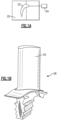
Figure 1A schematically shows a die. -
Figure 1B schematically shows a gas turbine engine airfoil component formed by a die. -
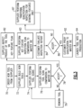
Figure 2 is a flow chart of a method for certifying a master die initially. -
Figure 3 is a flow chart associated with theFigure 2 method, and wherein an additional die may be certified based upon comparison to a certified master die. -
Figure 4 shows a scanning system to be used in this method. -
Figure 5 shows a comparison between two scans. -
Figure 1A shows a die 20 schematically. As known, acavity 22 receives injected metal from asource 24. - One component which may be formed by such a die is shown in
Figure 1B . Here aturbine blade 26 has anairfoil 25. While a turbine blade is specifically disclosed, it should be understood that other gas turbine engine components may be formed using metal cast dies such as theFigure 1A die. - As well known, airfoils are complex structures, and have demanding dimensional challenges in forming the desired structure. For this reason, dies to form an airfoil are subject to intense qualification tests before being utilized to make production airfoils.
- In the prior art, and before a die is utilized in production, it must first be certified.
- In one common method of certification, the die is built, and then utilized to produce what is called a qualification lot. As an example, this may be on the order of two dozen components, or more. Those produced components are then inspected and compared to desired dimensions, etc. It is only after this inspection has been passed that the die would be moved toward production. In the prior art, this qualification was performed not only for an initial die, but for all subsequent dies made to be identical to an initial or master die.
-
Figure 2 shows amethod 38 for qualifying an initial or master die under this disclosure. Atstep 40, a die may be ordered. The die is then designed and built as a master die atstep 42. - A traditional inspection is then performed on the qualification lot at
step 46. The results, or the layout, are evaluated atstep 48. - At
step 50, a decision is made whether to accept the layout. If not, the die is reworked atstep 52, and the flow chart returns tostep 44. - If the layout is accepted at
step 50 then,
a 3D scan of a master die is performed atstep 53. In one embodiment, a structured light scan may be utilized to scan the master die. - At
step 58 an inspection is made of products of the tool via a key feature plan. Atstep 59 inspection data is retained and the master die is launched into production atstep 62. - Notably, the
steps -
Figure 4 schematically shows asimple system 100 for performing the 3D scans. As shown, acamera 102 takes photos of the interior of thecavity 22 as illuminated by a structuredlight scanning system 104. Other type scanning systems may be used. - The initial master die scan is preferably compared to a die model to ensure the die scan's integrity.
- At step 54 a die inspection plan is proposed, and a decision is made whether the die inspection plan is acceptable at
step 56. If not, the flow chart returns tostep 54 such that the inspection plan may be modified. Key features are inspected on the product of the die atstep 58, and compared to the Master Die key feature inspection. - The evidence may be a simple product of a die thickness across both die halves, and at both die cavity ends.
- In
Figure 3 , atstep 70 an additional die is ordered. Atstep 72 the additional die is built. - At step 74 a 3D scan of the additional die, such as by structured light scanning is performed. Again, the
Figure 4 system may be used. - At
step 76 the 3D scan of the additional die is then compared to the scanned information from the master die.Figure 5 shows amap 100 of the two scans overlied on each other for comparison (step 76). A scale is shown to the right to facilitate the comparison. - Notably, the structured light software utilized for the master die is preferably the same as that utilized for the additional die. Moreover, the same company will preferably do both scans and will ensure proper die preparation, camera position and view angles such that these are all the same for both scans.
- At
step 78 the question is asked whether the results meet the requirements. - If the results do not meet requirements at
step 78 then the tool is reworked atstep 79, and returned to step 74. - If the result of
step 78 is that the additional die is found acceptable, then there will be an inspection of product of the tool via a key feature plan atstep 82. Atstep 83, a key feature inspection plan is compared to the master die atstep 83. Atstep 84, the inspection report is evaluated. Atstep 86, a decision is made whether the inspection report is acceptable. If not, then it returns to step 87 where a traditional qualification inspection is provided only for deviating features. - If the additional die is found acceptable at
step 86 then the die is provided with proxy qualification due to its closeness to the master die atstep 92, and launched into production atstep 94. - Notably, as with the
Figure 2 method, the bulk of theFigure 3 steps may be performed by a supplier. Namely steps 72, 74, 76, 78, 79, 82, 83 and 87 may all be performed by the supplier, with a customer for the additional die of performing the other steps. Here again, the supplier would be working at the direction of the customer. Also, a single company may provide the role of both supplier and customer in embodiments. - If there are subsequent changes to the casting process that change the master die, it may be that the changed die must then be requalified using the
Figure 2 flow chart. - A method of qualifying an addition die under this disclosure could be said to include the steps of obtaining a master die that has been certified, and performing a master 3D scan on the master die. A second 3D scan is performed on an additional die made according to original specifications of the master die. The second 3D scan is compared to the master 3D scan of the master die. Then, the additional die is certified for production should the second 3D scan of the additional die be acceptably close to the master 3D scan of the master die.
- In another embodiment according to the previous embodiment, the addition die is utilized in production to form components.
- In another embodiment according to any of the previous embodiments, the component includes an airfoil.
- In another embodiment according to any of the previous embodiments, the master die is qualified by building a master die, and producing a qualification lot of components from the master die, then performing inspection on the qualification lot components and accepting or rejecting the master die based upon that inspection.
- In another embodiment according to any of the previous embodiments, if the master die is rejected, then the master die is reworked and returned to produce an additional qualification lot for inspection.
- In another embodiment according to any of the previous embodiments, if the second 3D scan of the additional die is not acceptably close to the master 3D scan of the master die then the additional die is reworked and a third scan is taken and compared to the master scan.
- In another embodiment according to any of the previous embodiments, the master 3D scan and the second 3D scan are performed using structured light scanning.
- In another embodiment according to any of the previous embodiments, if the second 3D scan of the additional die is not acceptably close to the master 3D of the master die scan then the additional die is reworked and a third scan is taken and compared to the master scan.
- In another embodiment according to any of the previous embodiments, the master 3D scan and the second 3D scan are performed using structured light scanning.
- In another embodiment according to any of the previous embodiments, the master die is qualified by building a master die, and producing a qualification lot of components from the master die, then performing inspection on the qualification lot components and accepting or rejecting the master die based upon that inspection.
- In another embodiment according to any of the previous embodiments, if the master die is rejected, then the master die is reworked and returned to produce an additional qualification lot for inspection.
- In another embodiment according to any of the previous embodiments, if the second 3D scan of the additional die is not acceptably close to the master 3D scan of the master die then the additional die is reworked and a third scan is taken and compared to the master scan.
- In another embodiment according to any of the previous embodiments, the master 3D scan and the second 3D scan are performed using structured light scanning.
- In another embodiment according to any of the previous embodiments, if the second 3D scan of the additional die is not acceptably close to the master 3D scan of the master die then the additional die is reworked and a third scan is taken and compared to the master scan.
- In another embodiment according to any of the previous embodiments, the master 3D scan and the second 3D scan are performed using structured light scanning.
- In another embodiment according to any of the previous embodiments, the master die is qualified by building a master die, and producing a qualification lot of components from the master die, then performing inspection on the qualification lot components and accepting or rejecting the master die based upon that inspection.
- In another embodiment according to any of the previous embodiments, if the master die is rejected, then the master die is reworked and returned to produce an additional qualification lot for inspection.
- In another embodiment according to any of the previous embodiments, if the second 3D scan of the additional die is not acceptably close to the master 3D scan of the master die then the additional die is reworked and a third scan is taken and compared to the master scan.
- In another embodiment according to any of the previous embodiments, if the second 3D scan of the additional die is not acceptably close to the master 3D scan of the master die then the additional die is reworked and a third scan is taken and compared to the master scan.
- In another embodiment according to any of the previous embodiments, the master 3D scan and the second 3D scan are performed using structured light scanning.
- An addition die may be called an additional die and vice versa.
- Although embodiments have been disclosed, a worker of skill in this art would recognize that modifications would come within the scope of this disclosure. For that reason, the following claims should be studied to determine the true scope and content.
Claims (7)
- A method of qualifying an addition die (20) comprising the steps of:obtaining a master die that has been certified, and performing a master 3D scan on the master die;performing a second 3D scan on an additional die (20) made according to specifications of the master die;comparing the master 3D scan of the master die to the second 3D scan of the additional die (20); andcertifying the additional die (20) for production should the second 3D scan of the additional die (20) be acceptably close to the master 3D scan of the master die.
- The method as set forth in claim 1, wherein the addition die (20) is utilized in production to form components (26).
- The method as set forth in claim 2, wherein the component (26) includes an airfoil (25).
- The method as set forth in any preceding claim, wherein the master die is qualified by building a master die, and producing a qualification lot of components (26) from the master die, then performing inspection on the qualification lot of components (26) and accepting or rejecting the master die based upon that inspection.
- The method as set forth in any preceding claim, wherein if the master die is rejected, then the master die is reworked and returned to produce an additional qualification lot for inspection.
- The method as set forth in any preceding claim, wherein if the second 3D scan of the additional die (20) is not acceptably close to the master 3D scan of the master die then the additional die (20) is reworked and a third scan is taken and compared to the master scan.
- The method as set forth in any preceding claim, wherein the master 3D scan and the second 3D scan are performed using structured light scanning.
Applications Claiming Priority (1)
| Application Number | Priority Date | Filing Date | Title |
|---|---|---|---|
| US18/392,890 US20250209607A1 (en) | 2023-12-21 | 2023-12-21 | Method to qualify additional dies after master die |
Publications (1)
| Publication Number | Publication Date |
|---|---|
| EP4574302A1 true EP4574302A1 (en) | 2025-06-25 |
Family
ID=93853266
Family Applications (1)
| Application Number | Title | Priority Date | Filing Date |
|---|---|---|---|
| EP24218869.6A Pending EP4574302A1 (en) | 2023-12-21 | 2024-12-10 | Method to qualify additional dies with master die |
Country Status (2)
| Country | Link |
|---|---|
| US (1) | US20250209607A1 (en) |
| EP (1) | EP4574302A1 (en) |
Citations (3)
| Publication number | Priority date | Publication date | Assignee | Title |
|---|---|---|---|---|
| US20040262277A1 (en) * | 2003-06-30 | 2004-12-30 | Mika David P. | Airfoil qualification system and method |
| WO2016193790A1 (en) * | 2015-06-04 | 2016-12-08 | Disa Industries A/S | Sand moulding machine and method of producing sand mould parts |
| EP4249727A2 (en) * | 2022-03-23 | 2023-09-27 | Raytheon Technologies Corporation | Airfoil tool mount |
Family Cites Families (3)
| Publication number | Priority date | Publication date | Assignee | Title |
|---|---|---|---|---|
| US20040151611A1 (en) * | 2003-01-30 | 2004-08-05 | Kline Kerry J. | Method for producing powder metal tooling, mold cavity member |
| CN113646112A (en) * | 2019-04-24 | 2021-11-12 | 住友电工烧结合金株式会社 | Sintered body manufacturing system and manufacturing method |
| US12590797B2 (en) * | 2023-12-21 | 2026-03-31 | Pratt & Whitney Canada Corp. | Method to requalify die after storage |
-
2023
- 2023-12-21 US US18/392,890 patent/US20250209607A1/en active Pending
-
2024
- 2024-12-10 EP EP24218869.6A patent/EP4574302A1/en active Pending
Patent Citations (3)
| Publication number | Priority date | Publication date | Assignee | Title |
|---|---|---|---|---|
| US20040262277A1 (en) * | 2003-06-30 | 2004-12-30 | Mika David P. | Airfoil qualification system and method |
| WO2016193790A1 (en) * | 2015-06-04 | 2016-12-08 | Disa Industries A/S | Sand moulding machine and method of producing sand mould parts |
| EP4249727A2 (en) * | 2022-03-23 | 2023-09-27 | Raytheon Technologies Corporation | Airfoil tool mount |
Non-Patent Citations (1)
| Title |
|---|
| ANONYMOUS: "how to use 3D scanning for metal parts", 24 February 2021 (2021-02-24), XP093272465, Retrieved from the Internet <URL:https://www.die-casting-china.com/en/Design/3D_Scanning/> [retrieved on 20250424] * |
Also Published As
| Publication number | Publication date |
|---|---|
| US20250209607A1 (en) | 2025-06-26 |
Similar Documents
| Publication | Publication Date | Title |
|---|---|---|
| US20230294221A1 (en) | Method and arrangement for repairing a workpiece | |
| Ríos et al. | Uncertainty of data and the digital twin: a review | |
| US6882893B2 (en) | Method of designing product using 3-dimensional model | |
| EP4574307A1 (en) | Method to requalify die after storage | |
| US20130041635A1 (en) | Methods and Systems for Designing Addendum Section of A Die in Sheet Metal Forming | |
| US20250209607A1 (en) | Method to qualify additional dies after master die | |
| CA3258780A1 (en) | Method to qualify additional dies after master die | |
| Petrov et al. | Applying 3D-scan systems rangevision for precision preparing of polygonal 3D-models | |
| CN100369067C (en) | Curve construction method of intercept cloud in 3D scanning system | |
| CN116702443A (en) | Method, device, equipment and storage medium for adjusting hole system of engine cylinder block casting | |
| CN116204974A (en) | Method for evaluating geometric consistency of CAD model of aeroengine blade part | |
| Fedosova et al. | The automated method of metrological inspection of parts manufactured according to additive technology using the 3D Scanning method | |
| CN115069981A (en) | Method for determining trimming modulus of casting mold | |
| Chant et al. | The determination of IC engine inlet port geometries by reverse engineering | |
| Galiulin et al. | Optoelectronic computer-aided systems for inspection of gas-turbine engine complex objects | |
| JP2003344026A (en) | Computer program and method for inspecting hollow vane | |
| CN111590265A (en) | Mould repairing method based on laser scanning technology | |
| CN120197288A (en) | Ship digital prototype and its construction method | |
| US20240037909A1 (en) | Performing vane classification for turbine engines using structured light three-dimensional (3d) scans | |
| CN120951641A (en) | Methods, devices, equipment and media for predicting the life of high-pressure turbine blades in engines | |
| Fedosova et al. | The Automated Method of Metrological | |
| Starinieri | Hitchiner Manufacturing | |
| CN115266933A (en) | Rapid nondestructive testing method for composite part based on rough sampling point | |
| Matache et al. | SETUP AND TESTING OF A 3D SCANNING METHOD FOR DIMENSIONAL INSPECTION OF A SMALL SIZE CAST TURBINE BLADE | |
| CN121067704A (en) | Method and system for calibrating gap sensor of actual configuration of blade tip of aero-engine blade |
Legal Events
| Date | Code | Title | Description |
|---|---|---|---|
| PUAI | Public reference made under article 153(3) epc to a published international application that has entered the european phase |
Free format text: ORIGINAL CODE: 0009012 |
|
| STAA | Information on the status of an ep patent application or granted ep patent |
Free format text: STATUS: THE APPLICATION HAS BEEN PUBLISHED |
|
| AK | Designated contracting states |
Kind code of ref document: A1 Designated state(s): AL AT BE BG CH CY CZ DE DK EE ES FI FR GB GR HR HU IE IS IT LI LT LU LV MC ME MK MT NL NO PL PT RO RS SE SI SK SM TR |
|
| STAA | Information on the status of an ep patent application or granted ep patent |
Free format text: STATUS: REQUEST FOR EXAMINATION WAS MADE |
|
| 17P | Request for examination filed |
Effective date: 20251231 |