EP4574251A1 - Spliced ceramic sheet and ceramic sheet liner - Google Patents

Spliced ceramic sheet and ceramic sheet liner Download PDF

Info

Publication number
EP4574251A1
EP4574251A1 EP24186372.9A EP24186372A EP4574251A1 EP 4574251 A1 EP4574251 A1 EP 4574251A1 EP 24186372 A EP24186372 A EP 24186372A EP 4574251 A1 EP4574251 A1 EP 4574251A1
Authority
EP
European Patent Office
Prior art keywords
mating
ceramic sheet
spliced
spliced ceramic
groove
Prior art date
Legal status (The legal status is an assumption and is not a legal conclusion. Google has not performed a legal analysis and makes no representation as to the accuracy of the status listed.)
Pending
Application number
EP24186372.9A
Other languages
German (de)
French (fr)
Inventor
Ziyi Yu
Wanli SUN
Current Assignee (The listed assignees may be inaccurate. Google has not performed a legal analysis and makes no representation or warranty as to the accuracy of the list.)
Hunan Ongoal Intelligent Technology Co Ltd
Original Assignee
Hunan Ongoal Intelligent Technology Co Ltd
Priority date (The priority date is an assumption and is not a legal conclusion. Google has not performed a legal analysis and makes no representation as to the accuracy of the date listed.)
Filing date
Publication date
Application filed by Hunan Ongoal Intelligent Technology Co Ltd filed Critical Hunan Ongoal Intelligent Technology Co Ltd
Publication of EP4574251A1 publication Critical patent/EP4574251A1/en
Pending legal-status Critical Current

Links

Images

Classifications

    • HELECTRICITY
    • H01ELECTRIC ELEMENTS
    • H01MPROCESSES OR MEANS, e.g. BATTERIES, FOR THE DIRECT CONVERSION OF CHEMICAL ENERGY INTO ELECTRICAL ENERGY
    • H01M50/00Constructional details or processes of manufacture of the non-active parts of electrochemical cells other than fuel cells, e.g. hybrid cells
    • H01M50/10Primary casings; Jackets or wrappings
    • H01M50/116Primary casings; Jackets or wrappings characterised by the material
    • H01M50/124Primary casings; Jackets or wrappings characterised by the material having a layered structure
    • H01M50/1243Primary casings; Jackets or wrappings characterised by the material having a layered structure characterised by the internal coating on the casing
    • CCHEMISTRY; METALLURGY
    • C04CEMENTS; CONCRETE; ARTIFICIAL STONE; CERAMICS; REFRACTORIES
    • C04BLIME, MAGNESIA; SLAG; CEMENTS; COMPOSITIONS THEREOF, e.g. MORTARS, CONCRETE OR LIKE BUILDING MATERIALS; ARTIFICIAL STONE; CERAMICS; REFRACTORIES; TREATMENT OF NATURAL STONE
    • C04B35/00Shaped ceramic products characterised by their composition; Ceramics compositions; Processing powders of inorganic compounds preparatory to the manufacturing of ceramic products
    • BPERFORMING OPERATIONS; TRANSPORTING
    • B01PHYSICAL OR CHEMICAL PROCESSES OR APPARATUS IN GENERAL
    • B01FMIXING, e.g. DISSOLVING, EMULSIFYING OR DISPERSING
    • B01F35/00Accessories for mixers; Auxiliary operations or auxiliary devices; Parts or details of general application
    • B01F35/50Mixing receptacles
    • B01F35/511Mixing receptacles provided with liners, e.g. wear resistant or flexible liners
    • HELECTRICITY
    • H01ELECTRIC ELEMENTS
    • H01MPROCESSES OR MEANS, e.g. BATTERIES, FOR THE DIRECT CONVERSION OF CHEMICAL ENERGY INTO ELECTRICAL ENERGY
    • H01M50/00Constructional details or processes of manufacture of the non-active parts of electrochemical cells other than fuel cells, e.g. hybrid cells
    • H01M50/10Primary casings; Jackets or wrappings
    • H01M50/116Primary casings; Jackets or wrappings characterised by the material
    • H01M50/117Inorganic material
    • CCHEMISTRY; METALLURGY
    • C04CEMENTS; CONCRETE; ARTIFICIAL STONE; CERAMICS; REFRACTORIES
    • C04BLIME, MAGNESIA; SLAG; CEMENTS; COMPOSITIONS THEREOF, e.g. MORTARS, CONCRETE OR LIKE BUILDING MATERIALS; ARTIFICIAL STONE; CERAMICS; REFRACTORIES; TREATMENT OF NATURAL STONE
    • C04B2235/00Aspects relating to ceramic starting mixtures or sintered ceramic products
    • C04B2235/70Aspects relating to sintered or melt-casted ceramic products
    • C04B2235/96Properties of ceramic products, e.g. mechanical properties such as strength, toughness, wear resistance
    • HELECTRICITY
    • H01ELECTRIC ELEMENTS
    • H01MPROCESSES OR MEANS, e.g. BATTERIES, FOR THE DIRECT CONVERSION OF CHEMICAL ENERGY INTO ELECTRICAL ENERGY
    • H01M10/00Secondary cells; Manufacture thereof
    • H01M10/05Accumulators with non-aqueous electrolyte
    • H01M10/052Li-accumulators

Definitions

  • the present application relates to the technical field of material processing, and in particular to a spliced ceramic sheet and a ceramic sheet liner.
  • a non-metallic liner is commonly added to the inner wall of the cavity.
  • ceramic liners offer several advantages: good wear resistance, low cost, wide applicability, low operating resistance, corrosion resistance, scale prevention, excellent temperature resistance, and thermal shock resistance, as well as easy installation and construction.
  • the main objective of the present application is to provide a spliced ceramic sheet and a ceramic sheet liner thereof, aiming to solve the problem of unstable connection between spliced ceramic sheets in the related art.
  • the present application provides a spliced ceramic sheet including two mating side surfaces opposite to each other.
  • one mating side surface is provided with a mating rib and another mating side surface is provided with a mating groove, and the mating groove runs through both ends of the mating side surface in a length direction.
  • the mating rib of the spliced ceramic sheet is configured to be installed in the mating groove of an adjacent spliced ceramic sheet, a positioning structure is formed between the mating rib and the mating groove, and the positioning structure is configured to position the mating rib in the mating groove.
  • a positioning protrusion is provided on one surface of opposite side walls of the mating rib and the mating groove, a cooperation groove is recessed on another surface of the opposite side walls of the mating rib and the mating groove, and the positioning protrusion is snap-fitted and positioned in the cooperation groove.
  • the positioning protrusion and the cooperation groove form a positioning group, and a plurality of positioning groups are provided at intervals.
  • the mating rib and the mating groove form a mating group, and a plurality of mating groups are provided at intervals along a width direction of the mating side surface.
  • the spliced ceramic sheet is configured to extend in an arc shape along a length direction of the mating side surface.
  • a spacing between the two mating side surfaces is gradually reduced along the length direction of the mating side surface.
  • the spliced ceramic sheet further comprises two connection side surfaces opposite to each other, the two connection side surfaces are located between the two mating side surfaces, the connection side surface of the spliced ceramic sheet is configured to connect to the connection side surface of another spliced ceramic sheet, and a sealing structure is formed between the two connection side surfaces on the two adjacent spliced ceramic sheets.
  • one of the two connection side surfaces on two adjacent spliced ceramic sheets forms a guide slope
  • the guide slope is inclined along a thickness direction of the spliced ceramic sheet
  • another connection side surface is correspondingly formed with a matching slope
  • the matching slope is configured to fit onto the guide slope
  • connection side surfaces are extended in an arc shape along a length direction of the connection side surface.
  • the present application further provides a ceramic sheet liner, including the above-mentioned spliced ceramic sheet.
  • a ceramic sheet liner including the above-mentioned spliced ceramic sheet.
  • a plurality of spliced ceramic sheets are provided, and are spliced with each other.
  • mating ribs and mating grooves are respectively formed on the two mating side surfaces of the spliced ceramic sheets.
  • the corresponding mating ribs in the two adjacent spliced ceramic sheets are installed into the mating grooves, so that the two spliced ceramic sheets are fixedly connected.
  • the mating ribs are positioned in the mating grooves, ensuring a stable connection between the two adjacent spliced ceramic sheets and avoiding position shaking.

Landscapes

  • Chemical & Material Sciences (AREA)
  • Engineering & Computer Science (AREA)
  • Chemical Kinetics & Catalysis (AREA)
  • Ceramic Engineering (AREA)
  • Electrochemistry (AREA)
  • General Chemical & Material Sciences (AREA)
  • Structural Engineering (AREA)
  • Organic Chemistry (AREA)
  • Materials Engineering (AREA)
  • Manufacturing & Machinery (AREA)
  • Inorganic Chemistry (AREA)
  • Laminated Bodies (AREA)
  • Ceramic Products (AREA)
  • Insulating Bodies (AREA)

Abstract

Disclosed are a spliced ceramic sheet (100) and a ceramic sheet liner thereof. The spliced ceramic sheet (100) includes two mating side surfaces (1) opposite to each other. One mating side surface (1) is provided with a mating rib (11) and another mating side surface (1) is provided with a mating groove (12), and the mating groove (12) runs through both ends of the mating side surface (1) in a length direction. The mating rib (11) of the spliced ceramic sheet (100) is configured to be installed in the mating groove (12) of an adjacent spliced ceramic sheet (100), a positioning structure is formed between the mating rib (11) and the mating groove (12), and the positioning structure is configured to position the mating rib (11) in the mating groove (12).

Description

    TECHNICAL FIELD
  • The present application relates to the technical field of material processing, and in particular to a spliced ceramic sheet and a ceramic sheet liner.
  • BACKGROUND
  • Currently, in the material processing industry, to prevent direct contact between materials and metal, a non-metallic liner is commonly added to the inner wall of the cavity. Among these, ceramic liners offer several advantages: good wear resistance, low cost, wide applicability, low operating resistance, corrosion resistance, scale prevention, excellent temperature resistance, and thermal shock resistance, as well as easy installation and construction.
  • At present, most equipment manufacturers commonly use small flat ceramic sheets spliced and adhered together to create wear-resistant liners. However, the adhesion between the ceramic sheets is not stable, resulting in gaps between the tiles. Additionally, there are gaps between the ceramic sheets and the inner wall of the equipment, which ultimately leads to the ceramic sheets easily falling off. Therefore, the connection between spliced ceramic sheets in the related art is not stable.
  • SUMMARY
  • The main objective of the present application is to provide a spliced ceramic sheet and a ceramic sheet liner thereof, aiming to solve the problem of unstable connection between spliced ceramic sheets in the related art.
  • In order to achieve the above objective, the present application provides a spliced ceramic sheet including two mating side surfaces opposite to each other.
  • In an embodiment, one mating side surface is provided with a mating rib and another mating side surface is provided with a mating groove, and the mating groove runs through both ends of the mating side surface in a length direction.
  • In an embodiment, the mating rib of the spliced ceramic sheet is configured to be installed in the mating groove of an adjacent spliced ceramic sheet, a positioning structure is formed between the mating rib and the mating groove, and the positioning structure is configured to position the mating rib in the mating groove.
  • In an embodiment, a positioning protrusion is provided on one surface of opposite side walls of the mating rib and the mating groove, a cooperation groove is recessed on another surface of the opposite side walls of the mating rib and the mating groove, and the positioning protrusion is snap-fitted and positioned in the cooperation groove.
  • In an embodiment, the positioning protrusion and the cooperation groove form a positioning group, and a plurality of positioning groups are provided at intervals.
  • In an embodiment, the mating rib and the mating groove form a mating group, and a plurality of mating groups are provided at intervals along a width direction of the mating side surface.
  • In an embodiment, the spliced ceramic sheet is configured to extend in an arc shape along a length direction of the mating side surface.
  • In an embodiment, a spacing between the two mating side surfaces is gradually reduced along the length direction of the mating side surface.
  • In an embodiment, the spliced ceramic sheet further comprises two connection side surfaces opposite to each other, the two connection side surfaces are located between the two mating side surfaces, the connection side surface of the spliced ceramic sheet is configured to connect to the connection side surface of another spliced ceramic sheet, and a sealing structure is formed between the two connection side surfaces on the two adjacent spliced ceramic sheets.
  • In an embodiment, one of the two connection side surfaces on two adjacent spliced ceramic sheets forms a guide slope, the guide slope is inclined along a thickness direction of the spliced ceramic sheet, another connection side surface is correspondingly formed with a matching slope, and the matching slope is configured to fit onto the guide slope.
  • In an embodiment, the two connection side surfaces are extended in an arc shape along a length direction of the connection side surface.
  • The present application further provides a ceramic sheet liner, including the above-mentioned spliced ceramic sheet. A plurality of spliced ceramic sheets are provided, and are spliced with each other.
  • In the spliced ceramic sheets provided in the present application, mating ribs and mating grooves are respectively formed on the two mating side surfaces of the spliced ceramic sheets. During installation, the corresponding mating ribs in the two adjacent spliced ceramic sheets are installed into the mating grooves, so that the two spliced ceramic sheets are fixedly connected. Additionally, through the positioning structure between the mating ribs and the mating grooves, after installation in place, the mating ribs are positioned in the mating grooves, ensuring a stable connection between the two adjacent spliced ceramic sheets and avoiding position shaking.
  • BRIEF DESCRIPTION OF THE DRAWINGS
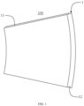
    • FIG. 1 is a schematic diagram of three-dimensional structure of a spliced ceramic sheet according to an embodiment of the present application.
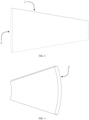
    • FIG. 2 is a schematic diagram of the three-dimensional structure of the spliced ceramic sheet according to another embodiment of the present application.
    • FIG. 3 is a schematic diagram of the three-dimensional structure of the spliced ceramic sheet according to another embodiment of the present application.
    • FIG. 4 is a schematic diagram of the three-dimensional structure of a ceramic sheet liner according to an embodiment of the present application.
  • Explanation of reference signs:
    Reference sign Name Reference sign Name
    100 splicing ceramic sheet 12 mating groove
    1 mating side surface 2 connection side surface
    11 mating rib
  • The objective, features and advantages of the present application will be further described in conjunction with the embodiments and with reference to the accompanying drawings.
  • DETAILED DESCRIPTION OF THE EMBODIMENTS
  • The technical solutions in the embodiments of the present application will be clearly and completely described below with reference to the drawings in the embodiment of the present application. Obviously, the described embodiments are only a part of the embodiments of the present application, not all of the embodiments. Based on the embodiments in the present application, all other embodiments perceived by those skilled in the art without creative effort should be fallen within the protection scope of the present application.
  • It should be noted that all of the directional instructions in the embodiments of the present application (such as, up, down, left, right, front, rear....) are only used to explain the relative position relationship and movement of each component under a specific attitude (as shown in the drawings), if the specific attitude changes, the directional instructions will change correspondingly.
  • Besides, the descriptions in the present application that refer to "first," "second," etc. are only for descriptive purposes and are not to be interpreted as indicating or implying relative importance or to implicitly indicate the number of technical features indicated. Thus, a feature defined as "first" or "second" may explicitly or implicitly include at least one of the features. In addition, the meaning of "and/or" appearing in the entire text is to include three parallel solutions. For example, "A and/or B" includes only A, or only B, or both A and B. In addition, technical solutions between the embodiments can be combined with each other, but must be based on the realization of the technical solutions by those skilled in the art, and when the technical solutions are contradictory to each other or cannot be realized, the technical solutions should be considered that the combination does not exist, and the technical solutions are not fallen within the protection scope claimed in the present application.
  • As shown in FIG. 1, the present application provides a spliced ceramic sheet 100. The spliced ceramic sheet 100 includes two mating side surfaces 1 opposite to each other. A mating rib 11 is provided on one of the mating side surfaces 1. A mating groove 12 is provided on another mating side surface 1. The mating groove 12 runs through both ends of the mating side surface 1 where it is located in the length direction. The mating rib 11 of the spliced ceramic sheet 100 is configured to be installed in the mating groove 12 of the adjacent spliced ceramic sheet 100. A positioning structure is formed between the mating rib 11 and the mating groove 12. The positioning structure is configured to position the mating rib 11 in the mating groove 12.
  • In the spliced ceramic sheet 100 provided in the present application, a mating rib 11 is formed on one mating side surface 1 of the spliced ceramic sheet 100 and a mating groove 12 is formed on another mating side surface 1 of the spliced ceramic sheet 100. During installation, the corresponding mating rib 11 in the two adjacent spliced ceramic sheets 100 is installed into the mating groove 12, so that the two spliced ceramic sheets 100 are fixedly connected. Additionally, through the positioning structure between the mating rib 11 and the mating groove 12, after installation in place, the mating rib 11 is positioned in the mating groove 12, ensuring a stable connection between the two adjacent spliced ceramic sheets 100, and avoiding position shaking.
  • It should be noted that the positioning structure has multiple implementations. For example, positioning holes are respectively provided on the opposite side walls of the mating rib 11 and the mating groove 12. The positioning is performed by external positioning pins.
  • In an embodiment, one of the opposite side walls of the mating rib 11 and the mating groove 12 is provided with a positioning protrusion, and another surface of the opposite side walls is recessed with a cooperation groove. The positioning protrusion is snap-fitted and positioned in the cooperation groove. In an embodiment, the self-positioning of the mating rib 11 and the mating groove 12 is achieved by means of the positioning protrusion and the cooperation groove, without relying on external parts, which facilitates rapid positioning.
  • In an embodiment, the positioning protrusion and the cooperation groove form a positioning group. A plurality of positioning groups are provided at intervals to facilitate the stability of positioning.
  • It should be noted that, in an embodiment, the positioning protrusion forms an interference fit between the mating rib and the mating groove, and the cooperation groove is configured to accommodate the positioning protrusion. Therefore, during the installation process, when the positioning protrusion moves into the cooperation groove, the positioning protrusion cannot automatically leave the cooperation groove.
  • In order to ensure the stability of the connection between the two adjacent spliced ceramic sheets, the mating ribs 11 and the mating grooves 12 form a mating group. A plurality of mating groups are provided at intervals along the width direction of the mating side surface 1. So that when the spliced ceramic sheets 100 with larger thickness are connected, the plurality of mating groups can be configured to stabilize in the thickness direction, which avoids the problem that a single mating group connection is easily damaged and causes the positioning failure.
  • In an embodiment provided in the present application, the spliced ceramic sheet 100 is extended in an arc shape along the length direction of the mating side surface 1, so that the spliced ceramic sheet 100 is provided in an arc-shaped plate, and a plurality of the spliced ceramic sheets 100 can be mated to form a ring, so as to form an inner liner.
  • As shown in FIG. 2, the spacing between the two butting sides 1 is gradually reduced along the length direction. In an embodiment, it is convenient to adapt to the splicing environment with complex inner diameter, so that the spliced ceramic sheet 100 is provided in a trapezoidal shape.
  • In another embodiment provided in the present application, the spliced ceramic sheet 100 also includes two connection side surfaces 2 opposite to each other, and two connection side surfaces are located between the two mating side surfaces 1. The connection side surface 2 of the spliced ceramic sheet 100 is configured to connect to the connection side surface 2 of another spliced ceramic sheet 100. A sealing structure is formed between the two connection side surfaces 2 on two adjacent spliced ceramic sheets 100. In an embodiment, the spliced ceramic sheets 100 can be spliced not only along the width direction of the mating side surface 1, but also in the length direction of the mating side surface 1, so as to form ceramic protective surfaces of different sizes. A sealing structure is provided between the two adjacent connection side surfaces 2 to ensure the sealing between the two adjacent spliced ceramic sheets and avoid the gap between the two adjacent spliced ceramic sheets 100 being too large.
  • In an embodiment, one of the two connection side surfaces 2 on the two adjacent spliced ceramic sheets 100 forms a guide slope. The guide slope is inclined along the thickness direction of the spliced ceramic sheet 100. A matching slope is correspondingly formed on another connection side surface. The matching slope is configured to fit onto the guide slope. In an embodiment, through the matching guide slope and the matching slope, during the installation process, the two connection side surfaces 2 are fitted along the slope, and the gap is transferred to the slope and the end face of the spliced ceramic sheet 100. The gap can thus be effectively reduced. And during the installation process, the gap has a certain three-dimensional extension, so as to avoid falling off between the two adjacent spliced ceramic sheets 100 during shaking, and can automatically return to their original position along the slope.
  • In addition, as shown in FIG. 3, the spliced ceramic sheets 100 are extended in an arc shape along the length direction of the connection side surface, so as to form an arc-shaped plate and to be spliced at different angles.
  • As shown in FIG. 4, based on the above-mentioned spliced ceramic sheet 100, the present application further provides a ceramic sheet liner. The ceramic sheet liner includes all the technical features of the above-mentioned spliced ceramic sheet 100. Therefore, it also has the technical effects brought by all the above-mentioned technical features, and description will be repeated here.
  • In the ceramic sheet liner provided in the present application, a plurality of the spliced ceramic sheets 100 are provided. The plurality of spliced ceramic sheets are spliced with each other to facilitate liner protection.
  • The spliced ceramic sheets 100 provided by the present application can be widely used as a ceramic liner in various equipment within the material processing field. For instance, this technology can be applied to enhance the durability and performance of plow mixers, paddle dryers, and jet mills.
  • In plow mixers, materials generate significant friction and impact on the equipment's inner walls during mixing. By installing the spliced ceramic sheets 100 on the inner walls, the service life of the equipment can be effectively extended. The installation process involves splicing multiple spliced ceramic sheets 100 along the inner wall, where the mating rib 11 and mating groove 12 interlock to secure the connection. The positioning structure between the mating rib 11 and mating groove 12 ensures accurate positioning of each ceramic sheet, preventing loosening or detachment due to vibrations during mixing.
  • In paddle dryers, the drying process often involves high temperatures and chemical corrosion, which can damage traditional metal liners. The spliced ceramic sheets 100 provided in this application exhibit excellent heat resistance and corrosion resistance, maintaining stability in such environments. The ceramic sheets are spliced along the inner wall of the paddle dryer, with the mating rib 11 and mating groove 12 interlocking, and the positioning structure ensuring stability and sealing, thereby enhancing the equipment's durability and efficiency.
  • In j et mills, the high-speed airflow causes severe wear on the equipment's inner walls. The use of spliced ceramic sheets 100 can effectively reduce wear and extend the maintenance cycle of the equipment. The installation involves splicing the ceramic sheets along the inner wall of the jet mill, with the mating rib 11 and mating groove 12 interlocking to form a tight connection. The positioning structure ensures that each ceramic sheet remains in place under high-speed airflow, maintaining the integrity of the inner wall.
  • The above are only some embodiments of the present application, and do not limit the scope of the present application thereto. Under the inventive concept of the present application, equivalent structural transformations made according to the description and drawings of the present application, or direct/indirect application in other related technical fields are included in the scope of the present application.
Claims (10)

  1. A spliced ceramic sheet (100), characterized by comprising: two mating side surfaces (1) opposite to each other, wherein:
    one mating side surface (1) is provided with a mating rib (11) and another mating side surface (1) is provided with a mating groove (12), and the mating groove (12) runs through both ends of the mating side surface (1) in a length direction;
    the mating rib (11) of the spliced ceramic sheet (100) is configured to be installed in the mating groove (12) of an adjacent spliced ceramic sheet (100), a positioning structure is formed between the mating rib (11) and the mating groove (12), and the positioning structure is configured to position the mating rib (11) in the mating groove (12).
  2. The spliced ceramic sheet (100) according to claim 1, wherein a positioning protrusion is provided on one surface of opposite side walls of the mating rib (11) and the mating groove (12), a cooperation groove is recessed on another surface of the opposite side walls of the mating rib (11) and the mating groove (12), and the positioning protrusion is snap-fitted and positioned in the cooperation groove.
  3. The spliced ceramic sheet (100) according to claim 2, wherein the positioning protrusion and the cooperation groove form a positioning group, and a plurality of positioning groups are provided at intervals.
  4. The spliced ceramic sheet (100) according to claim 1, wherein the mating rib (11) and the mating groove (12) form a mating group, and a plurality of mating groups are provided at intervals along a width direction of the mating side surface (1).
  5. The spliced ceramic sheet (100) according to claim 1, wherein the spliced ceramic sheet (100) is configured to extend in an arc shape along a length direction of the mating side surface (1).
  6. The spliced ceramic sheet (100) according to claim 1, wherein a spacing between the two mating side surfaces (1) is gradually reduced along the length direction of the mating side surface (1).
  7. The spliced ceramic sheet (100) according to claim 1, wherein the spliced ceramic sheet (100) further comprises two connection side surfaces (2) opposite to each other, the two connection side surfaces (2) are located between the two mating side surfaces (1), the connection side surface (2) of the spliced ceramic sheet (100) is configured to connect to the connection side surface (2) of another spliced ceramic sheet (100), and a sealing structure is formed between the two connection side surfaces (2) on the two adjacent spliced ceramic sheets (100).
  8. The spliced ceramic sheet (100) according to claim 7, wherein one of the two connection side surfaces (2) on two adjacent spliced ceramic sheets (100) forms a guide slope, the guide slope is inclined along a thickness direction of the spliced ceramic sheet (100), another connection side surface (2) is correspondingly formed with a matching slope, and the matching slope is configured to fit onto the guide slope.
  9. The spliced ceramic sheet (100) according to claim 7, wherein the two connection side surfaces (2) are extended in an arc shape along a length direction of the connection side surface (2).
  10. A ceramic sheet liner, characterized by comprising: the spliced ceramic sheet (100) according to any one of claims 1 to 9; wherein a plurality of spliced ceramic sheets (100) are provided and are spliced with each other.
EP24186372.9A 2023-12-22 2024-07-03 Spliced ceramic sheet and ceramic sheet liner Pending EP4574251A1 (en)

Applications Claiming Priority (1)

Application Number Priority Date Filing Date Title
CN202323529844.9U CN222687024U (en) 2023-12-22 2023-12-22 Spliced ceramic sheet and ceramic sheet lining thereof

Publications (1)

Publication Number Publication Date
EP4574251A1 true EP4574251A1 (en) 2025-06-25

Family

ID=90054939

Family Applications (1)

Application Number Title Priority Date Filing Date
EP24186372.9A Pending EP4574251A1 (en) 2023-12-22 2024-07-03 Spliced ceramic sheet and ceramic sheet liner

Country Status (4)

Country Link
EP (1) EP4574251A1 (en)
KR (1) KR20250098859A (en)
CN (1) CN222687024U (en)
DE (1) DE202024100376U1 (en)

Citations (6)

* Cited by examiner, † Cited by third party
Publication number Priority date Publication date Assignee Title
DE1644656U (en) * 1952-07-16 1952-10-02 Degussa BALL MILL WITH CERAMIC LINING.
US20040213946A1 (en) * 2003-04-28 2004-10-28 Tef, Inc. Hard surface-veneer engineered surfacing tiles and methods
CN201474142U (en) * 2009-07-13 2010-05-19 欧阳敏 Arc ceramic lining brick
CN203336143U (en) * 2013-06-03 2013-12-11 上海瑞基克泵阀制造有限公司 Ceramic chip used for liner pipe
CN205218018U (en) * 2015-12-31 2016-05-11 淄博新峰耐火材料有限公司 Anticorrosion lining brick for cast aluminium alloy
CN113210084A (en) * 2021-01-19 2021-08-06 澄迈华盛天涯水泥有限公司 Cement production ball mill keeps off material circle with energy-conserving effect

Patent Citations (6)

* Cited by examiner, † Cited by third party
Publication number Priority date Publication date Assignee Title
DE1644656U (en) * 1952-07-16 1952-10-02 Degussa BALL MILL WITH CERAMIC LINING.
US20040213946A1 (en) * 2003-04-28 2004-10-28 Tef, Inc. Hard surface-veneer engineered surfacing tiles and methods
CN201474142U (en) * 2009-07-13 2010-05-19 欧阳敏 Arc ceramic lining brick
CN203336143U (en) * 2013-06-03 2013-12-11 上海瑞基克泵阀制造有限公司 Ceramic chip used for liner pipe
CN205218018U (en) * 2015-12-31 2016-05-11 淄博新峰耐火材料有限公司 Anticorrosion lining brick for cast aluminium alloy
CN113210084A (en) * 2021-01-19 2021-08-06 澄迈华盛天涯水泥有限公司 Cement production ball mill keeps off material circle with energy-conserving effect

Also Published As

Publication number Publication date
DE202024100376U1 (en) 2024-02-07
CN222687024U (en) 2025-03-28
KR20250098859A (en) 2025-07-01

Similar Documents

Publication Publication Date Title
EP4574251A1 (en) Spliced ceramic sheet and ceramic sheet liner
US20220333376A1 (en) Adjustable glass mounting groove
CA2361230C (en) Support for heat exchanger tubes
CN204921734U (en) Diaphragm type coupler
CN220694980U (en) Special ground protection pad for overhauling
CN217904241U (en) Linear motor module
CN217626410U (en) High-strength impeller claw mechanism based on impeller coal feeder
CN111734891A (en) A kind of impact-resistant and wear-resistant ceramic tube
US20250237569A1 (en) Liquid leakage detection band
CN212449216U (en) Automatic conveying equipment for galvanized strip steel pipe
CN214422116U (en) An explosion-proof wheel set for a crane
TWI772155B (en) Carrier tape micro leveling equipment
CN220890688U (en) A column connection assembly
CN221957108U (en) Assembled mullite ceramic plate
CN223499304U (en) Sheet metal part
CN222254549U (en) Connecting piece and display device with same
CN207416303U (en) A kind of printer heat-sensitive sheet splices and combines mechanism
CN218494037U (en) Guide rail section bar convenient to equipment
CN211400817U (en) Air channeling prevention device between grate cooler chambers
CN222485079U (en) Trolley body and rectification trolley
CN220552342U (en) Guard board and medium-large fin heat exchanger
CN221609370U (en) Splicing structure of concrete flue
CN224148942U (en) Wall assembly and partition wall device
CN216555731U (en) Flange connecting piece for air pipe and air pipe comprising same
CN219911671U (en) Cam with protection effect for textile machine

Legal Events

Date Code Title Description
PUAI Public reference made under article 153(3) epc to a published international application that has entered the european phase

Free format text: ORIGINAL CODE: 0009012

STAA Information on the status of an ep patent application or granted ep patent

Free format text: STATUS: THE APPLICATION HAS BEEN PUBLISHED

AK Designated contracting states

Kind code of ref document: A1

Designated state(s): AL AT BE BG CH CY CZ DE DK EE ES FI FR GB GR HR HU IE IS IT LI LT LU LV MC ME MK MT NL NO PL PT RO RS SE SI SK SM TR

STAA Information on the status of an ep patent application or granted ep patent

Free format text: STATUS: REQUEST FOR EXAMINATION WAS MADE

17P Request for examination filed

Effective date: 20251219