EP4574124A1 - Intra-room bed movement monitoring for wirelessly connected bed - Google Patents
Intra-room bed movement monitoring for wirelessly connected bed Download PDFInfo
- Publication number
- EP4574124A1 EP4574124A1 EP24218593.2A EP24218593A EP4574124A1 EP 4574124 A1 EP4574124 A1 EP 4574124A1 EP 24218593 A EP24218593 A EP 24218593A EP 4574124 A1 EP4574124 A1 EP 4574124A1
- Authority
- EP
- European Patent Office
- Prior art keywords
- wheel
- control system
- room
- moved
- base
- Prior art date
- Legal status (The legal status is an assumption and is not a legal conclusion. Google has not performed a legal analysis and makes no representation as to the accuracy of the status listed.)
- Pending
Links
Images


Classifications
-
- A—HUMAN NECESSITIES
- A61—MEDICAL OR VETERINARY SCIENCE; HYGIENE
- A61G—TRANSPORT, PERSONAL CONVEYANCES OR ACCOMMODATION SPECIALLY ADAPTED FOR PATIENTS OR DISABLED PERSONS; OPERATING TABLES OR CHAIRS; CHAIRS FOR DENTISTRY; FUNERAL DEVICES
- A61G7/00—Beds specially adapted for nursing; Devices for lifting patients or disabled persons
- A61G7/002—Beds specially adapted for nursing; Devices for lifting patients or disabled persons having adjustable mattress frame
- A61G7/018—Control or drive mechanisms
-
- A—HUMAN NECESSITIES
- A61—MEDICAL OR VETERINARY SCIENCE; HYGIENE
- A61G—TRANSPORT, PERSONAL CONVEYANCES OR ACCOMMODATION SPECIALLY ADAPTED FOR PATIENTS OR DISABLED PERSONS; OPERATING TABLES OR CHAIRS; CHAIRS FOR DENTISTRY; FUNERAL DEVICES
- A61G7/00—Beds specially adapted for nursing; Devices for lifting patients or disabled persons
- A61G7/05—Parts, details or accessories of beds
-
- G—PHYSICS
- G06—COMPUTING OR CALCULATING; COUNTING
- G06Q—INFORMATION AND COMMUNICATION TECHNOLOGY [ICT] SPECIALLY ADAPTED FOR ADMINISTRATIVE, COMMERCIAL, FINANCIAL, MANAGERIAL OR SUPERVISORY PURPOSES; SYSTEMS OR METHODS SPECIALLY ADAPTED FOR ADMINISTRATIVE, COMMERCIAL, FINANCIAL, MANAGERIAL OR SUPERVISORY PURPOSES, NOT OTHERWISE PROVIDED FOR
- G06Q10/00—Administration; Management
- G06Q10/06—Resources, workflows, human or project management; Enterprise or organisation planning; Enterprise or organisation modelling
- G06Q10/063—Operations research, analysis or management
-
- G—PHYSICS
- G06—COMPUTING OR CALCULATING; COUNTING
- G06Q—INFORMATION AND COMMUNICATION TECHNOLOGY [ICT] SPECIALLY ADAPTED FOR ADMINISTRATIVE, COMMERCIAL, FINANCIAL, MANAGERIAL OR SUPERVISORY PURPOSES; SYSTEMS OR METHODS SPECIALLY ADAPTED FOR ADMINISTRATIVE, COMMERCIAL, FINANCIAL, MANAGERIAL OR SUPERVISORY PURPOSES, NOT OTHERWISE PROVIDED FOR
- G06Q50/00—Information and communication technology [ICT] specially adapted for implementation of business processes of specific business sectors, e.g. utilities or tourism
- G06Q50/10—Services
- G06Q50/22—Social work or social welfare, e.g. community support activities or counselling services
-
- G—PHYSICS
- G16—INFORMATION AND COMMUNICATION TECHNOLOGY [ICT] SPECIALLY ADAPTED FOR SPECIFIC APPLICATION FIELDS
- G16H—HEALTHCARE INFORMATICS, i.e. INFORMATION AND COMMUNICATION TECHNOLOGY [ICT] SPECIALLY ADAPTED FOR THE HANDLING OR PROCESSING OF MEDICAL OR HEALTHCARE DATA
- G16H40/00—ICT specially adapted for the management or administration of healthcare resources or facilities; ICT specially adapted for the management or operation of medical equipment or devices
- G16H40/20—ICT specially adapted for the management or administration of healthcare resources or facilities; ICT specially adapted for the management or operation of medical equipment or devices for the management or administration of healthcare resources or facilities, e.g. managing hospital staff or surgery rooms
-
- A—HUMAN NECESSITIES
- A61—MEDICAL OR VETERINARY SCIENCE; HYGIENE
- A61G—TRANSPORT, PERSONAL CONVEYANCES OR ACCOMMODATION SPECIALLY ADAPTED FOR PATIENTS OR DISABLED PERSONS; OPERATING TABLES OR CHAIRS; CHAIRS FOR DENTISTRY; FUNERAL DEVICES
- A61G2203/00—General characteristics of devices
- A61G2203/30—General characteristics of devices characterised by sensor means
- A61G2203/36—General characteristics of devices characterised by sensor means for motion
-
- A—HUMAN NECESSITIES
- A61—MEDICAL OR VETERINARY SCIENCE; HYGIENE
- A61G—TRANSPORT, PERSONAL CONVEYANCES OR ACCOMMODATION SPECIALLY ADAPTED FOR PATIENTS OR DISABLED PERSONS; OPERATING TABLES OR CHAIRS; CHAIRS FOR DENTISTRY; FUNERAL DEVICES
- A61G2203/00—General characteristics of devices
- A61G2203/30—General characteristics of devices characterised by sensor means
- A61G2203/40—General characteristics of devices characterised by sensor means for distance
-
- G—PHYSICS
- G01—MEASURING; TESTING
- G01D—MEASURING NOT SPECIALLY ADAPTED FOR A SPECIFIC VARIABLE; ARRANGEMENTS FOR MEASURING TWO OR MORE VARIABLES NOT COVERED IN A SINGLE OTHER SUBCLASS; TARIFF METERING APPARATUS; MEASURING OR TESTING NOT OTHERWISE PROVIDED FOR
- G01D5/00—Mechanical means for transferring the output of a sensing member; Means for converting the output of a sensing member to another variable where the form or nature of the sensing member does not constrain the means for converting; Transducers not specially adapted for a specific variable
- G01D5/12—Mechanical means for transferring the output of a sensing member; Means for converting the output of a sensing member to another variable where the form or nature of the sensing member does not constrain the means for converting; Transducers not specially adapted for a specific variable using electric or magnetic means
- G01D5/14—Mechanical means for transferring the output of a sensing member; Means for converting the output of a sensing member to another variable where the form or nature of the sensing member does not constrain the means for converting; Transducers not specially adapted for a specific variable using electric or magnetic means influencing the magnitude of a current or voltage
- G01D5/142—Mechanical means for transferring the output of a sensing member; Means for converting the output of a sensing member to another variable where the form or nature of the sensing member does not constrain the means for converting; Transducers not specially adapted for a specific variable using electric or magnetic means influencing the magnitude of a current or voltage using Hall-effect devices
Definitions
- the present disclosure relates to wirelessly connected devices, and more particularly to intra-room device movement monitoring for wirelessly connected devices.
- medical devices for example patient support apparatuses
- a connected device needs to be located in, and associated with, a room in the healthcare facility to properly transmit data to and from the local wireless network.
- a healthcare facility uses manual locating to locate the device in a room because manual location is cheaper than using a real-time locating system. That is, a caregiver selects, from a user interface of the device, the correct room that the device is located in from a list of possible available rooms.
- the caregivers have no way of knowing whether the device remained in the associated room or if the device was moved to another room.
- devices are allowed to automatically relocate to the previous room only within a minute.
- the caregiver is required to manually relocate the device, even if the device has not been moved. Accordingly, in some cases, the device is physically in the same room, but the caregivers are still required to specify the same location each time the device is powered down.
- the present disclosure includes one or more of the following features alone or in any combination.
- a control system for a device that is positioned in and associated with a room of a facility.
- the control system includes a brake switch to determine whether a brake of the device is active.
- a caster swivel sensor determines an angular orientation ( ⁇ ) of a wheel of the device about a caster swivel axis of a wheel assembly of the device.
- a wheel rotation sensor determines a distance that the wheel of the device has moved.
- At least one magnet is coupled to the wheel of the device to activate the wheel rotation sensor.
- the control system wakes up when at least one of the brake is deactivated and the device is unplugged.
- the caster swivel sensor determines the angular orientation ( ⁇ ) of the wheel of the device and the wheel rotation sensor detects movement of the wheel based on detection of the at least one magnet.
- the control system determines an end distance that the device has moved based on the detected angular orientation ( ⁇ ) of the wheel and the detected movement of the wheel. If the device has moved less than a predetermined distance, the control system automatically reassociates the device to the same room.
- the control system may automatically notify a user to associate a new room to the device.
- the predetermined distance may be one meter.
- the caster swivel sensor may determine the angular orientation ( ⁇ ) of the wheel relative to a preset position of the wheel.
- the wheel may be attached to a base that rotates relative to a post coupled to a frame of the device. In the preset position, a longitudinal axis of the base may be parallel to a side of the frame of the device.
- a coefficient (Coeff) of the wheel rotation sensor may be equal to ( ⁇ times a diameter of the wheel)/(a number of magnets on the wheel).
- control system may enter a sleep mode if movement of the wheel is not detected for a predetermined period of time.
- the predetermined period of time may be one minute.
- the control system may wake up in response to the wheel rotation sensor detecting movement of the wheel.
- the control system may enter a sleep mode, after the device is automatically reassociated to the same room.
- the device may be reassociated to the room of the facility to connect the device to a wireless network in the room.
- the facility may include a healthcare facility and the device may include a medical device.
- the medical device may be a patient support apparatus.
- the wheel may be attached to a base that rotates relative to a post coupled to a frame of the device.
- the caster swivel sensor may be attached to the base.
- the wheel rotation sensor may be coupled to the base.
- the at least one magnet may include a plurality of magnets. The plurality of magnets may be equally circumferentially spaced around the wheel.
- the caster swivel sensor may include an accelerometer.
- the wheel rotation sensor may include a Hall effect sensor.
- a method for automatically reassociating a room in a facility to a device that is moved from a position in the room includes waking up a control system when at least one of a brake of the device is deactivated and the device is unplugged.
- the method also includes, in response to the device waking up, determining, with an accelerometer, an angular orientation ( ⁇ ) of a wheel of the device about a caster swivel axis of a wheel assembly of the device and detecting, with a Hall effect sensor, movement of the wheel based on detection of at least one magnet coupled to the wheel.
- the method also includes, in response to the brake being reactivated, determining an end distance that the device has moved based on the detected angular orientation ( ⁇ ) of the wheel and the detected movement of the wheel. If the device has moved less than a predetermined distance, the method also includes automatically reassociating the device to the same room.
- the method may also include automatically notifying a user to associate a new room to the device, if the device has moved more than the predetermined distance.
- the predetermined distance may be one meter.
- the method may also include determining, with the accelerometer, the angular orientation ( ⁇ ) of the wheel relative to a preset position of the wheel.
- the wheel may be attached to a base that rotates relative to a post coupled to a frame of the device. In the preset position, a longitudinal axis of the base may be parallel to a side of the frame of the device.
- a coefficient (Coeff) of the Hall effect sensor may be equal to ( ⁇ times a diameter of the wheel)/(a number of magnets on the wheel).
- method also includes activating a sleep mode if movement of the wheel is not detected for a predetermined period of time.
- the predetermined period of time may be one minute.
- the method may also include waking up the control system, after returning to the sleep mode, in response to the Hall effect sensor detecting movement of the wheel.
- the control system may enter a sleep mode, after the device is automatically reassociated to the same room.
- the method may also include reassociating the device to the room of the facility to connect the device to a wireless network in the room.
- the facility may include a healthcare facility and the device may include a medical device.
- the medical device may be a patient support apparatus.
- the wheel may be attached to a base that rotates relative to a post coupled to a frame of the device.
- the accelerometer may be attached to the base.
- the Hall effect sensor may be coupled to the base.
- the at least one magnet may include a plurality of magnets. The plurality of magnets may be equally circumferentially spaced around the wheel.
- a control system for a patient support apparatus that is positioned in and associated with a room of a healthcare facility.
- the control system includes an accelerometer to determine an angular orientation ( ⁇ ) of a wheel of the bed about a caster swivel axis of a wheel assembly of the bed.
- a Hall effect sensor determines a distance that the wheel of the bed has moved by detecting movement of at least one magnet coupled to the wheel.
- the control system determines an end distance that the bed has moved based on a detected angular orientation ( ⁇ ) of the wheel, as measured by the accelerometer, and movement of the wheel, as detected by the Hall effect sensor. If the bed has moved less than a predetermined distance, the bed is automatically reassociated to the same room to enable connection to a wireless network in the room.
- a device 10 in accordance with an embodiment is configured for use in a facility.
- the facility includes a healthcare facility and the device 10 includes a medical device.
- the device 10 is a patient support apparatus 12, as illustrated in FIG. 1 .
- the patient support apparatus 12 includes a base 14 having a base frame 16 connected to an intermediate frame 18.
- An articulated deck 20 is coupled to the intermediate frame 18.
- a mattress 22 is carried by the articulated deck 20 and provides a sleeping surface or support surface 24 configured to receive a patient (not shown).
- the base frame 16 includes a pair of parallel side frame sections 30 coupled by a pair of parallel end frame sections 32 that extend perpendicular to the parallel side frame sections 30.
- Wheel assemblies 50 extend downward from the side frame sections 30 and enable the patient support apparatus 12 to be rolled throughout the healthcare facility.
- a brake 40 is provided to lock the wheel assemblies 50 to prevent movement of the patient support apparatus 12.
- the patient support apparatus 12 includes at least one graphical user interface (GUI) 60 that displays various screens to enable a caregiver to operate various functions of the patient support apparatus 12 by selecting user inputs adjacent to or provided on the GUI 60. For example, in some embodiments, movement of the articulated deck 20 is controlled via the GUI 60.
- GUI graphical user interface
- the patient support apparatus 12 is capable of being connected to a local network within the healthcare facility.
- the patient support apparatus 12 is wirelessly connected to the local network, in some embodiments.
- the patient support apparatus 12 is associated with a room in the healthcare facility.
- the caregiver associates the room to the patient support apparatus 12 using the GUI 60.
- the associated room enables the patient support apparatus 12 to be wirelessly connected to the correct local network in the healthcare facility.
- the patient support apparatus 12 needs to be reassociated to a room in response to the patient support apparatus 12 being unplugged, or otherwise powered down, and plugged back in, or otherwise powered.
- a control system 100 of the patient support apparatus 12 is configured to automatically reassociate a room to the patient support apparatus 12 after the patient support apparatus 12 has been unplugged.
- the control system 100 includes a main AC/DC power source 102 that is configured to be plugged into an outlet of the healthcare facility.
- a battery 104 is provided to supply power to the patient support apparatus 12 in the event that the power source 102 is unplugged.
- a converter 110 converts the power in the control system 100 to direct current.
- the control system 100 includes a plurality of diodes 106 and resistors 108. In an exemplary embodiment, the resistors 108 are current limiting resistors.
- a microprocessor 120 having a flash memory 122 and an electrically erasable programmable read only memory (EEPROM) 124.
- the flash memory 122 carries instructions that are carried out by the processor 120 to perform the steps described herein.
- the EEPROM 124 stores data collected by the components of the control system 100 described herein.
- the microprocessor 120 includes a timer. In one embodiment, the timer begins counting from zero is response to the components of the control system 100 being activated.
- a wake up switch 130 detects when the patient support apparatus 12 is moving so that the control system 100 can begin tracking movement data related to the patient support apparatus 12.
- an accelerometer 132 is provided to determine an angular orientation of a wheel (described below) of the wheel assembly 50 about a caster swivel axis of the wheel assembly 50 and a Hall effect sensor 134 is provided to detect rotation of the wheel.
- a brake switch 136 is further provided to detect whether the wheel assembly 50 is locked. In response to the brake switch 136 detecting that the wheel assembly 50 is unlocked, the control system 100 begins tracking movement of the patient support apparatus 12. Data related to the movement of the patient support apparatus 12 is stored in the EEPROM 124. In response to the brake switch 136 detecting that the wheel assembly 50 has been locked, the control system 100 determines an end distance that the patient support apparatus 12 traveled based on the data stored in the EEPROM 124.
- FIGS. 3-5 illustrate an exemplary wheel assembly 50. It will be appreciated that, in some embodiments, only one wheel assembly 50 of the patient support apparatus 12 is configured with the components described herein. Accordingly, the data processed by the control system 100 is acquired from only the one wheel assembly 50. In other embodiments, any number of wheel assemblies 50 of the patient support apparatus 12 include the components described herein. In such an embodiment, the control system 100 processes data from each wheel assembly 50 having the described components.
- the wheel assembly 50 includes a vertically extending post 200 that extends from the base frame 16 toward the floor along an axis 202. The wheel assembly 50 is configured to rotate about the axis 202.
- a base 210 extends horizontally from the post 200 along a base axis 212.
- the base axis 212 extends substantially perpendicular to the axis 202.
- a pair of adjacent wheels 220 are attached to the base 210 and configured to rotated relative to the base 210 to roll the patient support apparatus 12. It will be appreciated that although the exemplary embodiment illustrates two wheels 220, the wheel assembly 50, in some embodiments, includes only one wheel 220. Each wheel 220 has a diameter 222.
- the Hall effect sensor 134 is coupled to the base 210 of the wheel assembly 50.
- a magnet disk 230 is coupled to one of the wheels 220.
- the magnet disk 230 includes a plurality of magnets 232 attached thereto. It will be appreciated that the magnet disk 230 can include any number of magnets 232. The number of magnets 232 provided is factored into the calculations made by the control system 100, as described in more detail below.
- the magnets 232 are equally and circumferentially spaced around the magnet disk 230.
- the Hall effect sensor 134 detects each magnet 232 as the magnet 232 passes the Hall effect sensor 134 during rotation of the wheel 220 caused by movement of the patient support apparatus 12.
- the accelerometer 132 is also coupled to the base 210 of the wheel assembly 50 to measure an angular orientation ( ⁇ ) of the wheel assembly 50 relative to a longitudinal axis 240 that is parallel to at least one frame member of the patient support apparatus 12.
- the axis 240 is parallel to one of the side frame sections 30 of the base frame 16.
- the axis 240 is parallel to one of end frame sections 32 of the base frame 16.
- the accelerometer 132 measures the angular orientation ( ⁇ ) of the base axis 212 of the base 210 relative to the longitudinal axis 240.
- FIG. 5 illustrates the base 210 in a preset position, wherein the angular orientation ( ⁇ ) is zero degrees.
- FIG. 6 illustrates the base 210 at an angular orientation ( ⁇ ) that is greater than zero degrees relative to the preset position.
- the angular orientation ( ⁇ ) is a factor in determining an end distance that the patient support apparatus 12 has moved.
- a method 300 of automatically re associate a room to the patient support apparatus 12 after the patient support apparatus 12 has been unplugged starts in response to the main power source 102 being unplugged and the brake switch 136 detecting that the brake is deactivated and the wheel assembly 50 is unlocked thereby allowing the patient support apparatus 12 to be moved.
- the wake up switch 130 activates the control system 100.
- the accelerometer 132 determines the angular orientation ( ⁇ ) of the wheel 220 and the Hall effect sensor 134 detects movement of the wheel 220 by generating pulses that detect movement of the magnets 232. In particular movement of the wheel 220 is detected by detecting an amount of rotation of the wheel 220 about a wheel rotation axis.
- the control system 100 determines at block 306, whether the brake switch 136 has been reactivated. If the brake has not been reactivated, the control system 100 continues to detect movement in the X and Y directions, at block 304.
- the control system 100 calculates an end distance (D) that the patient support apparatus 12 has moved using the equation sqr(X 2 +Y 2 ). Notably, if the patient support apparatus 12 is moved in a first direction away from an initial location and is then moved in an opposite direction back toward the initial location, the control system 100 calculates the final distance from the initial location as the end distance (D) because the X and Y values will become negative when moving back to the initial location. In response to determining the end distance (D), the control system 100 determines whether the end distance (D) is less than one meter, at block 312.
- the control system activates automatic location, thereby allowing the patient support apparatus 12 to be automatically reassociated to the initial room that the patient support apparatus 12 was located in when the power 102 was unplugged. Accordingly, the patient support apparatus 12 can be automatically connected to the local network corresponding to the room. If the end distance (D) is greater than the predetermined distance, at block 316, automatic locating is disabled, thereby requiring the caregiver to manually locate the patient support apparatus 12 to associate the apparatus 12 to the appropriate room in the healthcare facility. In an exemplary embodiment, the predetermined distance is one meter.
- the control system 100 goes back into sleep mode after processing the method 300. In some embodiments, the control system 100 goes back into sleep mode after a predetermined period of time, for example, one minute.
Landscapes
- Health & Medical Sciences (AREA)
- Business, Economics & Management (AREA)
- Engineering & Computer Science (AREA)
- General Health & Medical Sciences (AREA)
- Public Health (AREA)
- General Business, Economics & Management (AREA)
- Human Resources & Organizations (AREA)
- Nursing (AREA)
- Veterinary Medicine (AREA)
- Animal Behavior & Ethology (AREA)
- Life Sciences & Earth Sciences (AREA)
- Economics (AREA)
- Tourism & Hospitality (AREA)
- Strategic Management (AREA)
- Physics & Mathematics (AREA)
- Primary Health Care (AREA)
- Theoretical Computer Science (AREA)
- Entrepreneurship & Innovation (AREA)
- Marketing (AREA)
- General Physics & Mathematics (AREA)
- Game Theory and Decision Science (AREA)
- Educational Administration (AREA)
- Quality & Reliability (AREA)
- Operations Research (AREA)
- Development Economics (AREA)
- Child & Adolescent Psychology (AREA)
- Biomedical Technology (AREA)
- Epidemiology (AREA)
- Medical Informatics (AREA)
- Invalid Beds And Related Equipment (AREA)
Abstract
Description
- The present disclosure relates to wirelessly connected devices, and more particularly to intra-room device movement monitoring for wirelessly connected devices.
- In many healthcare facility environments, medical devices, for example patient support apparatuses, can connect to a local wireless network within the healthcare facility. Generally, a connected device needs to be located in, and associated with, a room in the healthcare facility to properly transmit data to and from the local wireless network. Typically, a healthcare facility uses manual locating to locate the device in a room because manual location is cheaper than using a real-time locating system. That is, a caregiver selects, from a user interface of the device, the correct room that the device is located in from a list of possible available rooms. However, during a power down of the device, for example, unplugging the device for room cleaning, the caregivers have no way of knowing whether the device remained in the associated room or if the device was moved to another room. To avoid any risk of the device being moved, devices are allowed to automatically relocate to the previous room only within a minute. In the case of a longer power off, for example, the device being disconnected from a main power source to clean the room, the caregiver is required to manually relocate the device, even if the device has not been moved. Accordingly, in some cases, the device is physically in the same room, but the caregivers are still required to specify the same location each time the device is powered down.
- The present disclosure includes one or more of the following features alone or in any combination.
- According to a first aspect of the disclosed embodiments, a control system for a device that is positioned in and associated with a room of a facility is provided. The control system includes a brake switch to determine whether a brake of the device is active. A caster swivel sensor determines an angular orientation (β) of a wheel of the device about a caster swivel axis of a wheel assembly of the device. A wheel rotation sensor determines a distance that the wheel of the device has moved. At least one magnet is coupled to the wheel of the device to activate the wheel rotation sensor. The control system wakes up when at least one of the brake is deactivated and the device is unplugged. In response to the device waking up, the caster swivel sensor determines the angular orientation (β) of the wheel of the device and the wheel rotation sensor detects movement of the wheel based on detection of the at least one magnet. In response to the brake being reactivated, the control system determines an end distance that the device has moved based on the detected angular orientation (β) of the wheel and the detected movement of the wheel. If the device has moved less than a predetermined distance, the control system automatically reassociates the device to the same room.
- In some embodiments of the first aspect, if the device has moved more than the predetermined distance, the control system may automatically notify a user to associate a new room to the device. The predetermined distance may be one meter.
- Optionally, in the first aspect, the caster swivel sensor may determine the angular orientation (β) of the wheel relative to a preset position of the wheel. The wheel may be attached to a base that rotates relative to a post coupled to a frame of the device. In the preset position, a longitudinal axis of the base may be parallel to a side of the frame of the device. A coefficient (Coeff) of the wheel rotation sensor may be equal to (π times a diameter of the wheel)/(a number of magnets on the wheel). An end distance (D) that the device has moved may equal sqr(X2+Y2), wherein Xn=Xn-1(1+ Coeff cos(β)) and Yn=Yn-1(1+ Coeff sin(β)), wherein X is a distance in the x direction and Y is a distance in the y direction.
- It may be desired, in the first aspect, that the control system may enter a sleep mode if movement of the wheel is not detected for a predetermined period of time. The predetermined period of time may be one minute. After returning to the sleep mode, the control system may wake up in response to the wheel rotation sensor detecting movement of the wheel. The control system may enter a sleep mode, after the device is automatically reassociated to the same room.
- In some embodiments of the first aspect, the device may be reassociated to the room of the facility to connect the device to a wireless network in the room. The facility may include a healthcare facility and the device may include a medical device. The medical device may be a patient support apparatus.
- Optionally, in the first aspect, the wheel may be attached to a base that rotates relative to a post coupled to a frame of the device. The caster swivel sensor may be attached to the base. The wheel rotation sensor may be coupled to the base. The at least one magnet may include a plurality of magnets. The plurality of magnets may be equally circumferentially spaced around the wheel. The caster swivel sensor may include an accelerometer. The wheel rotation sensor may include a Hall effect sensor.
- According to a second aspect of the disclosed embodiments, a method for automatically reassociating a room in a facility to a device that is moved from a position in the room is provided, wherein the device is associated to the room of the facility prior to being moved. The method includes waking up a control system when at least one of a brake of the device is deactivated and the device is unplugged. The method also includes, in response to the device waking up, determining, with an accelerometer, an angular orientation (β) of a wheel of the device about a caster swivel axis of a wheel assembly of the device and detecting, with a Hall effect sensor, movement of the wheel based on detection of at least one magnet coupled to the wheel. The method also includes, in response to the brake being reactivated, determining an end distance that the device has moved based on the detected angular orientation (β) of the wheel and the detected movement of the wheel. If the device has moved less than a predetermined distance, the method also includes automatically reassociating the device to the same room.
- In some embodiments of the second aspect, the method may also include automatically notifying a user to associate a new room to the device, if the device has moved more than the predetermined distance. The predetermined distance may be one meter.\
- Optionally, in the second aspect, the method may also include determining, with the accelerometer, the angular orientation (β) of the wheel relative to a preset position of the wheel. The wheel may be attached to a base that rotates relative to a post coupled to a frame of the device. In the preset position, a longitudinal axis of the base may be parallel to a side of the frame of the device. A coefficient (Coeff) of the Hall effect sensor may be equal to (π times a diameter of the wheel)/(a number of magnets on the wheel). An end distance (D) that the device has moved may equal sqr(X2+Y2), wherein Xn=Xn-1(1+ Coeff cos(β)) and Yn=Yn-1(1+ Coeff sin(β)), wherein X is a distance in the x direction and Y is a distance in the y direction.
- It may be desired, in the second aspect, that method also includes activating a sleep mode if movement of the wheel is not detected for a predetermined period of time. The predetermined period of time may be one minute. The method may also include waking up the control system, after returning to the sleep mode, in response to the Hall effect sensor detecting movement of the wheel. The control system may enter a sleep mode, after the device is automatically reassociated to the same room.
- In some embodiments of the second aspect, the method may also include reassociating the device to the room of the facility to connect the device to a wireless network in the room. The facility may include a healthcare facility and the device may include a medical device. The medical device may be a patient support apparatus.
- Optionally, in the second aspect, the wheel may be attached to a base that rotates relative to a post coupled to a frame of the device. The accelerometer may be attached to the base. The Hall effect sensor may be coupled to the base. The at least one magnet may include a plurality of magnets. The plurality of magnets may be equally circumferentially spaced around the wheel.
- According to a third aspect of the disclosed embodiments, a control system for a patient support apparatus that is positioned in and associated with a room of a healthcare facility is provided. The control system includes an accelerometer to determine an angular orientation (β) of a wheel of the bed about a caster swivel axis of a wheel assembly of the bed. A Hall effect sensor determines a distance that the wheel of the bed has moved by detecting movement of at least one magnet coupled to the wheel. In response to the bed being moved, the control system determines an end distance that the bed has moved based on a detected angular orientation (β) of the wheel, as measured by the accelerometer, and movement of the wheel, as detected by the Hall effect sensor. If the bed has moved less than a predetermined distance, the bed is automatically reassociated to the same room to enable connection to a wireless network in the room.
- Additional features, which alone or in combination with any other feature(s), such as those listed above and/or those listed in the claims, may comprise patentable subject matter and will become apparent to those skilled in the art upon consideration of the following detailed description of various embodiments exemplifying the best mode of carrying out the embodiments as presently perceived.
- The invention will now be further described by way of example with reference to the accompanying drawings, in which:
-
FIG. 1 is a perspective view of a patient support apparatus in accordance with an embodiment; -
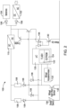
FIG. 2 is a schematic view of a control system for the patient support apparatus shown inFIG. 1 , wherein the control system automatically reassociates a room to the patient support apparatus after the patient support apparatus has been unplugged; -
FIG. 3 is a side elevation view of a wheel assembly of the patient support apparatus shown inFIG. 1 ; -
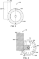
FIG. 4 is a side cut-away view of the wheel assembly of the patient support apparatus taken along the line 4-4 shown inFIG. 3 , wherein a Hall effect sensor is coupled to a base of the wheel assembly, and a magnet disk having a plurality of magnets is coupled to a wheel of the wheel assembly; -
FIG. 5 is a top view of the wheel assembly shown inFIG. 3 showing the Hall effect sensor coupled to the base and the magnet disk coupled to the wheel, wherein an accelerometer is also coupled to the base to measure an angular orientation (β) of a longitudinal axis of the base relative a longitudinal axis that is parallel to at least one frame member of the patient support apparatus, and wherein the longitudinal axis of the base is oriented 0 degrees relative the longitudinal axis that is parallel to the at least one frame member; -
FIG. 6 is a top view of the wheel assembly similar toFIG. 5 , wherein the longitudinal axis of the base is oriented greater than 0 degrees relative the longitudinal axis that is parallel to the at least one frame member; and -
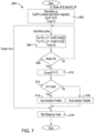
FIG. 7 is a flowchart for a method of automatically reassociating a room to the patient support apparatus after the patient support apparatus has been unplugged. - Referring to
FIG. 1 , adevice 10 in accordance with an embodiment is configured for use in a facility. In an exemplary embodiment, the facility includes a healthcare facility and thedevice 10 includes a medical device. More specifically, in the exemplary embodiment thedevice 10 is apatient support apparatus 12, as illustrated inFIG. 1 . Thepatient support apparatus 12 includes a base 14 having abase frame 16 connected to anintermediate frame 18. An articulateddeck 20 is coupled to theintermediate frame 18. Amattress 22 is carried by the articulateddeck 20 and provides a sleeping surface or support surface 24 configured to receive a patient (not shown). Thebase frame 16 includes a pair of parallelside frame sections 30 coupled by a pair of parallelend frame sections 32 that extend perpendicular to the parallelside frame sections 30.Wheel assemblies 50 extend downward from theside frame sections 30 and enable thepatient support apparatus 12 to be rolled throughout the healthcare facility. Abrake 40 is provided to lock thewheel assemblies 50 to prevent movement of thepatient support apparatus 12. - The
patient support apparatus 12 includes at least one graphical user interface (GUI) 60 that displays various screens to enable a caregiver to operate various functions of thepatient support apparatus 12 by selecting user inputs adjacent to or provided on theGUI 60. For example, in some embodiments, movement of the articulateddeck 20 is controlled via theGUI 60. In some embodiments, thepatient support apparatus 12 is capable of being connected to a local network within the healthcare facility. For example, thepatient support apparatus 12 is wirelessly connected to the local network, in some embodiments. To connect thepatient support apparatus 12 to a local network, thepatient support apparatus 12 is associated with a room in the healthcare facility. For example, in an embodiment, the caregiver associates the room to thepatient support apparatus 12 using theGUI 60. The associated room enables thepatient support apparatus 12 to be wirelessly connected to the correct local network in the healthcare facility. In some embodiments, thepatient support apparatus 12 needs to be reassociated to a room in response to thepatient support apparatus 12 being unplugged, or otherwise powered down, and plugged back in, or otherwise powered. - Referring to
FIG. 2 , acontrol system 100 of thepatient support apparatus 12 is configured to automatically reassociate a room to thepatient support apparatus 12 after thepatient support apparatus 12 has been unplugged. Thecontrol system 100 includes a main AC/DC power source 102 that is configured to be plugged into an outlet of the healthcare facility. Abattery 104 is provided to supply power to thepatient support apparatus 12 in the event that thepower source 102 is unplugged. Aconverter 110 converts the power in thecontrol system 100 to direct current. Thecontrol system 100 includes a plurality ofdiodes 106 andresistors 108. In an exemplary embodiment, theresistors 108 are current limiting resistors. Amicroprocessor 120 is provided having aflash memory 122 and an electrically erasable programmable read only memory (EEPROM) 124. Theflash memory 122 carries instructions that are carried out by theprocessor 120 to perform the steps described herein. TheEEPROM 124 stores data collected by the components of thecontrol system 100 described herein. In an embodiment, themicroprocessor 120 includes a timer. In one embodiment, the timer begins counting from zero is response to the components of thecontrol system 100 being activated. - ] A wake up
switch 130 detects when thepatient support apparatus 12 is moving so that thecontrol system 100 can begin tracking movement data related to thepatient support apparatus 12. For example, anaccelerometer 132 is provided to determine an angular orientation of a wheel (described below) of thewheel assembly 50 about a caster swivel axis of thewheel assembly 50 and aHall effect sensor 134 is provided to detect rotation of the wheel. Abrake switch 136 is further provided to detect whether thewheel assembly 50 is locked. In response to thebrake switch 136 detecting that thewheel assembly 50 is unlocked, thecontrol system 100 begins tracking movement of thepatient support apparatus 12. Data related to the movement of thepatient support apparatus 12 is stored in theEEPROM 124. In response to thebrake switch 136 detecting that thewheel assembly 50 has been locked, thecontrol system 100 determines an end distance that thepatient support apparatus 12 traveled based on the data stored in theEEPROM 124. -
FIGS. 3-5 illustrate anexemplary wheel assembly 50. It will be appreciated that, in some embodiments, only onewheel assembly 50 of thepatient support apparatus 12 is configured with the components described herein. Accordingly, the data processed by thecontrol system 100 is acquired from only the onewheel assembly 50. In other embodiments, any number ofwheel assemblies 50 of thepatient support apparatus 12 include the components described herein. In such an embodiment, thecontrol system 100 processes data from eachwheel assembly 50 having the described components. Thewheel assembly 50 includes a vertically extendingpost 200 that extends from thebase frame 16 toward the floor along anaxis 202. Thewheel assembly 50 is configured to rotate about theaxis 202. Abase 210 extends horizontally from thepost 200 along abase axis 212. In the exemplary embodiment, thebase axis 212 extends substantially perpendicular to theaxis 202. A pair ofadjacent wheels 220 are attached to thebase 210 and configured to rotated relative to the base 210 to roll thepatient support apparatus 12. It will be appreciated that although the exemplary embodiment illustrates twowheels 220, thewheel assembly 50, in some embodiments, includes only onewheel 220. Eachwheel 220 has adiameter 222. - The
Hall effect sensor 134 is coupled to thebase 210 of thewheel assembly 50. Amagnet disk 230 is coupled to one of thewheels 220. Themagnet disk 230 includes a plurality ofmagnets 232 attached thereto. It will be appreciated that themagnet disk 230 can include any number ofmagnets 232. The number ofmagnets 232 provided is factored into the calculations made by thecontrol system 100, as described in more detail below. Themagnets 232 are equally and circumferentially spaced around themagnet disk 230. TheHall effect sensor 134 detects eachmagnet 232 as themagnet 232 passes theHall effect sensor 134 during rotation of thewheel 220 caused by movement of thepatient support apparatus 12. - As illustrated in
FIGs. 5-6 , theaccelerometer 132 is also coupled to thebase 210 of thewheel assembly 50 to measure an angular orientation (β) of thewheel assembly 50 relative to alongitudinal axis 240 that is parallel to at least one frame member of thepatient support apparatus 12. In one embodiment, theaxis 240 is parallel to one of theside frame sections 30 of thebase frame 16. In another embodiment, theaxis 240 is parallel to one ofend frame sections 32 of thebase frame 16. In an exemplary embodiment, theaccelerometer 132 measures the angular orientation (β) of thebase axis 212 of the base 210 relative to thelongitudinal axis 240. That is, as thewheel 220 and the base 210 rotate relative to thepost 200, theaccelerometer 132 measures a degree of the rotation.FIG. 5 illustrates the base 210 in a preset position, wherein the angular orientation (β) is zero degrees.FIG. 6 illustrates the base 210 at an angular orientation (β) that is greater than zero degrees relative to the preset position. As described in more detail below, the angular orientation (β) is a factor in determining an end distance that thepatient support apparatus 12 has moved. - Referring to
FIG. 7 , amethod 300 of automatically re associate a room to thepatient support apparatus 12 after thepatient support apparatus 12 has been unplugged starts in response to themain power source 102 being unplugged and thebrake switch 136 detecting that the brake is deactivated and thewheel assembly 50 is unlocked thereby allowing thepatient support apparatus 12 to be moved. In response, atblock 302, the wake upswitch 130 activates thecontrol system 100. In response to thecontrol system 100 being activated, thecontrol system 100 determines a coefficient of theHall effect sensor 134 using the equation, Coeff=(7r.wheel diam)/(nbr magnets), wherein Coeff is the coefficient, wheel diam equals thediameter 222 of thewheel 220, and nbr magnets equals the number ofmagnets 232 on themagnet disk 230. Initially, when the timer is at zero, a distance moved in the x-direction (X) equals zero and a distance moved in the y-direction (Y) equals zero. Also, in response to thecontrol system 100 waking up, theaccelerometer 132 determines the angular orientation (β) of thewheel 220 and theHall effect sensor 134 detects movement of thewheel 220 by generating pulses that detect movement of themagnets 232. In particular movement of thewheel 220 is detected by detecting an amount of rotation of thewheel 220 about a wheel rotation axis. - At
block 304, thecontrol system 100 calculates a distance moved in the X direction at various counts n using the equation Xn=Xn-1(1+ Coeff cos(β)), wherein X0=0. Thecontrol system 100 also calculates a distance moved in the Y direction at various counts n using the equation Yn=Yn-1(1+ Coeff sin(β)), wherein Y0=0. Thecontrol system 100 then determines atblock 306, whether thebrake switch 136 has been reactivated. If the brake has not been reactivated, thecontrol system 100 continues to detect movement in the X and Y directions, atblock 304. - If the brake has been reactivated, at 310, the
control system 100 the calculates an end distance (D) that thepatient support apparatus 12 has moved using the equation sqr(X2+Y2). Notably, if thepatient support apparatus 12 is moved in a first direction away from an initial location and is then moved in an opposite direction back toward the initial location, thecontrol system 100 calculates the final distance from the initial location as the end distance (D) because the X and Y values will become negative when moving back to the initial location. In response to determining the end distance (D), thecontrol system 100 determines whether the end distance (D) is less than one meter, atblock 312. If the end distance (D) is less than a predetermined distance, atblock 314, the control system activates automatic location, thereby allowing thepatient support apparatus 12 to be automatically reassociated to the initial room that thepatient support apparatus 12 was located in when thepower 102 was unplugged. Accordingly, thepatient support apparatus 12 can be automatically connected to the local network corresponding to the room. If the end distance (D) is greater than the predetermined distance, atblock 316, automatic locating is disabled, thereby requiring the caregiver to manually locate thepatient support apparatus 12 to associate theapparatus 12 to the appropriate room in the healthcare facility. In an exemplary embodiment, the predetermined distance is one meter. Atblock 318, thecontrol system 100 goes back into sleep mode after processing themethod 300. In some embodiments, thecontrol system 100 goes back into sleep mode after a predetermined period of time, for example, one minute. - Embodiments of the invention can be described with reference to the following numbered clauses, with preferred features laid out in the dependent clauses:
- 1. A control system for a device that is positioned in and associated with a room of a facility, the control system comprising:
- a brake switch to determine whether a brake of the device is active,
- a caster swivel sensor caster swivel sensor to determine an angular orientation (β) of a wheel of the device about a caster swivel axis of a wheel assembly of the device,
- a wheel rotation sensor to determine a distance that the wheel of the device has moved, and
- at least one magnet coupled to the wheel of the device to activate the wheel rotation sensor,
- wherein the control system wakes up when at least one of the brake is deactivated and the device is unplugged,
- wherein, in response to the device waking up, the caster swivel sensor determines the angular orientation (β) of the wheel of the device and the wheel rotation sensor detects movement of the wheel based on detection of the at least one magnet,
- wherein, in response to the brake being reactivated, the control system determines an end distance that the device has moved based on the detected angular orientation (β) of the wheel and the detected movement of the wheel, and
- wherein, if the device has moved less than a predetermined distance, the control system automatically reassociates the device to the same room.
- 2. The control system of
clause 1, wherein, if the device has moved more than the predetermined distance, the control system automatically notifies a user to associate a new room to the device. - 3. The control system of clause 2, wherein the predetermined distance is one meter.
- 4. The control system of any preceding clause, wherein the caster swivel sensor determines the angular orientation (β) of the wheel relative to a preset position of the wheel.
- 5. The control system of
clause 4, wherein the wheel is attached to a base that rotates relative to a post coupled to a frame of the device, wherein, in the preset position, a longitudinal axis of the base is parallel to a side of the frame of the device. - 6. The control system of clause 5, wherein a coefficient (Coeff) of the wheel rotation sensor is equal to (π times a diameter of the wheel)/(a number of magnets on the wheel).
- 7. The control system of clause 6, wherein an end distance (D) that the device has moved equals sqr(X2+Y2), wherein Xn=Xn-1(1+ Coeff cos(β)) and Yn=Yn-1(1+ Coeff sin(β)), wherein X is a distance in the x direction and Y is a distance in the y direction.
- 8. The control system of any preceding clause, wherein the control system enters a sleep mode if movement of the wheel is not detected for a predetermined period of time.
- 9. The control system of clause 8, wherein the predetermined period of time is one minute.
- 10. The control system of either clause 8 or clause 9, wherein, after returning to the sleep mode, the control system wakes up in response to the wheel rotation sensor detecting movement of the wheel.
- 11. The control system of any preceding clause, wherein the control system enters a sleep mode, after the device is automatically reassociated to the same room.
- 12. The control system of any preceding clause, wherein the device is reassociated to the room of the facility to connect the device to a wireless network in the room.
- 13. The control system of any preceding clause, wherein the facility includes a healthcare facility and the device includes a medical device.
- 14. The control system of clause 13, wherein the medical device is a patient support apparatus.
- 15. The control system of any preceding clause, wherein the wheel is attached to a base that rotates relative to a post coupled to a frame of the device, wherein the caster swivel sensor is attached to the base.
- 16. The control system of clause 15, wherein the wheel rotation sensor is coupled to the base.
- 17. The control system of any preceding clause, wherein the at least one magnet includes a plurality of magnets.
- 18. The control system of clause 17, wherein the plurality of magnets are equally circumferentially spaced around the wheel.
- 19. The control system of any preceding clause, wherein the caster swivel sensor includes an accelerometer.
- 20. The control system of any preceding clause, wherein the wheel rotation sensor includes a Hall effect sensor.
- 21. A method for automatically reassociating a room in a facility to a device that is moved from a position in the room, wherein the device is associated to the room of the facility prior to being moved, the method comprising:
- waking up a control system when at least one of a brake of the device is deactivated and the device is unplugged,
- in response to the device waking up, determining, with an accelerometer, an angular orientation (β) of a wheel of the device about a caster swivel axis of a wheel assembly of the device and detecting, with a Hall effect sensor, movement of the wheel based on detection of at least one magnet coupled to the wheel, and
- in response to the brake being reactivated, determining an end distance that the device has moved based on the detected angular orientation (β) of the wheel and the detected movement of the wheel,
- wherein, if the device has moved less than a predetermined distance, automatically reassociating the device to the same room.
- 22. The method of clause 21, further comprising automatically notifying a user to associate a new room to the device, if the device has moved more than the predetermined distance.
- 23. The method of
clause 22, wherein the predetermined distance is one meter. - 24. The method of any one of clauses 21 to 23, further comprising determining, with the accelerometer, the angular orientation (β) of the wheel relative to a preset position of the wheel.
- 25. The method of clause 24, wherein the wheel is attached to a base that rotates relative to a post coupled to a frame of the device, wherein, in the preset position, a longitudinal axis of the base is parallel to a side of the frame of the device.
- 26. The method of clause 25, wherein a coefficient (Coeff) of the Hall effect sensor is equal to (π times a diameter of the wheel)/(a number of magnets on the wheel).
- 27. The method of clause 26, wherein an end distance (D) that the device has moved equals sqr(X2+Y2), wherein Xn=Xn-1(1+ Coeff cos(β)) and Yn=Yn-1(1+ Coeff sin(β)), wherein X is a distance in the x direction and Y is a distance in the y direction.
- 28. The method of any one of clauses 21 to 27, further comprising activating a sleep mode if movement of the wheel is not detected for a predetermined period of time.
- 29. The method of clause 28, wherein the predetermined period of time is one minute.
- 30. The method of either clause 28 or 29, further comprising waking up the control system, after returning to the sleep mode, in response to the Hall effect sensor detecting movement of the wheel.
- 31. The method of any one of clauses 21 to 30, wherein the control system enters a sleep mode, after the device is automatically reassociated to the same room.
- 32. The method of any one of clauses 21 to 31, further comprising reassociating the device to the room of the facility to connect the device to a wireless network in the room.
- 33. The method of any one of clauses 21 to 32, wherein the facility includes a healthcare facility and the device includes a medical device.
- 34. The method of clause 33, wherein the medical device is a patient support apparatus.
- 35. The method of any one of clauses 21 to 34, wherein the wheel is attached to a base that rotates relative to a post coupled to a frame of the device, wherein the accelerometer is attached to the base.
- 36. The method of clause 35, wherein the Hall effect sensor is coupled to the base.
- 37. The method of clause 36, wherein the at least one magnet includes a plurality of magnets.
- 38. The method of clause 37, wherein the plurality of magnets are equally circumferentially spaced around the wheel.
- 39. A control system for a patient support apparatus that is positioned in and associated with a room of a healthcare facility, the control system comprising:
- an accelerometer to determine an angular orientation (β) of a wheel of the bed about a caster swivel axis of a wheel assembly of the bed, and
- a Hall effect sensor to determine a distance that the wheel of the bed has moved by detecting movement of at least one magnet coupled to the wheel,
- wherein, in response to the bed being moved, the control system determines an end distance that the bed has moved based on a detected angular orientation (β) of the wheel, as measured by the accelerometer, and movement of the wheel, as detected by the Hall effect sensor, and
- wherein, if the bed has moved less than a predetermined distance, the bed is automatically reassociated to the same room to enable connection to a wireless network in the room.
Claims (15)
- A control system for a device that is positioned in and associated with a room of a facility, the control system comprising:a brake switch to determine whether a brake of the device is active,a caster swivel sensor caster swivel sensor to determine an angular orientation (β) of a wheel of the device about a caster swivel axis of a wheel assembly of the device,a wheel rotation sensor to determine a distance that the wheel of the device has moved, andat least one magnet coupled to the wheel of the device to activate the wheel rotation sensor,wherein the control system wakes up when at least one of the brake is deactivated and the device is unplugged,wherein, in response to the device waking up, the caster swivel sensor determines the angular orientation (β) of the wheel of the device and the wheel rotation sensor detects movement of the wheel based on detection of the at least one magnet,wherein, in response to the brake being reactivated, the control system determines an end distance that the device has moved based on the detected angular orientation (β) of the wheel and the detected movement of the wheel, andwherein, if the device has moved less than a predetermined distance, the control system automatically reassociates the device to the same room.
- The control system of claim 1, wherein, if the device has moved more than the predetermined distance, the control system automatically notifies a user to associate a new room to the device, and wherein preferably the predetermined distance is one meter.
- The control system of either claim 1 or claim 2, wherein the caster swivel sensor determines the angular orientation (β) of the wheel relative to a preset position of the wheel.
- The control system of claim 3, wherein the wheel is attached to a base that rotates relative to a post coupled to a frame of the device, wherein, in the preset position, a longitudinal axis of the base is parallel to a side of the frame of the device.
- The control system of claim 4, wherein a coefficient (Coeff) of the wheel rotation sensor is equal to (π times a diameter of the wheel)/(a number of magnets on the wheel).
- The control system of claim 5, wherein an end distance (D) that the device has moved equals sqr(X2+Y2), wherein Xn=Xn-1(1+ Coeff cos(β)) and Yn=Yn-1(1+ Coeff sin(β)), wherein X is a distance in the x direction and Y is a distance in the y direction.
- The control system of any preceding claim, wherein the control system enters a sleep mode if movement of the wheel is not detected for a predetermined period of time, and wherein preferably the predetermined period of time is one minute.
- The control system of claim 7, wherein, after returning to the sleep mode, the control system wakes up in response to the wheel rotation sensor detecting movement of the wheel.
- The control system of any preceding claim, wherein the control system enters a sleep mode, after the device is automatically reassociated to the same room.
- The control system of any preceding claim, wherein the device is reassociated to the room of the facility to connect the device to a wireless network in the room.
- The control system of any preceding claim, wherein the wheel is attached to a base that rotates relative to a post coupled to a frame of the device, wherein the caster swivel sensor is attached to the base.
- The control system of claim 11, wherein the wheel rotation sensor is coupled to the base.
- The control system of any preceding claim, wherein the at least one magnet includes a plurality of magnets.
- The control system of claim 13, wherein the plurality of magnets are equally circumferentially spaced around the wheel.
- The control system of any preceding claim, wherein the caster swivel sensor includes an accelerometer and/or the wheel rotation sensor includes a Hall effect sensor.
Applications Claiming Priority (1)
| Application Number | Priority Date | Filing Date | Title |
|---|---|---|---|
| US202363611360P | 2023-12-18 | 2023-12-18 |
Publications (1)
| Publication Number | Publication Date |
|---|---|
| EP4574124A1 true EP4574124A1 (en) | 2025-06-25 |
Family
ID=93852945
Family Applications (1)
| Application Number | Title | Priority Date | Filing Date |
|---|---|---|---|
| EP24218593.2A Pending EP4574124A1 (en) | 2023-12-18 | 2024-12-10 | Intra-room bed movement monitoring for wirelessly connected bed |
Country Status (2)
| Country | Link |
|---|---|
| US (1) | US20250195304A1 (en) |
| EP (1) | EP4574124A1 (en) |
Citations (4)
| Publication number | Priority date | Publication date | Assignee | Title |
|---|---|---|---|---|
| US20110162141A1 (en) * | 2005-12-19 | 2011-07-07 | Stryker Corporation | Hospital bed |
| US20190358997A1 (en) * | 2018-05-25 | 2019-11-28 | Chun-Tao Chou | Smart wheel |
| US20200268579A1 (en) * | 2019-02-26 | 2020-08-27 | Hill-Rom Services, Inc. | Bed interface for manual location |
| US20230277397A1 (en) * | 2022-03-07 | 2023-09-07 | Hill-Rom Services, Inc. | Patient support apparatus having motorized wheels |
Family Cites Families (8)
| Publication number | Priority date | Publication date | Assignee | Title |
|---|---|---|---|---|
| US3893330A (en) * | 1972-12-18 | 1975-07-08 | Data Systems Inc | Surface friction testing |
| US7835856B2 (en) * | 2004-10-25 | 2010-11-16 | General Motors Llc | Method and system for telematics location sensing |
| US8373110B2 (en) * | 2009-05-26 | 2013-02-12 | Honeywell International Inc. | System and method for linear and angular measurements of a moving object |
| US10004651B2 (en) * | 2012-09-18 | 2018-06-26 | Stryker Corporation | Patient support apparatus |
| KR102243179B1 (en) * | 2019-03-27 | 2021-04-21 | 엘지전자 주식회사 | Moving robot and control method thereof |
| US12080420B2 (en) * | 2020-05-29 | 2024-09-03 | Hill-Rom Services, Inc. | Wireless location learning |
| US11695625B2 (en) * | 2021-07-15 | 2023-07-04 | International Business Machines Corporation | Location-based dynamic grouping of IoT devices |
| US20240402210A1 (en) * | 2023-06-02 | 2024-12-05 | Allegro Microsystems, Llc | Sensor having low power movement detection |
-
2024
- 2024-11-19 US US18/952,276 patent/US20250195304A1/en active Pending
- 2024-12-10 EP EP24218593.2A patent/EP4574124A1/en active Pending
Patent Citations (4)
| Publication number | Priority date | Publication date | Assignee | Title |
|---|---|---|---|---|
| US20110162141A1 (en) * | 2005-12-19 | 2011-07-07 | Stryker Corporation | Hospital bed |
| US20190358997A1 (en) * | 2018-05-25 | 2019-11-28 | Chun-Tao Chou | Smart wheel |
| US20200268579A1 (en) * | 2019-02-26 | 2020-08-27 | Hill-Rom Services, Inc. | Bed interface for manual location |
| US20230277397A1 (en) * | 2022-03-07 | 2023-09-07 | Hill-Rom Services, Inc. | Patient support apparatus having motorized wheels |
Also Published As
| Publication number | Publication date |
|---|---|
| US20250195304A1 (en) | 2025-06-19 |
Similar Documents
| Publication | Publication Date | Title |
|---|---|---|
| US11484223B2 (en) | Person support apparatuses with motion monitoring | |
| US10127788B2 (en) | Estimation and monitoring of patient torso angle | |
| US10660544B2 (en) | Self-compensating bed scale system for removable components | |
| CN209548267U (en) | Patient support apparatus with urine drainage bag lock-in feature | |
| EP3703074B1 (en) | Patient bed with interface for manual input of its location | |
| US10898400B2 (en) | Person support apparatuses with load cells | |
| US20230067526A1 (en) | Patient support apparatus with automatic exit detection modes of operation | |
| US20120029879A1 (en) | Above bed sensor | |
| JP3093745B2 (en) | Sleeper equipment | |
| US20250285523A1 (en) | Hospital bed exit detection method and system | |
| JP2008282219A (en) | Bed leaving detection system and method | |
| US20210369522A1 (en) | Patient apparatus with touchscreen | |
| JP2004201758A (en) | Roll-over monitoring device, its system, and bedsore prevention method | |
| CN113613563B (en) | Systems and methods for mobile radiography deployment | |
| US20250195304A1 (en) | Intra-room bed movement monitoring for wirelessly connected bed | |
| US11344267B2 (en) | Patient support apparatus with X-ray cassette positioning | |
| CN112466089B (en) | System and method for monitoring positional stability | |
| EP4233712A1 (en) | Monitor to detect a patient's sleep state and movement | |
| JP2000241561A (en) | Bed state detection device and method | |
| KR20190080657A (en) | System for monitoring activity on wheelchair and method therefor | |
| WO2024049937A2 (en) | Hospital bed alert light management | |
| US20220233378A1 (en) | Patient Compliance Monitoring System | |
| JP2021146120A (en) | Information detection device, monitoring system and information detection method | |
| CN118593262A (en) | Intelligent protective bed | |
| CA2986287A1 (en) | Hospital bed exit detection, height limiting and tare weight recalibrating systems and methods |
Legal Events
| Date | Code | Title | Description |
|---|---|---|---|
| PUAI | Public reference made under article 153(3) epc to a published international application that has entered the european phase |
Free format text: ORIGINAL CODE: 0009012 |
|
| STAA | Information on the status of an ep patent application or granted ep patent |
Free format text: STATUS: THE APPLICATION HAS BEEN PUBLISHED |
|
| AK | Designated contracting states |
Kind code of ref document: A1 Designated state(s): AL AT BE BG CH CY CZ DE DK EE ES FI FR GB GR HR HU IE IS IT LI LT LU LV MC ME MK MT NL NO PL PT RO RS SE SI SK SM TR |
|
| STAA | Information on the status of an ep patent application or granted ep patent |
Free format text: STATUS: REQUEST FOR EXAMINATION WAS MADE |
|
| 17P | Request for examination filed |
Effective date: 20251212 |
|
| GRAP | Despatch of communication of intention to grant a patent |
Free format text: ORIGINAL CODE: EPIDOSNIGR1 |
|
| STAA | Information on the status of an ep patent application or granted ep patent |
Free format text: STATUS: GRANT OF PATENT IS INTENDED |
|
| RIC1 | Information provided on ipc code assigned before grant |
Ipc: A61G 7/018 20060101AFI20260401BHEP Ipc: A61G 7/05 20060101ALI20260401BHEP Ipc: G16H 40/20 20180101ALI20260401BHEP |
|
| INTG | Intention to grant announced |
Effective date: 20260429 |