EP4574036A1 - Applicator and applicator assembly - Google Patents
Applicator and applicator assembly Download PDFInfo
- Publication number
- EP4574036A1 EP4574036A1 EP24221841.0A EP24221841A EP4574036A1 EP 4574036 A1 EP4574036 A1 EP 4574036A1 EP 24221841 A EP24221841 A EP 24221841A EP 4574036 A1 EP4574036 A1 EP 4574036A1
- Authority
- EP
- European Patent Office
- Prior art keywords
- applicator
- shuttle
- assembly
- needle
- coupled
- Prior art date
- Legal status (The legal status is an assumption and is not a legal conclusion. Google has not performed a legal analysis and makes no representation as to the accuracy of the status listed.)
- Pending
Links
Images











Classifications
-
- A—HUMAN NECESSITIES
- A61—MEDICAL OR VETERINARY SCIENCE; HYGIENE
- A61B—DIAGNOSIS; SURGERY; IDENTIFICATION
- A61B5/00—Measuring for diagnostic purposes; Identification of persons
- A61B5/145—Measuring characteristics of blood in vivo, e.g. gas concentration or pH-value ; Measuring characteristics of body fluids or tissues, e.g. interstitial fluid or cerebral tissue
- A61B5/14532—Measuring characteristics of blood in vivo, e.g. gas concentration or pH-value ; Measuring characteristics of body fluids or tissues, e.g. interstitial fluid or cerebral tissue for measuring glucose, e.g. by tissue impedance measurement
-
- A—HUMAN NECESSITIES
- A61—MEDICAL OR VETERINARY SCIENCE; HYGIENE
- A61B—DIAGNOSIS; SURGERY; IDENTIFICATION
- A61B5/00—Measuring for diagnostic purposes; Identification of persons
- A61B5/145—Measuring characteristics of blood in vivo, e.g. gas concentration or pH-value ; Measuring characteristics of body fluids or tissues, e.g. interstitial fluid or cerebral tissue
- A61B5/14503—Measuring characteristics of blood in vivo, e.g. gas concentration or pH-value ; Measuring characteristics of body fluids or tissues, e.g. interstitial fluid or cerebral tissue invasive, e.g. introduced into the body by a catheter or needle or using implanted sensors
-
- A—HUMAN NECESSITIES
- A61—MEDICAL OR VETERINARY SCIENCE; HYGIENE
- A61B—DIAGNOSIS; SURGERY; IDENTIFICATION
- A61B5/00—Measuring for diagnostic purposes; Identification of persons
- A61B5/145—Measuring characteristics of blood in vivo, e.g. gas concentration or pH-value ; Measuring characteristics of body fluids or tissues, e.g. interstitial fluid or cerebral tissue
- A61B5/1468—Measuring characteristics of blood in vivo, e.g. gas concentration or pH-value ; Measuring characteristics of body fluids or tissues, e.g. interstitial fluid or cerebral tissue using chemical or electrochemical methods, e.g. by polarographic means
- A61B5/1473—Measuring characteristics of blood in vivo, e.g. gas concentration or pH-value ; Measuring characteristics of body fluids or tissues, e.g. interstitial fluid or cerebral tissue using chemical or electrochemical methods, e.g. by polarographic means invasive, e.g. introduced into the body by a catheter
-
- A—HUMAN NECESSITIES
- A61—MEDICAL OR VETERINARY SCIENCE; HYGIENE
- A61B—DIAGNOSIS; SURGERY; IDENTIFICATION
- A61B5/00—Measuring for diagnostic purposes; Identification of persons
- A61B5/15—Devices for taking samples of blood
- A61B5/150007—Details
- A61B5/150206—Construction or design features not otherwise provided for; manufacturing or production; packages; sterilisation of piercing element, piercing device or sampling device
-
- A—HUMAN NECESSITIES
- A61—MEDICAL OR VETERINARY SCIENCE; HYGIENE
- A61B—DIAGNOSIS; SURGERY; IDENTIFICATION
- A61B5/00—Measuring for diagnostic purposes; Identification of persons
- A61B5/68—Arrangements of detecting, measuring or recording means, e.g. sensors, in relation to patient
- A61B5/6846—Arrangements of detecting, measuring or recording means, e.g. sensors, in relation to patient specially adapted to be brought in contact with an internal body part, i.e. invasive
- A61B5/6847—Arrangements of detecting, measuring or recording means, e.g. sensors, in relation to patient specially adapted to be brought in contact with an internal body part, i.e. invasive mounted on an invasive device
- A61B5/6848—Needles
-
- A—HUMAN NECESSITIES
- A61—MEDICAL OR VETERINARY SCIENCE; HYGIENE
- A61B—DIAGNOSIS; SURGERY; IDENTIFICATION
- A61B5/00—Measuring for diagnostic purposes; Identification of persons
- A61B5/68—Arrangements of detecting, measuring or recording means, e.g. sensors, in relation to patient
- A61B5/6846—Arrangements of detecting, measuring or recording means, e.g. sensors, in relation to patient specially adapted to be brought in contact with an internal body part, i.e. invasive
- A61B5/6847—Arrangements of detecting, measuring or recording means, e.g. sensors, in relation to patient specially adapted to be brought in contact with an internal body part, i.e. invasive mounted on an invasive device
- A61B5/685—Microneedles
-
- A—HUMAN NECESSITIES
- A61—MEDICAL OR VETERINARY SCIENCE; HYGIENE
- A61B—DIAGNOSIS; SURGERY; IDENTIFICATION
- A61B90/00—Instruments, implements or accessories specially adapted for surgery or diagnosis and not covered by any of the groups A61B1/00 - A61B50/00, e.g. for luxation treatment or for protecting wound edges
- A61B90/03—Automatic limiting or abutting means, e.g. for safety
- A61B2090/033—Abutting means, stops, e.g. abutting on tissue or skin
-
- A—HUMAN NECESSITIES
- A61—MEDICAL OR VETERINARY SCIENCE; HYGIENE
- A61B—DIAGNOSIS; SURGERY; IDENTIFICATION
- A61B2560/00—Constructional details of operational features of apparatus; Accessories for medical measuring apparatus
- A61B2560/06—Accessories for medical measuring apparatus
- A61B2560/063—Devices specially adapted for delivering implantable medical measuring apparatus
-
- A—HUMAN NECESSITIES
- A61—MEDICAL OR VETERINARY SCIENCE; HYGIENE
- A61B—DIAGNOSIS; SURGERY; IDENTIFICATION
- A61B2562/00—Details of sensors; Constructional details of sensor housings or probes; Accessories for sensors
- A61B2562/12—Manufacturing methods specially adapted for producing sensors for in-vivo measurements
Definitions
- the present invention relates to an applicator and an applicator assembly.
- a blood glucose meter that the user uses directly to monitor his or her own biometric data, such as a blood glucose level (blood glucose level).
- a blood-collection type blood glucose meter requires a blood-collecting behavior of a user, it may be difficult to immediately monitor a hypoglycemic state.
- a CGMS may increase the inconvenience to the user when used but is increasingly being used in that it can relatively immediately monitor biometric data.
- One of embodiments of the present invention is directed to providing an applicator and an applicator assembly, which are capable of increasing user convenience when a sensing device is attached to a body.
- Another one of embodiments of the present invention is directed to providing an applicator and an applicator assembly, which are capable of attaching a sensing device to a body and then reducing environmental pollution when the applicator is discarded.
- an applicator including an insertion unit assembly that includes a needle and moves the needle in each of a first direction and a second direction that is a direction opposite to the first direction, an applicator body in which the insertion unit assembly is disposed, and an operation part that is coupled to the insertion unit assembly in the applicator body and allows the needle to move in the first direction, wherein the applicator body includes a base frame, a top case which is seated on the base frame to cover at least a part of the base frame and of which at least a part is formed of a molded pulp, and a top case restriction member coupled to the base frame to restrict the top case to the base frame.
- an applicator assembly including a sensing device, and an applicator detachably coupled to the sensing device, wherein the applicator includes an applicator body covering the sensing device, an insertion unit assembly that is disposed in the applicator body and moves at least a part of the sensing device in a first direction, and an operation part that is disposed in the applicator body, coupled to the insertion unit assembly, and allows the at least a part of the sensing device to move in the first direction, and the applicator body includes a base frame in which a recess is formed in a lower surface thereof, a top case which is seated on the base frame to cover at least a part of the base frame and of which at least a part is formed of a molded pulp, and a top case restriction member coupled to the base frame to restrict the top case to the base frame.
- Coupled is used as a concept that includes not only a case in which components are physically in direct contact with each other in a contact relationship between the components, but also a case in which another component is interposed between the components and the components are each in contact with another component.
- the term “detaching” is used as a concept that means that two or more components coupled in a state in which no relative movement occurs therebetween move relatively with respect to each other by a user's manipulation or the like within a normal usage range.
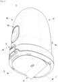
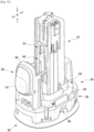
- FIG. 1 is a schematic perspective view illustrating an applicator assembly according to one embodiment of the present invention.
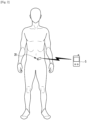
- FIG. 2 is a schematic view illustrating a state in which a sensing device of the applicator assembly is attached to a user's body according to one embodiment of the present invention.
- FIG. 3 is a schematic view illustrating a state in which a sensor unit and a base unit of the sensing device are not coupled yet.
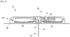
- FIG. 4 is a schematic view illustrating a state in which the sensor unit and the base unit are coupled.
- FIGS. 5 and 6 are schematic views illustrating a state in which the sensor unit is disassembled.
- FIG. 7 is a schematic view illustrating a state in which a needle is coupled to the sensor unit.
- FIG. 1 is a schematic perspective view illustrating an applicator assembly according to one embodiment of the present invention.
- FIG. 2 is a schematic view illustrating a state in which a sensing device of the applicator assembly is attached to a user's body according to one
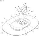
- FIG. 8 is a schematic view illustrating the base unit of the sensing device.
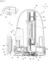
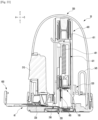
- FIG. 9 is a schematic cross-sectional view along line I-I' in FIG. 1 .
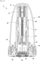
- FIG. 10 is a schematic cross-sectional view along line II-II' in FIG. 1 .
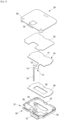
- FIG. 11 is a schematic view illustrating a state in which an applicator assembly is disassembled according to one embodiment of the present invention.
- FIG. 12 is a schematic view illustrating a state in which a base frame, a locking hook, and a moving tab among components of the applicator are disassembled.
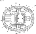
- FIG. 13 is a schematic top view illustrating a state in which the base frame and the locking hook of the applicator are coupled.
- FIGS. 14A, 14B, and 14C are top views illustrating a state in which the base frame and the locking hook of the applicator assembly are coupled according to one embodiment of the present invention and sequentially show operation processes of the locking hook due to the movement of an operation part.
- FIGS. 15 and 16 are schematic views illustrating a middle frame of the applicator.
- FIG. 17 is a schematic view illustrating the operation part.
- FIG. 18 is a schematic view illustrating a state in which an insertion unit assembly of the applicator is disassembled.
- FIG. 19 is a schematic view illustrating a part of an intemal structure of the applicator assembly according to one embodiment of the present invention and is a schematic view illustrating a state in which the operation part is positioned at a deactivation position.
- FIGS. 20 is a schematic view illustrating a part of the internal structure of the applicator assembly according to one embodiment of the present invention and is a schematic view illustrating a state in which the operation part is positioned at an activation position.
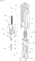
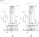
- FIGS. 21A and 21B are schematic views illustrating a part of the intemal structure of the applicator assembly according to one embodiment of the present invention and are schematic views illustrating the state in which the operation part is positioned at the deactivation position and the state in which the operation part is positioned at the activation position.
- FIG. 22 is a schematic view illustrating an operation prevention part and a protective sheet applied to the present embodiment.
- FIGS. 23 to 27 are schematic views illustrating a method of manipulating the applicator assembly according to one embodiment of the present invention, in which FIGS. 23 , 24 , and 26 are schematic cross-sectional views along line I-I' in FIG. 1 , and FIGS. 25 and 27 are schematic cross-sectional views along line II-II' in FIG. 1 .
- an applicator assembly 10 includes a sensing device 20, an applicator 30, an operation prevention part 40, and a protective sheet 50.
- the sensing device 20 may detect biometric data at each of different time points while attached to a user's skin and wirelessly transmit detected data to an external terminal 5.
- the biometric data may be a blood glucose level, but the scope of the present invention is not limited thereto.
- the different time points may be, for example, at least three or more time points with substantially the same cycle, but the scope of the present invention is not limited thereto.
- the external terminal 5 may be any of various devices capable of receiving detected data of the sensing device 20, such as a user's portable terminal, a dedicated medical device, a PC, a server, and the like.
- the sensing device 20 includes a sensor unit 100 and a base unit 200.
- the sensing device 20 in a form in which the sensor unit 100 and the base unit 200 are spaced apart from each other within the applicator 30 to be described below may be provided to the user.
- the sensor unit 100 and the base unit 200 of the sensing device 20 may be coupled.
- the sensing device 20 may be detached from the applicator 30 and then attached to the user's body.
- the concept of the sensing device 20 includes both a state in which the sensor unit 100 and the base unit 200 are spaced apart from each other and a state in which the sensor unit 100 and the base unit 200 are coupled.
- the sensing device 20 includes the sensor unit 100 and the base unit 200 that are disposed to be spaced apart from each other in the applicator 30 and are coupled by the user's manipulation of the applicator 30.
- the sensor unit 100 and the base unit 200 may be disposed in a coupled form in the applicator 30 and moved in a first direction (see a direction illustrated in FIGS. 19 , 20 , and 23 to 27 ) by the user's manipulation of the applicator 30 while maintaining the coupled state to be attached to the user's skin and detached from the applicator 30 while maintaining the coupled state.
- the sensor unit 100 may be inserted into the user's skin to detect biometric data and generate a signal.
- the sensor unit 100 includes a sensor 110, a sensor unit housing 120, a sensor adhesive part 149, and an adhesive pad 152.
- the sensor 110 may be inserted into the user's skin to detect biometric data.
- the sensor 110 includes a sensor body 111, a connection portion 112, a middle portion 113, an extension 114, and an insertion portion 116.
- the sensor body 111 may be disposed inside the sensor unit housing 120 to be described below.
- the connection portion 112 may extend from one side of the sensor body 111 to connect the sensor body 111 to the middle portion 113.
- the connection portion 112 may be formed so that the sensor body 111 and the middle portion 113 are disposed on different planes.
- the middle portion 113 may extend from one side of the connection portion 112 to connect the connection portion 112 to the insertion portion 116.
- the middle portion 113 may include the extension 114 protruding from the connection portion 112 to one side thereof.
- the insertion portion 116 may be connected to the extension 114 and inserted into the user's skin.
- the insertion portion 116 may be formed in a relatively thin and long probe shape to be smoothly inserted into the user's skin.
- the sensor body 111, the connection portion 112, the middle portion 113, and the insertion portion 116 may be manufactured in a flat shape, and then the connection portion 112 may be bent. Due to the bending of the connection portion 112, the middle portion 113 and the insertion portion 116 may be disposed on different planes from the sensor body 111, but the scope of the present invention is not limited thereto.
- FIGS. 5 and 6 illustrate that the middle portion 113 and the insertion portion 116 are disposed to be coplanar and the middle portion 113 is disposed vertically with the sensor body 111, but an angle between the middle portion 113 and the sensor body 111 or an angle between the insertion portion 116 and the sensor body 111 may be changed in various ways.
- conductive traces electrically connected to electrodes of the sensor body 111 may be disposed on the connection portion 112, the middle portion 113, and the insertion portion 116.
- the sensor unit housing 120 accommodates at least a part of the sensor 110 therein.
- the sensor body 111, the connection portion 112, and the middle portion 113 of the sensor 110 may be disposed inside the sensor unit housing 120, and at least a part of the insertion portion 116 of the sensor 110 may protrude from the sensor unit housing 120.
- the sensor unit housing 120 includes a housing base 121 and a housing cap 134.
- the housing base 121 includes a base part 122 that supports the sensor body 111 and a boss 127 protruding from a surface of the base part 122.
- a through hole 124 may be formed in one side of the base part 122.
- An electrical contact part 225 to be described below may be inserted into the through hole 124.
- a housing base hole 128 may be formed in the boss 127.
- the insertion portion 116 and a needle 485 to be described below may be inserted into the housing base hole 128.
- a detent protrusion 125 may be formed at an edge of the base part 122. When the housing base 121 and a housing cap 134 to be described below are coupled, the detent protrusion 125 may be inserted into a detent groove 139 of the housing cap 134.
- the housing cap 134 may be coupled to the housing base 121 to cover the sensor body 111.
- a housing cap hole 135 may be formed at one side of the housing cap 134.
- the housing cap hole 135 is connected to the housing base hole 128 of the housing base 121. Accordingly, the needle 485 may pass through the housing cap hole 135 and the housing base hole 128 and protrude outward from the sensor unit housing 120.
- the detent groove 139 may be formed in the housing cap 134. When the housing base 121 and the housing cap 134 are coupled, the detent protrusion 125 of the housing base 121 may be inserted into the detent groove 139.
- a sensor unit groove 138 may be formed in the housing cap 134.
- a push protrusion 442 of a shuttle 431 may be inserted into the sensor unit groove 138.
- the sensor unit groove 138 is formed to protrude from an inner surface of the housing cap 134 facing the housing base 121.
- a region in which the sensor unit groove 138 protrudes from the inner surface of the housing cap 134 may be inserted into a housing engagement portion of the housing base 121.
- a retention protrusion 136 may be formed on the inner surface of the housing cap 134 facing the housing base 121. The retention protrusion 136 may be disposed so that an end portion faces the middle portion 113 inserted into the housing base hole 128 to restrict the movement of the middle portion 113 of the sensor 110.
- the insertion portion 116 of the sensor 110 may stably maintain a state of protruding a predetermined length from the sensor unit housing 120.
- the insertion portion 116 of the sensor 110 may maintain a state of being inserted into the user's skin to a predetermined depth without moving backward from the user's skin while inserted into the user's skin.
- the sensor adhesive part 149 may be disposed between the housing base 121 and the sensor body 111 to attach the sensor body 111 to the housing base 121.
- the sensor adhesive part 149 may be formed in the form of a double-sided tape of which both surfaces have adhesive properties, but the scope of the present invention is not limited thereto.
- a sensor adhesive part opening 150 may be formed in a central portion of the sensor adhesive part 149.
- the electrical contact part 225 to be described below may be inserted into the sensor adhesive part opening 150.
- the adhesive pad 152 may be disposed between the housing cap 134 and the sensor body 111 to attach the sensor body 111 to the housing cap 134.
- the adhesive pad 152 may be formed in the form of a double-sided tape of which both surfaces have adhesive properties, but the scope of the present invention is not limited thereto.
- An adhesive pad engagement portion may be formed on the adhesive pad 152. Through the adhesive pad engagement portion, the sensor unit groove 138 protruding to the inner surface of the housing cap 134 may be inserted into the housing engagement portion of the housing base 121.
- the base unit 200 may be coupled to the sensor unit 100 and attached to the user's skin.
- the base unit 200 may be electrically connected to the sensor unit 100 to process the biometric data measured by the sensor unit 100 and transmit the processed biometric data to the external terminal 5.
- the base unit 200 includes a base unit housing 210, an electronic component, an adhesive layer 230, a protective sheet 240, and an adhesive part 250.
- the base unit housing 210 may be coupled to the sensor unit housing 120.
- the base unit housing 210 may form an overall exterior of the base unit 200.
- An insertion hole 211 may be formed in the base unit housing 210.
- the insertion hole 211 may be formed in a form into which the boss 127 of the sensor unit 100 may be inserted so that at least a part of the insertion portion 116 of the sensor 110 may be inserted into the insertion hole 211.
- a mounting part 212 which has a region in which the sensor unit housing 120 is accommodated, may be formed in the base unit housing 210.
- the mounting part 212 includes a base unit recess 213.
- the sensor unit housing 120 may be coupled to the base unit recess 213.
- a housing groove 217 may be formed in the base unit housing 210.
- the electrical contact part 225 may be formed in the base unit housing 210.
- the electrical contact part 225 may be in contact with the sensor body 111 after passing through the through hole 124 and the sensor adhesive part opening 150 of the sensor unit 100 when the sensor unit 100 is coupled to the base unit 200.
- the electrical contact part 225 may be formed in a form that may be elastically deformed for stable contact with the sensor body 111.
- the electrical contact part 225 may be electrically connected to a substrate 223 to be described below.
- the electronic component is disposed inside the base unit housing 210.
- the electronic component may include the substrate 223, the electrical contact part 225 in contact with the sensor 110, a battery 228, and various chips.
- the chips may be disposed on the substrate 223.
- the chip may include a processor chip for processing signals and a communication chip for communicating with the external terminal 5.
- the adhesive layer 230 may be disposed on one surface of the base unit housing 210 to couple the sensor unit housing 120 with the base unit housing 210.
- the adhesive layer 230 may seal a gap between the sensor unit housing 120 and the base unit housing 210 to prevent moisture or foreign substances from being introduced into the electrical contact part 225.
- Adhesive layer holes 231 and 232 may be formed in the adhesive layer 230. Since the adhesive layer hole 231 is connected to the insertion hole 211, the needle 485 and the insertion portion 116 of the sensor 110 may pass through the adhesive layer hole 231. The electrical contact part 225 may pass through the adhesive layer hole 232.
- the adhesive layer 230 may be formed in the form of a double-sided tape of which both surfaces have adhesive properties.
- the protective sheet 240 may cover the adhesive layer 230 to prevent the adhesive properties of the adhesive layer 230 from being reduced. Since the protective sheet 240 includes a releasable material, the protective sheet 240 can be easily removed from the adhesive layer 230 before the sensor unit 100 is coupled to the base unit 200 to expose the adhesive layer 230.
- the protective sheet 240 may include a protective portion 241 covering the adhesive layer 230, and a wing 242 extending from the protective portion 241.
- a protective sheet opening 244 may be formed in the protective portion 241.
- the protective sheet opening 244 may be connected to the adhesive layer hole 232 of the adhesive layer 230.
- a protective sheet hole 245 may be formed in the wing 242. Since the wing 242 protrudes from the base unit housing 210, the wing 242 and the protective sheet hole 245 may be coupled to a moving tab 600 of the applicator 30 to be described below.
- the base unit 200 is coupled to the applicator 30 in a state in which the protective sheet 240 is attached to the adhesive layer 230.
- the protective sheet 240 may be detached from the adhesive layer 230 by the moving tab 600 to be described below before the sensor unit 100 is coupled to the base unit 200.
- the protective sheet 240 is detached from the adhesive layer 230 by the user manipulating the moving tab 600. Then, by the user manipulating the applicator 30 to be described below, the sensor unit 100 may be moved in the first direction (see the directions illustrated FIGS. 19 , 20 , and 23 to 27 ) and coupled to the base unit 200.
- the adhesive part 250 may be disposed on one surface of the base unit housing 210 to attach the base unit housing 210 to the user's skin.
- An adhesive part opening through which the insertion portion 116 of the sensor 110 and the needle 485 may pass may be formed in a central portion of the adhesive part 250.
- the applicator 30 forms an overall exterior of the applicator assembly 10 according to the present embodiment.
- the applicator 30 may cover at least a part of each of the sensor unit 100 and the base unit 200.
- the applicator 30 may couple the sensor unit 100 with the base unit 200 to form the sensing device 20.
- the applicator 30 may be detached from the sensing device 20 after the sensor unit 100 and the base unit 200 are coupled to form the sensing device 20.
- the applicator 30 may include an applicator body 300, an insertion unit assembly 400, and an operation part 500.
- the applicator body 300 may form an overall exterior of the applicator 30.
- the applicator body 300 covers at least a part of each of the sensor unit 100 and the base unit 200 before the user manipulates the applicator 30.
- the applicator body 300 includes main bodies 310 and 330, the locking hook 360, a top case 370, and a top case restriction member 380.
- the main bodies 310 and 330 accommodate at least a part of the insertion unit assembly 400 to be described below and support the insertion unit assembly 400.
- the main bodies 310 and 330 include the base frame 310 and the middle frame 330 that are individually formed and coupled. However, such description does not exclude the integrally formed main body from the scope of the present invention.
- the base frame 310 may be in contact with the user's skin when the user uses the applicator assembly 10 according to the present embodiment. Specifically, in the above usage environment of the user, a bottom portion 312 of the base frame 310 may be in contact with the user's skin. A recess 313 may be formed in the bottom portion 312. At least a part of the base unit 200 may be accommodated in the recess 313 so that the base unit 200 may be detachably coupled to the base frame 310.
- a base frame opening 314 may be formed in a central portion of the base frame 310.
- a fence part 316 may be disposed around the base frame opening 314. At least a part of the insertion unit assembly 400 to be described below may be inserted into the base frame opening 314, and the fence part 316 may support the insertion unit assembly 400. Accordingly, the base frame 310 may support the insertion unit assembly 400.
- a Support 318 to which the locking hook 360 is coupled may be formed on the base frame 310.
- the support 318 may rotatably support the locking hook 360 to be described below.
- the support 318 may be formed at both sides of the base frame opening 314.
- the support 318 includes an elastic support 318-1 that is elastically deformable, and a support protrusion 318-2 protruding from a surface of the elastic support 318-1.
- the support protrusion 318-2 presses the locking hook 360 to prevent the locking hook 360 from being separated between the elastic support 318-1 and the fence part 316.
- an elastically deformable retention protrusion 327 may be formed on the base frame 310 to restrict the movement of the locking hook 360.
- the support 318 and the retention protrusion 327 will be described below.
- a stage 320 may be formed inside the base frame 310.
- the stage 320 may support the moving tab 600 so that the moving tab 600 to be described below may linearly move stably.
- a doorway 322 may be formed in the base frame 310.
- the doorway 322 is formed at one side of an outer surface of the base frame 310.
- the moving tab 600 disposed in the stage 320 may be drawn out to the outside of the base frame 310 through the doorway 322.
- An applicator body engagement part 324 may be formed in the base frame 310.
- the applicator body engagement part 324 includes an engagement protrusion 325 formed inside the base frame 310 to be engaged with the moving tab 600.
- External fences 328-1, 328-2, 328-3 are formed on the base frame 310.
- the external fences 328-1, 328-2, 328-3 include a first external fence 328-1 having a relatively largest diameter and a relatively smallest height, a second external fence 328-2 having a smaller diameter than the first external fence 328-1 and a larger height than the first external fence 328-1, and a third external fence 328-3 having a smaller diameter than the second external fence 328-2 and a larger height than the second external fence 328-2.
- a middle frame 330 and the operation part 500, which will be described below, are disposed in an internal space formed by the third external fence 328-3.
- a skirt 372 of the top case 370 to be described below is seated on an upper surface of the second external fence 328-2.
- the third external fence 328-3 is covered by the top case 370 and is not exposed to the outside.
- the top case restriction member 380 to be described below is seated on an upper surface of the first external fence 328-1.
- a coupling groove 328-1R is formed in the upper surface of the first external fence 328-1, and a first coupling protrusion 381 of the top case restriction member 380 is inserted into the coupling groove 328-1R.
- a coupling groove 328-2R is formed in the lower portion of the second external fence 328-2, and a second coupling protrusion 382 of the top case restriction member 380 is inserted into the coupling groove 328-2R.
- the coupling protrusions 381 and 382 of the top case restriction member 380 may be coupled to the coupling grooves 328-1R and 328-2R of the base frame 310 to fix the top case restriction member 380 to the base frame 310.
- the top case 370 seated on the upper surface of the second external fence 328-2 of the base frame 310 may be restricted by the base frame 310.
- the middle frame 330 is disposed on the base frame 310 to support the insertion unit assembly 400 to be described below.
- the insertion unit assembly 400 is inserted into the middle frame 330.
- the middle frame 330 includes a stage 331 that supports the operation part 500 to be described below.
- a middle frame opening 332 connected to the base frame opening 314 of the base frame 310 may be formed in a central portion of the stage 331. At least a part of the insertion unit assembly 400 to be described below may be inserted into the base frame opening 314 through the middle frame opening 332.
- Guide protrusions 334 may be disposed on the middle frame 330. Specifically, the guide protrusions 334 may be disposed at both sides of the stage 331 of the middle frame 330.
- the guide protrusion 334 may guide the operation part 500 to move in a third direction (see a direction illustrated in FIGS. 19 , 20 , and 23 to 27 ) perpendicular to the first direction (see the direction illustrated in FIGS. 19 , 20 , and 23 to 27 ). That is, the guide protrusion 334 may guide the operation part 500 to move from a deactivation position to an activation position.
- the deactivation position may be a position at which the operation part 500 does not allow the sensor unit 100 and the insertion unit 430 to move in the first direction (see the direction illustrated in FIGS. 19 , 20 , and 23 to 27 ).
- the activation position may be a position at which the operation part 500 allows the sensor unit 100 and the insertion unit 430 to move in the first direction (see the direction illustrated in FIGS. 19 , 20 , and 23 to 27 ).
- a locking unit may be formed on the middle frame 330.
- the locking unit can prevent the operation part 500 from moving in the third direction, that is, the operation part 500 from moving from the deactivation position to the activation position.
- the locking unit may be disposed in the through hole 336 formed in the stage 331.
- the locking unit includes a locking body 339 connected to the middle frame 330 to be engaged with or disengaged from the operation part 500.
- the locking body 339 includes a body portion 340 connected to the middle frame 330 to be elastically deformed, a hook 341 connected to one side of the body portion 340 to be engaged with the operation part 500, and a leg 342 connected to the other side of the body portion 340 to be in contact with the moving tab 600.
- the hook 341 When the leg 342 is in contact with the moving tab 600, the hook 341 may be biased in a direction to be engaged with the operation part 500. When the leg 342 is not in contact with the moving tab 600, the hook 341 may be biased in a direction to be disengaged from the operation part 500.
- An elastic pressing part 345 may be disposed on the middle frame 330.
- the elastic pressing part 345 may elastically support the operation part 500.
- the elastic pressing part 345 may be in contact with the operation part 500 to elastically support the operation part 500 to prevent the operation part 500 from easily moving from the deactivation position to the activation position. That is, the elastic pressing part 345 generates a resistance force against a user's force pushing the operation part 500. Accordingly, the elastic pressing part 345 may be formed so that the operation part 500 moves in the third direction only when the user applies a force of a predetermined level or more to the operation part 500.
- the middle frame 330 further includes a button guide 346 extending upward from the stage 331.
- the button guides 346 may guide a movement of a button part 510.
- a guide hole 347 is formed in the button guide 346.
- the locking hook 360 may be coupled to the base frame 310.
- the locking hook 360 may be engaged with the base unit 200 accommodated in the recess 313 to maintain the coupled state of the base unit 200 and the base frame 310.
- the locking hook 360 may be disengaged from the base unit 200 after the sensing device 20 is attached to the user's skin.
- the locking hook 360 may be pivot-coupled to the support 318 of the base frame 310.
- the locking hook 360 includes a pivot portion 361 rotatably coupled to the support 318, a hook portion 362 protruding from one side of the pivot portion 361, an extension 363 protruding from the other side of the pivot portion 361, and an expansion 364 protruding from an end portion of the pivot portion 361.
- the pivot portion 361 is rotatably disposed between the elastic support 318-1 and the fence part 316.
- the support protrusion 318-2 of the support 318 is in contact with the pivot portion 361 at an upper side of the pivot portion 361 to prevent the pivot portion 361 from being separated between the elastic support 318-1 and the fence part 316.
- the pivot portion 361 may slide in a longitudinal direction thereof while supported by the support 318.
- the hook portion 362 may protrude from one side of the pivot portion 361 and have an end portion inserted into the housing groove 217 of the base unit 200.
- the movement of the extension 363 is restricted by the operation part 500.
- the movement of the locking hook 360 may be restricted by the operation part 500 to maintain the coupled state of the base unit 200 and the base frame 310, that is, the coupled state of the base unit 200 and the applicator body 300.
- the restriction of the extension 363 by the operation part 500 is released. Accordingly, the end portion of the hook portion 362 may be separated from the housing groove 217 of the base unit 200.
- the expansion 364 protrudes from an end portion of the pivot portion 361.
- the expansion 364 is disposed at each of both end portions of the pivot portion 361.
- the expansion 364 has a larger diameter than the pivot portion 361.
- the expansion 364 may be in contact with the elastic support 318-1 to restrict the movement of the pivot portion 361 and limit a moving range of the pivot portion 361 in the longitudinal direction.
- the locking hook 360 may be moved in the third direction by a stopper protrusion 535 of the operation part 500.
- the locking hook 360 moved in the third direction may not move in a fourth direction due to the retention protrusion 327.
- the stopper protrusion 535 of a stopper 520 may be in contact with the locking hook 360 only when the operation part 500 moves in the third direction and may be not in contact with the locking hook 360 when the operation part 500 that has moved in the third direction moves in the fourth direction.
- the stopper protrusion 535 includes a stopper protrusion contact portion 536 and a stopper protrusion detent 537.
- the stopper protrusion contact portion 536 may be in contact with an upper surface of the extension 363 of the locking hook 360 to restrict a tilting motion of the locking hook 360.
- the stopper protrusion detent 537 may be in contact with one side portion of the extension 363 to push the locking hook 360 and may release a fixed mode of the locking hook 360.
- the stopper protrusion contact portion 536 is in contact with the locking hook 360 to restrict the tilting motion of the locking hook 360.
- the locking hook 360 may be engaged with the base unit 200 to maintain a coupling relationship between the base unit 200 and the applicator body 300.
- the retention protrusion 327 may be in contact with a side portion of the locking hook 360.
- the stopper protrusion detent 537 of the stopper protrusion 535 moves the locking hook 360 in the third direction.
- the expansion 364 of the locking hook 360 may pass through the retention protrusion 327 while elastically deforming the retention protrusion 327.
- the retention protrusion 327 may return to its original state and may be in contact with one end portion of the locking hook 360.
- the stopper protrusion 535 is disengaged from the locking hook 360.
- the operation part 500 moves in the fourth direction, but the locking hook 360 may not move in the fourth direction due to the retention protrusion 327. Accordingly, the stopper protrusion 535 is detached from the locking hook 360.
- the operation part 500 may be moved in the fourth direction to return to an initial deactivation position.
- the stopper protrusion 535 is disengaged from the locking hook 360. Accordingly, the locking hook 360 may tilt, and the base unit 200 may be detached from the applicator body 300.
- the top case 370 is coupled to the main bodies 310 and 330 to cover the insertion unit assembly 400 and the operation part 500, which will be described below. Specifically, the top case 370 is seated on the base frame 310 and fixed to the base frame 310 through the top case restriction member 380 to be described below. Accordingly, the top case 370 may cover at least a part of the base frame 310, the middle frame 330, the insertion unit assembly 400, and the operation part 500.
- the top case 370 has the top case opening 371 that exposes the button part 510 of the operation part 500, which will be described below, to the outside.
- the skirt 372 extending in an outer diameter direction is formed on a lower end portion of the top case 370. The skirt 372 is seated on an upper surface of the second outer fence 328-2 of the base frame 310.
- At least a part of the applicator body 300 is formed of a molded pulp.
- the molded pulp may be manufactured by injecting a pulp solution, which decomposes water and waste paper or a pure pulp, into a mold, vacuum suction forming, and then drying.
- the molded pulp may replace a synthetic resin that is used as a material for the conventional applicator body, thereby minimizing environmental destruction.
- at least one of the base frame 310, the middle frame 330, and the top case 370 of the applicator body 300 may be formed of a molded pulp.
- At least a part of the top case 370 is formed of a molded pulp.
- the top case 370 may be formed of a molded pulp and the remaining region may be formed of a material other than a molded pulp.
- some regions and the remaining region may be coupled by physical, mechanical, and chemical methods.
- the top case 370 may be a single piece formed of a molded pulp. In the former case, each region of the top case 370 may be formed of a different material. In the latter case, the top case 370 may be formed by a relatively simple method. Any component for coupling the top case 370 to the base frame 310 may not be formed on an inner surface of the top case 370.
- the molded pulp may include a pulp fiber and a filler.
- the pulp fiber may include one or more fibers selected from the group consisting of a wood pulp fiber and a non-wood pulp fiber depending on a raw material from which fibers are obtained.
- the wood pulp fiber may include a fiber obtained from a softwood pulp (SwP), a hardwood pulp (HwP), or a mixture thereof.
- the non-wood pulp fiber may include a fiber obtained from a straw pulp, a bagasse pulp, a reed pulp, a bamboo pulp, a bast fiber pulp, a rag pulp, a cotton pulp, or a mixture thereof.
- the pulp fiber may be formed of a pulp produced by mechanically and/or chemically processing wood or other fibrous plant bodies depending on a processing method of the raw material.
- the pulp fiber may include a fiber obtained from mechanical pulps such as a ground wood pulp (GP), a refiner pulp (RP), and a thermomechanical pulp (TMP) obtained by mechanically crushing wood or other plant bodies; chemical pulps such as a kraft pulp (KP), a sulphite pulp (SP), and a semi-chemical pulp (SCP) obtained by treating wood or other plant bodies with various chemicals to remove non-fibrous substances; and waste paper pulps such as a waste paper pulp formed of waste paper and a deinking pulp (DIP); or a mixture thereof.
- mechanical pulps such as a ground wood pulp (GP), a refiner pulp (RP), and a thermomechanical pulp (TMP) obtained by mechanically crushing wood or other plant bodies
- chemical pulps such as a kraft pulp (KP), a sulphite pulp (SP), and a semi-chemical pulp (SCP) obtained by treating wood or other plant bodies with various chemicals to remove non-fibrous substances
- waste paper pulps such as a waste paper pulp formed
- the filler may include at least one of a reinforcing material for reinforcing the rigidity of a molded pulp, a moisture resistant material for improving moisture resistant properties of a molded pulp, and a fire resistant material for improving the thermal stability of a molded pulp.
- the filler may be, for example, in the form of short fibers or long fibers, or in the form of particles having at least one of a spherical shape and a needle shape, but the scope of the present invention is not limited thereto.
- the short fiber may be a fiber having a length of 500 ⁇ m to 3 mm but is not limited thereto.
- the petroleum-based polymer may be a polyolefin-based polymer such as polyethylene terephthalate (PET), high density polyethylene (HDPE), or the like, polyvinyl alcohol (PVA), a blend thereof, or a copolymer of each monomer.
- PET polyethylene terephthalate
- HDPE high density polyethylene
- PVA polyvinyl alcohol
- the biodegradable bio-derived polymer may be, for example, at least one selected from the group consisting of bio-polyethylene (Bio-PE), bio-polyethylene terephthalate (Bio-PET), bio-trimethylene terephthalate (Bio-PTT), bio-polyamide (Bio-PA), bio-polypropylene (Bio-PP), and a mixture thereof, but is not limited thereto.
- Bio-PE bio-polyethylene
- Bio-PET bio-polyethylene terephthalate
- Bio-PTT bio-trimethylene terephthalate
- Bio-PA bio-polyamide
- Bio-PP bio-polypropylene
- the top case restriction member 380 is coupled to the base frame 310 to restrict the top case 370 seated on the base frame 310 to the base frame 310.
- the top case restriction member 380 may be formed in a ring shape that fully surrounds an outer circumference of a lower portion of the top case 370.
- the top case restriction member 380 is seated on the upper surface of the first outer fence 328-1 of the base frame 310 and coupled to the base frame 310.
- the coupling protrusions 381 and 382 to be coupled to the base frame 310 are formed on the top case restriction member 380.
- the first coupling protrusion 381 protrudes from a lower surface of the top case restriction member 380 facing the upper surface of the first external fence 328-1.
- the first coupling protrusion 381 is inserted into the coupling groove 328-1R formed in the upper surface of the first external fence 328-1.
- the second coupling protrusion 382 protrudes from an inner surface of the top case restriction member 380 facing an outer surface of the second external fence 328-2.
- the second coupling protrusion 382 is inserted into the coupling groove 328-2R formed in the outer surface of the second external fence 328-2.
- a pressing protrusion 383 may be formed on an upper region of the inner surface of the top case restriction member 380.
- the pressing protrusion 383 may press the top case 370 seated on the upper surface of the second external fence 328-2 of the base frame 310.
- the top case restriction member 380 may have an upper inner diameter smaller than a lower inner diameter, but the scope of the present invention is not limited thereto.
- the insertion unit assembly 400 moves the needle 485 in each of the first direction and the second direction that is a direction opposite to the first direction. Since the needle 485 moves in the first direction while coupled to the sensor unit 100, the insertion unit assembly 400 moves the sensor unit 100, which is one component of the sensing device 20, in the first direction.
- the insertion unit assembly 400 includes a column member 410 and an insertion unit 430.
- the insertion unit 430 includes a shuttle 431, a shuttle driver 450, a needle assembly 460, and a needle release driver 490.
- the column member 410 is fixed to the applicator body 300 to support the insertion unit 430.
- the column member 410 includes a column member body 411 of which one end portion is formed with an outward open column member opening 412.
- a space for accommodating the insertion unit 430 is provided in the column member body 411.
- a release portion 414 is disposed on an inner surface of the column member body 411. The release portion 414 may come into contact with a carrier 462 while the carrier 462 of the needle assembly 460 to be described below moves in the first direction. As the carrier 462 is in contact with the release portion 414, the carrier 462 may be disengaged from the shuttle 431 to move relatively with respect to the shuttle 431.
- the clamping portion 416 When the clamping portion 416 is used to temporarily fix the shuttle 431 to the column member 410, the problem of the shuttle 431 accidentally moving during the assembly process of the insertion unit assembly 400 may be prevented.
- the clamping portion 416 may be disengaged from the shuttle 431.
- the applicator assembly 10 may be provided to the user in a state in which the clamping portion 416 is disengaged from the shuttle 431.
- the blocking portion 420 may be used to fix the shuttle 431 that has moved in the first direction to the corresponding position.
- the blocking portion 420 has a blocking portion detent 421 engaged with one side of the shuttle 431.
- the blocking portion 420 can prevent the shuttle 431 from moving in the second direction, which is a direction opposite to the first direction, by engaging the blocking portion detent 421 with a detent portion 439 of the shuttle 431 after the shuttle 431 has moved in the first direction.
- the blocking portion 420 can prevent the shuttle 431 and the applicator 30 from being reused by restricting the movement of the shuttle 431.
- the shuttle 431 is disposed inside the column member 410.
- the shuttle 431 is disposed to linearly move with respect to the column member 410.
- the shuttle 431 includes a shuttle body 432.
- a space that accommodates the needle assembly 460 to be described below is provided inside the shuttle body 432.
- a shuttle protrusion 434 is disposed at one side of the shuttle body 432.
- the shuttle protrusion 434 protrudes from the shuttle body 432 to be in contact with the operation part 500.
- the shuttle protrusion 434 prevents or allows the movement of the shuttle 431 in the first direction along with the operation part 500 to be described below. Specifically, when the shuttle protrusion 434 is in contact with the operation part 500, the movement of the shuttle 431 in the first direction is prevented.
- a shuttle detent 436 that may be engaged with a carrier latch 476 of the carrier 462, which will be described below, is formed inside the shuttle body 432.
- the carrier 462 may not move relatively with respect to the shuttle 431.
- the shuttle detent 436 is disengaged from the carrier latch 476, the carrier 462 may move relatively with respect to the shuttle 431.
- a shuttle through hole 441 is formed in a shuttle bottom portion 440 of the shuttle body 432. The needle 485 may protrude outward from the shuttle body 432 through the shuttle through hole 441.
- the push protrusion 442 is formed on the shuttle bottom portion 440.
- the push protrusion 442 may be inserted into the sensor unit groove 138 of the sensor unit 100.
- the sensor unit 100 may maintain a right position without moving.
- a fixing part 444 is formed inside the shuttle 431. The fixing part 444 is coupled to the needle release driver 490.
- the shuttle driver 450 is disposed between the column member 410 and the shuttle 431.
- the shuttle driver 450 may provide a moving force for the shuttle 431 to move in the first direction.
- the shuttle driver 450 includes a forward movement elastic member 451 that provides an elastic force that causes the shuttle 431 to move in the first direction.
- One end of the forward movement elastic member 451 may be coupled to the column member 410, and the other end of the forward movement elastic member 451 may be coupled to the shuttle 431.
- the shuttle 431 may be installed inside the column member 410 in a state of elastically deforming the forward movement elastic member 451. In this case, the shuttle protrusion 434 is in contact with the operation part 500 to prevent the shuttle 431 from moving in the first direction.
- the forward movement elastic member 451 may be a coil spring, but the scope of the present invention is not limited thereto.
- the needle assembly 460 may be coupled to the shuttle 431 so that at least a part of the needle assembly 460 may be disposed in the shuttle 431.
- the needle assembly 460 includes the carrier 462 and the needle 485.
- the carrier 462 is coupled to the shuttle 431 to relatively move with respect to the shuttle 431.
- the carrier 462 may be partially engaged with the shuttle 431 to move in the first direction along with the shuttle 431. After moving in the first direction, the carrier 462 may be disengaged from the shuttle 431 and moved in the second direction.
- the carrier 462 includes a carrier body 463, at least one carrier wing 471, and at least one grip arm 478.
- the carrier body 463 is coupled to the needle 485.
- the carrier body 463 is provided with a fixing part 469 to which the needle release driver 490 to be described below is coupled.
- the carrier wing 471 extends from the carrier body 463.
- the carrier wing 471 may be at least partially elastically deformed when moving in the first direction.
- the carrier wing 471 includes a wing body 472 connected to the carrier body 463 to be elastically deformed, a trigger 474 protruding from the wing body 472, and the carrier latch 476.
- the trigger 474 may be in contact with the release portion 414 of the column member 410 while the carrier 462 and the shuttle 431 move together in the first direction.
- the carrier latch 476 protrudes outward from the wing body 472.
- the carrier latch 476 may be engaged with the shuttle detent 436 of the shuttle 431.
- the carrier 462 may maintain the elastically deformed state of a backward movement elastic member 491 of the needle release driver 490. Accordingly, in a state in which the carrier latch 476 is engaged with the shuttle detent 436, the carrier 462 may not move in the second direction in which the elastic force of the backward movement elastic member 491 acts. As described above, when the trigger 474 is in contact with the release portion 414 and the carrier wing 471 is elastically deformed while the carrier 462 and the shuttle 431 move together in the first direction, the carrier latch 476 is separated from the shuttle detent 436.
- the grip arm 478 is provided on a side portion of the carrier body 463 to be elastically deformed.
- the grip arm 478 may be disposed so that a plurality of grip arms 478 face each other at both sides of the carrier body 463 to be engaged with the sensor unit 100.
- the grip arm 478 has a grip protrusion 480 engaged with the sensor unit housing 120 and a protrusion 482 in contact with an inner wall 424 of the column member 410.
- the carrier 462 is coupled to the shuttle 431 so that the carrier body 463 is positioned inside the shuttle 431 and an end portion of the grip arm 478 protrudes from the shuttle 431.
- the grip arm 478 may fix the sensor unit 100 in an engagement manner with the sensor unit housing 120. In this case, a surface of the sensor unit housing 120 is in close contact with the shuttle bottom portion 440 of the shuttle 431, and the push protrusion 442 of the shuttle 431 is inserted into the sensor unit groove 138 of the sensor unit housing 120.
- the carrier 462 may position the sensor unit 100 at a first position when the insertion unit assembly 400 is coupled to the applicator body 300.
- the protrusion 482 of the grip arm 478 is in contact with the inner wall 424 of the column member 410. Accordingly, the grip arm 478 may be biased in a direction to be engaged with the sensor unit housing 120, and the coupled state of the carrier 462 and the sensor unit 100 may be maintained. Meanwhile, when the sensor unit 100 and the carrier 462 move in the first direction and the sensor unit 100 is coupled to the base unit 200, the protrusion 482 is separated from the inner wall 424 of the column member 410.
- the fixing strength of the grip arm 478 is weakened. Since the sensor unit 100 is coupled to the base unit 200 by the adhesive layer 230, when the carrier 462 is pulled in the second direction away from the sensing device 20 by the needle release driver 490, the grip arm 478 may be separated from the sensor unit 100.
- the needle 485 is coupled to the carrier 462.
- the needle 485 may assist the sensor 110 when at least a part of the sensor 110 is inserted into the human body.
- the needle 485 may be moved from the first position in the first direction along with the sensor unit 100 in a state of being coupled to the sensor unit 100 and inserted into the user's skin.
- the needle 485 may be moved from a second position in the second direction along with the carrier 462 after moving in the first direction and detached from the sensor unit 100.
- the needle 485 may have a sharp end to pierce the user's skin and be smoothly inserted into the user's skin.
- the needle 485 pierces the user's skin before the sensor 110 when the sensor unit 100 moves in the first direction so that the sensor 110 is stably inserted into the skin.
- the needle 485 includes a needle body 486 that may be inserted into the user's skin, and a needle head 487 coupled to the carrier 462.
- a needle coupler 489 for fixing the needle head 487 to the carrier 462 is coupled to the needle head 487.
- the needle coupler 489 may be fixed to an inner side of the carrier 462 to fix the needle head 487 to the carrier 462.
- the needle release driver 490 is disposed between the shuttle 431 and the needle 485 and moves the needle 485 in the second direction. Specifically, one end of the needle release driver 490 is coupled to the shuttle 431, and the other end of the needle release driver 490 is coupled to the carrier 462 to which the needle 485 is coupled.
- the needle release driver 490 may provide a driving force for the carrier 462 to move in the second direction.
- the carrier 462 may be moved relatively with respect to the shuttle 431 by the needle release driver 490.
- the needle release driver 490 includes the spring-shaped backward movement elastic member 491 in a tensioned state. The backward movement elastic member 491 applies an elastic force to the carrier 462 in a direction away from the sensor unit 100.
- the backward movement elastic member 491 may move the carrier 462 and the needle 485 so that the carrier 462 and the needle 485 are detached from the sensor unit 100.
- One end of the backward movement elastic member 491 is coupled to the fixing part 444 of the shuttle 431.
- one end of the backward movement elastic member 491 enters a fixing part groove 445 through an inlet 448.
- One end of the backward movement elastic member 491 is in close contact with a contact surface 446 by the elastic force of the backward movement elastic member 491 in a state of entering the fixing part groove 445.
- the backward movement elastic member 491 may maintain a state of being stably coupled to the fixing part 444.
- the other end of the backward movement elastic member 491 is fixed to the fixing part 469 of the carrier 462.
- the fixing part 469 of the carrier 462 may also be formed of the configuration that is the same as or different from that of the fixing part 444 of the shuttle 431.
- the backward movement elastic member 491 may be a coil spring, but the scope of the present invention is not limited thereto.
- the insertion unit assembly 400 may be coupled in the applicator body 300 in a state in which the forward movement elastic member 451 of the shuttle driver 450 that moves the shuttle 431 and the backward movement elastic member 491 of the needle release driver 490 that moves the needle assembly 460 are elastically deformed.
- the insertion unit assembly 400 may be disposed in the applicator body 300 in a state of being coupled to the sensor unit 100.
- a specific configuration of the insertion unit 430 may be simply assembled to the applicator body 300 by form a single assembly along with the column member 410.
- the operation part 500 is disposed in the applicator body 300.
- the operation part 500 is coupled to the insertion unit assembly 400 in the applicator body 300.
- the operation part 500 is coupled to the applicator body 300 so that the movement from the deactivation position to the activation position (the movement in the third direction) is possible by the user's manipulation.
- the movement of the operation part 500 in the third direction allows the movement of the sensor unit 100, the shuttle 431, and the needle assembly 460 in the first direction.
- the operation part 500 includes the button part 510, the stopper 520, and the stopper protrusion 535.
- the button part 510 is disposed on the button guide 346 of the middle frame 330.
- the end portion of the button part 510 may be exposed to the top case opening 371 of the applicator body 300 through the guide hole 347 of the middle frame 330 and pressed in the third direction by the user.
- the stopper 520 may also be pressed.
- the button part 510 may be elongated from one side portion of an upper surface of a stopper body 521.
- the button part 510 may include an elongation member elongated from the upper surface of the stopper body 521, and the button outwardly protruded from an upper portion of the elongation member.
- the stopper 520 is disposed on the middle frame 330.
- the stopper 520 prevents and allows the movement of the sensor unit 100, the shuttle 431, and the needle assembly 460 in the first direction.
- the stopper 520 includes a stopper body 521 and a support 526.
- the button part 510 is formed to extend from an upper surface of the stopper body 521 on one end portion of the upper surface of the stopper body 521.
- the operation part 500 may be formed by at least integrating the button part 510 and the stopper body 521.
- the button part 510, the stopper 520, and the stopper protrusion 535 may be integrally formed to form the operation part 500.
- the stopper body 521 forms an overall exterior of the stopper 520.
- the stopper body 521 is supported by the stage 331 of the middle frame 330.
- a stopper opening 522 is formed in a central portion of the stopper body 521.
- the insertion unit assembly 400 including the column member 410 is inserted into the stopper opening 522.
- a stopper detent 524 is formed at one side of the stopper body 521.
- the stopper 520 may not move in the third direction in a state in which the hook 341 of the locking unit 338 of the middle frame 330 is engaged with the stopper detent 524. That is, in this case, even when the button part 510 is manipulated, the stopper 520 may not move from the deactivation position to the activation position. The stopper 520 may move to the activation position in a state in which the locking body 339 is disengaged from the stopper detent 524.
- the support 526 is disposed to protrude from the stopper body 521 around the stopper opening 522.
- the support 526 may support the shuttle protrusion 434 of the shuttle 431.
- the support 526 may support the shuttle protrusion 434 to prevent the shuttle 431 from moving in the first direction.
- the stopper 520 is moved in the third direction, that is, when the stopper 520 is positioned at the activation position, the support 526 does not support the shuttle protrusion 434 to allow the shuttle 431 to move in the first direction.
- the stopper protrusion 535 is disposed on a lower surface of the stopper body 521.
- the stopper protrusion 535 protrudes from the stopper body 521 to be in contact with one side of the locking hook 360.
- the stopper protrusion 535 restricts the movement of the locking hook 360 to prevent the locking hook 360 from tilting.
- the stopper protrusion 535 releases the restriction of the locking hook 360.
- the stopper protrusion 535 includes the stopper protrusion contact portion 536 and the stopper protrusion detent 537.
- the stopper protrusion contact portion 536 may be in contact with the upper surface of the extension 363 of the locking hook 360 to restrict the tilting motion of the locking hook 360.
- the stopper protrusion detent 537 may be in contact with one side portion of the extension 363 to push the locking hook 360 and may release the fixed mode of the locking hook 360.
- the stopper protrusion 535 When the stopper 520 moves from the deactivation position illustrated in FIGS. 19 and 21A to the activation position illustrated in FIGS. 20 and 21B , the stopper protrusion 535 is positioned above the extension 363 of the locking hook 360. In this case, the stopper protrusion detent 537 of the stopper protrusion 535 moves the locking hook 360 in the third direction, and during the corresponding process, the stopper protrusion contact portion 536 of the stopper protrusion 535 is in contact with an upper surface of the extension 363 of the locking hook 360 to restrict the tilting motion of the locking hook 360. Accordingly, the locking hook 360 may not be tilted to be disengaged from the base unit 200. Meanwhile, after the processes illustrated in FIGS.
- the operation part 500 moves in the fourth direction, but the movement of the locking hook 360 in the fourth direction is restricted by the retention protrusion 327. Accordingly, the upper surface of the extension 363 of the locking hook is released from the restriction of the stopper protrusion contact portion 536. As a result, the locking hook 360 may tilt without interfering with the stopper protrusion 535.
- the operation prevention part 40 is coupled to the applicator 30 to restrict the operation of the operation part 500. That is, the operation prevention part 40 prevents the operation part 500 from being moved in the third direction by an unintended behavior of the user (prevents the movement from the deactivation position to the activation position). In addition, the operation prevention part 40 moves along with the protective sheet 240 when removed from the applicator 30 to detach the protective sheet 240 from the adhesive layer 230.
- the operation prevention part 40 includes the moving tab 600.
- At least a part of the moving tab 600 may be drawn out from the inside to the outside of the applicator body 300 through the doorway 322 of the applicator body 300.
- the moving tab 600 may be supported by the stage 320 of the applicator body 300 to move in the fourth direction.
- the moving tab 600 restricts the movement of the operation part 500 including the stopper 520.
- the moving tab 600 is in contact with the leg 342 of the locking unit 338.
- the hook 341 of the locking unit 338 is engaged with the stopper detent 524 of the operation part 500.
- the stopper 520 is not allowed to move in the third direction.
- the locking unit 338 may be disengaged from the operation part 500 so that the operation part 500 may move.
- the moving tab 600 is coupled to the protective sheet 240. Accordingly, when the user moves the moving tab 600 in the fourth direction to remove the moving tab 600 from the applicator 30, the protective sheet 240 also moves in the fourth direction. As a result, the protective sheet 240 is detached from the adhesive layer 230.
- the moving tab 600 includes a moving tab body 610 and a holder 620.
- the moving tab body 610 is connected to the protective sheet 240.
- An insertion hole 611 and a through hole 612 are formed in the moving tab body 610.
- the wing 242 of the protective sheet 240 may be inserted into the insertion hole 611.
- the through hole 612 may be formed to extend in a direction parallel to a moving direction of the holder 620.
- a handle part 614 is disposed on one end portion of the moving tab body 610, and a moving tab engagement part 616 is disposed on the other end portion of the moving tab body 610. When the moving tab 600 is positioned inside the applicator body 300, the handle part 614 is disposed outside the applicator body 300.
- a hook arm 617 engaged with the applicator body engagement part 324 of the base frame 310 is formed on the moving tab engagement part 616.
- the hook arm 617 is engaged with the engagement protrusion 325.
- the hook arm 617 may be disengaged from the engagement protrusion 325. Accordingly, the moving tab 600 may be moved in the fourth direction.
- the holder 620 is movably coupled to the moving tab body 610.
- the holder 620 includes a holding portion 621 and a pressing portion 622.
- the holding portion 621 may be inserted into the protective sheet hole 245 so that the protective sheet 240 may be coupled to the moving tab 600.
- the pressing portion 622 may protrude from the moving tab body 610 to press the protective sheet 240 in the first direction. That is, the pressing portion 622 presses the protective sheet 240 toward the adhesive layer 230 when the moving tab 600 is positioned inside the applicator body 300.
- the protective sheet 50 is coupled to the base unit 200.
- the protective sheet 50 may be coupled to the base unit 200 in a form that covers the adhesive part 250 of the base unit 200.
- the protective sheet 50 may protect the adhesive part 250 until the user manipulates the applicator assembly 10 according to the present embodiment, thereby maintaining the adhesive strength of the adhesive part 250.
- the protective sheet 50 may include a releasable material, and the user can easily remove the protective sheet 50 from the adhesive part 250 of the base unit 200.
- the protective sheet 240 is removed using the moving tab 600, which is the operation prevention part 40.
- the moving tab 600 removes the protective sheet 240 from the adhesive layer 230 of the base unit 200.
- the locking body 339 is free from the moving tab 600. In this case, the locking body 339 is disengaged from the operation part 500 so that the operation part 500 is switched to a state of being movable by the user.
- the operation part 500 is pressed so that the operation part 500 moves in the third direction. Accordingly, the sensor unit 100, the shuttle 431, and the needle assembly 460 are allowed to move in the first direction. Specifically, when the user presses the button part 510 of the operation part 500 in the third direction, the operation part 500 is moved in the third direction while elastically deforming the elastic pressing part 345 and is positioned at the activation position. As the operation part 500 moves to the activation position, the shuttle 431 is separated from the stopper 520 and moved in the first direction by the forward movement elastic member 451. As the shuttle 431 moves in the first direction, the needle 485 and the sensor 110 are inserted into the user's skin, and the sensor unit 100 is attached to the base unit 200 by the adhesive layer 230.
- the trigger 474 of the carrier 462 comes into contact with the release portion 414 of the column member 410 so that the carrier latch 476 is disengaged from the shuttle detent 436.
- the carrier 462 is moved in the second direction away from the user's skin by the backward movement elastic member 491.
- the needle 485 is separated from the user's skin and the sensing device 20 maintains a state of being attached to the user's skin by the adhesive part 250.
- the shuttle bottom portion 440 of the shuttle 431 moved in the first direction maintains a state of being in contact with the sensor unit 100.
- the push protrusion 442 of the shuttle 431 may maintain a state of being inserted into the sensor unit groove 138 of the sensor unit 100.
- the applicator 30 may be separated from the sensing device 20 attached to the skin. Specifically, when the pressing applied to the operation part 500 in the third direction is released, the operation part 500 moves in the fourth direction, but the locking hook 360 cannot move in the fourth direction, and as a result, the extension 363 of the locking hook 360 is free from the stopper protrusion 535. Accordingly, the locking hook 360 becomes a tiltable state. Accordingly, as illustrated in FIG. 27 , when the user lifts the applicator 30 from the sensing device 20, the locking hook 360 tilts so that the applicator 30 may be disengaged from the sensing device 20.
Landscapes
- Health & Medical Sciences (AREA)
- Life Sciences & Earth Sciences (AREA)
- Physics & Mathematics (AREA)
- Engineering & Computer Science (AREA)
- General Health & Medical Sciences (AREA)
- Biomedical Technology (AREA)
- Heart & Thoracic Surgery (AREA)
- Medical Informatics (AREA)
- Molecular Biology (AREA)
- Surgery (AREA)
- Animal Behavior & Ethology (AREA)
- Biophysics (AREA)
- Public Health (AREA)
- Veterinary Medicine (AREA)
- Pathology (AREA)
- Optics & Photonics (AREA)
- Emergency Medicine (AREA)
- Manufacturing & Machinery (AREA)
- Hematology (AREA)
- General Chemical & Material Sciences (AREA)
- Chemical Kinetics & Catalysis (AREA)
- Chemical & Material Sciences (AREA)
- Media Introduction/Drainage Providing Device (AREA)
- Measurement Of The Respiration, Hearing Ability, Form, And Blood Characteristics Of Living Organisms (AREA)
- Surgical Instruments (AREA)
Abstract
An applicator according to an aspect of the present invention includes an insertion unit assembly that includes a needle and moves the needle in each of a first direction and a second direction that is a direction opposite to the first direction, an applicator body in which the insertion unit assembly is disposed, and an operation part that is coupled to the insertion unit assembly in the applicator body and allows the needle to move in the first direction, wherein the applicator body includes a base frame, a top case which is seated on the base frame to cover at least a part of the base frame and of which at least a part is formed of a molded pulp, and a top case restriction member coupled to the base frame to restrict the top case to the base frame.
Description
- The present invention relates to an applicator and an applicator assembly.
- Recently, with the advancement of medical technology, various types of medical devices that can be used directly by non-medical users have been developed and sold. As an example of such medical devices, there is a blood glucose meter that the user uses directly to monitor his or her own biometric data, such as a blood glucose level (blood glucose level).
- Blood glucose meters are blood-collection type blood glucose meters and continuous glucose monitoring systems (CGMSs) (or continuous blood glucose meters).
- Since a blood-collection type blood glucose meter requires a blood-collecting behavior of a user, it may be difficult to immediately monitor a hypoglycemic state.
- A CGMS may increase the inconvenience to the user when used but is increasingly being used in that it can relatively immediately monitor biometric data.
- Meanwhile, most applicators of the CGMS are discarded after one use, which can increase environmental pollution.
- (Patent Document 0001)
Korean Laid-Open Patent No. 2021-0121666 - One of embodiments of the present invention is directed to providing an applicator and an applicator assembly, which are capable of increasing user convenience when a sensing device is attached to a body.
- Another one of embodiments of the present invention is directed to providing an applicator and an applicator assembly, which are capable of attaching a sensing device to a body and then reducing environmental pollution when the applicator is discarded.
- According to an aspect of the present invention, there is provided an applicator including an insertion unit assembly that includes a needle and moves the needle in each of a first direction and a second direction that is a direction opposite to the first direction, an applicator body in which the insertion unit assembly is disposed, and an operation part that is coupled to the insertion unit assembly in the applicator body and allows the needle to move in the first direction, wherein the applicator body includes a base frame, a top case which is seated on the base frame to cover at least a part of the base frame and of which at least a part is formed of a molded pulp, and a top case restriction member coupled to the base frame to restrict the top case to the base frame.
- According to another aspect of the present invention, there is provided an applicator assembly including a sensing device, and an applicator detachably coupled to the sensing device, wherein the applicator includes an applicator body covering the sensing device, an insertion unit assembly that is disposed in the applicator body and moves at least a part of the sensing device in a first direction, and an operation part that is disposed in the applicator body, coupled to the insertion unit assembly, and allows the at least a part of the sensing device to move in the first direction, and the applicator body includes a base frame in which a recess is formed in a lower surface thereof, a top case which is seated on the base frame to cover at least a part of the base frame and of which at least a part is formed of a molded pulp, and a top case restriction member coupled to the base frame to restrict the top case to the base frame.
- According to embodiments of the present invention, it is possible to increase user convenience when a sensing device is attached to a body.
- In addition, according to embodiments of the present invention, it is possible to reduce environmental pollution when an applicator is discarded.
-
-
FIG. 1 is a schematic perspective view illustrating an applicator assembly according to one embodiment of the present invention. -
FIG. 2 is a schematic view illustrating a state in which a sensing device of the applicator assembly is attached to a user's body according to one embodiment of the present invention. -
FIG. 3 is a schematic view illustrating a state in which a sensor unit and a base unit of the sensing device are not coupled yet. -
FIG. 4 is a schematic view illustrating a state in which the sensor unit and the base unit are coupled. -
FIGS. 5 and6 are schematic views illustrating a state in which the sensor unit is disassembled. -
FIG. 7 is a schematic view illustrating a state in which a needle is coupled to the sensor unit. -
FIG. 8 is a schematic view illustrating the base unit of the sensing device. -
FIG. 9 is a schematic cross-sectional view along line I-I' inFIG. 1 . -
FIG. 10 is a schematic cross-sectional view along line II-II' inFIG. 1 . -
FIG. 11 is a schematic view illustrating a state in which an applicator assembly is disassembled according to one embodiment of the present invention. -
FIG. 12 is a schematic view illustrating a state in which a base frame, a locking hook, and a moving tab among components of the applicator are disassembled. -
FIG. 13 is a schematic top view illustrating a state in which the base frame and the locking hook of the applicator are coupled. -
FIGS. 14A, 14B, and 14C are top views illustrating a state in which the base frame and the locking hook of the applicator assembly are coupled according to one embodiment of the present invention and sequentially show operation processes of the locking hook due to the movement of an operation part. -
FIGS. 15 and16 are schematic views illustrating a middle frame of the applicator. -
FIG. 17 is a schematic view illustrating the operation part. -
FIG. 18 is a schematic view illustrating a state in which an insertion unit assembly of the applicator is disassembled. -
FIG. 19 is a schematic view illustrating a part of an intemal structure of the applicator assembly according to one embodiment of the present invention and is a schematic view illustrating a state in which the operation part is positioned at a deactivation position. -
FIG. 20 is a schematic view illustrating a part of the intemal structure of the applicator assembly according to one embodiment of the present invention and is a schematic view illustrating a state in which the operation part is positioned at an activation position. -
FIGS. 21A and 21B are schematic views illustrating a part of the intemal structure of the applicator assembly according to one embodiment of the present invention and are schematic views illustrating the state in which the operation part is positioned at the deactivation position and the state in which the operation part is positioned at the activation position. -
FIG. 22 is a schematic view illustrating an operation prevention part and a protective sheet applied to the present embodiment. -
FIGS. 23 to 27 are schematic views illustrating a method of manipulating the applicator assembly according to one embodiment of the present invention, in whichFIGS. 23 ,24 , and26 are schematic cross-sectional views along line I-I' inFIG. 1 , andFIGS. 25 and27 are schematic cross-sectional views along line II-II' inFIG. 1 . - Terms used in the present application are only used to describe specific embodiments and are not intended to limit the present invention. The singular includes the plural unless the context clearly dictates otherwise. In the application, it should be understood that the terms "include" and "have" are intended to specify that a feature, a number, a step, an operation, a component, a part, or a combination thereof described in the specification is present, but do not preclude the possibility of the presence or addition of one or more other features, numbers, steps, operations, components, parts, or combinations thereof. In addition, throughout the specification, "on" means positioned above or under a target part and does not necessarily mean positioned above in a direction of gravity.
- In addition, the term "coupling" is used as a concept that includes not only a case in which components are physically in direct contact with each other in a contact relationship between the components, but also a case in which another component is interposed between the components and the components are each in contact with another component.
- In addition, the term "detaching" is used as a concept that means that two or more components coupled in a state in which no relative movement occurs therebetween move relatively with respect to each other by a user's manipulation or the like within a normal usage range.
- Since the size and thickness of each component shown in the drawings are arbitrarily shown for convenience of description, the present invention is not necessarily limited to the shown ones.
- Hereinafter, an applicator and an applicator assembly according to embodiments of the present invention will be described in detail with reference to the accompanying drawings, and in describing the embodiments of the present invention with reference to the accompanying drawings, the same or corresponding components are denoted as the same reference numeral, and overlapping description thereof will be omitted.
-
FIG. 1 is a schematic perspective view illustrating an applicator assembly according to one embodiment of the present invention.FIG. 2 is a schematic view illustrating a state in which a sensing device of the applicator assembly is attached to a user's body according to one embodiment of the present invention.FIG. 3 is a schematic view illustrating a state in which a sensor unit and a base unit of the sensing device are not coupled yet.FIG. 4 is a schematic view illustrating a state in which the sensor unit and the base unit are coupled.FIGS. 5 and6 are schematic views illustrating a state in which the sensor unit is disassembled.FIG. 7 is a schematic view illustrating a state in which a needle is coupled to the sensor unit.FIG. 8 is a schematic view illustrating the base unit of the sensing device.FIG. 9 is a schematic cross-sectional view along line I-I' inFIG. 1 .FIG. 10 is a schematic cross-sectional view along line II-II' inFIG. 1 .FIG. 11 is a schematic view illustrating a state in which an applicator assembly is disassembled according to one embodiment of the present invention.FIG. 12 is a schematic view illustrating a state in which a base frame, a locking hook, and a moving tab among components of the applicator are disassembled.FIG. 13 is a schematic top view illustrating a state in which the base frame and the locking hook of the applicator are coupled.FIGS. 14A, 14B, and 14C are top views illustrating a state in which the base frame and the locking hook of the applicator assembly are coupled according to one embodiment of the present invention and sequentially show operation processes of the locking hook due to the movement of an operation part.FIGS. 15 and16 are schematic views illustrating a middle frame of the applicator.FIG. 17 is a schematic view illustrating the operation part.FIG. 18 is a schematic view illustrating a state in which an insertion unit assembly of the applicator is disassembled.FIG. 19 is a schematic view illustrating a part of an intemal structure of the applicator assembly according to one embodiment of the present invention and is a schematic view illustrating a state in which the operation part is positioned at a deactivation position.FIG. 20 is a schematic view illustrating a part of the internal structure of the applicator assembly according to one embodiment of the present invention and is a schematic view illustrating a state in which the operation part is positioned at an activation position.FIGS. 21A and 21B are schematic views illustrating a part of the intemal structure of the applicator assembly according to one embodiment of the present invention and are schematic views illustrating the state in which the operation part is positioned at the deactivation position and the state in which the operation part is positioned at the activation position.FIG. 22 is a schematic view illustrating an operation prevention part and a protective sheet applied to the present embodiment.FIGS. 23 to 27 are schematic views illustrating a method of manipulating the applicator assembly according to one embodiment of the present invention, in whichFIGS. 23 ,24 , and26 are schematic cross-sectional views along line I-I' inFIG. 1 , andFIGS. 25 and27 are schematic cross-sectional views along line II-II' inFIG. 1 . - Referring to
FIGS. 1 to 27 , anapplicator assembly 10 according to one embodiment of the present invention includes asensing device 20, anapplicator 30, anoperation prevention part 40, and aprotective sheet 50. - The
sensing device 20 may detect biometric data at each of different time points while attached to a user's skin and wirelessly transmit detected data to anexternal terminal 5. Here, the biometric data may be a blood glucose level, but the scope of the present invention is not limited thereto. Here, the different time points may be, for example, at least three or more time points with substantially the same cycle, but the scope of the present invention is not limited thereto. Theexternal terminal 5 may be any of various devices capable of receiving detected data of thesensing device 20, such as a user's portable terminal, a dedicated medical device, a PC, a server, and the like. - The
sensing device 20 includes asensor unit 100 and abase unit 200. Thesensing device 20 in a form in which thesensor unit 100 and thebase unit 200 are spaced apart from each other within theapplicator 30 to be described below may be provided to the user. As the user manipulates theapplicator 30, thesensor unit 100 and thebase unit 200 of thesensing device 20 may be coupled. Thesensing device 20 may be detached from theapplicator 30 and then attached to the user's body. In the present specification, the concept of thesensing device 20 includes both a state in which thesensor unit 100 and thebase unit 200 are spaced apart from each other and a state in which thesensor unit 100 and thebase unit 200 are coupled. - Meanwhile, in the present specification, it is assumed that the
sensing device 20 includes thesensor unit 100 and thebase unit 200 that are disposed to be spaced apart from each other in theapplicator 30 and are coupled by the user's manipulation of theapplicator 30. However, such description does not exclude other types of sensing devices from the scope of the present invention. As another non-limiting example, thesensor unit 100 and thebase unit 200 may be disposed in a coupled form in theapplicator 30 and moved in a first direction (see a direction illustrated inFIGS. 19 ,20 , and23 to 27 ) by the user's manipulation of theapplicator 30 while maintaining the coupled state to be attached to the user's skin and detached from theapplicator 30 while maintaining the coupled state. - At least a part of the
sensor unit 100 may be inserted into the user's skin to detect biometric data and generate a signal. Thesensor unit 100 includes asensor 110, asensor unit housing 120, a sensoradhesive part 149, and anadhesive pad 152. - At least a part of the
sensor 110 may be inserted into the user's skin to detect biometric data. Thesensor 110 includes asensor body 111, aconnection portion 112, amiddle portion 113, anextension 114, and aninsertion portion 116. - The
sensor body 111 may be disposed inside thesensor unit housing 120 to be described below. Theconnection portion 112 may extend from one side of thesensor body 111 to connect thesensor body 111 to themiddle portion 113. Theconnection portion 112 may be formed so that thesensor body 111 and themiddle portion 113 are disposed on different planes. Themiddle portion 113 may extend from one side of theconnection portion 112 to connect theconnection portion 112 to theinsertion portion 116. Themiddle portion 113 may include theextension 114 protruding from theconnection portion 112 to one side thereof. Theinsertion portion 116 may be connected to theextension 114 and inserted into the user's skin. Theinsertion portion 116 may be formed in a relatively thin and long probe shape to be smoothly inserted into the user's skin. - For example, the
sensor body 111, theconnection portion 112, themiddle portion 113, and theinsertion portion 116 may be manufactured in a flat shape, and then theconnection portion 112 may be bent. Due to the bending of theconnection portion 112, themiddle portion 113 and theinsertion portion 116 may be disposed on different planes from thesensor body 111, but the scope of the present invention is not limited thereto. - Meanwhile,
FIGS. 5 and6 illustrate that themiddle portion 113 and theinsertion portion 116 are disposed to be coplanar and themiddle portion 113 is disposed vertically with thesensor body 111, but an angle between themiddle portion 113 and thesensor body 111 or an angle between theinsertion portion 116 and thesensor body 111 may be changed in various ways. - Meanwhile, conductive traces electrically connected to electrodes of the
sensor body 111 may be disposed on theconnection portion 112, themiddle portion 113, and theinsertion portion 116. - The
sensor unit housing 120 accommodates at least a part of thesensor 110 therein. For example, thesensor body 111, theconnection portion 112, and themiddle portion 113 of thesensor 110 may be disposed inside thesensor unit housing 120, and at least a part of theinsertion portion 116 of thesensor 110 may protrude from thesensor unit housing 120. Thesensor unit housing 120 includes ahousing base 121 and ahousing cap 134. - The
housing base 121 includes abase part 122 that supports thesensor body 111 and aboss 127 protruding from a surface of thebase part 122. A throughhole 124 may be formed in one side of thebase part 122. Anelectrical contact part 225 to be described below may be inserted into the throughhole 124. Ahousing base hole 128 may be formed in theboss 127. Theinsertion portion 116 and aneedle 485 to be described below may be inserted into thehousing base hole 128. Adetent protrusion 125 may be formed at an edge of thebase part 122. When thehousing base 121 and ahousing cap 134 to be described below are coupled, thedetent protrusion 125 may be inserted into adetent groove 139 of thehousing cap 134. - The
housing cap 134 may be coupled to thehousing base 121 to cover thesensor body 111. Ahousing cap hole 135 may be formed at one side of thehousing cap 134. Thehousing cap hole 135 is connected to thehousing base hole 128 of thehousing base 121. Accordingly, theneedle 485 may pass through thehousing cap hole 135 and thehousing base hole 128 and protrude outward from thesensor unit housing 120. Thedetent groove 139 may be formed in thehousing cap 134. When thehousing base 121 and thehousing cap 134 are coupled, thedetent protrusion 125 of thehousing base 121 may be inserted into thedetent groove 139. Asensor unit groove 138 may be formed in thehousing cap 134. Apush protrusion 442 of ashuttle 431 may be inserted into thesensor unit groove 138. Thesensor unit groove 138 is formed to protrude from an inner surface of thehousing cap 134 facing thehousing base 121. A region in which thesensor unit groove 138 protrudes from the inner surface of thehousing cap 134 may be inserted into a housing engagement portion of thehousing base 121. Aretention protrusion 136 may be formed on the inner surface of thehousing cap 134 facing thehousing base 121. Theretention protrusion 136 may be disposed so that an end portion faces themiddle portion 113 inserted into thehousing base hole 128 to restrict the movement of themiddle portion 113 of thesensor 110. Due to theretention protrusion 136, theinsertion portion 116 of thesensor 110 may stably maintain a state of protruding a predetermined length from thesensor unit housing 120. In addition, due to theretention protrusion 136, theinsertion portion 116 of thesensor 110 may maintain a state of being inserted into the user's skin to a predetermined depth without moving backward from the user's skin while inserted into the user's skin. - The sensor
adhesive part 149 may be disposed between thehousing base 121 and thesensor body 111 to attach thesensor body 111 to thehousing base 121. The sensoradhesive part 149 may be formed in the form of a double-sided tape of which both surfaces have adhesive properties, but the scope of the present invention is not limited thereto. A sensoradhesive part opening 150 may be formed in a central portion of the sensoradhesive part 149. Theelectrical contact part 225 to be described below may be inserted into the sensoradhesive part opening 150. - The
adhesive pad 152 may be disposed between thehousing cap 134 and thesensor body 111 to attach thesensor body 111 to thehousing cap 134. Theadhesive pad 152 may be formed in the form of a double-sided tape of which both surfaces have adhesive properties, but the scope of the present invention is not limited thereto. An adhesive pad engagement portion may be formed on theadhesive pad 152. Through the adhesive pad engagement portion, thesensor unit groove 138 protruding to the inner surface of thehousing cap 134 may be inserted into the housing engagement portion of thehousing base 121. - The
base unit 200 may be coupled to thesensor unit 100 and attached to the user's skin. Thebase unit 200 may be electrically connected to thesensor unit 100 to process the biometric data measured by thesensor unit 100 and transmit the processed biometric data to theexternal terminal 5. Thebase unit 200 includes abase unit housing 210, an electronic component, anadhesive layer 230, aprotective sheet 240, and anadhesive part 250. - The
base unit housing 210 may be coupled to thesensor unit housing 120. Thebase unit housing 210 may form an overall exterior of thebase unit 200. Aninsertion hole 211 may be formed in thebase unit housing 210. Theinsertion hole 211 may be formed in a form into which theboss 127 of thesensor unit 100 may be inserted so that at least a part of theinsertion portion 116 of thesensor 110 may be inserted into theinsertion hole 211. A mountingpart 212, which has a region in which thesensor unit housing 120 is accommodated, may be formed in thebase unit housing 210. The mountingpart 212 includes abase unit recess 213. Thesensor unit housing 120 may be coupled to thebase unit recess 213. Ahousing groove 217 may be formed in thebase unit housing 210. At least a part of alocking hook 360 of theapplicator 30 to be described below may be inserted into thehousing groove 217. Theelectrical contact part 225 may be formed in thebase unit housing 210. Theelectrical contact part 225 may be in contact with thesensor body 111 after passing through the throughhole 124 and the sensoradhesive part opening 150 of thesensor unit 100 when thesensor unit 100 is coupled to thebase unit 200. Theelectrical contact part 225 may be formed in a form that may be elastically deformed for stable contact with thesensor body 111. Theelectrical contact part 225 may be electrically connected to asubstrate 223 to be described below. - The electronic component is disposed inside the
base unit housing 210. The electronic component may include thesubstrate 223, theelectrical contact part 225 in contact with thesensor 110, abattery 228, and various chips. The chips may be disposed on thesubstrate 223. The chip may include a processor chip for processing signals and a communication chip for communicating with theexternal terminal 5. - As a modified example, the
base unit 200 may exclude at least some of the electronic components. As an example, thebase unit 200 may be composed of only a component for attaching thesensor unit 100 to the user's skin. In this case, a separate electronic unit may be detachably attached to thebase unit 200. The electronic unit may include a processor chip for processing the biometric data detected by thesensor unit 100, and a communication chip for transmitting processed detected data to theexternal terminal 5. In addition, the electronic unit may be electrically connected to thesensor unit 100 after thesensor unit 100 is coupled to thebase unit 200. - The
adhesive layer 230 may be disposed on one surface of thebase unit housing 210 to couple thesensor unit housing 120 with thebase unit housing 210. Theadhesive layer 230 may seal a gap between thesensor unit housing 120 and thebase unit housing 210 to prevent moisture or foreign substances from being introduced into theelectrical contact part 225. Adhesive layer holes 231 and 232 may be formed in theadhesive layer 230. Since theadhesive layer hole 231 is connected to theinsertion hole 211, theneedle 485 and theinsertion portion 116 of thesensor 110 may pass through theadhesive layer hole 231. Theelectrical contact part 225 may pass through theadhesive layer hole 232. Theadhesive layer 230 may be formed in the form of a double-sided tape of which both surfaces have adhesive properties. - The
protective sheet 240 may cover theadhesive layer 230 to prevent the adhesive properties of theadhesive layer 230 from being reduced. Since theprotective sheet 240 includes a releasable material, theprotective sheet 240 can be easily removed from theadhesive layer 230 before thesensor unit 100 is coupled to thebase unit 200 to expose theadhesive layer 230. Theprotective sheet 240 may include aprotective portion 241 covering theadhesive layer 230, and awing 242 extending from theprotective portion 241. Aprotective sheet opening 244 may be formed in theprotective portion 241. Theprotective sheet opening 244 may be connected to theadhesive layer hole 232 of theadhesive layer 230. Aprotective sheet hole 245 may be formed in thewing 242. Since thewing 242 protrudes from thebase unit housing 210, thewing 242 and theprotective sheet hole 245 may be coupled to a movingtab 600 of theapplicator 30 to be described below. - The
base unit 200 is coupled to theapplicator 30 in a state in which theprotective sheet 240 is attached to theadhesive layer 230. Theprotective sheet 240 may be detached from theadhesive layer 230 by the movingtab 600 to be described below before thesensor unit 100 is coupled to thebase unit 200. Theprotective sheet 240 is detached from theadhesive layer 230 by the user manipulating the movingtab 600. Then, by the user manipulating theapplicator 30 to be described below, thesensor unit 100 may be moved in the first direction (see the directions illustratedFIGS. 19 ,20 , and23 to 27 ) and coupled to thebase unit 200. - The
adhesive part 250 may be disposed on one surface of thebase unit housing 210 to attach thebase unit housing 210 to the user's skin. An adhesive part opening through which theinsertion portion 116 of thesensor 110 and theneedle 485 may pass may be formed in a central portion of theadhesive part 250. - The
applicator 30 forms an overall exterior of theapplicator assembly 10 according to the present embodiment. Theapplicator 30 may cover at least a part of each of thesensor unit 100 and thebase unit 200. Theapplicator 30 may couple thesensor unit 100 with thebase unit 200 to form thesensing device 20. Theapplicator 30 may be detached from thesensing device 20 after thesensor unit 100 and thebase unit 200 are coupled to form thesensing device 20. Theapplicator 30 may include anapplicator body 300, aninsertion unit assembly 400, and anoperation part 500. - The
applicator body 300 may form an overall exterior of theapplicator 30. Theapplicator body 300 covers at least a part of each of thesensor unit 100 and thebase unit 200 before the user manipulates theapplicator 30. Theapplicator body 300 includesmain bodies hook 360, atop case 370, and a topcase restriction member 380. - The
main bodies insertion unit assembly 400 to be described below and support theinsertion unit assembly 400. Hereinafter, for convenience of description, it is assumed that themain bodies base frame 310 and themiddle frame 330 that are individually formed and coupled. However, such description does not exclude the integrally formed main body from the scope of the present invention. - The
base frame 310 may be in contact with the user's skin when the user uses theapplicator assembly 10 according to the present embodiment. Specifically, in the above usage environment of the user, abottom portion 312 of thebase frame 310 may be in contact with the user's skin. Arecess 313 may be formed in thebottom portion 312. At least a part of thebase unit 200 may be accommodated in therecess 313 so that thebase unit 200 may be detachably coupled to thebase frame 310. - A base frame opening 314 may be formed in a central portion of the
base frame 310. Afence part 316 may be disposed around the base frame opening 314. At least a part of theinsertion unit assembly 400 to be described below may be inserted into the base frame opening 314, and thefence part 316 may support theinsertion unit assembly 400. Accordingly, thebase frame 310 may support theinsertion unit assembly 400. - A
Support 318 to which thelocking hook 360 is coupled may be formed on thebase frame 310. Thesupport 318 may rotatably support thelocking hook 360 to be described below. Thesupport 318 may be formed at both sides of the base frame opening 314. Thesupport 318 includes an elastic support 318-1 that is elastically deformable, and a support protrusion 318-2 protruding from a surface of the elastic support 318-1. The support protrusion 318-2 presses thelocking hook 360 to prevent thelocking hook 360 from being separated between the elastic support 318-1 and thefence part 316. In addition, an elasticallydeformable retention protrusion 327 may be formed on thebase frame 310 to restrict the movement of thelocking hook 360. Thesupport 318 and theretention protrusion 327 will be described below. - A
stage 320 may be formed inside thebase frame 310. Thestage 320 may support the movingtab 600 so that the movingtab 600 to be described below may linearly move stably. Adoorway 322 may be formed in thebase frame 310. Thedoorway 322 is formed at one side of an outer surface of thebase frame 310. The movingtab 600 disposed in thestage 320 may be drawn out to the outside of thebase frame 310 through thedoorway 322. An applicator body engagement part 324 may be formed in thebase frame 310. The applicator body engagement part 324 includes an engagement protrusion 325 formed inside thebase frame 310 to be engaged with the movingtab 600. - External fences 328-1, 328-2, 328-3 are formed on the
base frame 310. The external fences 328-1, 328-2, 328-3 include a first external fence 328-1 having a relatively largest diameter and a relatively smallest height, a second external fence 328-2 having a smaller diameter than the first external fence 328-1 and a larger height than the first external fence 328-1, and a third external fence 328-3 having a smaller diameter than the second external fence 328-2 and a larger height than the second external fence 328-2. Amiddle frame 330 and theoperation part 500, which will be described below, are disposed in an internal space formed by the third external fence 328-3. Askirt 372 of thetop case 370 to be described below is seated on an upper surface of the second external fence 328-2. When thetop case 370 is seated on the upper surface of the second external fence 328-2, the third external fence 328-3 is covered by thetop case 370 and is not exposed to the outside. The topcase restriction member 380 to be described below is seated on an upper surface of the first external fence 328-1. A coupling groove 328-1R is formed in the upper surface of the first external fence 328-1, and afirst coupling protrusion 381 of the topcase restriction member 380 is inserted into the coupling groove 328-1R. A coupling groove 328-2R is formed in the lower portion of the second external fence 328-2, and asecond coupling protrusion 382 of the topcase restriction member 380 is inserted into the coupling groove 328-2R. The coupling protrusions 381 and 382 of the topcase restriction member 380 may be coupled to the coupling grooves 328-1R and 328-2R of thebase frame 310 to fix the topcase restriction member 380 to thebase frame 310. As a result, thetop case 370 seated on the upper surface of the second external fence 328-2 of thebase frame 310 may be restricted by thebase frame 310. - The
middle frame 330 is disposed on thebase frame 310 to support theinsertion unit assembly 400 to be described below. Theinsertion unit assembly 400 is inserted into themiddle frame 330. Themiddle frame 330 includes astage 331 that supports theoperation part 500 to be described below. A middle frame opening 332 connected to the base frame opening 314 of thebase frame 310 may be formed in a central portion of thestage 331. At least a part of theinsertion unit assembly 400 to be described below may be inserted into the base frame opening 314 through themiddle frame opening 332. -
Guide protrusions 334 may be disposed on themiddle frame 330. Specifically, theguide protrusions 334 may be disposed at both sides of thestage 331 of themiddle frame 330. Theguide protrusion 334 may guide theoperation part 500 to move in a third direction (see a direction illustrated inFIGS. 19 ,20 , and23 to 27 ) perpendicular to the first direction (see the direction illustrated inFIGS. 19 ,20 , and23 to 27 ). That is, theguide protrusion 334 may guide theoperation part 500 to move from a deactivation position to an activation position. Here, the deactivation position may be a position at which theoperation part 500 does not allow thesensor unit 100 and theinsertion unit 430 to move in the first direction (see the direction illustrated inFIGS. 19 ,20 , and23 to 27 ). The activation position may be a position at which theoperation part 500 allows thesensor unit 100 and theinsertion unit 430 to move in the first direction (see the direction illustrated inFIGS. 19 ,20 , and23 to 27 ). - A locking unit may be formed on the
middle frame 330. The locking unit can prevent theoperation part 500 from moving in the third direction, that is, theoperation part 500 from moving from the deactivation position to the activation position. The locking unit may be disposed in the throughhole 336 formed in thestage 331. The locking unit includes a lockingbody 339 connected to themiddle frame 330 to be engaged with or disengaged from theoperation part 500. The lockingbody 339 includes abody portion 340 connected to themiddle frame 330 to be elastically deformed, ahook 341 connected to one side of thebody portion 340 to be engaged with theoperation part 500, and aleg 342 connected to the other side of thebody portion 340 to be in contact with the movingtab 600. When theleg 342 is in contact with the movingtab 600, thehook 341 may be biased in a direction to be engaged with theoperation part 500. When theleg 342 is not in contact with the movingtab 600, thehook 341 may be biased in a direction to be disengaged from theoperation part 500. - An elastic
pressing part 345 may be disposed on themiddle frame 330. The elasticpressing part 345 may elastically support theoperation part 500. The elasticpressing part 345 may be in contact with theoperation part 500 to elastically support theoperation part 500 to prevent theoperation part 500 from easily moving from the deactivation position to the activation position. That is, the elasticpressing part 345 generates a resistance force against a user's force pushing theoperation part 500. Accordingly, the elasticpressing part 345 may be formed so that theoperation part 500 moves in the third direction only when the user applies a force of a predetermined level or more to theoperation part 500. - The
middle frame 330 further includes abutton guide 346 extending upward from thestage 331. The button guides 346 may guide a movement of abutton part 510. Aguide hole 347 is formed in thebutton guide 346. When theoperation part 500 to be described below is coupled to themiddle frame 330, a button of thebutton part 510 is disposed in theguide hole 347 of themiddle frame 330. Meanwhile, when thetop case 370 is fixed to thebase frame 310 using the topcase restriction member 380 to be described below, at least a part of thebutton guide 346 of themiddle frame 330 is exposed to the outside through an top case opening 371 of thetop case 370 along with thebutton part 510 of theoperation part 500. - The
locking hook 360 may be coupled to thebase frame 310. Thelocking hook 360 may be engaged with thebase unit 200 accommodated in therecess 313 to maintain the coupled state of thebase unit 200 and thebase frame 310. Thelocking hook 360 may be disengaged from thebase unit 200 after thesensing device 20 is attached to the user's skin. - The
locking hook 360 may be pivot-coupled to thesupport 318 of thebase frame 310. Thelocking hook 360 includes apivot portion 361 rotatably coupled to thesupport 318, ahook portion 362 protruding from one side of thepivot portion 361, anextension 363 protruding from the other side of thepivot portion 361, and anexpansion 364 protruding from an end portion of thepivot portion 361. - The
pivot portion 361 is rotatably disposed between the elastic support 318-1 and thefence part 316. The support protrusion 318-2 of thesupport 318 is in contact with thepivot portion 361 at an upper side of thepivot portion 361 to prevent thepivot portion 361 from being separated between the elastic support 318-1 and thefence part 316. In addition, thepivot portion 361 may slide in a longitudinal direction thereof while supported by thesupport 318. - The
hook portion 362 may protrude from one side of thepivot portion 361 and have an end portion inserted into thehousing groove 217 of thebase unit 200. When the end portion of thehook portion 362 is inserted into thehousing groove 217 of thebase unit 200, the movement of theextension 363 is restricted by theoperation part 500. Accordingly, the movement of thelocking hook 360 may be restricted by theoperation part 500 to maintain the coupled state of thebase unit 200 and thebase frame 310, that is, the coupled state of thebase unit 200 and theapplicator body 300. Meanwhile, when thesensor unit 100 is moved in the first direction and coupled to thebase unit 200, the restriction of theextension 363 by theoperation part 500 is released. Accordingly, the end portion of thehook portion 362 may be separated from thehousing groove 217 of thebase unit 200. - The
expansion 364 protrudes from an end portion of thepivot portion 361. Theexpansion 364 is disposed at each of both end portions of thepivot portion 361. Theexpansion 364 has a larger diameter than thepivot portion 361. Theexpansion 364 may be in contact with the elastic support 318-1 to restrict the movement of thepivot portion 361 and limit a moving range of thepivot portion 361 in the longitudinal direction. - The
locking hook 360 may be moved in the third direction by astopper protrusion 535 of theoperation part 500. Thelocking hook 360 moved in the third direction may not move in a fourth direction due to theretention protrusion 327. - Specifically, the
stopper protrusion 535 of astopper 520 will be described below may be in contact with thelocking hook 360 only when theoperation part 500 moves in the third direction and may be not in contact with thelocking hook 360 when theoperation part 500 that has moved in the third direction moves in the fourth direction. Thestopper protrusion 535 includes a stopperprotrusion contact portion 536 and astopper protrusion detent 537. The stopperprotrusion contact portion 536 may be in contact with an upper surface of theextension 363 of thelocking hook 360 to restrict a tilting motion of thelocking hook 360. Thestopper protrusion detent 537 may be in contact with one side portion of theextension 363 to push thelocking hook 360 and may release a fixed mode of thelocking hook 360. - As illustrated in
FIGS. 14A and21A , when theoperation part 500 is positioned at the deactivation position, the stopperprotrusion contact portion 536 is in contact with thelocking hook 360 to restrict the tilting motion of thelocking hook 360. In this case, the lockinghook 360 may be engaged with thebase unit 200 to maintain a coupling relationship between thebase unit 200 and theapplicator body 300. In this case, as illustrated inFIG. 14A , theretention protrusion 327 may be in contact with a side portion of thelocking hook 360. - As illustrated in
FIGS. 14B and21B , when theoperation part 500 is moved in the third direction by the user's manipulation, thestopper protrusion detent 537 of thestopper protrusion 535 moves thelocking hook 360 in the third direction. In this case, theexpansion 364 of thelocking hook 360 may pass through theretention protrusion 327 while elastically deforming theretention protrusion 327. When theexpansion 364 completely passes through theretention protrusion 327, theretention protrusion 327 may return to its original state and may be in contact with one end portion of thelocking hook 360. - Referring to
FIG. 14C , when the user's pressure on theoperation part 500 in the third direction is removed, thestopper protrusion 535 is disengaged from the lockinghook 360. Specifically, when the user's pressure on theoperation part 500 in the third direction is removed, theoperation part 500 moves in the fourth direction, but thelocking hook 360 may not move in the fourth direction due to theretention protrusion 327. Accordingly, thestopper protrusion 535 is detached from the lockinghook 360. In the present embodiment, theoperation part 500 may be moved in the fourth direction to return to an initial deactivation position. As illustrated inFIG. 14C , when theoperation part 500 is positioned at the initial deactivation position, thestopper protrusion 535 is disengaged from the lockinghook 360. Accordingly, the lockinghook 360 may tilt, and thebase unit 200 may be detached from theapplicator body 300. - The
top case 370 is coupled to themain bodies insertion unit assembly 400 and theoperation part 500, which will be described below. Specifically, thetop case 370 is seated on thebase frame 310 and fixed to thebase frame 310 through the topcase restriction member 380 to be described below. Accordingly, thetop case 370 may cover at least a part of thebase frame 310, themiddle frame 330, theinsertion unit assembly 400, and theoperation part 500. Thetop case 370 has the top case opening 371 that exposes thebutton part 510 of theoperation part 500, which will be described below, to the outside. Theskirt 372 extending in an outer diameter direction is formed on a lower end portion of thetop case 370. Theskirt 372 is seated on an upper surface of the second outer fence 328-2 of thebase frame 310. - At least a part of the
applicator body 300 is formed of a molded pulp. The molded pulp may be manufactured by injecting a pulp solution, which decomposes water and waste paper or a pure pulp, into a mold, vacuum suction forming, and then drying. The molded pulp may replace a synthetic resin that is used as a material for the conventional applicator body, thereby minimizing environmental destruction. For example, at least one of thebase frame 310, themiddle frame 330, and thetop case 370 of theapplicator body 300 may be formed of a molded pulp. Hereinafter, for convenience of description, it is assumed that at least a part of thetop case 370 is formed of a molded pulp, but the scope of the present invention is not limited thereto. - At least a part of the
top case 370 is formed of a molded pulp. For example, at least some regions of thetop case 370 may be formed of a molded pulp and the remaining region may be formed of a material other than a molded pulp. Here, some regions and the remaining region may be coupled by physical, mechanical, and chemical methods. As another example, thetop case 370 may be a single piece formed of a molded pulp. In the former case, each region of thetop case 370 may be formed of a different material. In the latter case, thetop case 370 may be formed by a relatively simple method. Any component for coupling thetop case 370 to thebase frame 310 may not be formed on an inner surface of thetop case 370. - The molded pulp may include a pulp fiber and a filler.
- The pulp fiber may include one or more fibers selected from the group consisting of a wood pulp fiber and a non-wood pulp fiber depending on a raw material from which fibers are obtained. The wood pulp fiber may include a fiber obtained from a softwood pulp (SwP), a hardwood pulp (HwP), or a mixture thereof. The non-wood pulp fiber may include a fiber obtained from a straw pulp, a bagasse pulp, a reed pulp, a bamboo pulp, a bast fiber pulp, a rag pulp, a cotton pulp, or a mixture thereof. The pulp fiber may be formed of a pulp produced by mechanically and/or chemically processing wood or other fibrous plant bodies depending on a processing method of the raw material. For example, the pulp fiber may include a fiber obtained from mechanical pulps such as a ground wood pulp (GP), a refiner pulp (RP), and a thermomechanical pulp (TMP) obtained by mechanically crushing wood or other plant bodies; chemical pulps such as a kraft pulp (KP), a sulphite pulp (SP), and a semi-chemical pulp (SCP) obtained by treating wood or other plant bodies with various chemicals to remove non-fibrous substances; and waste paper pulps such as a waste paper pulp formed of waste paper and a deinking pulp (DIP); or a mixture thereof.
- As a non-limiting example, the filler may include at least one of a reinforcing material for reinforcing the rigidity of a molded pulp, a moisture resistant material for improving moisture resistant properties of a molded pulp, and a fire resistant material for improving the thermal stability of a molded pulp. The filler may be, for example, in the form of short fibers or long fibers, or in the form of particles having at least one of a spherical shape and a needle shape, but the scope of the present invention is not limited thereto. In this case, the short fiber may be a fiber having a length of 500 µm to 3 mm but is not limited thereto. In addition, the short fiber may have a thickness of 0.5 to 10 denier per fiber length, for example, 0.5 to 6 denier, but is not limited thereto. In addition, the powder may have a particle size (D50) of 3 µm to 3 mm, but is not limited thereto. The filler may be, for example, dispersed between pulp fibers and distinguished from the pulp fiber. Alternatively, the filler may be integrated with the pulp fiber and may not be distinguished from the pulp fiber. Altematively, the filler may be provided in the form of fiber to form a composite fiber structure along with the pulp fiber. The filler may include, for example, a petroleum-based polymer and/or a biodegradable polymer. The petroleum-based polymer may be a polyolefin-based polymer such as polyethylene terephthalate (PET), high density polyethylene (HDPE), or the like, polyvinyl alcohol (PVA), a blend thereof, or a copolymer of each monomer. The biodegradable polymer may be a polymer that is decomposed into a low-molecular compound by microorganisms in nature and, for example, may be one or more selected from the group consisting of polylactic acid (PLA), thermoplastic starch (TPS), aliphatic polyester (AP), polycaprolactone (PCL), polyglycolic acid (PGA), polybutylene succinate (PBS), polybutylene adipate terephthalate (PBAT), polyhydroxy alkanoate (PHA), and a mixture thereof, but is not limited thereto. In addition, as the biodegradable polymer, a biodegradable bio-derived polymer may be used. The biodegradable bio-derived polymer may be, for example, at least one selected from the group consisting of bio-polyethylene (Bio-PE), bio-polyethylene terephthalate (Bio-PET), bio-trimethylene terephthalate (Bio-PTT), bio-polyamide (Bio-PA), bio-polypropylene (Bio-PP), and a mixture thereof, but is not limited thereto.
- The top
case restriction member 380 is coupled to thebase frame 310 to restrict thetop case 370 seated on thebase frame 310 to thebase frame 310. The topcase restriction member 380 may be formed in a ring shape that fully surrounds an outer circumference of a lower portion of thetop case 370. The topcase restriction member 380 is seated on the upper surface of the first outer fence 328-1 of thebase frame 310 and coupled to thebase frame 310. The coupling protrusions 381 and 382 to be coupled to thebase frame 310 are formed on the topcase restriction member 380. Thefirst coupling protrusion 381 protrudes from a lower surface of the topcase restriction member 380 facing the upper surface of the first external fence 328-1. Thefirst coupling protrusion 381 is inserted into the coupling groove 328-1R formed in the upper surface of the first external fence 328-1. Thesecond coupling protrusion 382 protrudes from an inner surface of the topcase restriction member 380 facing an outer surface of the second external fence 328-2. Thesecond coupling protrusion 382 is inserted into the coupling groove 328-2R formed in the outer surface of the second external fence 328-2. Meanwhile, apressing protrusion 383 may be formed on an upper region of the inner surface of the topcase restriction member 380. When the topcase restriction member 380 is coupled to thebase frame 310, thepressing protrusion 383 may press thetop case 370 seated on the upper surface of the second external fence 328-2 of thebase frame 310. Meanwhile, the topcase restriction member 380 may have an upper inner diameter smaller than a lower inner diameter, but the scope of the present invention is not limited thereto. - The
insertion unit assembly 400 moves theneedle 485 in each of the first direction and the second direction that is a direction opposite to the first direction. Since theneedle 485 moves in the first direction while coupled to thesensor unit 100, theinsertion unit assembly 400 moves thesensor unit 100, which is one component of thesensing device 20, in the first direction. Theinsertion unit assembly 400 includes acolumn member 410 and aninsertion unit 430. Theinsertion unit 430 includes ashuttle 431, ashuttle driver 450, aneedle assembly 460, and aneedle release driver 490. - The
column member 410 is fixed to theapplicator body 300 to support theinsertion unit 430. Thecolumn member 410 includes acolumn member body 411 of which one end portion is formed with an outward opencolumn member opening 412. A space for accommodating theinsertion unit 430 is provided in thecolumn member body 411. Arelease portion 414 is disposed on an inner surface of thecolumn member body 411. Therelease portion 414 may come into contact with acarrier 462 while thecarrier 462 of theneedle assembly 460 to be described below moves in the first direction. As thecarrier 462 is in contact with therelease portion 414, thecarrier 462 may be disengaged from theshuttle 431 to move relatively with respect to theshuttle 431. - A clamping portion 416 and a blocking portion 420 are disposed at both sides of the
column member body 411 to restrict the movement of theshuttle 431. The clamping portion 416 has a clamping portion detent 417 that may be engaged with one side of theshuttle 431. Theinsertion unit assembly 400 may be coupled to theapplicator body 300 in a state in which theshuttle 431 is temporarily fixed to thecolumn member 410 by the clamping portion 416. When the clamping portion detent 417 of the clamping portion 416 is engaged with a shuttle latch 438 of theshuttle 431, theshuttle 431 is temporarily fixed to thecolumn member 410. When the clamping portion 416 is used to temporarily fix theshuttle 431 to thecolumn member 410, the problem of theshuttle 431 accidentally moving during the assembly process of theinsertion unit assembly 400 may be prevented. During the manufacturing process of theapplicator assembly 10, after theinsertion unit assembly 400 is coupled to theapplicator body 300, the clamping portion 416 may be disengaged from theshuttle 431. As illustrated inFIG. 9 , theapplicator assembly 10 may be provided to the user in a state in which the clamping portion 416 is disengaged from theshuttle 431. The blocking portion 420 may be used to fix theshuttle 431 that has moved in the first direction to the corresponding position. The blocking portion 420 has a blocking portion detent 421 engaged with one side of theshuttle 431. The blocking portion 420 can prevent theshuttle 431 from moving in the second direction, which is a direction opposite to the first direction, by engaging the blocking portion detent 421 with a detent portion 439 of theshuttle 431 after theshuttle 431 has moved in the first direction. The blocking portion 420 can prevent theshuttle 431 and theapplicator 30 from being reused by restricting the movement of theshuttle 431. - The
shuttle 431 is disposed inside thecolumn member 410. Theshuttle 431 is disposed to linearly move with respect to thecolumn member 410. Theshuttle 431 includes ashuttle body 432. A space that accommodates theneedle assembly 460 to be described below is provided inside theshuttle body 432. Ashuttle protrusion 434 is disposed at one side of theshuttle body 432. Theshuttle protrusion 434 protrudes from theshuttle body 432 to be in contact with theoperation part 500. Theshuttle protrusion 434 prevents or allows the movement of theshuttle 431 in the first direction along with theoperation part 500 to be described below. Specifically, when theshuttle protrusion 434 is in contact with theoperation part 500, the movement of theshuttle 431 in the first direction is prevented. When theshuttle protrusion 434 is not in contact with theoperation part 500, the movement of theshuttle 431 in the first direction is allowed. Ashuttle detent 436 that may be engaged with acarrier latch 476 of thecarrier 462, which will be described below, is formed inside theshuttle body 432. When theshuttle detent 436 is engaged with thecarrier latch 476 to be described below, thecarrier 462 may not move relatively with respect to theshuttle 431. When theshuttle detent 436 is disengaged from thecarrier latch 476, thecarrier 462 may move relatively with respect to theshuttle 431. A shuttle throughhole 441 is formed in ashuttle bottom portion 440 of theshuttle body 432. Theneedle 485 may protrude outward from theshuttle body 432 through the shuttle throughhole 441. Thepush protrusion 442 is formed on theshuttle bottom portion 440. Thepush protrusion 442 may be inserted into thesensor unit groove 138 of thesensor unit 100. As thepush protrusion 442 may be inserted into thesensor unit groove 138 of thesensor unit 100, thesensor unit 100 may maintain a right position without moving. A fixingpart 444 is formed inside theshuttle 431. The fixingpart 444 is coupled to theneedle release driver 490. - The
shuttle driver 450 is disposed between thecolumn member 410 and theshuttle 431. Theshuttle driver 450 may provide a moving force for theshuttle 431 to move in the first direction. Theshuttle driver 450 includes a forward movementelastic member 451 that provides an elastic force that causes theshuttle 431 to move in the first direction. One end of the forward movementelastic member 451 may be coupled to thecolumn member 410, and the other end of the forward movementelastic member 451 may be coupled to theshuttle 431. Theshuttle 431 may be installed inside thecolumn member 410 in a state of elastically deforming the forward movementelastic member 451. In this case, theshuttle protrusion 434 is in contact with theoperation part 500 to prevent theshuttle 431 from moving in the first direction. Then, when theoperation part 500 moves in the third direction so that theshuttle protrusion 434 is not in contact with theoperation part 500, theshuttle 431 is moved in the first direction by the elastic force of the forward movementelastic member 451. The forward movementelastic member 451 may be a coil spring, but the scope of the present invention is not limited thereto. - The
needle assembly 460 may be coupled to theshuttle 431 so that at least a part of theneedle assembly 460 may be disposed in theshuttle 431. Theneedle assembly 460 includes thecarrier 462 and theneedle 485. - The
carrier 462 is coupled to theshuttle 431 to relatively move with respect to theshuttle 431. Thecarrier 462 may be partially engaged with theshuttle 431 to move in the first direction along with theshuttle 431. After moving in the first direction, thecarrier 462 may be disengaged from theshuttle 431 and moved in the second direction. Thecarrier 462 includes acarrier body 463, at least onecarrier wing 471, and at least onegrip arm 478. - The
carrier body 463 is coupled to theneedle 485. Thecarrier body 463 is provided with a fixing part 469 to which theneedle release driver 490 to be described below is coupled. - The
carrier wing 471 extends from thecarrier body 463. Thecarrier wing 471 may be at least partially elastically deformed when moving in the first direction. Thecarrier wing 471 includes awing body 472 connected to thecarrier body 463 to be elastically deformed, atrigger 474 protruding from thewing body 472, and thecarrier latch 476. Thetrigger 474 may be in contact with therelease portion 414 of thecolumn member 410 while thecarrier 462 and theshuttle 431 move together in the first direction. Thecarrier latch 476 protrudes outward from thewing body 472. Thecarrier latch 476 may be engaged with theshuttle detent 436 of theshuttle 431. In a state in which thecarrier latch 476 is engaged with theshuttle detent 436, thecarrier 462 may maintain the elastically deformed state of a backward movementelastic member 491 of theneedle release driver 490. Accordingly, in a state in which thecarrier latch 476 is engaged with theshuttle detent 436, thecarrier 462 may not move in the second direction in which the elastic force of the backward movementelastic member 491 acts. As described above, when thetrigger 474 is in contact with therelease portion 414 and thecarrier wing 471 is elastically deformed while thecarrier 462 and theshuttle 431 move together in the first direction, thecarrier latch 476 is separated from theshuttle detent 436. - The
grip arm 478 is provided on a side portion of thecarrier body 463 to be elastically deformed. Thegrip arm 478 may be disposed so that a plurality ofgrip arms 478 face each other at both sides of thecarrier body 463 to be engaged with thesensor unit 100. Thegrip arm 478 has agrip protrusion 480 engaged with thesensor unit housing 120 and aprotrusion 482 in contact with an inner wall 424 of thecolumn member 410. Thecarrier 462 is coupled to theshuttle 431 so that thecarrier body 463 is positioned inside theshuttle 431 and an end portion of thegrip arm 478 protrudes from theshuttle 431. Thegrip arm 478 may fix thesensor unit 100 in an engagement manner with thesensor unit housing 120. In this case, a surface of thesensor unit housing 120 is in close contact with theshuttle bottom portion 440 of theshuttle 431, and thepush protrusion 442 of theshuttle 431 is inserted into thesensor unit groove 138 of thesensor unit housing 120. - As illustrated in
FIG. 9 , thecarrier 462 may position thesensor unit 100 at a first position when theinsertion unit assembly 400 is coupled to theapplicator body 300. When thecarrier 462 is positioned at the first position, theprotrusion 482 of thegrip arm 478 is in contact with the inner wall 424 of thecolumn member 410. Accordingly, thegrip arm 478 may be biased in a direction to be engaged with thesensor unit housing 120, and the coupled state of thecarrier 462 and thesensor unit 100 may be maintained. Meanwhile, when thesensor unit 100 and thecarrier 462 move in the first direction and thesensor unit 100 is coupled to thebase unit 200, theprotrusion 482 is separated from the inner wall 424 of thecolumn member 410. Accordingly, in a state in which thesensor unit 100 and thebase unit 200 are coupled, the fixing strength of thegrip arm 478 is weakened. Since thesensor unit 100 is coupled to thebase unit 200 by theadhesive layer 230, when thecarrier 462 is pulled in the second direction away from thesensing device 20 by theneedle release driver 490, thegrip arm 478 may be separated from thesensor unit 100. - The
needle 485 is coupled to thecarrier 462. Theneedle 485 may assist thesensor 110 when at least a part of thesensor 110 is inserted into the human body. To this end, theneedle 485 may be moved from the first position in the first direction along with thesensor unit 100 in a state of being coupled to thesensor unit 100 and inserted into the user's skin. In addition, theneedle 485 may be moved from a second position in the second direction along with thecarrier 462 after moving in the first direction and detached from thesensor unit 100. Theneedle 485 may have a sharp end to pierce the user's skin and be smoothly inserted into the user's skin. Theneedle 485 pierces the user's skin before thesensor 110 when thesensor unit 100 moves in the first direction so that thesensor 110 is stably inserted into the skin. Theneedle 485 includes aneedle body 486 that may be inserted into the user's skin, and aneedle head 487 coupled to thecarrier 462. Aneedle coupler 489 for fixing theneedle head 487 to thecarrier 462 is coupled to theneedle head 487. Theneedle coupler 489 may be fixed to an inner side of thecarrier 462 to fix theneedle head 487 to thecarrier 462. - The
needle release driver 490 is disposed between theshuttle 431 and theneedle 485 and moves theneedle 485 in the second direction. Specifically, one end of theneedle release driver 490 is coupled to theshuttle 431, and the other end of theneedle release driver 490 is coupled to thecarrier 462 to which theneedle 485 is coupled. Theneedle release driver 490 may provide a driving force for thecarrier 462 to move in the second direction. Thecarrier 462 may be moved relatively with respect to theshuttle 431 by theneedle release driver 490. Theneedle release driver 490 includes the spring-shaped backward movementelastic member 491 in a tensioned state. The backward movementelastic member 491 applies an elastic force to thecarrier 462 in a direction away from thesensor unit 100. That is, the backward movementelastic member 491 may move thecarrier 462 and theneedle 485 so that thecarrier 462 and theneedle 485 are detached from thesensor unit 100. One end of the backward movementelastic member 491 is coupled to the fixingpart 444 of theshuttle 431. During the assembly process of theinsertion unit 430, one end of the backward movementelastic member 491 enters a fixing part groove 445 through an inlet 448. One end of the backward movementelastic member 491 is in close contact with a contact surface 446 by the elastic force of the backward movementelastic member 491 in a state of entering the fixing part groove 445. In this case, one end of the backward movementelastic member 491 is blocked by a barrier part 447 and thus cannot be separated from the fixingpart 444 by the method of passing through the inlet 448. Accordingly, the backward movementelastic member 491 may maintain a state of being stably coupled to the fixingpart 444. The other end of the backward movementelastic member 491 is fixed to the fixing part 469 of thecarrier 462. The fixing part 469 of thecarrier 462 may also be formed of the configuration that is the same as or different from that of the fixingpart 444 of theshuttle 431. The backward movementelastic member 491 may be a coil spring, but the scope of the present invention is not limited thereto. - The
insertion unit assembly 400 may be coupled in theapplicator body 300 in a state in which the forward movementelastic member 451 of theshuttle driver 450 that moves theshuttle 431 and the backward movementelastic member 491 of theneedle release driver 490 that moves theneedle assembly 460 are elastically deformed. In addition, theinsertion unit assembly 400 may be disposed in theapplicator body 300 in a state of being coupled to thesensor unit 100. According to one embodiment of the present invention, a specific configuration of theinsertion unit 430 may be simply assembled to theapplicator body 300 by form a single assembly along with thecolumn member 410. - The
operation part 500 is disposed in theapplicator body 300. Theoperation part 500 is coupled to theinsertion unit assembly 400 in theapplicator body 300. Theoperation part 500 is coupled to theapplicator body 300 so that the movement from the deactivation position to the activation position (the movement in the third direction) is possible by the user's manipulation. The movement of theoperation part 500 in the third direction allows the movement of thesensor unit 100, theshuttle 431, and theneedle assembly 460 in the first direction. Theoperation part 500 includes thebutton part 510, thestopper 520, and thestopper protrusion 535. - The
button part 510 is disposed on thebutton guide 346 of themiddle frame 330. The end portion of thebutton part 510 may be exposed to the top case opening 371 of theapplicator body 300 through theguide hole 347 of themiddle frame 330 and pressed in the third direction by the user. When the user presses thebutton part 510 exposed to the outside of thetop case 370, thestopper 520 may also be pressed. Thebutton part 510 may be elongated from one side portion of an upper surface of astopper body 521. Thebutton part 510 may include an elongation member elongated from the upper surface of thestopper body 521, and the button outwardly protruded from an upper portion of the elongation member. - The
stopper 520 is disposed on themiddle frame 330. Thestopper 520 prevents and allows the movement of thesensor unit 100, theshuttle 431, and theneedle assembly 460 in the first direction. Thestopper 520 includes astopper body 521 and asupport 526. Thebutton part 510 is formed to extend from an upper surface of thestopper body 521 on one end portion of the upper surface of thestopper body 521. As a non-limiting example, theoperation part 500 may be formed by at least integrating thebutton part 510 and thestopper body 521. As a non-limiting example, thebutton part 510, thestopper 520, and thestopper protrusion 535 may be integrally formed to form theoperation part 500. - The
stopper body 521 forms an overall exterior of thestopper 520. Thestopper body 521 is supported by thestage 331 of themiddle frame 330. Astopper opening 522 is formed in a central portion of thestopper body 521. Theinsertion unit assembly 400 including thecolumn member 410 is inserted into thestopper opening 522. - A
stopper detent 524 is formed at one side of thestopper body 521. Thestopper 520 may not move in the third direction in a state in which thehook 341 of the locking unit 338 of themiddle frame 330 is engaged with thestopper detent 524. That is, in this case, even when thebutton part 510 is manipulated, thestopper 520 may not move from the deactivation position to the activation position. Thestopper 520 may move to the activation position in a state in which thelocking body 339 is disengaged from thestopper detent 524. - The
support 526 is disposed to protrude from thestopper body 521 around thestopper opening 522. Thesupport 526 may support theshuttle protrusion 434 of theshuttle 431. When thestopper 520 is positioned at the deactivation position, thesupport 526 may support theshuttle protrusion 434 to prevent theshuttle 431 from moving in the first direction. When thestopper 520 is moved in the third direction, that is, when thestopper 520 is positioned at the activation position, thesupport 526 does not support theshuttle protrusion 434 to allow theshuttle 431 to move in the first direction. - The
stopper protrusion 535 is disposed on a lower surface of thestopper body 521. Thestopper protrusion 535 protrudes from thestopper body 521 to be in contact with one side of thelocking hook 360. When thestopper 520 is positioned at the deactivation position, thestopper protrusion 535 restricts the movement of thelocking hook 360 to prevent thelocking hook 360 from tilting. When thestopper 520 moved to the activation position is moved to deactivation position from the activation position, thestopper protrusion 535 releases the restriction of thelocking hook 360. Specifically, thestopper protrusion 535 includes the stopperprotrusion contact portion 536 and thestopper protrusion detent 537. The stopperprotrusion contact portion 536 may be in contact with the upper surface of theextension 363 of thelocking hook 360 to restrict the tilting motion of thelocking hook 360. Thestopper protrusion detent 537 may be in contact with one side portion of theextension 363 to push thelocking hook 360 and may release the fixed mode of thelocking hook 360. - When the
stopper 520 moves from the deactivation position illustrated inFIGS. 19 and21A to the activation position illustrated inFIGS. 20 and21B , thestopper protrusion 535 is positioned above theextension 363 of thelocking hook 360. In this case, thestopper protrusion detent 537 of thestopper protrusion 535 moves thelocking hook 360 in the third direction, and during the corresponding process, the stopperprotrusion contact portion 536 of thestopper protrusion 535 is in contact with an upper surface of theextension 363 of thelocking hook 360 to restrict the tilting motion of thelocking hook 360. Accordingly, the lockinghook 360 may not be tilted to be disengaged from thebase unit 200. Meanwhile, after the processes illustrated inFIGS. 20 and21B , theoperation part 500 moves in the fourth direction, but the movement of thelocking hook 360 in the fourth direction is restricted by theretention protrusion 327. Accordingly, the upper surface of theextension 363 of the locking hook is released from the restriction of the stopperprotrusion contact portion 536. As a result, the lockinghook 360 may tilt without interfering with thestopper protrusion 535. - The
operation prevention part 40 is coupled to theapplicator 30 to restrict the operation of theoperation part 500. That is, theoperation prevention part 40 prevents theoperation part 500 from being moved in the third direction by an unintended behavior of the user (prevents the movement from the deactivation position to the activation position). In addition, theoperation prevention part 40 moves along with theprotective sheet 240 when removed from theapplicator 30 to detach theprotective sheet 240 from theadhesive layer 230. Theoperation prevention part 40 includes the movingtab 600. - At least a part of the moving
tab 600 may be drawn out from the inside to the outside of theapplicator body 300 through thedoorway 322 of theapplicator body 300. The movingtab 600 may be supported by thestage 320 of theapplicator body 300 to move in the fourth direction. - The moving
tab 600 restricts the movement of theoperation part 500 including thestopper 520. As illustrated inFIG. 9 , when theoperation part 500 is positioned at the deactivation position and the movingtab 600 is positioned inside theapplicator body 300, the movingtab 600 is in contact with theleg 342 of the locking unit 338. In this case, thehook 341 of the locking unit 338 is engaged with thestopper detent 524 of theoperation part 500. In such a state, thestopper 520 is not allowed to move in the third direction. Meanwhile, when the movingtab 600 is drawn out to thedoorway 322 and removed from theapplicator body 300, the locking unit 338 may be disengaged from theoperation part 500 so that theoperation part 500 may move. - The moving
tab 600 is coupled to theprotective sheet 240. Accordingly, when the user moves the movingtab 600 in the fourth direction to remove the movingtab 600 from theapplicator 30, theprotective sheet 240 also moves in the fourth direction. As a result, theprotective sheet 240 is detached from theadhesive layer 230. The movingtab 600 includes a movingtab body 610 and aholder 620. - The moving
tab body 610 is connected to theprotective sheet 240. Aninsertion hole 611 and a through hole 612 are formed in the movingtab body 610. Thewing 242 of theprotective sheet 240 may be inserted into theinsertion hole 611. The through hole 612 may be formed to extend in a direction parallel to a moving direction of theholder 620. Ahandle part 614 is disposed on one end portion of the movingtab body 610, and a movingtab engagement part 616 is disposed on the other end portion of the movingtab body 610. When the movingtab 600 is positioned inside theapplicator body 300, thehandle part 614 is disposed outside theapplicator body 300. Ahook arm 617 engaged with the applicator body engagement part 324 of thebase frame 310 is formed on the movingtab engagement part 616. When the movingtab 600 is positioned inside theapplicator body 300, thehook arm 617 is engaged with the engagement protrusion 325. When a force of a predetermined level or more is applied to the movingtab 600 in the fourth direction, thehook arm 617 may be disengaged from the engagement protrusion 325. Accordingly, the movingtab 600 may be moved in the fourth direction. - The
holder 620 is movably coupled to the movingtab body 610. Theholder 620 includes a holdingportion 621 and apressing portion 622. In a state in which thewing 242 of theprotective sheet 240 may be inserted into theinsertion hole 611 of the movingtab body 610, the holdingportion 621 may be inserted into theprotective sheet hole 245 so that theprotective sheet 240 may be coupled to the movingtab 600. Thepressing portion 622 may protrude from the movingtab body 610 to press theprotective sheet 240 in the first direction. That is, thepressing portion 622 presses theprotective sheet 240 toward theadhesive layer 230 when the movingtab 600 is positioned inside theapplicator body 300. Accordingly, the coupling strength between theprotective sheet 240 and theadhesive layer 230 is prevented from weakening. Since thepressing portion 622 may be elastically deformed, when the movingtab 600 moves in the fourth direction, thepressing portion 622 may be elastically deformed by being in contact with thebase frame 310. - The
protective sheet 50 is coupled to thebase unit 200. Specifically, theprotective sheet 50 may be coupled to thebase unit 200 in a form that covers theadhesive part 250 of thebase unit 200. Theprotective sheet 50 may protect theadhesive part 250 until the user manipulates theapplicator assembly 10 according to the present embodiment, thereby maintaining the adhesive strength of theadhesive part 250. Theprotective sheet 50 may include a releasable material, and the user can easily remove theprotective sheet 50 from theadhesive part 250 of thebase unit 200. - Hereinafter, a process of attaching the
sensing device 20 to the user's skin using theapplicator 30 according to the embodiment of the present invention will be described with reference toFIGS. 23 to 27 . - First, as illustrated in
FIG. 23 , theprotective sheet 240 is removed using the movingtab 600, which is theoperation prevention part 40. When the movingtab 600 is moved in the fourth direction by the user, the movingtab 600 removes theprotective sheet 240 from theadhesive layer 230 of thebase unit 200. Meanwhile, when the movingtab 600 is moved in the fourth direction, the lockingbody 339 is free from the movingtab 600. In this case, the lockingbody 339 is disengaged from theoperation part 500 so that theoperation part 500 is switched to a state of being movable by the user. - Next, the
protective sheet 50 is removed from theadhesive part 250 of thebase unit 200 to expose theadhesive part 250, and thebottom portion 312 of theapplicator body 300 and theadhesive part 250 are disposed in contact with the user's skin. Meanwhile, unlike the above description, theoperation prevention part 40 may be removed after theprotective sheet 50 is removed. - Next, as illustrated in
FIG. 24 , theoperation part 500 is pressed so that theoperation part 500 moves in the third direction. Accordingly, thesensor unit 100, theshuttle 431, and theneedle assembly 460 are allowed to move in the first direction. Specifically, when the user presses thebutton part 510 of theoperation part 500 in the third direction, theoperation part 500 is moved in the third direction while elastically deforming the elasticpressing part 345 and is positioned at the activation position. As theoperation part 500 moves to the activation position, theshuttle 431 is separated from thestopper 520 and moved in the first direction by the forward movementelastic member 451. As theshuttle 431 moves in the first direction, theneedle 485 and thesensor 110 are inserted into the user's skin, and thesensor unit 100 is attached to thebase unit 200 by theadhesive layer 230. - Meanwhile, when the
shuttle 431 moves in the first direction, thetrigger 474 of thecarrier 462 comes into contact with therelease portion 414 of thecolumn member 410 so that thecarrier latch 476 is disengaged from theshuttle detent 436. When thecarrier 462 is disengaged from theshuttle 431, as illustrated inFIGS. 26 and27 , thecarrier 462 is moved in the second direction away from the user's skin by the backward movementelastic member 491. In this case, theneedle 485 is separated from the user's skin and thesensing device 20 maintains a state of being attached to the user's skin by theadhesive part 250. While theneedle 485 moves in the second direction, theshuttle bottom portion 440 of theshuttle 431 moved in the first direction maintains a state of being in contact with thesensor unit 100. In addition, thepush protrusion 442 of theshuttle 431 may maintain a state of being inserted into thesensor unit groove 138 of thesensor unit 100. - After the
sensor 110 is inserted into the user's skin, theapplicator 30 may be separated from thesensing device 20 attached to the skin. Specifically, when the pressing applied to theoperation part 500 in the third direction is released, theoperation part 500 moves in the fourth direction, but thelocking hook 360 cannot move in the fourth direction, and as a result, theextension 363 of thelocking hook 360 is free from thestopper protrusion 535. Accordingly, the lockinghook 360 becomes a tiltable state. Accordingly, as illustrated inFIG. 27 , when the user lifts theapplicator 30 from thesensing device 20, the lockinghook 360 tilts so that theapplicator 30 may be disengaged from thesensing device 20. - Although embodiments of the present invention have been described above, those skilled in the art may modify and change the present invention in various ways by the addition, change, or omission of components without departing from the spirit of the present invention stated in the appended claims, which will also be included in the scope of the present invention.
-
- 10: applicator assembly
- 20: sensing device
- 30: applicator
- 40: operation prevention part
- 50: protective sheet
- 100: sensor unit
- 200: base unit
- 300: applicator body
- 400: insertion unit assembly
- 500: operation part
- 600: moving tab
Claims (14)
- An applicator assembly comprising:a sensing device; andan applicator detachably coupled to the sensing device,wherein the applicator includes:an applicator body covering the sensing device;an insertion unit assembly including a needle and disposed in the applicator body, insertion unit assembly is configured to move at least a part of the sensing device and the needle in a first direction and is configured to move the needle in a second direction opposite the first direction; andan operation part disposed in the applicator body, coupled to the insertion unit assembly, and configured to allow the at least a part of the sensing device and the needle to move in the first direction, andthe applicator body includes:a base frame in which a recess is formed in a lower surface thereof;a top case which is seated on the base frame to cover at least a part of the base frame and of which at least a part is formed of a molded pulp; anda top case restriction member coupled to the base frame to restrict the top case to the base frame.
- The applicator assembly of claim 1, wherein a coupling groove is formed in an external frame of the base frame, and
a coupling protrusion fitted into and coupled to the coupling groove of the base frame is formed on the top case restriction member. - The applicator assembly of claim 1, wherein the top case restriction member surrounds an outer circumference of a lower portion of the top case.
- The applicator assembly of claim 3, wherein a pressing protrusion that presses the lower portion of the top case is formed on an inner surface of the top case restriction member.
- The applicator assembly of claim 1, wherein the top case is a single piece of the molded pulp.
- The applicator assembly of claim 1, wherein the molded pulp includes a pulp fiber and a filler.
- The applicator assembly of claim 6, wherein the filler includes a moisture resistant material.
- The applicator assembly of claim 1, wherein the applicator body further includes a middle frame which is disposed on the base frame and supports the insertion unit assembly by inserting the insertion unit assembly thereinto.
- The applicator assembly of claim 8, wherein the insertion unit assembly further includes:a column member coupled to the applicator body;a shuttle which is disposed in the column member and in which the needle is coupled thereto;a shuttle driver that is disposed between the column member and the shuttle and moves the shuttle in the first direction; anda needle release driver which is disposed between the shuttle and the needle and moves the needle in the second direction.
- The applicator assembly of claim 9, wherein the operation part includes:a button that is movable in a third direction perpendicular to the first direction and of which at least a part is exposed to the outside of the top case; anda stopper that extends from the button, is disposed on the middle frame, prevents the shuttle from moving in the first direction, and allows the shuttle to move in the first direction by movement of the button in the third direction.
- The applicator assembly of claim 10, wherein the stopper includes:a stopper body in which an opening into which the column member is inserted is formed and which is movable in the third direction by the button; anda support that is disposed on at least a part around the opening of the stopper, supports the shuttle, and allows the shuttle to move in the first direction by movement of the stopper body in the third direction.
- The applicator assembly of claim 9, wherein the insertion unit assembly further includes a carrier disposed between the needle release driver and the needle, and
the carrier is engaged with the shuttle to move in the first direction along with the shuttle, and when the shuttle completely moves in the first direction, the carrier is disengaged from the shuttle to move in the second direction. - The applicator assembly of claim 12, wherein the sensing device includes:a sensor unit coupled to the insertion unit assembly to move in the first direction and including a sensor configured to detect biometric data; anda base unit disposed in the recess of the base frame and spaced apart from the sensor unit.
- The applicator assembly of claim 13, wherein the operation part moves in a third direction perpendicular to the first direction to allow the sensor unit to move in the first direction, and
the operation prevention part is inserted into the base frame to restrict the movement of the operation part in the third direction.
Applications Claiming Priority (1)
| Application Number | Priority Date | Filing Date | Title |
|---|---|---|---|
| KR1020230188468A KR20250097317A (en) | 2023-12-21 | 2023-12-21 | Applicator and applicator assembly |
Publications (1)
| Publication Number | Publication Date |
|---|---|
| EP4574036A1 true EP4574036A1 (en) | 2025-06-25 |
Family
ID=94605667
Family Applications (1)
| Application Number | Title | Priority Date | Filing Date |
|---|---|---|---|
| EP24221841.0A Pending EP4574036A1 (en) | 2023-12-21 | 2024-12-19 | Applicator and applicator assembly |
Country Status (6)
| Country | Link |
|---|---|
| US (1) | US20250204818A1 (en) |
| EP (1) | EP4574036A1 (en) |
| JP (1) | JP2025100526A (en) |
| KR (1) | KR20250097317A (en) |
| CN (1) | CN120189109A (en) |
| AU (1) | AU2024287126B2 (en) |
Citations (3)
| Publication number | Priority date | Publication date | Assignee | Title |
|---|---|---|---|---|
| KR20210121666A (en) | 2020-03-31 | 2021-10-08 | 주식회사 아이센스 | Continuous glucose monitoring system |
| KR20230021407A (en) * | 2021-08-05 | 2023-02-14 | 주식회사 아이센스 | Applicator for transcutaneous sensor and applicator assembly |
| KR20230174900A (en) * | 2022-06-22 | 2023-12-29 | 주식회사 아이센스 | Applicator and applicator assembly |
-
2023
- 2023-12-21 KR KR1020230188468A patent/KR20250097317A/en active Pending
-
2024
- 2024-12-19 EP EP24221841.0A patent/EP4574036A1/en active Pending
- 2024-12-20 US US18/990,346 patent/US20250204818A1/en active Pending
- 2024-12-20 AU AU2024287126A patent/AU2024287126B2/en active Active
- 2024-12-23 JP JP2024226662A patent/JP2025100526A/en active Pending
- 2024-12-23 CN CN202411899249.0A patent/CN120189109A/en active Pending
Patent Citations (3)
| Publication number | Priority date | Publication date | Assignee | Title |
|---|---|---|---|---|
| KR20210121666A (en) | 2020-03-31 | 2021-10-08 | 주식회사 아이센스 | Continuous glucose monitoring system |
| KR20230021407A (en) * | 2021-08-05 | 2023-02-14 | 주식회사 아이센스 | Applicator for transcutaneous sensor and applicator assembly |
| KR20230174900A (en) * | 2022-06-22 | 2023-12-29 | 주식회사 아이센스 | Applicator and applicator assembly |
Non-Patent Citations (1)
| Title |
|---|
| ZHANG JINYUAN: "Fracture Induced CNT-paper Composites for Wearable Sensors", DOCTORAL DISSERT., 1 January 2019 (2019-01-01), XP055954084, Retrieved from the Internet <URL:-> [retrieved on 20220823] * |
Also Published As
| Publication number | Publication date |
|---|---|
| JP2025100526A (en) | 2025-07-03 |
| KR20250097317A (en) | 2025-06-30 |
| AU2024287126B2 (en) | 2026-05-14 |
| US20250204818A1 (en) | 2025-06-26 |
| AU2024287126A1 (en) | 2025-07-10 |
| CN120189109A (en) | 2025-06-24 |
Similar Documents
| Publication | Publication Date | Title |
|---|---|---|
| KR20230174900A (en) | Applicator and applicator assembly | |
| US8289722B2 (en) | Electronic apparatus | |
| EP4574037A1 (en) | Applicator and applicator assembly | |
| US20250204818A1 (en) | Applicator and applicator assembly | |
| JP2013138091A (en) | Electronic equipment | |
| CN102176865B (en) | Puncture needle cartridge | |
| CN114093701B (en) | Waterproof button structure and wearable equipment | |
| JP4452938B2 (en) | Game machine | |
| KR101537821B1 (en) | Socket connector | |
| KR101030459B1 (en) | Capacitive Touch Sensor Module | |
| CN213182772U (en) | Fingerprint module and fingerprint lock system | |
| KR101537417B1 (en) | Socket connector | |
| EP4696233A1 (en) | Sensing device and applicator assembly | |
| EP3007107A1 (en) | Card reader and detection mechanism | |
| CN224244607U (en) | Lock core lid structure and intelligent lock thereof | |
| KR102400044B1 (en) | Sensor connector for connection of film type leak detection sensor | |
| JP4246455B2 (en) | Power switch safety device, image forming apparatus using the same, and information processing apparatus | |
| KR102784045B1 (en) | Applicator for transcutaneous sensor and applicator assembly | |
| CN211788737U (en) | Key structure, electric control box assembly and air conditioner | |
| KR100316007B1 (en) | Switch assembly for electronic system | |
| JP2020091599A (en) | Card reader | |
| KR20240153268A (en) | Sensing device and applicator assembly | |
| CN209118286U (en) | Code keyboard and protective device | |
| US20250248625A1 (en) | Applicator and applicator assembly | |
| CN121862622A (en) | Electronic equipment |
Legal Events
| Date | Code | Title | Description |
|---|---|---|---|
| PUAI | Public reference made under article 153(3) epc to a published international application that has entered the european phase |
Free format text: ORIGINAL CODE: 0009012 |
|
| STAA | Information on the status of an ep patent application or granted ep patent |
Free format text: STATUS: REQUEST FOR EXAMINATION WAS MADE |
|
| 17P | Request for examination filed |
Effective date: 20241219 |
|
| AK | Designated contracting states |
Kind code of ref document: A1 Designated state(s): AL AT BE BG CH CY CZ DE DK EE ES FI FR GB GR HR HU IE IS IT LI LT LU LV MC ME MK MT NL NO PL PT RO RS SE SI SK SM TR |
|
| STAA | Information on the status of an ep patent application or granted ep patent |
Free format text: STATUS: EXAMINATION IS IN PROGRESS |
|
| 17Q | First examination report despatched |
Effective date: 20260216 |