EP4574002A1 - Door lock device, electrical apparatus and control method - Google Patents
Door lock device, electrical apparatus and control method Download PDFInfo
- Publication number
- EP4574002A1 EP4574002A1 EP24221897.2A EP24221897A EP4574002A1 EP 4574002 A1 EP4574002 A1 EP 4574002A1 EP 24221897 A EP24221897 A EP 24221897A EP 4574002 A1 EP4574002 A1 EP 4574002A1
- Authority
- EP
- European Patent Office
- Prior art keywords
- door
- door lock
- lock slider
- slider
- rotation
- Prior art date
- Legal status (The legal status is an assumption and is not a legal conclusion. Google has not performed a legal analysis and makes no representation as to the accuracy of the status listed.)
- Pending
Links
Images









Classifications
-
- E—FIXED CONSTRUCTIONS
- E05—LOCKS; KEYS; WINDOW OR DOOR FITTINGS; SAFES
- E05F—DEVICES FOR MOVING WINGS INTO OPEN OR CLOSED POSITION; CHECKS FOR WINGS; WING FITTINGS NOT OTHERWISE PROVIDED FOR, CONCERNED WITH THE FUNCTIONING OF THE WING
- E05F15/00—Power-operated mechanisms for wings
- E05F15/40—Safety devices, e.g. detection of obstructions or end positions
- E05F15/42—Detection using safety edges
- E05F15/43—Detection using safety edges responsive to disruption of energy beams, e.g. light or sound
-
- A—HUMAN NECESSITIES
- A47—FURNITURE; DOMESTIC ARTICLES OR APPLIANCES; COFFEE MILLS; SPICE MILLS; SUCTION CLEANERS IN GENERAL
- A47L—DOMESTIC WASHING OR CLEANING; SUCTION CLEANERS IN GENERAL
- A47L15/00—Washing or rinsing machines for crockery or tableware
- A47L15/42—Details
- A47L15/46—Devices for the automatic control of the different phases of cleaning ; Controlling devices
-
- A—HUMAN NECESSITIES
- A47—FURNITURE; DOMESTIC ARTICLES OR APPLIANCES; COFFEE MILLS; SPICE MILLS; SUCTION CLEANERS IN GENERAL
- A47L—DOMESTIC WASHING OR CLEANING; SUCTION CLEANERS IN GENERAL
- A47L15/00—Washing or rinsing machines for crockery or tableware
- A47L15/0018—Controlling processes, i.e. processes to control the operation of the machine characterised by the purpose or target of the control
- A47L15/0049—Detection or prevention of malfunction, including accident prevention
-
- A—HUMAN NECESSITIES
- A47—FURNITURE; DOMESTIC ARTICLES OR APPLIANCES; COFFEE MILLS; SPICE MILLS; SUCTION CLEANERS IN GENERAL
- A47L—DOMESTIC WASHING OR CLEANING; SUCTION CLEANERS IN GENERAL
- A47L15/00—Washing or rinsing machines for crockery or tableware
- A47L15/42—Details
- A47L15/4251—Details of the casing
- A47L15/4257—Details of the loading door
- A47L15/4259—Arrangements of locking or security/safety devices for doors, e.g. door latches, switch to stop operation when door is open
-
- D—TEXTILES; PAPER
- D06—TREATMENT OF TEXTILES OR THE LIKE; LAUNDERING; FLEXIBLE MATERIALS NOT OTHERWISE PROVIDED FOR
- D06F—LAUNDERING, DRYING, IRONING, PRESSING OR FOLDING TEXTILE ARTICLES
- D06F33/00—Control of operations performed in washing machines or washer-dryers
- D06F33/30—Control of washing machines characterised by the purpose or target of the control
- D06F33/47—Responding to irregular working conditions, e.g. malfunctioning of pumps
-
- D—TEXTILES; PAPER
- D06—TREATMENT OF TEXTILES OR THE LIKE; LAUNDERING; FLEXIBLE MATERIALS NOT OTHERWISE PROVIDED FOR
- D06F—LAUNDERING, DRYING, IRONING, PRESSING OR FOLDING TEXTILE ARTICLES
- D06F34/00—Details of control systems for washing machines, washer-dryers or laundry dryers
- D06F34/14—Arrangements for detecting or measuring specific parameters
- D06F34/20—Parameters relating to constructional components, e.g. door sensors
-
- D—TEXTILES; PAPER
- D06—TREATMENT OF TEXTILES OR THE LIKE; LAUNDERING; FLEXIBLE MATERIALS NOT OTHERWISE PROVIDED FOR
- D06F—LAUNDERING, DRYING, IRONING, PRESSING OR FOLDING TEXTILE ARTICLES
- D06F37/00—Details specific to washing machines covered by groups D06F21/00 - D06F25/00
- D06F37/42—Safety arrangements, e.g. for stopping rotation of the receptacle upon opening of the casing door
-
- D—TEXTILES; PAPER
- D06—TREATMENT OF TEXTILES OR THE LIKE; LAUNDERING; FLEXIBLE MATERIALS NOT OTHERWISE PROVIDED FOR
- D06F—LAUNDERING, DRYING, IRONING, PRESSING OR FOLDING TEXTILE ARTICLES
- D06F39/00—Details of washing machines not specific to a single type of machines covered by groups D06F9/00 - D06F27/00
- D06F39/12—Casings; Tubs
- D06F39/14—Doors or covers; Securing means therefor
-
- E—FIXED CONSTRUCTIONS
- E05—LOCKS; KEYS; WINDOW OR DOOR FITTINGS; SAFES
- E05B—LOCKS; ACCESSORIES THEREFOR; HANDCUFFS
- E05B47/00—Operating or controlling locks or other fastening devices by electric or magnetic means
- E05B47/0001—Operating or controlling locks or other fastening devices by electric or magnetic means with electric actuators; Constructional features thereof
- E05B47/0012—Operating or controlling locks or other fastening devices by electric or magnetic means with electric actuators; Constructional features thereof with rotary electromotors
-
- E—FIXED CONSTRUCTIONS
- E05—LOCKS; KEYS; WINDOW OR DOOR FITTINGS; SAFES
- E05B—LOCKS; ACCESSORIES THEREFOR; HANDCUFFS
- E05B65/00—Locks or fastenings for special use
-
- E—FIXED CONSTRUCTIONS
- E05—LOCKS; KEYS; WINDOW OR DOOR FITTINGS; SAFES
- E05F—DEVICES FOR MOVING WINGS INTO OPEN OR CLOSED POSITION; CHECKS FOR WINGS; WING FITTINGS NOT OTHERWISE PROVIDED FOR, CONCERNED WITH THE FUNCTIONING OF THE WING
- E05F15/00—Power-operated mechanisms for wings
- E05F15/60—Power-operated mechanisms for wings using electrical actuators
- E05F15/603—Power-operated mechanisms for wings using electrical actuators using rotary electromotors
- E05F15/611—Power-operated mechanisms for wings using electrical actuators using rotary electromotors for swinging wings
- E05F15/616—Power-operated mechanisms for wings using electrical actuators using rotary electromotors for swinging wings operated by push-pull mechanisms
- E05F15/619—Power-operated mechanisms for wings using electrical actuators using rotary electromotors for swinging wings operated by push-pull mechanisms using flexible or rigid rack-and-pinion arrangements
-
- A—HUMAN NECESSITIES
- A47—FURNITURE; DOMESTIC ARTICLES OR APPLIANCES; COFFEE MILLS; SPICE MILLS; SUCTION CLEANERS IN GENERAL
- A47L—DOMESTIC WASHING OR CLEANING; SUCTION CLEANERS IN GENERAL
- A47L15/00—Washing or rinsing machines for crockery or tableware
- A47L15/42—Details
- A47L15/4251—Details of the casing
- A47L15/4257—Details of the loading door
- A47L15/4261—Connections of the door to the casing, e.g. door hinges
-
- A—HUMAN NECESSITIES
- A47—FURNITURE; DOMESTIC ARTICLES OR APPLIANCES; COFFEE MILLS; SPICE MILLS; SUCTION CLEANERS IN GENERAL
- A47L—DOMESTIC WASHING OR CLEANING; SUCTION CLEANERS IN GENERAL
- A47L2401/00—Automatic detection in controlling methods of washing or rinsing machines for crockery or tableware, e.g. information provided by sensors entered into controlling devices
- A47L2401/26—Loading door status, e.g. door latch opened or closed state
-
- A—HUMAN NECESSITIES
- A47—FURNITURE; DOMESTIC ARTICLES OR APPLIANCES; COFFEE MILLS; SPICE MILLS; SUCTION CLEANERS IN GENERAL
- A47L—DOMESTIC WASHING OR CLEANING; SUCTION CLEANERS IN GENERAL
- A47L2401/00—Automatic detection in controlling methods of washing or rinsing machines for crockery or tableware, e.g. information provided by sensors entered into controlling devices
- A47L2401/30—Variation of electrical, magnetical or optical quantities
-
- A—HUMAN NECESSITIES
- A47—FURNITURE; DOMESTIC ARTICLES OR APPLIANCES; COFFEE MILLS; SPICE MILLS; SUCTION CLEANERS IN GENERAL
- A47L—DOMESTIC WASHING OR CLEANING; SUCTION CLEANERS IN GENERAL
- A47L2401/00—Automatic detection in controlling methods of washing or rinsing machines for crockery or tableware, e.g. information provided by sensors entered into controlling devices
- A47L2401/34—Other automatic detections
-
- A—HUMAN NECESSITIES
- A47—FURNITURE; DOMESTIC ARTICLES OR APPLIANCES; COFFEE MILLS; SPICE MILLS; SUCTION CLEANERS IN GENERAL
- A47L—DOMESTIC WASHING OR CLEANING; SUCTION CLEANERS IN GENERAL
- A47L2501/00—Output in controlling method of washing or rinsing machines for crockery or tableware, i.e. quantities or components controlled, or actions performed by the controlling device executing the controlling method
- A47L2501/22—Loading doors, e.g. door latches, inflatable door seals
-
- A—HUMAN NECESSITIES
- A47—FURNITURE; DOMESTIC ARTICLES OR APPLIANCES; COFFEE MILLS; SPICE MILLS; SUCTION CLEANERS IN GENERAL
- A47L—DOMESTIC WASHING OR CLEANING; SUCTION CLEANERS IN GENERAL
- A47L2501/00—Output in controlling method of washing or rinsing machines for crockery or tableware, i.e. quantities or components controlled, or actions performed by the controlling device executing the controlling method
- A47L2501/28—Machine starting, e.g. normal start, restart after electricity cut-off or start scheduling
-
- D—TEXTILES; PAPER
- D06—TREATMENT OF TEXTILES OR THE LIKE; LAUNDERING; FLEXIBLE MATERIALS NOT OTHERWISE PROVIDED FOR
- D06F—LAUNDERING, DRYING, IRONING, PRESSING OR FOLDING TEXTILE ARTICLES
- D06F2103/00—Parameters monitored or detected for the control of domestic laundry washing machines, washer-dryers or laundry dryers
- D06F2103/40—Opening or locking status of doors
-
- D—TEXTILES; PAPER
- D06—TREATMENT OF TEXTILES OR THE LIKE; LAUNDERING; FLEXIBLE MATERIALS NOT OTHERWISE PROVIDED FOR
- D06F—LAUNDERING, DRYING, IRONING, PRESSING OR FOLDING TEXTILE ARTICLES
- D06F2103/00—Parameters monitored or detected for the control of domestic laundry washing machines, washer-dryers or laundry dryers
- D06F2103/44—Current or voltage
-
- D—TEXTILES; PAPER
- D06—TREATMENT OF TEXTILES OR THE LIKE; LAUNDERING; FLEXIBLE MATERIALS NOT OTHERWISE PROVIDED FOR
- D06F—LAUNDERING, DRYING, IRONING, PRESSING OR FOLDING TEXTILE ARTICLES
- D06F2103/00—Parameters monitored or detected for the control of domestic laundry washing machines, washer-dryers or laundry dryers
- D06F2103/64—Radiation, e.g. microwaves
-
- D—TEXTILES; PAPER
- D06—TREATMENT OF TEXTILES OR THE LIKE; LAUNDERING; FLEXIBLE MATERIALS NOT OTHERWISE PROVIDED FOR
- D06F—LAUNDERING, DRYING, IRONING, PRESSING OR FOLDING TEXTILE ARTICLES
- D06F2105/00—Systems or parameters controlled or affected by the control systems of washing machines, washer-dryers or laundry dryers
- D06F2105/44—Opening, closing or locking of doors
-
- E—FIXED CONSTRUCTIONS
- E05—LOCKS; KEYS; WINDOW OR DOOR FITTINGS; SAFES
- E05B—LOCKS; ACCESSORIES THEREFOR; HANDCUFFS
- E05B47/00—Operating or controlling locks or other fastening devices by electric or magnetic means
- E05B47/0001—Operating or controlling locks or other fastening devices by electric or magnetic means with electric actuators; Constructional features thereof
- E05B2047/0014—Constructional features of actuators or power transmissions therefor
- E05B2047/0018—Details of actuator transmissions
- E05B2047/002—Geared transmissions
-
- E—FIXED CONSTRUCTIONS
- E05—LOCKS; KEYS; WINDOW OR DOOR FITTINGS; SAFES
- E05B—LOCKS; ACCESSORIES THEREFOR; HANDCUFFS
- E05B47/00—Operating or controlling locks or other fastening devices by electric or magnetic means
- E05B2047/0048—Circuits, feeding, monitoring
- E05B2047/005—Opening, closing of the circuit
- E05B2047/0056—Opening, closing of the circuit by sensing the presence of a person, e.g. body heat sensor
-
- E—FIXED CONSTRUCTIONS
- E05—LOCKS; KEYS; WINDOW OR DOOR FITTINGS; SAFES
- E05Y—INDEXING SCHEME ASSOCIATED WITH SUBCLASSES E05D AND E05F, RELATING TO CONSTRUCTION ELEMENTS, ELECTRIC CONTROL, POWER SUPPLY, POWER SIGNAL OR TRANSMISSION, USER INTERFACES, MOUNTING OR COUPLING, DETAILS, ACCESSORIES, AUXILIARY OPERATIONS NOT OTHERWISE PROVIDED FOR, APPLICATION THEREOF
- E05Y2201/00—Constructional elements; Accessories therefor
- E05Y2201/60—Suspension or transmission members; Accessories therefor
- E05Y2201/622—Suspension or transmission members elements
- E05Y2201/71—Toothed gearing
- E05Y2201/716—Pinions
-
- E—FIXED CONSTRUCTIONS
- E05—LOCKS; KEYS; WINDOW OR DOOR FITTINGS; SAFES
- E05Y—INDEXING SCHEME ASSOCIATED WITH SUBCLASSES E05D AND E05F, RELATING TO CONSTRUCTION ELEMENTS, ELECTRIC CONTROL, POWER SUPPLY, POWER SIGNAL OR TRANSMISSION, USER INTERFACES, MOUNTING OR COUPLING, DETAILS, ACCESSORIES, AUXILIARY OPERATIONS NOT OTHERWISE PROVIDED FOR, APPLICATION THEREOF
- E05Y2201/00—Constructional elements; Accessories therefor
- E05Y2201/60—Suspension or transmission members; Accessories therefor
- E05Y2201/622—Suspension or transmission members elements
- E05Y2201/71—Toothed gearing
- E05Y2201/722—Racks
-
- E—FIXED CONSTRUCTIONS
- E05—LOCKS; KEYS; WINDOW OR DOOR FITTINGS; SAFES
- E05Y—INDEXING SCHEME ASSOCIATED WITH SUBCLASSES E05D AND E05F, RELATING TO CONSTRUCTION ELEMENTS, ELECTRIC CONTROL, POWER SUPPLY, POWER SIGNAL OR TRANSMISSION, USER INTERFACES, MOUNTING OR COUPLING, DETAILS, ACCESSORIES, AUXILIARY OPERATIONS NOT OTHERWISE PROVIDED FOR, APPLICATION THEREOF
- E05Y2400/00—Electronic control; Electrical power; Power supply; Power or signal transmission; User interfaces
- E05Y2400/10—Electronic control
- E05Y2400/30—Electronic control of motors
-
- E—FIXED CONSTRUCTIONS
- E05—LOCKS; KEYS; WINDOW OR DOOR FITTINGS; SAFES
- E05Y—INDEXING SCHEME ASSOCIATED WITH SUBCLASSES E05D AND E05F, RELATING TO CONSTRUCTION ELEMENTS, ELECTRIC CONTROL, POWER SUPPLY, POWER SIGNAL OR TRANSMISSION, USER INTERFACES, MOUNTING OR COUPLING, DETAILS, ACCESSORIES, AUXILIARY OPERATIONS NOT OTHERWISE PROVIDED FOR, APPLICATION THEREOF
- E05Y2400/00—Electronic control; Electrical power; Power supply; Power or signal transmission; User interfaces
- E05Y2400/10—Electronic control
- E05Y2400/52—Safety arrangements associated with the wing motor
- E05Y2400/53—Wing impact prevention or reduction
- E05Y2400/54—Obstruction or resistance detection
-
- E—FIXED CONSTRUCTIONS
- E05—LOCKS; KEYS; WINDOW OR DOOR FITTINGS; SAFES
- E05Y—INDEXING SCHEME ASSOCIATED WITH SUBCLASSES E05D AND E05F, RELATING TO CONSTRUCTION ELEMENTS, ELECTRIC CONTROL, POWER SUPPLY, POWER SIGNAL OR TRANSMISSION, USER INTERFACES, MOUNTING OR COUPLING, DETAILS, ACCESSORIES, AUXILIARY OPERATIONS NOT OTHERWISE PROVIDED FOR, APPLICATION THEREOF
- E05Y2800/00—Details, accessories and auxiliary operations not otherwise provided for
- E05Y2800/40—Physical or chemical protection
- E05Y2800/41—Physical or chemical protection against finger injury
-
- E—FIXED CONSTRUCTIONS
- E05—LOCKS; KEYS; WINDOW OR DOOR FITTINGS; SAFES
- E05Y—INDEXING SCHEME ASSOCIATED WITH SUBCLASSES E05D AND E05F, RELATING TO CONSTRUCTION ELEMENTS, ELECTRIC CONTROL, POWER SUPPLY, POWER SIGNAL OR TRANSMISSION, USER INTERFACES, MOUNTING OR COUPLING, DETAILS, ACCESSORIES, AUXILIARY OPERATIONS NOT OTHERWISE PROVIDED FOR, APPLICATION THEREOF
- E05Y2900/00—Application of doors, windows, wings or fittings thereof
- E05Y2900/30—Application of doors, windows, wings or fittings thereof for domestic appliances
- E05Y2900/304—Application of doors, windows, wings or fittings thereof for domestic appliances for dishwashers
Definitions
- the present disclosure relates to a door lock device of an electrical apparatus, an electrical apparatus and a control method, and in particular to a door lock device capable of automatically opening and closing a door of an electrical apparatus, an electrical apparatus provided with the door lock device, and a control method for controlling automatic opening and closing of the door.
- a door of an electrical apparatus such as a dishwasher, is generally provided with a door lock.
- a conventional door lock can be unlocked by means of physical pulling or locked by means of physical pushing, that is, the door can be unlocked by manually pulling a latch on the door, or the door can be locked by manually bumping a door hook of the door against a door hook hole.
- a dishwasher After a dishwasher completes a washing operation, it is typically required to further perform a drying operation, and a user expects that a door of the dishwasher can be kept in a partially open state in this case, for example, leaving a gap for allowing sufficient ventilation, such that hot steam is discharged from an internal cavity of the dishwasher, thus facilitating faster drying.
- the user typically does not wait beside the dishwasher for the drying operation to be completed.
- a door lock device may be arranged on one side of the dishwasher facing a door hook of the door, and the door lock device includes a door lock assembly, a driving device and a control device.
- the door lock device has a door lock slider, the door lock slider is provided with a door hook hole matching the door hook, and the control device controls the opening or closing of the door within an opening range by controlling the door lock slider to be extended by a distance or retracted, and thus achieving automatic opening of the door to a heat dissipation position or automatic closing of the door from the heat dissipation position.
- the door lock slider can remain in an extended position by means of the cooperative arrangement of a biasing device and the door lock slider in the door lock device.
- a motor in the driving device is driven to overcome a biasing force of the biasing device and drive the door lock slider to move from the extended position to a retracted position, and in this case, biasing potential energy is stored in the biasing device; when the door gap needs to be opened again, the motor rotates reversely to gradually release a pull force on the biasing device, such that the biasing device can cause the door lock slider to move from the retracted position to the extended position under the action of the stored biasing potential energy, thus pushing the door to be opened by a distance.
- the control device activates an automatic door closing program, and the driving motor pulls back the door lock slider from the extended position to the retracted position. If there is a foreign object or an obstacle in the door gap at this moment, for example, a user accidentally reaches his/her hand into the door gap, the obstacle may be clamped during the door closing process and thus the door cannot be closed normally.
- a door lock device of a dishwasher and a control method therefor, such that in the process of executing a heat dissipation program of the dishwasher, even if a user manually intervenes a door opening or closing operation, there is a set of control programs for responding to the manual intervention from the user, which does not affect normal operations of the (heat dissipation) program of the dishwasher, and the door lock slider is not separately exposed to the outside of the dishwasher, or a driving motor resets a driving rack to not affect a next automatic door opening operation.
- a control method for controlling a motor of a door lock device, the motor being configured to drive a door lock slider to move, and the door lock slider being configured to actuate a door of an electrical apparatus, wherein the control method includes: step S01, controlling the motor to rotate in a first direction of rotation to allow the door lock slider to be retracted so as to move the door toward a closed position if the door is in a non-closed position; step S02, determining whether there is an obstacle in a gap with which the door is opened in the process of the door moving toward the closed position; controlling the motor to rotate in a second direction of rotation opposite the first direction of rotation for a first predetermined period of time if there is an obstacle in the gap, and controlling the motor to rotate in the first direction of rotation after the first predetermined period of time ends; and repeating the aforementioned operations in step S02 until the obstacle is removed from the gap; and step S03, moving the door to the closed position.
- step S01 if there is a manual intervention, the following steps are performed: step S01-1, controlling the motor to rotate in the first direction of rotation to allow the door lock slider to be retracted if the manual intervention is manual door opening and the door lock slider is disengaged from the door; performing a manual door closing operation after the door is kept in an open position for a period of time, and proceeding to step S03 after the manual door closing operation is completed; or step S01-2, controlling the motor to rotate in the first direction of rotation if the manual intervention is manual door closing, and proceeding to step S03 after the manual door closing operation is completed.
- step S02 whether there is an obstacle in the gap is determined by means of measuring a current change of the motor.
- step S02 whether there is an obstacle in the gap is determined by means of measuring a change of an infrared signal, a photoelectric signal or a capacitive signal in the gap.
- the control method further has the following steps: step S011, closing the door, and performing a dish washing operation with the door in the closed position, and in this case, the door lock slider being in a retracted position and connected to the door; and step S012, controlling the motor to rotate in the second direction of rotation to allow the door lock slider to be extended out, so as to move the door toward a predetermined position; and step S013, opening the door with the gap and keeping the door for a second predetermined period of time in a state of being opened with the gap when the door is in the predetermined position, the door lock slider being in an extended position and keeping in connection with the door; and after the second predetermined period of time ends, proceeding to step S01.
- the electrical apparatus performs a heat dissipation operation within the second predetermined period of time.
- step S02 the motor is controlled to continue to rotate in the first direction of rotation and it proceeds to step S03 if there is no obstacle in the gap or if the obstacle is removed from the gap.
- step S012 if there is a manual intervention, the following steps are performed: step S012-1, controlling the motor to rotate in the first direction of rotation to allow the door lock slider to be retracted if the manual intervention is manual door opening and the door lock slider is disconnected from the door; and performing a manual door closing operation after the door is kept in an open position for a period of time, and proceeding to step S03 after the manual door closing operation is completed; or step S012-2, controlling the motor to rotate in the first direction of rotation if the manual intervention is manual door closing, and proceeding to step S03 after the manual door closing operation is completed.
- a door lock device including a motor, a door lock slider, an obstacle detection component, and a control device, the control device being configured to control the rotation of the motor, the motor being configured to drive the door lock slider to move, and the door lock slider being configured to actuate a door of an electrical apparatus, wherein the door lock device is configured to open or close the door by means of the control method according to the first aspect of the disclosure.
- a door lock device for opening and closing a door of an electrical apparatus, wherein the door lock device includes: a door lock assembly, a driving assembly, an obstacle detection component, and a control device.
- the door lock assembly is configured to actuate the door, the door lock assembly including a door lock slider having an extended position and a retracted position.
- the driving assembly is connected with the door lock slider for allowing the door lock slider to reciprocate between the extended position and the retracted position.
- the obstacle detection component is configured to detect whether there is an obstacle in a gap with which the door is opened.
- the control device is configured to control the driving assembly based on a detection result from the obstacle detection component.
- the control device is configured to control the driving assembly to allow the door lock slider to move to the extended position so as to allow the door to move in a direction opposite a closed position when the door lock slider drives the door to move to the closed position and the obstacle detection component detects that there is an obstacle in the gap with which the door is opened.
- the door lock device further includes: a driving motor configured to drive the driving assembly, wherein the control device is configured to control a rotation direction of the driving motor so as to control a movement of the driving assembly.
- the obstacle detection component is a current detection component for detecting a current flowing through the driving motor.
- the obstacle detection component is a photosensitive detection component, an infrared detection component or a capacitive detection component for detecting whether there is an obstacle in the gap with which the door is opened.
- the door lock assembly further includes a positioning switch and a door switch.
- the control device is configured to control a rotation of the driving motor based on states of the positioning switch and the door switch.
- the positioning switch is switched off when the door lock slider is in the retracted position, and the positioning switch is switched on when the door lock slider is not in the retracted position, and the door switch is switched off when a door hook of the door is engaged with the door lock slider, and the door switch is switched on when the door hook of the door is disengaged from the door lock slider.
- the door has an open position, the closed position and one or more intermediate positions between the open position and the closed position.
- the door lock slider When the door is in the closed position, the door lock slider is in the retracted position, the positioning switch is switched off, and the door switch is switched off.
- the door lock slider When the door is in the one or more intermediate positions, the door lock slider is in the extended position, the positioning switch is switched on, and the door switch is switched off.
- the door lock slider is in the retracted position, the positioning switch is switched off, and the door switch is switched on.
- the driving assembly includes: a driving gear and a driving rack, the driving gear being configured to be rotatable in a first direction of rotation or a second direction of rotation, the driving rack being engaged with the driving gear, the driving gear being configured to drive the driving rack to reciprocate in a first linear direction or a second linear direction, and the driving rack being connected to the door lock slider, so as to further cause the door lock slider to move.
- the control device is configured to control the direction of rotation of the driving gear.
- the driving rack drives the door lock slider to move in the first linear direction such that the door lock slider is in the retracted position when the control device controls the driving gear to rotate in the first direction of rotation.
- the control device controls the driving gear to rotate in the second direction of rotation such that the door lock slider is capable of moving to the extended position in the second linear direction when the obstacle detection component detects that there is an obstacle in the gap with which the door is opened.
- the door lock assembly further includes: a biasing device configured such that the door lock slider causes the biasing device to store a biasing force when the door lock slider moves in the first linear direction, and the biasing force stored in the biasing device is capable of driving the door lock slider to move from the retracted position to the extended position in the second linear direction when the driving gear rotates in the second direction of rotation.
- the control device when the door is controlled to move from the closed position to the one or more intermediate positions, controls the driving gear to rotate in the second direction of rotation such that the door lock slider moves from the retracted position to the extended position; when the door is controlled to move from the one or more intermediate positions to the closed position, the control device controls the driving gear to rotate in the first direction of rotation such that the door lock slider moves from the extended position to the retracted position; when the door is manually moved from the closed position to the open position, the control device does not control the driving gear to rotate, and the door lock slider remains in the retracted position; and when the door is manually moved from the one or more intermediate positions to the open position, the control device controls the driving gear to rotate in the first direction of rotation such that the door lock slider moves from the extended position to the retracted position.
- the door lock device further includes a flexible component, the door lock slider being connected to the driving assembly by means of the flexible component.
- the driving gear rotates in the first direction of rotation
- the driving rack pulls the door lock slider to move in the first linear direction by pulling the flexible component, so as to move the door lock slider to the retracted position.
- the flexible component can isolate a push force generated by the movement of the door lock slider, such that the driving assembly is not affected by the push force.
- an electrical apparatus having a door, wherein the electrical apparatus is configured to open or close the door by means of a control method according to the first aspect of the disclosure.
- an electrical apparatus having a door lock device according to the second and third aspects of the disclosure and a door.
- first, second, third, etc. used in the present disclosure are merely used to distinguish different objects, instead of indicating that there is any particular sequential relationship between these objects.
- the term “comprise/include” and derivatives thereof mean inclusion without limitation.
- the terms “mounting”, “connecting” and “connection” should be understood broadly. For example, they may be a mechanical or electrical connection, internal communication between two elements, or a direct connection or indirect connection via an intermediate medium.
- the specific meanings of the above terms can be understood according to specific cases. If possible, the same or similar reference numerals used in the present disclosure refer to the same elements.
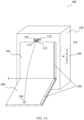
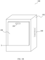
- FIGS. 1A-1C are schematic diagrams of a dishwasher 100 having a door lock device 110 of the present disclosure, with a door of the dishwasher being in an open position, a closed position or one or more intermediate positions, such as a heat dissipation position.
- the dishwasher 100 has a dishwasher body 102, a cavity 104 for accommodating dishes, and a dishwasher door 106 for closing the cavity 104.
- the dishwasher door 106 can pivot about a pivot axis X to open or close the dishwasher door 106. Therefore, the dishwasher door 106 has three critical positions during a movement process: an open position, a closed position and a heat dissipation position, which correspond to the three positions shown in FIGS. 1A-1C , respectively, where the heat dissipation position is located between the open position and the closed position.
- the dishwasher door 106 may further have any position between any two of the above-mentioned three positions during the movement process, for example, any position between the heat dissipation position and the closed position, or any position between the heat dissipation position and the open position.
- the door lock device 110 is mounted inside the dishwasher body 102, the door lock device 110 has a door lock slider 112, and a door hook hole 114 is formed in an end of the door lock slider 112.
- the door lock slider 112 can be extended from a door lock device extension hole 107 formed in the dishwasher body 102, and engaged with the door hook 108 (see FIG. 2A ) by means of the door hook hole 114. Therefore, the door lock slider 112 has two critical positions of movement, that is, an extended position and a retracted position.
- a door latch is provided inside the dishwasher door 106 and includes the above-mentioned door hook 108, and a door latch handle 105 for pulling the door latch is provided on an outer side of the dishwasher door 106 and configured to disengage the door hook 108 of the door latch from the door hook hole 114, such that the dishwasher door 106 can be pulled open.
- a door latch hole 109 is formed in an inner side of the dishwasher door 106 at a position corresponding to the door latch, such that the door lock slider 112 can pass through the door latch hole 109 to be inserted into the door latch and thus be engaged with the door hook 108 inside the dishwasher door 106.
- the door hook 108 may be re-engaged with the door hook hole 114 of the door lock slider 112 to allow the dishwasher door 106 to be closed or to allow the dishwasher door 106 to move under the drive of the door lock slider 112.
- the dishwasher 100 is further provided with a control device 160 and an obstacle detection component.
- the control device 160 is configured to control and actuate the movement of the door lock slider 112 and to receive an obstacle signal
- the obstacle detection component is configured to detect whether there is an obstacle in a door gap 111 (see FIG. 1C ) (e.g., a user accidentally reaching his/her hand into the gap) during the closing process of the dishwasher door 106.
- the obstacle detection component may be a current detection component 445/446 (see FIG. 4C ), that is, the current detection component 445/446 detects a current change of a driving motor 226 (see FIGS. 2A-2C and FIGS. 4A-4C ) to determine whether there is an obstacle in the door gap 111.
- the obstacle detection component may also be an obstacle sensor 150, such as a photoelectric (photosensitive) sensor, an infrared sensor or a capacitive sensor (see FIG. 1A ), which is disposed between the dishwasher door 106 and the dishwasher body 102. It is determined whether there is an obstacle in the door gap 111 based on the obstacle signal detected by the obstacle sensor 150, and a signal indicating whether there is an obstacle is transmitted to the control device 160 by means of a connecting line 152.
- an obstacle sensor 150 such as a photoelectric (photosensitive) sensor, an infrared sensor or a capacitive sensor (see FIG. 1A )
- control device 160 controls the dishwasher door 106 to stop closing or move reversely, so as to avoid further clamping of the obstacle.
- FIG. 1A is a schematic diagram of the dishwasher door 106 of the present disclosure in the open position.
- the door lock slider 112 when the dishwasher door 106 is in the open position, the door lock slider 112 is disengaged from the door hook 108. Normally, when the dishwasher door 106 is in the open position, the door lock slider 112 does not extend from the door lock device extension hole 107. Even if the door lock slider 112 is in the extended position, the control device 160 of the dishwasher 100 can also control the door lock slider to be retracted into the door lock device extension hole 107 (a specific control flow will be described in detail later).
- FIG. 1B is a schematic diagram of the dishwasher door 106 of the present disclosure in the closed position.
- FIG. 1C is a schematic diagram of the dishwasher door 106 of the present disclosure in the heat dissipation position.
- the dishwasher door 106 When the dishwasher door 106 is in the heat dissipation position, if it is required to open the dishwasher door 106 further, the user needs to pull the door latch handle 105 by means of manual intervention to disengage the door lock slider 112 from the door hook 108, so as to pull the dishwasher door 106 open.
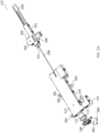
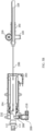
- a door hook hole 114 is formed in one end (e.g., the left end shown in the figure) of the door lock slider 112 and configured to receive the door hook 108 mounted in the door latch and can be engaged with the door hook 108, and a slider rope receiving hole 242 (see FIGS. 2B ) is formed in the other end (e.g., the right end shown in the figure) of the door lock slider 112 and configured to connect the rope 206.
- Four door lock box fixing members 291, 292, 293, 294 are provided on the door lock box housing 216 of the door lock box 204 and configured to fixedly mount the door lock box 204 inside the dishwasher body 102.
- a door switch 260 is disposed at an inner side of the dishwasher door 106, and the door switch 260 has a door switch contact 262.
- a rotating cam (not shown) of the door hook 108 is in a position where the rotating cam is in contact with the door switch contact 262, so as to switch off the door switch 260; and when the door hook hole 114 in the door lock slider 112 is disengaged from the door hook 108, the rotating cam of the door hook 108 swings to a position where the rotating cam is not in contact with the door switch contact 262, so as to switch on the door switch 260.
- ON and OFF of the door switch 260 may also be set to be contrary to those in the above embodiment, as long as it can be ensured that the ON and OFF of the door switch 260 can distinguish and indicate the engagement or disengagement between the door hook hole 114 and the door hook 108.
- the driving assembly 202 includes a driving device upper cover 222 and a driving device housing 224, a driving rack 228 is disposed inside the driving assembly, and the driving rack 228 can reciprocate linearly relative to the driving assembly 202.
- a rack pulling rope receiving hole 244 is formed in an end (e.g., the left end shown in the figure) of the driving rack 228 and configured to connect the rope 206.
- the driving assembly 202 further includes a driving motor 226, which is preferably a servo motor, configured to drive the driving rack 228 to reciprocate.
- the door lock slider 112 and the driving rack 228 can be connected together by means of the rope 206, and a rightward movement of the driving rack 228 relative to the driving assembly 202 can cause a rightward movement of the door lock slider 112 relative to the door lock box 204; and a pull force on the door lock slider 112 can be released by means of a leftward movement of the driving rack 228 relative to the driving assembly 202, so as to allow the door lock slider 112 to move leftward, and the leftward movement of the door lock slider 112 is caused by an elastic potential energy stored in a biasing device (e.g., a coil spring) 232 (see FIGS. 3A-3C ).
- a biasing device e.g., a coil spring
- the door lock slider 112 is disposed inside the door lock box 204. As viewed from the top, the door lock slider 112 is disposed at an upper portion of the door lock box 216, and the biasing device, preferably the coil spring 232, which is cooperatively connected to the door lock slider 112, is disposed below the door lock slider 112.
- the coil spring 232 can generate a leftward biasing force on the door lock slider 112 by means of its own torsion, to allow the door lock slider 112 to have a tendency to move from a retracted position to an extended position.
- a locking pin assembly 218 arranged perpendicular to the door lock slider 112 is disposed below the left side of the door lock box 204 and configured to lock the door lock slider 112 in the retracted position shown in FIG. 2A .
- a positioning switch 264 for detecting a position of the door lock slider 112 is disposed inside the door lock box 204 and configured to indicate whether the door lock slider 112 is in the retracted position.
- a driving gear 220 is disposed inside the driving assembly 202 and can maintain in tooth engagement with the driving rack 228.
- the driving motor 226 can actuate the driving gear 220 to rotate and cause the driving rack 228 to reciprocate linearly by means of the engagement transmission between the driving gear 220 and the driving rack 228.
- the door lock slider 112 and the driving rack 228 can be rigidly connected and arranged to move in the same movement direction, for which reference may be made to the description of FIG. 2C below.
- FIG. 2C is a perspective view of another embodiment of the door lock device of the present disclosure, and the door lock box upper cover 214 of the door lock box 204 is hidden in FIG. 2C , so that a connecting relationship between the door lock slider 112 and the driving rack 228 can be more clearly seen.
- the differences between the door lock device 210 and the door lock device 110 shown in FIGS. 2A and 2B are that the door lock slider 112 and the driving rack 228 of the door lock device 210 are directly rigidly connected together instead of by means of flexible connection by the rope 206, and the biasing device 232 of the door lock device 110 in FIGS. 2A and 2B is not provided in the door lock device 210.
- Other identical parts will not be repeated. Since the door lock slider 112 and the driving rack 228 of the door lock device 210 are rigidly connected, the driving rack 228 can be actuated to reciprocate by the driving motor 226, so as to cause the door lock slider 112 to reciprocate between the extended position and the retracted position.
- FIGS. 2D and 2E are top views showing the door lock slider 112 in the door lock box 204 in the retracted position and the extended position, respectively.
- the door lock box upper cover 214 of the door lock box 204 is hidden to show a cooperation relationship of various components inside the door lock box 204 and to show a movement distance of the door lock slider 112 between the retracted position and the extended position, so as to reflect a gap distance by which the dishwasher door 106 can be opened.
- the positioning switch 264 has a positioning switch contact 266, a downward protruding switch actuating portion 212 is disposed at a right end of the door lock slider 112 at a position corresponding to the positioning switch 264.
- the door lock slider 112 can linearly reciprocate in the door lock box 204. Therefore, the switch actuating portion 212 of the door lock slider 112 also reciprocate with the movement of the door lock slider 112.
- the switch actuating portion 212 of the door lock slider 112 is in contact with the positioning switch contact 266 of the positioning switch 264 to switch off the positioning switch 264.
- the positioning switch 264 can send a signal indicative of the door lock slider 112 being in the retracted position to the control device 160 (see FIGS. 7A-7D ) of the electrical apparatus, so as to execute a control program for a next operation.
- the control device 160 see FIGS. 7A-7D
- the switch actuating portion 212 of the door lock slider 112 is out of contact with the positioning switch contact 266 of the positioning switch 264 to switch on the positioning switch 264, and in this case, the positioning switch 264 can send a signal indicative of the door lock slider 112 moving away from the retracted position to the control device 160 of the electrical apparatus, so as to execute the control program for a next operation.
- the positioning switch 264 may not be provided in the door lock box 204.
- the movement of the door lock slider 112 may be limited by providing a corresponding mechanical limiting structure in the door lock box 204, and the movement distance of the door lock slider 112 may be controlled or the position of the door lock slider 112 may be detected by controlling a rotational speed and a rotational duration of the servo motor.
- the locking pin assembly 218 inside the door lock box 204 includes a locking pin 208, a locking pin spring 207 and a linear motor which is preferably a locking pin coil 209.
- the locking pin coil 209 has a movable actuating rod 211 for actuating the movement of the pin 208.
- the locking pin spring 207 is disposed between the locking pin 208 and the actuating rod 211 of the locking pin coil 209 and can provide an elastic force (a resetting force) for moving the locking pin 208 away from the locking pin coil 209.
- the locking pin coil 209 can receive a pulse signal from the control device 160 (see FIGS.
- a locking pin slot 215 is formed in a lower portion of the door lock slider 112 at a position corresponding to the locking pin 208, and is configured to receive the inserted locking pin 208.
- the locking pin 208 is automatically inserted (sprung) into the locking pin slot 215 in the lower portion of the door lock slider 112 under the action of the locking pin spring 207 to lock the door lock slider 112.
- the electromagnetic force can be generated to overcome the elastic force of the locking pin spring 207, so as to pull back the locking pin 208 to a non-locked position as shown in FIG. 2E .
- the door lock slider 112 moves to a position other than the retracted position, since the locking pin 208 cannot be aligned with the locking pin slot 215, the locking pin 208 cannot be inserted into the locking pin slot 215 and thus remains in a withdrawn (unlocked) position.
- the door lock slider 112 is in a free state and can very easily slide.
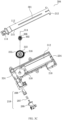
- FIGS. 3A-3C are structural schematic diagrams of the door lock box 204.
- FIG. 3A is a perspective view of the door lock box 204, in which the door lock box upper cover 214 of the door lock box 204 is hidden to show more components inside the door lock box 204.
- FIG. 3B is a partial enlarged perspective view of a circled part A of the door lock slider 112 shown in FIG. 3A , where part of a material of an outer side of the door lock slider 112 is hidden in FIG. 3B to more clearly show a slider recess 308 and a slider rack 304 of the door lock slider 112, and a cooperation relationship between the door lock slider 112 and the coil spring 232.
- FIG. 3C is an exploded mounting view of the door lock box 204 shown in FIG. 3A to show a mounting relationship between various components inside the door lock box 204.
- the door lock slider 112 has a slider body 301 and the slider recess 308 (see FIG. 3B ) formed in an inner side of the slider body 301 in a length direction of the slider body 301.
- the slider rack 304 is disposed at one side of the slider recess 308 and has slider rack teeth 305.
- slider racks may also be provided on each of opposite sides of the slider recess 308.
- a slider gear 302 is provided inside the door lock box 204 and is mounted in the slider recess 308.
- Slider gear teeth 306 are provided on an upper portion of the slider gear 302, and a lower portion of the slider gear 302 is fixed in the center of the coil spring 232.
- the slider gear 302 and the coil spring 232 have the same coil spring rotation axis 314. Therefore, when the slider gear 302 rotates clockwise, the slider gear 302 causes the coil spring 232 to start gradual outward elastic torsion from the center of the coil spring, such that elastic potential energy can be stored in the coil spring 232.
- the slider gear 302 can be engaged with the slider rack teeth 305 of the slider rack 304 by means of the slider gear teeth 306 to form a gear-rack transmission structure. Therefore, the rotation of the slider gear 302 around the coil spring rotation axis 314 can cause the slider rack 304 to move linearly, and the linear movement of the slider rack 304 can cause the slider gear 302 to rotate around the coil spring rotation axis 314.
- the coil spring 232 is formed by coiling a continuous sheet metal material.
- a slider gear fixing portion 322 (see FIG. 3C for details) is disposed at a start end of a coil (i.e., the center of the coil spring 232), and is configured to be fixedly connected at a lower end of the slider gear 302, and a outer tail end 316 of the coil spring 232 is fixed to the coil spring fixing portion 318 on the door lock box housing 216.
- the slider gear 302 rotates, the slider gear 302 causes a start end of the coil spring 232 to start to coil by means of the connection between the lower end of the slider gear 302 and the slider gear fixing portion 322. Since the tail end 316 of the coil spring 232 is fixed at the coil spring fixing portion 318 of the door lock box housing 216, the entire coil spring 232 does not rotate, but only torsional deformation occurs inside the coil spring 232 to store the elastic potential energy.
- the coil spring 232 is disposed in a coil spring mounting recess 324 of the door lock box housing 216, such that the coil spring 232 can be twisted in a space defined by the coil spring mounting recess 324.
- the door lock slider 112 is disposed in a sliding groove 312 of the door lock box housing 216, such that the door lock slider 112 can be accommodated in the sliding groove 312 and linearly move leftward or rightward in a length direction of the sliding groove.
- the door lock slider 112, the slider gear 302, the coil spring 232 and the door lock box housing 216 are sequentially placed in a vertical direction, and FIG. 3C shows a mounting relationship between these four components in the vertical direction.
- the locking pin coil 209, the locking pin spring 207 and the locking pin 208 are sequentially placed in a front-rear direction, and FIG. 3C shows a mounting relationship between these three components in the front-rear direction.
- an acting area at which the slider gear 302 drives the door lock slider 112 coincides or substantially coincides with a movement path of the door lock slider 112, and a rotation axis (i.e., the coil spring rotation axis 314) of the slider gear 302 is at a middle line in the length direction of the door lock slider 112.
- the acting area where the slider gear teeth 306 of the slider gear 302 are engaged with the slider rack teeth 305 of the door lock slider 112 is located inside the slider body 301 of the door lock slider 112.
- FIGS. 4A-4C illustrate a structure and a schematic control chart of the driving assembly 202.
- FIG. 4A is an enlarged view of the driving assembly 202, with the driving device upper cover 222 of the driving assembly 202 hidden to show more components inside the driving assembly 202.
- FIG. 4B is an exploded mounting view of the driving assembly 202 shown in FIG. 4A to show a mounting relationship between various components inside the driving assembly 202.
- FIG. 4C is a block diagram of connection and control of the driving motor 226.
- the driving assembly 202 includes the driving gear 220, the driving rack 228, a gear transmission component 406, and the driving motor 226.
- the driving gear 220, the driving rack 228 and the gear transmission component 406 are disposed inside the driving device housing 224 of the driving assembly 202, and the driving motor 226 is partially disposed outside the driving device housing 224.
- the driving gear 220 or the driving rack 228, the gear transmission component 406, the driving motor 226 and the driving device housing 224 are vertically placed, and FIG. 4B shows the vertical assembly relationship between these components.
- the driving device housing 224 has a driving gear accommodating cavity 422 for accommodating the driving gear 220 such that the driving gear 220 is limited to rotate inside the driving gear accommodating cavity 422.
- the driving device housing 224 further has a driving rack sliding groove 424, such that the driving rack 228 can be accommodated in the driving rack sliding groove 424 and linearly reciprocate in a length direction of the driving rack sliding groove.
- the driving motor 226 has a driving motor output shaft 408, and the driving motor output shaft 408 is cooperatively connected to the driving gear 220 by means of the gear transmission component 406, so as to drive the driving gear 220 to rotate.
- the driving gear 220 has driving gear outer teeth 416, and driving rack teeth 412 are provided on an upper side of the driving rack 228 and can be engaged with the driving gear outer teeth 416 of the driving gear 220, such that forward and reverse rotations of the driving motor 226 can cause the driving rack 228 to reciprocate in the driving rack sliding groove 424.
- the driving motor 226 further has positive and negative plugs 434, 436, and the positive and negative plugs 434, 436 can be electrically connected to a drive circuit 442 and an external power supply (see FIG. 4C ) to provide power for the rotation of the driving motor 226 and to control a direction of rotation of the driving motor 226.
- the drive circuit 442 may be an motor driving module or a relay.
- the current detection component 445/446 is connected to the drive circuit 442 and the control device 160, and in an embodiment of the present disclosure, only one current detection component 445/446 may be provided. For example, only the current detection component 446 is provided and the current detection component 446 is connected to the control device 160 by means of a connecting line 462.
- the current detection component 445/446 includes a current detection module and component(s) for performing amplification and other processing operations on the circuit.
- the current detection component 445/446 may also include only a current detection module.
- the current detection module of the current detection component 445/446 is connected to a positive or negative pole of the power supply.
- the control device 160 may generate a motor control signal based on an analog signal received by the current detection component 446, to control the drive circuit 442 by means of a control line 456, so as to control the rotation or stop and the forward or reverse rotation of the driving motor 226.
- An upper limit threshold of a current may be set in advance in a control program, and this upper limit threshold is greater than a current during a normal operation. Once the current of the motor exceeds this upper limit threshold, the control device 160 can identify by means of the current detection component 445/446 that there is an obstacle in the door gap 111 of the dishwasher 100, and thus control to stop the rotation or reverse the rotation of the motor to stop closing the door so as to allow to remove the obstacle.
- a movement operation process of the door lock slider 112 and the driving rack 228 will be described below with reference to FIGS. 3A-4B .
- the control device 160 sends a pulse signal to the locking pin coil 209 to generate an electromagnetic actuating force on the locking pin 208, such that the locking pin 208 is withdrawn from the locking pin slot 215 of the door lock slider 112 by overcoming the elastic force of the locking pin spring 207, so as to unlock the door lock slider 112.
- the driving motor 128 rotates forward to drive the driving rack 228 to linearly move leftward by means of the driving gear 220.
- the coil spring 232 can release the elastic potential energy stored therein to cause the slider gear 302 to rotate counterclockwise, and the counterclockwise rotation of the slider gear 302 causes the door lock slider 112 to linearly move leftward in the sliding groove 312 by means of the slider rack 304 meshing with the slider gear.
- the driving motor 128 rotates reversely to cause the driving rack 228 to linearly move rightward by means of the driving gear 220.
- the rope 206 can be pulled by means of the rightward linear movement of the driving rack 228, and thus the door lock slider 112 is pulled to linearly move rightward in the sliding groove 312.
- the rightward linear movement of the door lock slider 112 causes, by means of the slider rack 304, the clockwise rotation of the slider gear 302 meshing with the slider rack, and the clockwise rotation of the slider gear 302 can cause the torsion of the coil spring 232 and the storage of the elastic potential energy in the coil spring.
- the locking pin slot 215 is aligned with the locking pin 208 in position, such that the locking pin 208 can be inserted (sprung) into the locking pin slot 215 under the action of the locking pin spring 207, so as to lock the door lock slider 112 in the retracted position.
- FIGS. 5A-5C show schematic diagrams of the door lock slider 112 moving between the extended position and the retracted position.
- FIG. 5A is a schematic diagram of the door lock slider 112 in the extended position
- FIG. 5B is a schematic diagram of the door lock slider 112 in the retracted position
- FIG. 5C is a schematic diagram of the door lock slider 112 that is forced back from the extended position to the retracted position.
- the dishwasher door 106 when the dishwasher 100 performs a heat dissipation operation, the dishwasher door 106 is in the heat dissipation position (corresponding to a state as shown in FIG. 1C ), the door lock slider 112 is in the extended position at this moment, and the door hook 108 remains engaged with the door hook hole 114 of the door lock slider 112 (not shown).
- the control device 160 controls to pull the door lock slider 112 to move from the extended position as shown in FIG. 5A to the retracted position as shown in FIG.
- the door lock slider 112 Since the door lock slider 112 is flexibly connected to the driving rack 228 by means of the rope 206, after the door lock slider 112 is forced back to the retracted position under the action of the push force on the door, the driving rack 228 still remains in a position corresponding to the extended position of the door lock slider 112 without reset, as shown in FIG. 5C , and in this case, after the positioning switch 264 detects that the door lock slider 112 is in the retracted position, the control device 160 controls the driving rack 228 to be reset in the state shown in FIG. 5B . If the user pulls the door latch handle 105 to open the dishwasher door 106 in the heat dissipation position of the dishwasher door 106 shown in FIG.
- the control device 160 cannot control the door to be closed.
- the door lock slider 112 is forced back to the retracted position shown in FIG. 5C under the action of the push force, and the locking pin 208 can be inserted (sprung) into the locking pin slot 215 under the action of the locking pin spring, so as to lock the door lock slider 112 in the retracted position.
- the door lock slider 112 Since the door lock slider 112 is flexibly connected to the driving rack 228 by means of the rope 206, the door lock slider 112 does not push the driving rack 228 to move during movement to the retracted position, that is, a rightward push force on the door lock slider 112 is not transmitted to the driving assembly 202 (the push force on the door lock slider 112 is isolated by the rope 206), and thus the rack 228, the gear 220 and the motor 226 of the driving assembly 202 remain unchanged in position and state to serve a function of protecting the driving assembly 202.
- a control process for the door lock device 110 will be described in detail below.
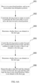
- FIGS. 6A-6C show control flow charts of operations of the dishwasher 100.
- FIG. 6A is a control logic diagram of closing the dishwasher door;
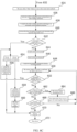
- FIG. 6B shows a flow chart of a resetting process of the dishwasher door 106, that is, the dishwasher door 106 is moved to or remains in a closed state regardless of the state thereof;
- FIG. 6C shows a flow chart of activating a dish washing program and a heat dissipation program after the resetting of the dishwasher door 106 is completed.
- steps S01 and S02 when the dishwasher door 106 is in the opened position or the intermediate position (the heat dissipation position) and needs to be closed, the control device 160 controls the driving motor 226 to rotate reversely (corresponding to a direction for closing the door), causing the door lock slider 112 to move from the extended position to the retracted position, so as to pull back the dishwasher door 106 to the closed position.
- steps S03 and S04 it is determined whether there is an obstacle in the door gap during pulling back the dishwasher door 106 to the closed position, and if there is an obstacle, the control device 160 controls the driving motor 226 to rotate forward (corresponding to a direction for opening the door) for a predetermined period of time to ensure that the obstacle is removed from the door gap, and then controls the driving motor 226 to rotate reversely.
- steps S05 and S06 it is again determined whether there is an obstacle in the door gap, and if there is an obstacle, the step S04 is repeated until the obstacle is removed from the door gap, and the door is then pulled back to the closed position.
- FIGS. 6B and 6C show details of a specific control flow.
- step 602 it executes a reset operation program for the dishwasher door, and the control device 160 detects pulsed states of the door switch 260 and the positioning switch 264 in the following reset operation.
- the door switch 260 and the positioning switch 264 each have two pulsed states, namely, a low-level state and a high-level state.
- the low-level state of each of the door switch 260 and the positioning switch 264 indicates that the switch is in a switched-on state
- the high-level state indicates that the switch is in a switched-off state.
- step 602 the flow proceeds to step 604.
- step 604 it is determined whether the door switch 260 is in the switched-off state. If the door switch 260 is in the switched-off state, that is, the door hook hole in the door lock slider 112 is engaged with the door hook of the door, the flow proceeds to step 606; and if the door switch 260 is not in the switched-off state, that is, the door hook hole 114 in the door lock slider 112 is disengaged from the door hook 108, the flow proceeds to step 608.
- step 606 it is determined whether the positioning switch 264 is in the switched-off state. If the positioning switch 264 is in the switched-off state, that is, the door lock slider 112 is in the retracted position, the flow proceeds to step 612; and if the positioning switch 264 is not in the switched-off state, that is, the door lock slider 112 is not in the retracted position, the flow proceeds to step 610.
- step 608 it is determined whether the positioning switch 264 is in the switched-off state. If the positioning switch 264 is in the switched-off state, that is, the door lock slider 112 is in the retracted position, the flow proceeds to step 620; and if the positioning switch 264 is not in the switched-off state, that is, the door lock slider 112 is not in the retracted position, the flow proceeds to step 622.
- step 610 since the door hook hole 114 of the door lock slider 112 is engaged with the door hook 108 and the door lock slider 112 is not in the retracted position, that is, the dishwasher door 106 is pushed open with a gap by the door lock slider 112, the control device 160 activates an automatic door closing program, and the driving motor 226 rotates reversely to pull back the dishwasher door 106 to the closed position.
- step 632 the flow proceeds to step 632.
- step 612 since the door hook hole 114 of the door lock slider 112 is engaged with the door hook 108 and the door lock slider 112 is in the retracted position, that is, the door is in the closed position, the control program does not perform any operation, and the door lock device does not perform any actions. After the operation of step 612 is completed, the flow proceeds to step 632.
- step 620 since the door hook hole 114 of the door lock slider 112 is disengaged from the door hook 108 and the door lock slider 112 is in the retracted position, that is, the door is in the open position (manually opened) and the door lock slider 112 is retracted, the control program does not perform any operation and only sends a prompt signal indicative of the dishwasher door 106 being opened to the user.
- step 630 the flow proceeds to step 630.
- step 622 since the door hook hole 114 of the door lock slider 112 is disengaged from the door hook 108 and the door lock slider 112 is in the extended position, that is, the dishwasher door 106 is in the open position (manually opened) and the door lock slider 112 is not retracted, the control device 160 activates the automatic door closing program, and the driving motor 226 rotates reversely to pull back the door lock slider 112 to the retracted position.
- step 622 the flow proceeds to step 630.
- step 630 since the dishwasher door is still in the open position (manually opened) and the door hook 108 is disengaged from the door lock slider 112, the door cannot be closed by means of the driving motor 226 driving the door lock slider 112, and the user needs to manually close the door.
- step 632 the flow proceeds to step 632.
- step 632 the control device 160 completes the reset operation program, the dishwasher door 106 has been closed, and the flow proceeds to step 634.
- a dish washing program and a heat dissipation program can be activated for the dishwasher after the reset operation program is completed.
- the user can activate the dish washing program by clicking a "Start" button on a user interaction panel of the dishwasher, or by means of another smart start method (e.g., the control program).
- the flow proceeds to step 636.
- step 636 the dish washing program is activated, and a dish washing operation begins. After the operation of step 636 is completed, the flow proceeds to step 638.
- step 638 after the dish washing operation is completed, an automatic heat dissipation program is triggered. After the operation of step 638 is completed, the flow proceeds to step 640.
- step 640 the heat dissipation program begins, the control device 160 controls the door lock slider 112 to move from the retracted position to the extended position, and the dishwasher door 106 is automatically opened. After the operation of step 640 is completed, the flow proceeds to step 642.
- step 642 it is determined whether there is a manual intervention from the user during automatic opening of the dishwasher door 106. If there is a manual intervention from the user, the flow proceeds to step 654; and if there is no manual intervention from the user, the flow proceeds to step 644.
- step 654 it is determined whether the manual intervention from the user is manual door opening or manual door closing. If the user manually open the door, that is, the door hook hole 114 in the door lock slider 112 is disengaged from the door hook 108, the door switch 260 changes from the switched-off state to the switched-on state, and the flow proceeds to step 658; and if the user manually closes the door, the door lock slider 112 is pushed to the retracted position, the positioning switch 264 changes from the switched-on state to the switched-off state, and the flow proceeds to step 656.
- step 656 since the dishwasher door 106 is manually closed by the user, it may indicate that the user does not wish to perform the heat dissipation operation.
- the door lock slider 112 is pushed to the retracted position by a push force of the user manually pushing the door, and the push force acting on the door lock slider 112 is blocked by the flexible rope 206, so that the driving rack 228 remains unchanged in position (refer to the state as shown in FIG. 5C ), and thus the control device 160 needs to activate the automatic door closing program such that the driving motor 226 rotates reversely to pull back the driving rack 228.
- step 670 After the operation of step 656 is completed, the flow proceeds to step 670.
- step 658 since the dishwasher door 106 is already manually pulled open and the door lock slider 112 is still in the extended position or in a position between the retracted position and the extended position, the control device 160 activates the automatic door closing program such that the driving motor 226 rotates reversely to pull back the door lock slider 112.
- step 658 the flow proceeds to step 660.
- step 660 since the dishwasher door 106 is still in an open state, the user needs to manually close the dishwasher door 106 after the heat dissipation program ends. After the operation of step 660 is completed, the flow proceeds to step 670.
- step 644 if there is no manual intervention from the user, the control device 160 controls the door lock slider 112 to move from the retracted position to the extended position, and the dishwasher door 106 is automatically opened to the heat dissipation position. After the operation of step 644 is completed, the flow proceeds to step 646.
- step 646 after the dishwasher door 106 is automatically opened to the heat dissipation position, the heat dissipation program is activated, and the dishwasher begins to dissipate heat. After the operation of step 646 is completed, the flow proceeds to step 648.
- step 648 after the heat dissipation program ends, the automatic door closing program of the dishwasher is triggered. After the operation of step 648 is completed, the flow proceeds to step 650.
- step 650 the control device 160 controls the driving motor 226 to rotate reversely (corresponding to the direction for closing the door), causing the door lock slider 112 to move from the extended position to the retracted position, so as to pull back the dishwasher door 106 from the heat dissipation position to the closed position.
- step 652 it is determined whether there is a manual intervention from the user during automatically pulling back the dishwasher door 106. If there is a manual intervention from the user, the flow proceeds to step 654, and the above-mentioned steps are repeated; and if there is no manual intervention from the user, the flow proceeds to step 662.
- step 662 it is determined whether an obstacle is detected in the door gap 111 of the dishwasher 100 during automatically pulling back the dishwasher door 106. If no obstacle is detected, the flow proceeds to step 668; and if an obstacle is detected, the flow proceeds to step 664.
- step 664 since it is detected that there is an obstacle in the door gap 111 of the dishwasher 100, in order to ensure that the obstacle can be removed, the control device 160 controls the driving motor 226 to rotate forward (corresponding to the direction for opening the door) for 0.5 seconds or controls the driving motor 226 to stop rotating for 0.5 seconds. After the operation of step 664 is completed, the flow proceeds to step 666.
- step 666 the driving motor 226 rotates forward such that the dishwasher door 106 can leave a certain space for removing the obstacle.
- step 668 it is determined whether the positioning switch 264 is in the switched-off state. If the positioning switch 264 is in the switched-off state, that is, the door lock slider 112 is pulled back to the retracted position and the dishwasher door 106 is accordingly pulled back to the closed position by the door lock slider 112, the flow proceeds to step 670; and if the positioning switch 264 is not in the switched-off state, that is, the door lock slider 112 is not yet pulled back to the retracted position and the dishwasher door 106 is accordingly not yet pulled back to the closed position, the flow proceeds to step 650, and the above steps are repeated.
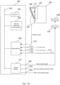
- FIGS. 7A-7D are block diagrams of two embodiments of the control device 160 of the present disclosure, which show specific components and connection relationships of the control device 160.
- the control device 160 can store and execute the programs of the dishwasher control flow as shown in FIGS. 6A-6C , and store and call various parameters required for the control flow.
- the difference between FIG. 7A and FIG. 7D is that different obstacle detection components are selected and arranged in the door lock device 110.
- the obstacle detection component in FIG. 7A is the current detection component 445, and it can be determined whether there is an obstacle in the door gap 111 by directly detecting a current change of the driving motor 226.
- FIG. 7B is a circuit diagram of a motor control part of the control device shown in FIG. 7A , and FIG.
- the obstacle detection component in FIG. 7D is the obstacle sensor 150, such as an infrared sensor, a photoelectric (photosensitive) sensor or a capacitive sensor, and it is determined whether there is an obstacle in the door gap 111 by detecting a change in an infrared signal, a photoelectric signal or a capacitive signal.
- the obstacle sensor 150 such as an infrared sensor, a photoelectric (photosensitive) sensor or a capacitive sensor
- the input interface 708 is configured to acquire and receive an obstacle signal fed back by the obstacle detection component (the current detection component 446 or the obstacle sensor 150), a user input signal, the pulse signal (high-level or low-level state) of the door switch 260 and the pulse signal (high-level or low-level state) of the positioning switch 264 by means of the connecting line 462 or 152, 714, 716, 718, and to convert these signal data into signals identifiable by the processor 704 and store the same in the memory 706.
- the obstacle detection component the current detection component 446 or the obstacle sensor 150
- a user input signal the pulse signal (high-level or low-level state) of the door switch 260 and the pulse signal (high-level or low-level state) of the positioning switch 264 by means of the connecting line 462 or 152, 714, 716, 718, and to convert these signal data into signals identifiable by the processor 704 and store the same in the memory 706.
- the processor 704 is configured to execute the programs stored in the memory 706 based on the acquired signals, generate a control signal for the driving motor 226 or a system prompt signal based on instruction(s) of the control programs, and send the generated signal(s) to the output interface 710.
- the output interface 710 is configured to receive a motor control signal from the processor 704 and transmit the motor control signal to the driving motor 226 by means of the control line 456 so as to control the forward rotation, reverse rotation or stop of the driving motor 226.
- the output interface 710 receives a door opening operation signal from the processor 704 and transmits the door opening operation signal to the locking pin coil 209 shown in FIGS.
- FIG. 7B and FIG. 7C are diagrams of specific control circuits of input and output parts of the control device 160 shown in FIG. 7A , respectively.
- the drive circuit 442 is a chip for driving the motor 226, and a chip model TB67H450 is used in an embodiment of the present disclosure.
- a chip model TB67H450 is used in an embodiment of the present disclosure.
- other chip models on the market may also be used, and the present disclosure is not limited to the chip model used in this embodiment.
- the drive circuit 442 has eight pins, wherein a pin 1 is a grounding pin (GND); a pin 2 is a first input pin (IN1) connected to a first output 731 of the output interface 710 and configured to receive a control signal; a pin 3 is a second input pin (IN2) connected to a second output 732 of the output interface 710 and configured to receive a control signal; a pin 4 is a motor output current setting pin configured to set a maximum output current (a protective current) of the motor; a pin 5 is a motor power supply pin configured to provide power (e.g., a power supply of +12 V) to the driving motor 226; a pin 6 is a first output pin (OUT1) connected to the positive /negative plug 434 of the motor and configured to control the rotation of the motor; a pin 7 is a motor output current detection pin configured to detect an output current of the motor (a motor sampling current); and a pin 8 is a second output pin (OUT2) connected to the positive/ negative
- the first output 731 and the second output 732 of the output interface 710 output digital signals indicating a low-level state or a high-level state.
- the first output 731 and the second output 732 can output four different combinations for the signals according to the permutation and combination principle, that is, the drive circuit 442 can receive four kinds of control signals, i.e., "low-low” signal, "high-low” signal, "low-high” signal and "high-high” signal, wherein the "low-low” signal is configured to control the motor to stop rotating, the "high-low” signal is configured to control the motor to rotate forward, the "low-high” signal is configured to control the motor to rotate reversely, and the "high-high” signal is configured to control the braking of the motor.
- the current detection component 446 is connected to the pin 7 of the drive circuit 442 and includes circuit connections and corresponding components as illustrated, wherein capacitors C 1 and C2 are configured for filtering, R3 represents a current sampling resistance, and four resistances R4, R5, R6, R7 collectively determine the amplification of an operational amplifier U7, and a voltage signal output from the operational amplifier U7 is transmitted to the input interface 708 by means of the connecting line 462.
- a voltage comparison threshold is stored in the control device 160. When the voltage signal input by the connecting line 462 is higher than the voltage comparison threshold, it is determined that there is an obstacle in the door gap, the control device 160 outputs the "high-low” signal to the drive circuit 442 to control the motor to rotate forward. When the voltage signal input by the connecting line 462 is not higher than the voltage comparison threshold, it is determined that there is no obstacle in the door gap, the control device 160 outputs the "low-high” signal to the drive circuit 442 to control the motor to rotate reversely.
- the connecting line 716 inputs a voltage of +5 V to the input interface 708, and when the door switch 260 is switched on, short circuiting occurs, and the connecting line 716 inputs a voltage of 0 V to the input interface 708.
- the connecting line 718 inputs a voltage of +5 V to the input interface 708, and when the positioning switch 264 is switched on, short circuiting occurs, and the connecting line 718 inputs a voltage of 0 V to the input interface 708.
- the output interface 710 outputs a digital signal by means of the connecting line 722, indicating the high-level state or the low-level state.
- the connecting line 722 outputs a high level
- a triode Q1 is powered on
- a relay switch 734 is switched on
- the locking pin coil 209 is powered on
- an electromagnetic force is generated to pull back the locking pin 208 to the non-locked position as shown in FIG. 2E .
- the triode Q1 When the connecting line 722 outputs a low level, the triode Q1 is not powered on, the relay switch 734 is switched off, the locking pin coil 209 is not powered on, and the locking pin 208 can be automatically inserted into the locking pin slot 215 of the door lock slider 112 under the action of the locking pin spring 207 so as to lock the door lock slider 112.
- the door lock device of the present disclosure can achieve at least the following beneficial technical effects.
- the driving motor can stop driving the door lock slider to move toward the retracted position or allow the door lock slider to move toward the extended position, thus stopping the door closing or re-opening the door, so as to prevent the obstacle from being clamped.
- the door lock assembly of the door lock device of the present disclosure can be connected to the driving device by means of the flexible rope, so that the relative positions of the door lock assembly and the driving device of the door lock device are freer to arrange.
- Rational relative position arrangement of the door lock assembly and the driving device can make full use of a narrow and small space of an electrical apparatus, that is, the position arrangement of the driving device is not limited by the position of the door lock assembly.
- the door lock assembly and the driving device can be mounted in two housings of the electrical apparatus, respectively.
- the door lock assembly of the door lock device of the disclosure can be connected to the driving device by means of the flexible rope, so that only the pull force can be transmitted and the push force can be isolated by means of the connection with the flexible rope. If a user forces the door to the closed position when the dishwasher door is not closed, the push force generated by the movement of the door lock slider toward the retracted position (the closed position) is not transmitted to the driving device, and thus the motor is not adversely affected.
- the control system has a set of corresponding response programs, so that the normal operation control of the (heat dissipation) program of the dishwasher is not affected, and thus the door lock slider is not separately exposed to the outside of the dishwasher, or the driving motor does not reset the driving rack to affect a next automatic door opening operation.
- the axis of rotation of the biasing device passes through the center of a movement path of the door lock slider, so that the biasing force of the biasing device on the door lock slider is more uniform, and the biasing force does not generate an excess torque on the door lock slider. Therefore, the position arrangement of the biasing device in the present disclosure is more rational, the door lock slider can be caused to move with a relatively small biasing force generated by the biasing device, so that the apparatus door can be driven to and for with a relatively small force, and requirements on the elastic force provided by the biasing device (such as the coil spring) are relatively low.
Landscapes
- Engineering & Computer Science (AREA)
- Textile Engineering (AREA)
- Power-Operated Mechanisms For Wings (AREA)
- Washing And Drying Of Tableware (AREA)
Abstract
The disclosure relates to a control method for a door lock device, the control method including: determining whether there is an obstacle in a gap with which a door of an electrical apparatus is opened in the process of the door moving toward a closed position; controlling a motor to rotate in a second direction of rotation for a predetermined period of time if there is an obstacle in the gap, and repeating the step until the obstacle is removed from the gap; and controlling the motor to rotate in a first direction of rotation if there is no obstacle in the gap, so as to allow the door to move to the closed position. The control method of the disclosure can prevent an obstacle (for example, a hand of a user accidentally reaching into the gap) from being clamped during an automatic door closing process for a dishwasher.
Description
- The present disclosure relates to a door lock device of an electrical apparatus, an electrical apparatus and a control method, and in particular to a door lock device capable of automatically opening and closing a door of an electrical apparatus, an electrical apparatus provided with the door lock device, and a control method for controlling automatic opening and closing of the door.
- A door of an electrical apparatus, such as a dishwasher, is generally provided with a door lock. A conventional door lock can be unlocked by means of physical pulling or locked by means of physical pushing, that is, the door can be unlocked by manually pulling a latch on the door, or the door can be locked by manually bumping a door hook of the door against a door hook hole.
- After a dishwasher completes a washing operation, it is typically required to further perform a drying operation, and a user expects that a door of the dishwasher can be kept in a partially open state in this case, for example, leaving a gap for allowing sufficient ventilation, such that hot steam is discharged from an internal cavity of the dishwasher, thus facilitating faster drying. During the drying operation, the user typically does not wait beside the dishwasher for the drying operation to be completed.
- Therefore, a door lock device may be arranged on one side of the dishwasher facing a door hook of the door, and the door lock device includes a door lock assembly, a driving device and a control device. The door lock device has a door lock slider, the door lock slider is provided with a door hook hole matching the door hook, and the control device controls the opening or closing of the door within an opening range by controlling the door lock slider to be extended by a distance or retracted, and thus achieving automatic opening of the door to a heat dissipation position or automatic closing of the door from the heat dissipation position.
- Specifically, if the door needs to be opened by a gap, for example, the door needs to be in the heat dissipation position, the door lock slider can remain in an extended position by means of the cooperative arrangement of a biasing device and the door lock slider in the door lock device. When the door gap is to be closed, a motor in the driving device is driven to overcome a biasing force of the biasing device and drive the door lock slider to move from the extended position to a retracted position, and in this case, biasing potential energy is stored in the biasing device; when the door gap needs to be opened again, the motor rotates reversely to gradually release a pull force on the biasing device, such that the biasing device can cause the door lock slider to move from the retracted position to the extended position under the action of the stored biasing potential energy, thus pushing the door to be opened by a distance.
- In the process of completing heat dissipation and closing the door of the dishwasher, the control device activates an automatic door closing program, and the driving motor pulls back the door lock slider from the extended position to the retracted position. If there is a foreign object or an obstacle in the door gap at this moment, for example, a user accidentally reaches his/her hand into the door gap, the obstacle may be clamped during the door closing process and thus the door cannot be closed normally.
- In addition, in the process of the dishwasher executing a heat dissipation program, if the user manually intervene to pull the door open, the door lock slider is disengaged from the door hook of the door, and thus the door lock slider extends out to be separately exposed to the outside of the dishwasher; and if the user manually intervenes to push the door to a closed position, although the door lock slider moves to the retracted position under the action of a push force on the door, since the door lock slider is connected to the driving component by means of a flexible rope, the rope blocks the push force on the door lock slider from the driving component, the motor and a driving rack of the driving component remain in a position corresponding to the extended position of the door lock slider without reset, and thus a subsequent automatic door opening operation is affected.
- Therefore, there is a need for a door lock device of a dishwasher and a control method therefor, in order to, regardless of the position of the door of the dishwasher, stop door closing or move the door in an opening direction as long as an obstacle is detected in a door closing process. Further, there is a need for a door lock device of a dishwasher and a control method therefor, such that in the process of executing a heat dissipation program of the dishwasher, even if a user manually intervenes a door opening or closing operation, there is a set of control programs for responding to the manual intervention from the user, which does not affect normal operations of the (heat dissipation) program of the dishwasher, and the door lock slider is not separately exposed to the outside of the dishwasher, or a driving motor resets a driving rack to not affect a next automatic door opening operation.
- Therefore, according to a first aspect of the present disclosure, a control method is provided for controlling a motor of a door lock device, the motor being configured to drive a door lock slider to move, and the door lock slider being configured to actuate a door of an electrical apparatus, wherein the control method includes: step S01, controlling the motor to rotate in a first direction of rotation to allow the door lock slider to be retracted so as to move the door toward a closed position if the door is in a non-closed position; step S02, determining whether there is an obstacle in a gap with which the door is opened in the process of the door moving toward the closed position; controlling the motor to rotate in a second direction of rotation opposite the first direction of rotation for a first predetermined period of time if there is an obstacle in the gap, and controlling the motor to rotate in the first direction of rotation after the first predetermined period of time ends; and repeating the aforementioned operations in step S02 until the obstacle is removed from the gap; and step S03, moving the door to the closed position.
- According to the first aspect of the present disclosure, in step S01, if there is a manual intervention, the following steps are performed: step S01-1, controlling the motor to rotate in the first direction of rotation to allow the door lock slider to be retracted if the manual intervention is manual door opening and the door lock slider is disengaged from the door; performing a manual door closing operation after the door is kept in an open position for a period of time, and proceeding to step S03 after the manual door closing operation is completed; or step S01-2, controlling the motor to rotate in the first direction of rotation if the manual intervention is manual door closing, and proceeding to step S03 after the manual door closing operation is completed.
- According to the first aspect of the present disclosure, in step S02, whether there is an obstacle in the gap is determined by means of measuring a current change of the motor.
- According to the first aspect of the present disclosure, in step S02, whether there is an obstacle in the gap is determined by means of measuring a change of an infrared signal, a photoelectric signal or a capacitive signal in the gap.
- According to the first aspect of the present disclosure, prior to step S01, the control method further has the following steps: step S011, closing the door, and performing a dish washing operation with the door in the closed position, and in this case, the door lock slider being in a retracted position and connected to the door; and step S012, controlling the motor to rotate in the second direction of rotation to allow the door lock slider to be extended out, so as to move the door toward a predetermined position; and step S013, opening the door with the gap and keeping the door for a second predetermined period of time in a state of being opened with the gap when the door is in the predetermined position, the door lock slider being in an extended position and keeping in connection with the door; and after the second predetermined period of time ends, proceeding to step S01.
- According to the first aspect of the present disclosure, the electrical apparatus performs a heat dissipation operation within the second predetermined period of time.
- According to the first aspect of the present disclosure, in step S02, the motor is controlled to continue to rotate in the first direction of rotation and it proceeds to step S03 if there is no obstacle in the gap or if the obstacle is removed from the gap.
- According to the first aspect of the present disclosure, in step S012, if there is a manual intervention, the following steps are performed: step S012-1, controlling the motor to rotate in the first direction of rotation to allow the door lock slider to be retracted if the manual intervention is manual door opening and the door lock slider is disconnected from the door; and performing a manual door closing operation after the door is kept in an open position for a period of time, and proceeding to step S03 after the manual door closing operation is completed; or step S012-2, controlling the motor to rotate in the first direction of rotation if the manual intervention is manual door closing, and proceeding to step S03 after the manual door closing operation is completed.
- According to a second aspect of the present disclosure, a door lock device is provided, the door lock device including a motor, a door lock slider, an obstacle detection component, and a control device, the control device being configured to control the rotation of the motor, the motor being configured to drive the door lock slider to move, and the door lock slider being configured to actuate a door of an electrical apparatus, wherein the door lock device is configured to open or close the door by means of the control method according to the first aspect of the disclosure.
- According to a third aspect of the present disclosure, a door lock device is provided for opening and closing a door of an electrical apparatus, wherein the door lock device includes: a door lock assembly, a driving assembly, an obstacle detection component, and a control device. The door lock assembly is configured to actuate the door, the door lock assembly including a door lock slider having an extended position and a retracted position. The driving assembly is connected with the door lock slider for allowing the door lock slider to reciprocate between the extended position and the retracted position. The obstacle detection component is configured to detect whether there is an obstacle in a gap with which the door is opened. The control device is configured to control the driving assembly based on a detection result from the obstacle detection component. The control device is configured to control the driving assembly to allow the door lock slider to move to the extended position so as to allow the door to move in a direction opposite a closed position when the door lock slider drives the door to move to the closed position and the obstacle detection component detects that there is an obstacle in the gap with which the door is opened.
- According to the third aspect of the present disclosure, the door lock device further includes: a driving motor configured to drive the driving assembly, wherein the control device is configured to control a rotation direction of the driving motor so as to control a movement of the driving assembly.
- According to the third aspect of the present disclosure, the obstacle detection component is a current detection component for detecting a current flowing through the driving motor.
- According to the third aspect of the present disclosure, the obstacle detection component is a photosensitive detection component, an infrared detection component or a capacitive detection component for detecting whether there is an obstacle in the gap with which the door is opened.
- According to the third aspect of the present disclosure, the door lock assembly further includes a positioning switch and a door switch. The control device is configured to control a rotation of the driving motor based on states of the positioning switch and the door switch. The positioning switch is switched off when the door lock slider is in the retracted position, and the positioning switch is switched on when the door lock slider is not in the retracted position, and the door switch is switched off when a door hook of the door is engaged with the door lock slider, and the door switch is switched on when the door hook of the door is disengaged from the door lock slider.
- According to the third aspect of the present disclosure, the door has an open position, the closed position and one or more intermediate positions between the open position and the closed position. When the door is in the closed position, the door lock slider is in the retracted position, the positioning switch is switched off, and the door switch is switched off. When the door is in the one or more intermediate positions, the door lock slider is in the extended position, the positioning switch is switched on, and the door switch is switched off. When the door is in the open position, the door lock slider is in the retracted position, the positioning switch is switched off, and the door switch is switched on.
- According to the third aspect of the present disclosure, the driving assembly includes: a driving gear and a driving rack, the driving gear being configured to be rotatable in a first direction of rotation or a second direction of rotation, the driving rack being engaged with the driving gear, the driving gear being configured to drive the driving rack to reciprocate in a first linear direction or a second linear direction, and the driving rack being connected to the door lock slider, so as to further cause the door lock slider to move.
- According to the third aspect of the present disclosure, the control device is configured to control the direction of rotation of the driving gear. The driving rack drives the door lock slider to move in the first linear direction such that the door lock slider is in the retracted position when the control device controls the driving gear to rotate in the first direction of rotation. The control device controls the driving gear to rotate in the second direction of rotation such that the door lock slider is capable of moving to the extended position in the second linear direction when the obstacle detection component detects that there is an obstacle in the gap with which the door is opened.
- According to the third aspect of the present disclosure, the door lock assembly further includes: a biasing device configured such that the door lock slider causes the biasing device to store a biasing force when the door lock slider moves in the first linear direction, and the biasing force stored in the biasing device is capable of driving the door lock slider to move from the retracted position to the extended position in the second linear direction when the driving gear rotates in the second direction of rotation.
- According to the third aspect of the present disclosure, when the door is controlled to move from the closed position to the one or more intermediate positions, the control device controls the driving gear to rotate in the second direction of rotation such that the door lock slider moves from the retracted position to the extended position; when the door is controlled to move from the one or more intermediate positions to the closed position, the control device controls the driving gear to rotate in the first direction of rotation such that the door lock slider moves from the extended position to the retracted position; when the door is manually moved from the closed position to the open position, the control device does not control the driving gear to rotate, and the door lock slider remains in the retracted position; and when the door is manually moved from the one or more intermediate positions to the open position, the control device controls the driving gear to rotate in the first direction of rotation such that the door lock slider moves from the extended position to the retracted position.
- According to the third aspect of the present disclosure, the door lock device further includes a flexible component, the door lock slider being connected to the driving assembly by means of the flexible component. When the driving gear rotates in the first direction of rotation, the driving rack pulls the door lock slider to move in the first linear direction by pulling the flexible component, so as to move the door lock slider to the retracted position. When the door lock slider is in the extended position and the door lock slider is pushed toward the retracted position, the flexible component can isolate a push force generated by the movement of the door lock slider, such that the driving assembly is not affected by the push force.
- According to a fourth aspect of the present disclosure, an electrical apparatus is provided, the electrical apparatus having a door, wherein the electrical apparatus is configured to open or close the door by means of a control method according to the first aspect of the disclosure.
- According to a fifth aspect of the present disclosure, an electrical apparatus is provided, the electrical apparatus having a door lock device according to the second and third aspects of the disclosure and a door.
- Some of the additional aspects and advantages of the present disclosure will be set forth in the following description, and some will be apparent from the following description, or be learned by practice of the present disclosure.
-
-
FIG. 1A is a schematic diagram of a dishwasher having a door lock device of the present disclosure, with a door of the dishwasher being in an open position; -
FIG. 1B is a schematic diagram of the dishwasher shown inFIG. 1A , with the door of the dishwasher being in a closed position; -
FIG. 1C is a schematic diagram of the dishwasher shown inFIG. 1A , with the door of the dishwasher being in a heat dissipation position; -
FIG. 2A is a perspective view of the door lock device of the present disclosure; -
FIG. 2B is an exploded mounting view of the door lock device shown inFIG. 2A ; -
FIG. 2C is a perspective view of another embodiment of the door lock device of the present disclosure; -
FIG. 2D is a top view of a door lock slider in a retracted position, with a door lock box upper cover hidden to show more components inside a door lock box; -
FIG. 2E is a top view of the door lock slider in an extended position, with the door lock box upper cover hidden to show more components inside the door lock box; -
FIG. 3A is a perspective view of the door lock box, with the door lock box upper cover of the door lock box hidden to show more components inside the door lock box; -
FIG. 3B is a partial enlarged perspective view of the door lock slider shown inFIG. 3A ; -
FIG. 3C is an exploded mounting view of the door lock box shown inFIG. 3A ; -
FIG. 4A is a perspective view of a driving assembly, with a driving device upper cover of the driving assembly hidden to show more components inside the driving assembly; -
FIG. 4B is an exploded mounting view of the driving assembly shown inFIG. 4A ; -
FIG. 4C is a block diagram of connection and control of a driving motor; -
FIG. 5A is a schematic diagram of the door lock slider in the extended position; -
FIG. 5B is a schematic diagram of the door lock slider in the retracted position; -
FIG. 5C is a schematic diagram of the door lock slider that is forced back from the extended position to the retracted position; -
FIG. 6A is a control logic diagram of closing the door of the dishwasher; -
FIG. 6B is a flow chart of a resetting process of the door of the dishwasher; -
FIG. 6C is a flow chart of activating a dish washing program and a heat dissipation program after resetting of the door of the dishwasher is completed; -
FIG. 7A is a block diagram of a control device, in which an obstacle detection component is a current detection component; -
FIG. 7B is a circuit diagram of a motor control part of the control device shown inFIG. 7A ; -
FIG. 7C is a circuit diagram of a switching signal and door opening operation signal control part of the control device shown inFIG. 7A ; and -
FIG. 7D is a block diagram of a control device, in which the obstacle detection component is an obstacle sensor. - Various specific embodiments of the present disclosure will be described below with reference to the accompanying drawings which form part of the present disclosure, but the embodiments do not limit the present disclosure. It should be understood that although the terms indicating orientations, such as "upper", "lower", "left", "right", "front", "rear", are used in the present disclosure to describe orientations of various illustrative structural parts and elements in the present disclosure, these terms used herein are merely for ease of description and are determined based on the illustrative orientation shown in the accompanying drawings. Since the embodiments disclosed in the present disclosure can be arranged in different orientations, these terms indicating directions are merely illustrative and should not be considered as limitations.
- The terms "first", "second", "third", etc. used in the present disclosure are merely used to distinguish different objects, instead of indicating that there is any particular sequential relationship between these objects. The term "comprise/include" and derivatives thereof mean inclusion without limitation. Unless otherwise specified and limited, the terms "mounting", "connecting" and "connection" should be understood broadly. For example, they may be a mechanical or electrical connection, internal communication between two elements, or a direct connection or indirect connection via an intermediate medium. For those of ordinary skills in the art, the specific meanings of the above terms can be understood according to specific cases. If possible, the same or similar reference numerals used in the present disclosure refer to the same elements.
-
FIGS. 1A-1C are schematic diagrams of adishwasher 100 having adoor lock device 110 of the present disclosure, with a door of the dishwasher being in an open position, a closed position or one or more intermediate positions, such as a heat dissipation position. - As shown in
FIGS. 1A-1C , thedishwasher 100 has adishwasher body 102, acavity 104 for accommodating dishes, and adishwasher door 106 for closing thecavity 104. Thedishwasher door 106 can pivot about a pivot axis X to open or close thedishwasher door 106. Therefore, thedishwasher door 106 has three critical positions during a movement process: an open position, a closed position and a heat dissipation position, which correspond to the three positions shown inFIGS. 1A-1C , respectively, where the heat dissipation position is located between the open position and the closed position. For those of ordinary skill in the art, thedishwasher door 106 may further have any position between any two of the above-mentioned three positions during the movement process, for example, any position between the heat dissipation position and the closed position, or any position between the heat dissipation position and the open position. - Still referring to
FIGS. 1A-1C , thedoor lock device 110 is mounted inside thedishwasher body 102, thedoor lock device 110 has adoor lock slider 112, and adoor hook hole 114 is formed in an end of thedoor lock slider 112. Thedoor lock slider 112 can be extended from a door lockdevice extension hole 107 formed in thedishwasher body 102, and engaged with the door hook 108 (seeFIG. 2A ) by means of thedoor hook hole 114. Therefore, thedoor lock slider 112 has two critical positions of movement, that is, an extended position and a retracted position. - A door latch is provided inside the
dishwasher door 106 and includes the above-mentioneddoor hook 108, and a door latch handle 105 for pulling the door latch is provided on an outer side of thedishwasher door 106 and configured to disengage thedoor hook 108 of the door latch from thedoor hook hole 114, such that thedishwasher door 106 can be pulled open. Adoor latch hole 109 is formed in an inner side of thedishwasher door 106 at a position corresponding to the door latch, such that thedoor lock slider 112 can pass through thedoor latch hole 109 to be inserted into the door latch and thus be engaged with thedoor hook 108 inside thedishwasher door 106. In a state that thedoor lock slider 112 is disengaged from thedoor hook 108, once thedishwasher door 106 or thedoor hook 108 bumps against thedoor lock slider 112, thedoor hook 108 may be re-engaged with thedoor hook hole 114 of thedoor lock slider 112 to allow thedishwasher door 106 to be closed or to allow thedishwasher door 106 to move under the drive of thedoor lock slider 112. - The
dishwasher 100 is further provided with acontrol device 160 and an obstacle detection component. Thecontrol device 160 is configured to control and actuate the movement of thedoor lock slider 112 and to receive an obstacle signal, and the obstacle detection component is configured to detect whether there is an obstacle in a door gap 111 (seeFIG. 1C ) (e.g., a user accidentally reaching his/her hand into the gap) during the closing process of thedishwasher door 106. The obstacle detection component may be acurrent detection component 445/446 (seeFIG. 4C ), that is, thecurrent detection component 445/446 detects a current change of a driving motor 226 (seeFIGS. 2A-2C andFIGS. 4A-4C ) to determine whether there is an obstacle in thedoor gap 111. The obstacle detection component may also be anobstacle sensor 150, such as a photoelectric (photosensitive) sensor, an infrared sensor or a capacitive sensor (seeFIG. 1A ), which is disposed between thedishwasher door 106 and thedishwasher body 102. It is determined whether there is an obstacle in thedoor gap 111 based on the obstacle signal detected by theobstacle sensor 150, and a signal indicating whether there is an obstacle is transmitted to thecontrol device 160 by means of a connectingline 152. - If it is detected that there is an obstacle in the
door gap 111 during the movement of thedishwasher door 106 from the heat dissipation position to the closed position under the control of thecontrol device 160, thecontrol device 160 controls thedishwasher door 106 to stop closing or move reversely, so as to avoid further clamping of the obstacle. -
FIG. 1A is a schematic diagram of thedishwasher door 106 of the present disclosure in the open position. - As shown in
FIG. 1A , when thedishwasher door 106 is in the open position, thedoor lock slider 112 is disengaged from thedoor hook 108. Normally, when thedishwasher door 106 is in the open position, thedoor lock slider 112 does not extend from the door lockdevice extension hole 107. Even if thedoor lock slider 112 is in the extended position, thecontrol device 160 of thedishwasher 100 can also control the door lock slider to be retracted into the door lock device extension hole 107 (a specific control flow will be described in detail later). -
FIG. 1B is a schematic diagram of thedishwasher door 106 of the present disclosure in the closed position. - As shown in
FIG. 1B , when thedishwasher door 106 is in the closed position, thedoor lock slider 112 is engaged with thedoor hook 108, and thedoor lock slider 112 is in the retracted position. In this case, thecontrol device 160 of thedishwasher 100 can control a distance by which thedoor lock slider 112 extends out, so as to open thedishwasher door 106 and adjust the size of the gap with which thedishwasher door 106 is opened. -
FIG. 1C is a schematic diagram of thedishwasher door 106 of the present disclosure in the heat dissipation position. - As shown in
FIG. 1C , when thedishwasher door 106 is in the heat dissipation position, thedoor lock slider 112 is engaged with thedoor hook 108, and thedoor lock slider 112 is in the extended position. For example, thedoor lock slider 112 shown inFIG. 1C extends out by a distance D (seeFIGS. 2D and 2E ) relative to the retracted position thereof. In this case, thedishwasher door 106 is opened with a maximum gap while the dishwasher door remains engaged with thedoor lock slider 112, that is, it can be approximately regarded as that thedoor gap 111 of the dishwasher inFIG. 1C has a width D. Thedoor gap 111 is used for subsequent drying and heat dissipation operation of thedishwasher 100 after a cleaning operation is completed. When thedishwasher door 106 is in the heat dissipation position, if it is required to open thedishwasher door 106 further, the user needs to pull the door latch handle 105 by means of manual intervention to disengage thedoor lock slider 112 from thedoor hook 108, so as to pull thedishwasher door 106 open. - The
dishwasher 100 shown inFIGS. 1A-1C is merely exemplary, and thedoor lock device 110 of the present disclosure can also be mounted on various types of electrical apparatuses having a cavity and a door for closing the cavity, such as a washing machine, a laundry dryer, a microwave oven, and can also be mounted on other non-electrical apparatuses. -
FIGS. 2A-2C are perspective views of two embodiments of the door lock device of the present disclosure. -
FIGS. 2A is a perspective view of thedoor lock device 110 of the present disclosure, which shows main components of thedoor lock device 110. - As shown in
FIGS. 2A , thedoor lock device 110 includes a door lock assembly (e.g., a door lock box 204), a drivingassembly 202 and a flexible component (e.g., a rope 206). Thedoor lock box 204 includes a door lock boxupper cover 214 and a doorlock box housing 216, an elongateddoor lock slider 112 is disposed inside the door lock box, and thedoor lock slider 112 can reciprocate linearly relative to thedoor lock box 204 in a length direction of the door lock slider. Adoor hook hole 114 is formed in one end (e.g., the left end shown in the figure) of thedoor lock slider 112 and configured to receive thedoor hook 108 mounted in the door latch and can be engaged with thedoor hook 108, and a slider rope receiving hole 242 (seeFIGS. 2B ) is formed in the other end (e.g., the right end shown in the figure) of thedoor lock slider 112 and configured to connect therope 206. Four door lockbox fixing members lock box housing 216 of thedoor lock box 204 and configured to fixedly mount thedoor lock box 204 inside thedishwasher body 102. - Still referring to
FIGS. 2A , adoor switch 260 is disposed at an inner side of thedishwasher door 106, and thedoor switch 260 has adoor switch contact 262. In an embodiment of the present disclosure, when thedoor hook hole 114 in thedoor lock slider 112 is engaged with thedoor hook 108, a rotating cam (not shown) of thedoor hook 108 is in a position where the rotating cam is in contact with thedoor switch contact 262, so as to switch off thedoor switch 260; and when thedoor hook hole 114 in thedoor lock slider 112 is disengaged from thedoor hook 108, the rotating cam of thedoor hook 108 swings to a position where the rotating cam is not in contact with thedoor switch contact 262, so as to switch on thedoor switch 260. As known to those skilled in the art, in other embodiments, ON and OFF of thedoor switch 260 may also be set to be contrary to those in the above embodiment, as long as it can be ensured that the ON and OFF of thedoor switch 260 can distinguish and indicate the engagement or disengagement between thedoor hook hole 114 and thedoor hook 108. - Still referring to
FIGS. 2A , the drivingassembly 202 includes a driving deviceupper cover 222 and adriving device housing 224, adriving rack 228 is disposed inside the driving assembly, and thedriving rack 228 can reciprocate linearly relative to the drivingassembly 202. A rack pullingrope receiving hole 244 is formed in an end (e.g., the left end shown in the figure) of thedriving rack 228 and configured to connect therope 206. The drivingassembly 202 further includes a drivingmotor 226, which is preferably a servo motor, configured to drive thedriving rack 228 to reciprocate. Thus, it can be seen that thedoor lock slider 112 and thedriving rack 228 can be connected together by means of therope 206, and a rightward movement of thedriving rack 228 relative to the drivingassembly 202 can cause a rightward movement of thedoor lock slider 112 relative to thedoor lock box 204; and a pull force on thedoor lock slider 112 can be released by means of a leftward movement of thedriving rack 228 relative to the drivingassembly 202, so as to allow thedoor lock slider 112 to move leftward, and the leftward movement of thedoor lock slider 112 is caused by an elastic potential energy stored in a biasing device (e.g., a coil spring) 232 (seeFIGS. 3A-3C ). -
FIG. 2B is an exploded mounting view of thedoor lock device 110 shown inFIG. 2A . InFIG. 2B , the door lock boxupper cover 214 of thedoor lock box 204 and the driving deviceupper cover 222 of the drivingassembly 202 inFIG. 2A are removed to show more components inside thedoor lock box 204 and the drivingassembly 202. - As shown in
FIG. 2B , thedoor lock slider 112 is disposed inside thedoor lock box 204. As viewed from the top, thedoor lock slider 112 is disposed at an upper portion of thedoor lock box 216, and the biasing device, preferably thecoil spring 232, which is cooperatively connected to thedoor lock slider 112, is disposed below thedoor lock slider 112. Thecoil spring 232 can generate a leftward biasing force on thedoor lock slider 112 by means of its own torsion, to allow thedoor lock slider 112 to have a tendency to move from a retracted position to an extended position. A lockingpin assembly 218 arranged perpendicular to thedoor lock slider 112 is disposed below the left side of thedoor lock box 204 and configured to lock thedoor lock slider 112 in the retracted position shown inFIG. 2A . Apositioning switch 264 for detecting a position of thedoor lock slider 112 is disposed inside thedoor lock box 204 and configured to indicate whether thedoor lock slider 112 is in the retracted position. - A
driving gear 220 is disposed inside the drivingassembly 202 and can maintain in tooth engagement with thedriving rack 228. The drivingmotor 226 can actuate thedriving gear 220 to rotate and cause thedriving rack 228 to reciprocate linearly by means of the engagement transmission between the drivinggear 220 and thedriving rack 228. - For those of ordinary skill in the art, in some other embodiments, for example, if there is an enough space inside an electrical apparatus to arrange the
door lock device 110, without providing therope 206, thedoor lock slider 112 and thedriving rack 228 can be rigidly connected and arranged to move in the same movement direction, for which reference may be made to the description ofFIG. 2C below. -
FIG. 2C is a perspective view of another embodiment of the door lock device of the present disclosure, and the door lock boxupper cover 214 of thedoor lock box 204 is hidden inFIG. 2C , so that a connecting relationship between thedoor lock slider 112 and thedriving rack 228 can be more clearly seen. - As shown in
FIG. 2C , the differences between thedoor lock device 210 and thedoor lock device 110 shown inFIGS. 2A and2B are that thedoor lock slider 112 and thedriving rack 228 of thedoor lock device 210 are directly rigidly connected together instead of by means of flexible connection by therope 206, and thebiasing device 232 of thedoor lock device 110 inFIGS. 2A and2B is not provided in thedoor lock device 210. Other identical parts will not be repeated. Since thedoor lock slider 112 and thedriving rack 228 of thedoor lock device 210 are rigidly connected, thedriving rack 228 can be actuated to reciprocate by the drivingmotor 226, so as to cause thedoor lock slider 112 to reciprocate between the extended position and the retracted position. -
FIGS. 2D and 2E are top views showing thedoor lock slider 112 in thedoor lock box 204 in the retracted position and the extended position, respectively. InFIGS. 2D and 2E , the door lock boxupper cover 214 of thedoor lock box 204 is hidden to show a cooperation relationship of various components inside thedoor lock box 204 and to show a movement distance of thedoor lock slider 112 between the retracted position and the extended position, so as to reflect a gap distance by which thedishwasher door 106 can be opened. - As shown in
FIGS. 2D and 2E , thepositioning switch 264 has apositioning switch contact 266, a downward protrudingswitch actuating portion 212 is disposed at a right end of thedoor lock slider 112 at a position corresponding to thepositioning switch 264. Thedoor lock slider 112 can linearly reciprocate in thedoor lock box 204. Therefore, theswitch actuating portion 212 of thedoor lock slider 112 also reciprocate with the movement of thedoor lock slider 112. - Specifically, as shown in
FIG. 2D , when thedoor lock slider 112 moves to the retracted position, theswitch actuating portion 212 of thedoor lock slider 112 is in contact with thepositioning switch contact 266 of thepositioning switch 264 to switch off thepositioning switch 264. In this case, thepositioning switch 264 can send a signal indicative of thedoor lock slider 112 being in the retracted position to the control device 160 (seeFIGS. 7A-7D ) of the electrical apparatus, so as to execute a control program for a next operation. Similarly, as shown inFIG. 2E , when thedoor lock slider 112 moves away from the retracted position, for example, moves to the extended position, theswitch actuating portion 212 of thedoor lock slider 112 is out of contact with thepositioning switch contact 266 of thepositioning switch 264 to switch on thepositioning switch 264, and in this case, thepositioning switch 264 can send a signal indicative of thedoor lock slider 112 moving away from the retracted position to thecontrol device 160 of the electrical apparatus, so as to execute the control program for a next operation. For those of ordinary skill in the art, thepositioning switch 264 may not be provided in thedoor lock box 204. For example, the movement of thedoor lock slider 112 may be limited by providing a corresponding mechanical limiting structure in thedoor lock box 204, and the movement distance of thedoor lock slider 112 may be controlled or the position of thedoor lock slider 112 may be detected by controlling a rotational speed and a rotational duration of the servo motor. - Still referring to
FIGS. 2D and 2E , when thedoor lock slider 112 moves from the retracted position to the extended position, thedoor lock slider 112 moves leftward by the distance D. Without manually pulling thedishwasher door 106, thedoor hook 108 remains engaged with thedoor hook hole 114 of thedoor lock slider 112 during the movement of thedoor lock slider 112 from the retracted position to the extended position, thedishwasher door 106 correspondingly moves about the pivot axis X from the closed position to the heat dissipation position, the door is opened by the distance D, that is, the opening of thedoor gap 111 is D (seeFIG. 1C ). - Still referring to
FIGS. 2D and 2E , the lockingpin assembly 218 inside thedoor lock box 204 includes alocking pin 208, alocking pin spring 207 and a linear motor which is preferably alocking pin coil 209. Thelocking pin coil 209 has amovable actuating rod 211 for actuating the movement of thepin 208. The lockingpin spring 207 is disposed between the lockingpin 208 and theactuating rod 211 of thelocking pin coil 209 and can provide an elastic force (a resetting force) for moving thelocking pin 208 away from thelocking pin coil 209. Thelocking pin coil 209 can receive a pulse signal from the control device 160 (seeFIGS. 7A-7D ) to provide an electromagnetic force for moving thelocking pin 208 close to thelocking pin coil 209, and the electromagnetic force can overcome a maximum elastic force generated by the lockingpin spring 207. At the retracted position of thedoor lock slider 112, alocking pin slot 215 is formed in a lower portion of thedoor lock slider 112 at a position corresponding to thelocking pin 208, and is configured to receive the inserted lockingpin 208. Specifically, as shown inFIG. 2D , in the retracted position of thedoor lock slider 112, if no pulse signal is provided, the lockingpin 208 is automatically inserted (sprung) into thelocking pin slot 215 in the lower portion of thedoor lock slider 112 under the action of thelocking pin spring 207 to lock thedoor lock slider 112. When thelocking pin coil 209 receives the pulse signal, the electromagnetic force can be generated to overcome the elastic force of thelocking pin spring 207, so as to pull back thelocking pin 208 to a non-locked position as shown inFIG. 2E . When thedoor lock slider 112 moves to a position other than the retracted position, since thelocking pin 208 cannot be aligned with thelocking pin slot 215, the lockingpin 208 cannot be inserted into thelocking pin slot 215 and thus remains in a withdrawn (unlocked) position. When thelocking pin 208 is not inserted into thelocking pin slot 215, thedoor lock slider 112 is in a free state and can very easily slide. -
FIGS. 3A-3C are structural schematic diagrams of thedoor lock box 204.FIG. 3A is a perspective view of thedoor lock box 204, in which the door lock boxupper cover 214 of thedoor lock box 204 is hidden to show more components inside thedoor lock box 204.FIG. 3B is a partial enlarged perspective view of a circled part A of thedoor lock slider 112 shown inFIG. 3A , where part of a material of an outer side of thedoor lock slider 112 is hidden inFIG. 3B to more clearly show aslider recess 308 and aslider rack 304 of thedoor lock slider 112, and a cooperation relationship between thedoor lock slider 112 and thecoil spring 232.FIG. 3C is an exploded mounting view of thedoor lock box 204 shown inFIG. 3A to show a mounting relationship between various components inside thedoor lock box 204. - As shown in
FIGS. 3A and 3B , thedoor lock slider 112 has aslider body 301 and the slider recess 308 (seeFIG. 3B ) formed in an inner side of theslider body 301 in a length direction of theslider body 301. Theslider rack 304 is disposed at one side of theslider recess 308 and hasslider rack teeth 305. For those of ordinary skill in the art, slider racks may also be provided on each of opposite sides of theslider recess 308. - Still referring to
FIGS. 3A and 3B , aslider gear 302 is provided inside thedoor lock box 204 and is mounted in theslider recess 308.Slider gear teeth 306 are provided on an upper portion of theslider gear 302, and a lower portion of theslider gear 302 is fixed in the center of thecoil spring 232. Theslider gear 302 and thecoil spring 232 have the same coilspring rotation axis 314. Therefore, when theslider gear 302 rotates clockwise, theslider gear 302 causes thecoil spring 232 to start gradual outward elastic torsion from the center of the coil spring, such that elastic potential energy can be stored in thecoil spring 232. Theslider gear 302 can be engaged with theslider rack teeth 305 of theslider rack 304 by means of theslider gear teeth 306 to form a gear-rack transmission structure. Therefore, the rotation of theslider gear 302 around the coilspring rotation axis 314 can cause theslider rack 304 to move linearly, and the linear movement of theslider rack 304 can cause theslider gear 302 to rotate around the coilspring rotation axis 314. - Still referring to
FIGS. 3A and 3B , thecoil spring 232 is formed by coiling a continuous sheet metal material. A slider gear fixing portion 322 (seeFIG. 3C for details) is disposed at a start end of a coil (i.e., the center of the coil spring 232), and is configured to be fixedly connected at a lower end of theslider gear 302, and aouter tail end 316 of thecoil spring 232 is fixed to the coilspring fixing portion 318 on the doorlock box housing 216. When theslider gear 302 rotates, theslider gear 302 causes a start end of thecoil spring 232 to start to coil by means of the connection between the lower end of theslider gear 302 and the slidergear fixing portion 322. Since thetail end 316 of thecoil spring 232 is fixed at the coilspring fixing portion 318 of the doorlock box housing 216, theentire coil spring 232 does not rotate, but only torsional deformation occurs inside thecoil spring 232 to store the elastic potential energy. - As shown in
FIG. 3C , thecoil spring 232 is disposed in a coilspring mounting recess 324 of the doorlock box housing 216, such that thecoil spring 232 can be twisted in a space defined by the coilspring mounting recess 324. Thedoor lock slider 112 is disposed in a slidinggroove 312 of the doorlock box housing 216, such that thedoor lock slider 112 can be accommodated in the slidinggroove 312 and linearly move leftward or rightward in a length direction of the sliding groove. Specifically, thedoor lock slider 112, theslider gear 302, thecoil spring 232 and the doorlock box housing 216 are sequentially placed in a vertical direction, andFIG. 3C shows a mounting relationship between these four components in the vertical direction. Similarly, thelocking pin coil 209, the lockingpin spring 207 and thelocking pin 208 are sequentially placed in a front-rear direction, andFIG. 3C shows a mounting relationship between these three components in the front-rear direction. - It should be noted that an acting area at which the
slider gear 302 drives thedoor lock slider 112 coincides or substantially coincides with a movement path of thedoor lock slider 112, and a rotation axis (i.e., the coil spring rotation axis 314) of theslider gear 302 is at a middle line in the length direction of thedoor lock slider 112. Specifically, the acting area where theslider gear teeth 306 of theslider gear 302 are engaged with theslider rack teeth 305 of thedoor lock slider 112 is located inside theslider body 301 of thedoor lock slider 112. Such an arrangement allows theslider gear 302 to drive thedoor lock slider 112 to move with a minimum force or torque. -
FIGS. 4A-4C illustrate a structure and a schematic control chart of the drivingassembly 202.FIG. 4A is an enlarged view of the drivingassembly 202, with the driving deviceupper cover 222 of the drivingassembly 202 hidden to show more components inside the drivingassembly 202.FIG. 4B is an exploded mounting view of the drivingassembly 202 shown inFIG. 4A to show a mounting relationship between various components inside the drivingassembly 202.FIG. 4C is a block diagram of connection and control of the drivingmotor 226. - As shown in
FIGS. 4A and4B , the drivingassembly 202 includes thedriving gear 220, thedriving rack 228, agear transmission component 406, and the drivingmotor 226. Thedriving gear 220, thedriving rack 228 and thegear transmission component 406 are disposed inside the drivingdevice housing 224 of the drivingassembly 202, and the drivingmotor 226 is partially disposed outside the drivingdevice housing 224. InFIG. 4B , thedriving gear 220 or thedriving rack 228, thegear transmission component 406, the drivingmotor 226 and the drivingdevice housing 224 are vertically placed, andFIG. 4B shows the vertical assembly relationship between these components. - Specifically, the driving
device housing 224 has a driving gearaccommodating cavity 422 for accommodating thedriving gear 220 such that thedriving gear 220 is limited to rotate inside the driving gearaccommodating cavity 422. The drivingdevice housing 224 further has a drivingrack sliding groove 424, such that thedriving rack 228 can be accommodated in the drivingrack sliding groove 424 and linearly reciprocate in a length direction of the driving rack sliding groove. - The driving
motor 226 has a drivingmotor output shaft 408, and the drivingmotor output shaft 408 is cooperatively connected to thedriving gear 220 by means of thegear transmission component 406, so as to drive thedriving gear 220 to rotate. Thedriving gear 220 has driving gearouter teeth 416, and driving rackteeth 412 are provided on an upper side of thedriving rack 228 and can be engaged with the driving gearouter teeth 416 of thedriving gear 220, such that forward and reverse rotations of the drivingmotor 226 can cause thedriving rack 228 to reciprocate in the drivingrack sliding groove 424. The drivingmotor 226 further has positive andnegative plugs negative plugs drive circuit 442 and an external power supply (seeFIG. 4C ) to provide power for the rotation of the drivingmotor 226 and to control a direction of rotation of the drivingmotor 226. - Specifically, as shown in
FIG. 4C , the positive andnegative plugs motor 226 are connected to thedrive circuit 442. In an embodiment of the present disclosure, thedrive circuit 442 may be an motor driving module or a relay. Thecurrent detection component 445/446 is connected to thedrive circuit 442 and thecontrol device 160, and in an embodiment of the present disclosure, only onecurrent detection component 445/446 may be provided. For example, only thecurrent detection component 446 is provided and thecurrent detection component 446 is connected to thecontrol device 160 by means of a connectingline 462. Thecurrent detection component 445/446 includes a current detection module and component(s) for performing amplification and other processing operations on the circuit. Thecurrent detection component 445/446 may also include only a current detection module. The current detection module of thecurrent detection component 445/446 is connected to a positive or negative pole of the power supply. Thecontrol device 160 may generate a motor control signal based on an analog signal received by thecurrent detection component 446, to control thedrive circuit 442 by means of acontrol line 456, so as to control the rotation or stop and the forward or reverse rotation of the drivingmotor 226. - If there is an interfering obstacle during closing the door of the
dishwasher 100, due to an increase in a resistance to door closing, a current flowing through the drivingmotor 226 continuously increase to cope with this resistance. An upper limit threshold of a current may be set in advance in a control program, and this upper limit threshold is greater than a current during a normal operation. Once the current of the motor exceeds this upper limit threshold, thecontrol device 160 can identify by means of thecurrent detection component 445/446 that there is an obstacle in thedoor gap 111 of thedishwasher 100, and thus control to stop the rotation or reverse the rotation of the motor to stop closing the door so as to allow to remove the obstacle. - A movement operation process of the
door lock slider 112 and thedriving rack 228 will be described below with reference toFIGS. 3A-4B . - During the movement of the
door lock slider 112 from the retracted position to the extended position, at a starting stage, thecontrol device 160 sends a pulse signal to thelocking pin coil 209 to generate an electromagnetic actuating force on thelocking pin 208, such that thelocking pin 208 is withdrawn from the lockingpin slot 215 of thedoor lock slider 112 by overcoming the elastic force of thelocking pin spring 207, so as to unlock thedoor lock slider 112. Under the control of thecontrol device 160, the driving motor 128 rotates forward to drive thedriving rack 228 to linearly move leftward by means of thedriving gear 220. Since the leftward movement of thedriving rack 228 releases a pull force on therope 206, therope 206 no longer pulls thedoor lock slider 112, thecoil spring 232 can release the elastic potential energy stored therein to cause theslider gear 302 to rotate counterclockwise, and the counterclockwise rotation of theslider gear 302 causes thedoor lock slider 112 to linearly move leftward in the slidinggroove 312 by means of theslider rack 304 meshing with the slider gear. - Conversely, during the movement of the
door lock slider 112 from the extended position to the retracted position, under the control of thecontrol device 160, the driving motor 128 rotates reversely to cause thedriving rack 228 to linearly move rightward by means of thedriving gear 220. Therope 206 can be pulled by means of the rightward linear movement of thedriving rack 228, and thus thedoor lock slider 112 is pulled to linearly move rightward in the slidinggroove 312. The rightward linear movement of thedoor lock slider 112 causes, by means of theslider rack 304, the clockwise rotation of theslider gear 302 meshing with the slider rack, and the clockwise rotation of theslider gear 302 can cause the torsion of thecoil spring 232 and the storage of the elastic potential energy in the coil spring. When thedoor lock slider 112 moves to the retracted position, the lockingpin slot 215 is aligned with thelocking pin 208 in position, such that thelocking pin 208 can be inserted (sprung) into thelocking pin slot 215 under the action of thelocking pin spring 207, so as to lock thedoor lock slider 112 in the retracted position. -
FIGS. 5A-5C show schematic diagrams of thedoor lock slider 112 moving between the extended position and the retracted position.FIG. 5A is a schematic diagram of thedoor lock slider 112 in the extended position;FIG. 5B is a schematic diagram of thedoor lock slider 112 in the retracted position; andFIG. 5C is a schematic diagram of thedoor lock slider 112 that is forced back from the extended position to the retracted position. - As shown in
FIGS. 5A-5C , when thedishwasher 100 performs a heat dissipation operation, thedishwasher door 106 is in the heat dissipation position (corresponding to a state as shown inFIG. 1C ), thedoor lock slider 112 is in the extended position at this moment, and thedoor hook 108 remains engaged with thedoor hook hole 114 of the door lock slider 112 (not shown). After the heat dissipation operation of thedishwasher 100 is completed, in order to close thedishwasher door 106, thecontrol device 160 controls to pull thedoor lock slider 112 to move from the extended position as shown inFIG. 5A to the retracted position as shown inFIG. 5B by controlling thedriving rack 228, and at this moment, thedoor hook 108 remains engaged with thedoor hook hole 114 of the door lock slider 112 (corresponding to a state shown inFIG. 1B ). If the user forces the door to close in the state as shown inFIG. 5A , thedoor lock slider 112 is forced back to the retracted position under the action of a push force on the door, instead of moving to the retracted position under the control of thecontrol device 160. Since thedoor lock slider 112 is flexibly connected to thedriving rack 228 by means of therope 206, after thedoor lock slider 112 is forced back to the retracted position under the action of the push force on the door, thedriving rack 228 still remains in a position corresponding to the extended position of thedoor lock slider 112 without reset, as shown inFIG. 5C , and in this case, after thepositioning switch 264 detects that thedoor lock slider 112 is in the retracted position, thecontrol device 160 controls thedriving rack 228 to be reset in the state shown inFIG. 5B . If the user pulls the door latch handle 105 to open thedishwasher door 106 in the heat dissipation position of thedishwasher door 106 shown inFIG. 5A , thedoor hook 108 is disengaged from thedoor hook hole 114 of thedoor lock slider 112, thedishwasher door 106 is moved to the open position, and thecontrol device 160 controls thedriving rack 228 to pull thedoor lock slider 112 to move from the extended position shown inFIG. 5A to the retracted position shown inFIG. 5B . If the user pulls the door latch handle 105 to open thedishwasher door 106 in the closed position of thedishwasher door 106 shown inFIG. 5B , thedoor hook 108 is disengaged from thedoor hook hole 114 of thedoor lock slider 112, and thedoor lock device 110 remains in the state shown inFIG. 5B (corresponding to the state as shown inFIG. 1A ). - If the
dishwasher 100 is unexpectedly powered off in the state as shown inFIG. 5A , thecontrol device 160 cannot control the door to be closed. In this case, if the user forcedly closes the door, thedoor lock slider 112 is forced back to the retracted position shown inFIG. 5C under the action of the push force, and thelocking pin 208 can be inserted (sprung) into thelocking pin slot 215 under the action of the locking pin spring, so as to lock thedoor lock slider 112 in the retracted position. Since thedoor lock slider 112 is flexibly connected to thedriving rack 228 by means of therope 206, thedoor lock slider 112 does not push thedriving rack 228 to move during movement to the retracted position, that is, a rightward push force on thedoor lock slider 112 is not transmitted to the driving assembly 202 (the push force on thedoor lock slider 112 is isolated by the rope 206), and thus therack 228, thegear 220 and themotor 226 of the drivingassembly 202 remain unchanged in position and state to serve a function of protecting the drivingassembly 202. - A control process for the
door lock device 110 will be described in detail below. -
FIGS. 6A-6C show control flow charts of operations of thedishwasher 100.FIG. 6A is a control logic diagram of closing the dishwasher door;FIG. 6B shows a flow chart of a resetting process of thedishwasher door 106, that is, thedishwasher door 106 is moved to or remains in a closed state regardless of the state thereof; andFIG. 6C shows a flow chart of activating a dish washing program and a heat dissipation program after the resetting of thedishwasher door 106 is completed. - As shown in
FIG. 6A , in steps S01 and S02, when thedishwasher door 106 is in the opened position or the intermediate position (the heat dissipation position) and needs to be closed, thecontrol device 160 controls the drivingmotor 226 to rotate reversely (corresponding to a direction for closing the door), causing thedoor lock slider 112 to move from the extended position to the retracted position, so as to pull back thedishwasher door 106 to the closed position. In steps S03 and S04, it is determined whether there is an obstacle in the door gap during pulling back thedishwasher door 106 to the closed position, and if there is an obstacle, thecontrol device 160 controls the drivingmotor 226 to rotate forward (corresponding to a direction for opening the door) for a predetermined period of time to ensure that the obstacle is removed from the door gap, and then controls the drivingmotor 226 to rotate reversely. In steps S05 and S06, it is again determined whether there is an obstacle in the door gap, and if there is an obstacle, the step S04 is repeated until the obstacle is removed from the door gap, and the door is then pulled back to the closed position. -
FIGS. 6B and6C show details of a specific control flow. - As shown in
FIG. 6B , instep 602, it executes a reset operation program for the dishwasher door, and thecontrol device 160 detects pulsed states of thedoor switch 260 and thepositioning switch 264 in the following reset operation. Specifically, thedoor switch 260 and thepositioning switch 264 each have two pulsed states, namely, a low-level state and a high-level state. For example, the low-level state of each of thedoor switch 260 and thepositioning switch 264 indicates that the switch is in a switched-on state, and the high-level state indicates that the switch is in a switched-off state. Of course, those skilled in the art should understand that by means of rational circuit setting, the low-level state of each of thedoor switch 260 and thepositioning switch 264 may also be indicative of the switch being in the switched-off state, and the high-level state may also be indicative of the switch being in the switched-on state. After the operation ofstep 602 is completed, the flow proceeds to step 604. - In
step 604, it is determined whether thedoor switch 260 is in the switched-off state. If thedoor switch 260 is in the switched-off state, that is, the door hook hole in thedoor lock slider 112 is engaged with the door hook of the door, the flow proceeds to step 606; and if thedoor switch 260 is not in the switched-off state, that is, thedoor hook hole 114 in thedoor lock slider 112 is disengaged from thedoor hook 108, the flow proceeds to step 608. - In
step 606, it is determined whether thepositioning switch 264 is in the switched-off state. If thepositioning switch 264 is in the switched-off state, that is, thedoor lock slider 112 is in the retracted position, the flow proceeds to step 612; and if thepositioning switch 264 is not in the switched-off state, that is, thedoor lock slider 112 is not in the retracted position, the flow proceeds to step 610. - In
step 608, it is determined whether thepositioning switch 264 is in the switched-off state. If thepositioning switch 264 is in the switched-off state, that is, thedoor lock slider 112 is in the retracted position, the flow proceeds to step 620; and if thepositioning switch 264 is not in the switched-off state, that is, thedoor lock slider 112 is not in the retracted position, the flow proceeds to step 622. - In
step 610, since thedoor hook hole 114 of thedoor lock slider 112 is engaged with thedoor hook 108 and thedoor lock slider 112 is not in the retracted position, that is, thedishwasher door 106 is pushed open with a gap by thedoor lock slider 112, thecontrol device 160 activates an automatic door closing program, and the drivingmotor 226 rotates reversely to pull back thedishwasher door 106 to the closed position. After the operation ofstep 610 is completed, the flow proceeds to step 632. - In
step 612, since thedoor hook hole 114 of thedoor lock slider 112 is engaged with thedoor hook 108 and thedoor lock slider 112 is in the retracted position, that is, the door is in the closed position, the control program does not perform any operation, and the door lock device does not perform any actions. After the operation ofstep 612 is completed, the flow proceeds to step 632. - In
step 620, since thedoor hook hole 114 of thedoor lock slider 112 is disengaged from thedoor hook 108 and thedoor lock slider 112 is in the retracted position, that is, the door is in the open position (manually opened) and thedoor lock slider 112 is retracted, the control program does not perform any operation and only sends a prompt signal indicative of thedishwasher door 106 being opened to the user. After the operation ofstep 620 is completed, the flow proceeds to step 630. - In
step 622, since thedoor hook hole 114 of thedoor lock slider 112 is disengaged from thedoor hook 108 and thedoor lock slider 112 is in the extended position, that is, thedishwasher door 106 is in the open position (manually opened) and thedoor lock slider 112 is not retracted, thecontrol device 160 activates the automatic door closing program, and the drivingmotor 226 rotates reversely to pull back thedoor lock slider 112 to the retracted position. After the operation ofstep 622 is completed, the flow proceeds to step 630. - In
step 630, since the dishwasher door is still in the open position (manually opened) and thedoor hook 108 is disengaged from thedoor lock slider 112, the door cannot be closed by means of the drivingmotor 226 driving thedoor lock slider 112, and the user needs to manually close the door. After the operation ofstep 630 is completed, the flow proceeds to step 632. - In
step 632, thecontrol device 160 completes the reset operation program, thedishwasher door 106 has been closed, and the flow proceeds to step 634. - As shown in
FIG. 6C , instep 634, a dish washing program and a heat dissipation program can be activated for the dishwasher after the reset operation program is completed. The user can activate the dish washing program by clicking a "Start" button on a user interaction panel of the dishwasher, or by means of another smart start method (e.g., the control program). After the operation ofstep 634 is completed, the flow proceeds to step 636. - In
step 636, the dish washing program is activated, and a dish washing operation begins. After the operation ofstep 636 is completed, the flow proceeds to step 638. - In
step 638, after the dish washing operation is completed, an automatic heat dissipation program is triggered. After the operation ofstep 638 is completed, the flow proceeds to step 640. - In
step 640, the heat dissipation program begins, thecontrol device 160 controls thedoor lock slider 112 to move from the retracted position to the extended position, and thedishwasher door 106 is automatically opened. After the operation ofstep 640 is completed, the flow proceeds to step 642. - In
step 642, it is determined whether there is a manual intervention from the user during automatic opening of thedishwasher door 106. If there is a manual intervention from the user, the flow proceeds to step 654; and if there is no manual intervention from the user, the flow proceeds to step 644. - In
step 654, it is determined whether the manual intervention from the user is manual door opening or manual door closing. If the user manually open the door, that is, thedoor hook hole 114 in thedoor lock slider 112 is disengaged from thedoor hook 108, thedoor switch 260 changes from the switched-off state to the switched-on state, and the flow proceeds to step 658; and if the user manually closes the door, thedoor lock slider 112 is pushed to the retracted position, thepositioning switch 264 changes from the switched-on state to the switched-off state, and the flow proceeds to step 656. - In
step 656, since thedishwasher door 106 is manually closed by the user, it may indicate that the user does not wish to perform the heat dissipation operation. In this case, thedoor lock slider 112 is pushed to the retracted position by a push force of the user manually pushing the door, and the push force acting on thedoor lock slider 112 is blocked by theflexible rope 206, so that thedriving rack 228 remains unchanged in position (refer to the state as shown inFIG. 5C ), and thus thecontrol device 160 needs to activate the automatic door closing program such that the drivingmotor 226 rotates reversely to pull back thedriving rack 228. After the operation ofstep 656 is completed, the flow proceeds to step 670. - In
step 658, since thedishwasher door 106 is already manually pulled open and thedoor lock slider 112 is still in the extended position or in a position between the retracted position and the extended position, thecontrol device 160 activates the automatic door closing program such that the drivingmotor 226 rotates reversely to pull back thedoor lock slider 112. After the operation ofstep 658 is completed, the flow proceeds to step 660. - In
step 660, since thedishwasher door 106 is still in an open state, the user needs to manually close thedishwasher door 106 after the heat dissipation program ends. After the operation ofstep 660 is completed, the flow proceeds to step 670. - In
step 644, if there is no manual intervention from the user, thecontrol device 160 controls thedoor lock slider 112 to move from the retracted position to the extended position, and thedishwasher door 106 is automatically opened to the heat dissipation position. After the operation ofstep 644 is completed, the flow proceeds to step 646. - In
step 646, after thedishwasher door 106 is automatically opened to the heat dissipation position, the heat dissipation program is activated, and the dishwasher begins to dissipate heat. After the operation ofstep 646 is completed, the flow proceeds to step 648. - In
step 648, after the heat dissipation program ends, the automatic door closing program of the dishwasher is triggered. After the operation ofstep 648 is completed, the flow proceeds to step 650. - In
step 650, thecontrol device 160 controls the drivingmotor 226 to rotate reversely (corresponding to the direction for closing the door), causing thedoor lock slider 112 to move from the extended position to the retracted position, so as to pull back thedishwasher door 106 from the heat dissipation position to the closed position. After the operation ofstep 650 is completed, the flow proceeds to step 652. - In
step 652, it is determined whether there is a manual intervention from the user during automatically pulling back thedishwasher door 106. If there is a manual intervention from the user, the flow proceeds to step 654, and the above-mentioned steps are repeated; and if there is no manual intervention from the user, the flow proceeds to step 662. - In
step 662, it is determined whether an obstacle is detected in thedoor gap 111 of thedishwasher 100 during automatically pulling back thedishwasher door 106. If no obstacle is detected, the flow proceeds to step 668; and if an obstacle is detected, the flow proceeds to step 664. - In
step 664, since it is detected that there is an obstacle in thedoor gap 111 of thedishwasher 100, in order to ensure that the obstacle can be removed, thecontrol device 160 controls the drivingmotor 226 to rotate forward (corresponding to the direction for opening the door) for 0.5 seconds or controls the drivingmotor 226 to stop rotating for 0.5 seconds. After the operation ofstep 664 is completed, the flow proceeds to step 666. - In
step 666, the drivingmotor 226 rotates forward such that thedishwasher door 106 can leave a certain space for removing the obstacle. After the operation ofstep 666 is completed, the flow proceeds to step 650, and the above steps are repeated. - In
step 668, it is determined whether thepositioning switch 264 is in the switched-off state. If thepositioning switch 264 is in the switched-off state, that is, thedoor lock slider 112 is pulled back to the retracted position and thedishwasher door 106 is accordingly pulled back to the closed position by thedoor lock slider 112, the flow proceeds to step 670; and if thepositioning switch 264 is not in the switched-off state, that is, thedoor lock slider 112 is not yet pulled back to the retracted position and thedishwasher door 106 is accordingly not yet pulled back to the closed position, the flow proceeds to step 650, and the above steps are repeated. - In
step 670, thedishwasher door 106 is pulled back to the closed position by thedoor lock slider 112, the door closing operation is completed, the flow proceeds to step 672, and the control program ends and the dishwasher is shut down. -
FIGS. 7A-7D are block diagrams of two embodiments of thecontrol device 160 of the present disclosure, which show specific components and connection relationships of thecontrol device 160. Thecontrol device 160 can store and execute the programs of the dishwasher control flow as shown inFIGS. 6A-6C , and store and call various parameters required for the control flow. The difference betweenFIG. 7A andFIG. 7D is that different obstacle detection components are selected and arranged in thedoor lock device 110. The obstacle detection component inFIG. 7A is thecurrent detection component 445, and it can be determined whether there is an obstacle in thedoor gap 111 by directly detecting a current change of the drivingmotor 226.FIG. 7B is a circuit diagram of a motor control part of the control device shown inFIG. 7A , andFIG. 7C is a circuit diagram of a switching signal and door opening operation signal control part of the control device shown inFIG. 7A . The obstacle detection component inFIG. 7D is theobstacle sensor 150, such as an infrared sensor, a photoelectric (photosensitive) sensor or a capacitive sensor, and it is determined whether there is an obstacle in thedoor gap 111 by detecting a change in an infrared signal, a photoelectric signal or a capacitive signal. - As shown in
FIGS. 7A-7D , thecontrol device 160 includes abus 702, aprocessor 704, amemory 706, aninput interface 708 and anoutput interface 710. Theprocessor 704, thememory 706, theinput interface 708 and theoutput interface 710 are connected to thebus 702. Theprocessor 704 is configured to read program(s) (or instruction(s)) from thememory 706 and execute the program(s) (or the instruction(s)) to process data. Theprocessor 704 is further configured to write data or program(s) (or instruction(s)) into thememory 706. Thememory 706 is configured to store the program(s) (the instruction(s)) or the data. By executing the instruction in thememory 706, theprocessor 704 can control thememory 706, theinput interface 708 and theoutput interface 710. In the present disclosure, theprocessor 704 can execute the dishwasher control programs of the flow shown inFIGS. 6A-6C and store operating parameters required for executing the programs. - The
input interface 708 is configured to acquire and receive an obstacle signal fed back by the obstacle detection component (thecurrent detection component 446 or the obstacle sensor 150), a user input signal, the pulse signal (high-level or low-level state) of thedoor switch 260 and the pulse signal (high-level or low-level state) of thepositioning switch 264 by means of the connectingline processor 704 and store the same in thememory 706. - The
processor 704 is configured to execute the programs stored in thememory 706 based on the acquired signals, generate a control signal for the drivingmotor 226 or a system prompt signal based on instruction(s) of the control programs, and send the generated signal(s) to theoutput interface 710. Theoutput interface 710 is configured to receive a motor control signal from theprocessor 704 and transmit the motor control signal to the drivingmotor 226 by means of thecontrol line 456 so as to control the forward rotation, reverse rotation or stop of the drivingmotor 226. When thedishwasher 100 performs the automatic door opening operation, theoutput interface 710 receives a door opening operation signal from theprocessor 704 and transmits the door opening operation signal to thelocking pin coil 209 shown inFIGS. 2D and 2E by means of a connectingline 722, such that thelocking pin coil 209 actuates thelocking pin 208 to move close to thelocking pin coil 209, the locking pin is thus withdrawn from the lockingpin slot 215 of thedoor lock slider 112 so as to unlock and release thedoor lock slider 112, allowing thedoor lock slider 112 to move toward the extended position. Theoutput interface 710 is further configured to receive the system prompt signal from theprocessor 704 and transmit the system prompt signal to the user interaction panel of thedishwasher 100 by means of a connectingline 723, display a visual signal to the user by means of a visual screen of the user interaction panel, or send an audio signal to the user by means of an audio play device of the user interaction panel of the dishwasher, so as to prompt the user to perform a corresponding operation. -
FIG. 7B andFIG. 7C are diagrams of specific control circuits of input and output parts of thecontrol device 160 shown inFIG. 7A , respectively. - As shown in
FIG. 7B , thedrive circuit 442 is a chip for driving themotor 226, and a chip model TB67H450 is used in an embodiment of the present disclosure. As it is known to those skilled in the art, other chip models on the market may also be used, and the present disclosure is not limited to the chip model used in this embodiment. In an embodiment of the present disclosure, thedrive circuit 442 has eight pins, wherein apin 1 is a grounding pin (GND); apin 2 is a first input pin (IN1) connected to afirst output 731 of theoutput interface 710 and configured to receive a control signal; apin 3 is a second input pin (IN2) connected to asecond output 732 of theoutput interface 710 and configured to receive a control signal; apin 4 is a motor output current setting pin configured to set a maximum output current (a protective current) of the motor; apin 5 is a motor power supply pin configured to provide power (e.g., a power supply of +12 V) to the drivingmotor 226; apin 6 is a first output pin (OUT1) connected to the positive /negative plug 434 of the motor and configured to control the rotation of the motor; apin 7 is a motor output current detection pin configured to detect an output current of the motor (a motor sampling current); and apin 8 is a second output pin (OUT2) connected to the positive/negative plug 436 of the motor and configured to control the rotation of the motor. - The
first output 731 and thesecond output 732 of theoutput interface 710 output digital signals indicating a low-level state or a high-level state. Thefirst output 731 and thesecond output 732 can output four different combinations for the signals according to the permutation and combination principle, that is, thedrive circuit 442 can receive four kinds of control signals, i.e., "low-low" signal, "high-low" signal, "low-high" signal and "high-high" signal, wherein the "low-low" signal is configured to control the motor to stop rotating, the "high-low" signal is configured to control the motor to rotate forward, the "low-high" signal is configured to control the motor to rotate reversely, and the "high-high" signal is configured to control the braking of the motor. The signals and motor control modes respectively corresponding to the pin 2 (IN1), the pin 3 (IN2), the pin 6 (OUT1) and the pin 8 (OUT2) of thedrive circuit 442 are shown in Table 1 below. In an embodiment of the present disclosure, only the three control signals, i.e., "low-low" signal, "high-low" signal and "low-high" signal, are used and are configured to respectively control the drivingmotor 226 to stop rotating, to rotate forward and to rotate reversely.Table 1 IN 1 IN2 OUT1 OUT2 Motor control mode L L OFF OFF Stop rotating H L H L Forward rotation L H L H Reverse rotation H H L L Braking - Still as shown in
FIG. 7B , thecurrent detection component 446 is connected to thepin 7 of thedrive circuit 442 and includes circuit connections and corresponding components as illustrated, whereincapacitors C 1 and C2 are configured for filtering, R3 represents a current sampling resistance, and four resistances R4, R5, R6, R7 collectively determine the amplification of an operational amplifier U7, and a voltage signal output from the operational amplifier U7 is transmitted to theinput interface 708 by means of the connectingline 462. A voltage comparison threshold is stored in thecontrol device 160. When the voltage signal input by the connectingline 462 is higher than the voltage comparison threshold, it is determined that there is an obstacle in the door gap, thecontrol device 160 outputs the "high-low" signal to thedrive circuit 442 to control the motor to rotate forward. When the voltage signal input by the connectingline 462 is not higher than the voltage comparison threshold, it is determined that there is no obstacle in the door gap, thecontrol device 160 outputs the "low-high" signal to thedrive circuit 442 to control the motor to rotate reversely. - As shown in
FIG. 7C , when thedoor switch 260 is switched off, the connectingline 716 inputs a voltage of +5 V to theinput interface 708, and when thedoor switch 260 is switched on, short circuiting occurs, and the connectingline 716 inputs a voltage of 0 V to theinput interface 708. Similarly, when thepositioning switch 264 is switched off, the connectingline 718 inputs a voltage of +5 V to theinput interface 708, and when thepositioning switch 264 is switched on, short circuiting occurs, and the connectingline 718 inputs a voltage of 0 V to theinput interface 708. - Still as shown in
FIG. 7C , theoutput interface 710 outputs a digital signal by means of the connectingline 722, indicating the high-level state or the low-level state. When the connectingline 722 outputs a high level, a triode Q1 is powered on, arelay switch 734 is switched on, thelocking pin coil 209 is powered on, and an electromagnetic force is generated to pull back thelocking pin 208 to the non-locked position as shown inFIG. 2E . When the connectingline 722 outputs a low level, the triode Q1 is not powered on, therelay switch 734 is switched off, thelocking pin coil 209 is not powered on, and thelocking pin 208 can be automatically inserted into thelocking pin slot 215 of thedoor lock slider 112 under the action of thelocking pin spring 207 so as to lock thedoor lock slider 112. - The door lock device of the present disclosure can achieve at least the following beneficial technical effects.
- First, in the automatic door closing process of the dishwasher, if there is an obstacle in the door gap, for example, a user accidentally reaches his/her hand into the door gap, the driving motor can stop driving the door lock slider to move toward the retracted position or allow the door lock slider to move toward the extended position, thus stopping the door closing or re-opening the door, so as to prevent the obstacle from being clamped.
- Second, the door lock assembly of the door lock device of the present disclosure can be connected to the driving device by means of the flexible rope, so that the relative positions of the door lock assembly and the driving device of the door lock device are freer to arrange. Rational relative position arrangement of the door lock assembly and the driving device can make full use of a narrow and small space of an electrical apparatus, that is, the position arrangement of the driving device is not limited by the position of the door lock assembly. By means of the rational structural arrangement, the door lock assembly and the driving device can be mounted in two housings of the electrical apparatus, respectively.
- Third, the door lock assembly of the door lock device of the disclosure can be connected to the driving device by means of the flexible rope, so that only the pull force can be transmitted and the push force can be isolated by means of the connection with the flexible rope. If a user forces the door to the closed position when the dishwasher door is not closed, the push force generated by the movement of the door lock slider toward the retracted position (the closed position) is not transmitted to the driving device, and thus the motor is not adversely affected.
- Fourth, during executing the heat dissipation program of the dishwasher, even if a user manually intervenes the door opening or closing operation, the control system has a set of corresponding response programs, so that the normal operation control of the (heat dissipation) program of the dishwasher is not affected, and thus the door lock slider is not separately exposed to the outside of the dishwasher, or the driving motor does not reset the driving rack to affect a next automatic door opening operation.
- Fifth, in the door lock device of the present disclosure, the axis of rotation of the biasing device passes through the center of a movement path of the door lock slider, so that the biasing force of the biasing device on the door lock slider is more uniform, and the biasing force does not generate an excess torque on the door lock slider. Therefore, the position arrangement of the biasing device in the present disclosure is more rational, the door lock slider can be caused to move with a relatively small biasing force generated by the biasing device, so that the apparatus door can be driven to and for with a relatively small force, and requirements on the elastic force provided by the biasing device (such as the coil spring) are relatively low.
- Although the present disclosure is described in conjunction with the examples of embodiments outlined above, various alternatives, modifications, variations, improvements, and/or substantial equivalents that are known or current or to be anticipated before long may be obvious to those of at least ordinary skill in the art. In addition, the technical effects and/or technical problems described in the present disclosure are exemplary rather than restrictive. Therefore, the disclosed description in the present disclosure may be used to solve other technical problems and have other technical effects and/or can solve other technical problems. Accordingly, the examples of the embodiments of the present disclosure as set forth above are intended to be illustrative rather than limiting. Various changes can be made without departing from the spirit or scope of the present disclosure. Therefore, the present disclosure is intended to include all known or earlier developed alternatives, modifications, variations, improvements and/or substantial equivalents.
- Certain embodiments of the invention are described in the following clauses:
-
Clause 1. A control method for controlling a motor (226) of a door lock device (110), the motor (226) being configured to drive a door lock slider (112) to move, and the door lock slider (112) being configured to actuate a door (106) of an electrical apparatus, the control method comprising:- S01, controlling the motor (226) to rotate in a first direction of rotation to allow the door lock slider (112) to retract so as to move the door (106) toward a closed position if the door (106) is in a non-closed position;
- 502, determining whether there is an obstacle in a gap (111) with which the door (106) is opened in the process of the door (106) moving toward the closed position; controlling the motor (226) to rotate in a second direction of rotation opposite the first direction of rotation for a first predetermined period of time if there is an obstacle in the gap (111), and controlling the motor (226) to rotate in the first direction of rotation after the first predetermined period of time ends; and repeating the aforementioned operations in step S02 until the obstacle is removed from the gap (111); and
- 503, moving the door (106) to the closed position.
-
Clause 2. The control method ofclause 1, wherein:
in step S01, performing the following steps if there is a manual intervention:- S01-1, controlling the motor (226) to rotate in the first direction of rotation to allow the door lock slider (112) to retract if the manual intervention is manual door opening and the door lock slider (112) is disconnected from the door (106); performing a manual door closing operation after the door (106) is kept in an open position for a period of time, and proceeding to step S03 after the manual door closing operation is completed; or
- S01-2, controlling the motor (226) to rotate in the first direction of rotation if the manual intervention is manual door closing, and proceeding to step S03 after the manual door closing operation is completed.
-
Clause 3. The control method ofclause 1, wherein
in step S02, whether there is an obstacle in the gap (111) is determined by means of measuring a current change of the motor (226). -
Clause 4. The control method ofclause 1, wherein
in step S02, whether there is an obstacle in the gap (111) is determined by means of measuring a change of infrared signal, photoelectric signal or capacitive signal in the gap (111). -
Clause 5. The control method ofclause 1, wherein
the control method further comprises the following steps prior to step S01:- S011, closing the door (106), and performing a dish washing operation with the door (106) in the closed position, and at this time, the door lock slider (112) being in a retracted position and connected to the door (106); and
- S012, controlling the motor (226) to rotate in the second direction of rotation to allow the door lock slider (112) to extend out, so as to move the door (106) toward a predetermined position; and
- S013, opening the door (106) with the gap (111) and keeping the door (106) for a second predetermined period of time in a state of being opened with the gap (111) when the door (106) is in the predetermined position, the door lock slider (112) being in an extended position and keeping in connection with the door (106); and proceeding to step S01 after the second predetermined period of time ends.
-
Clause 6. The control method ofclause 5, wherein
the electrical apparatus performs a heat dissipation operation within the second predetermined period of time. -
Clause 7. The control method ofclause 1, wherein
in step S02, controlling the motor (226) to continue to rotate in the first direction of rotation and proceeding to step S03 if there is no obstacle in the gap (111) or if the obstacle is removed from the gap (111). -
Clause 8. The control method ofclause 5, wherein
in step S012, performing the following steps if there is a manual intervention:- S012-1, controlling the motor (226) to rotate in the first direction of rotation to allow the door lock slider (112) to retract if the manual intervention is manual door opening and the door lock slider (112) is disconnected from the door (106); and performing a manual door closing operation after the door (106) is kept in an open position for a period of time, and proceeding to step S03 after the manual door closing operation is completed; or
- S012-2, controlling the motor (226) to rotate in the first direction of rotation if the manual intervention is manual door closing, and proceeding to step S03 after the manual door closing operation is completed.
- Clause 9. A door lock device (110), comprising a motor (226), a door lock slider (112), an obstacle detection component and a control device (160), the control device (160) being configured to control the rotation of the motor (226), the motor (226) being configured to drive the door lock slider (112) to move, and the door lock slider (112) being configured to actuate a door (106) of an electrical apparatus, wherein
the door lock device (110) is configured to open or close the door (106) by means of a control method of any one ofclauses 1 to 8. - Clause 10. A door lock device (110) for opening and closing a door (106) of an electrical apparatus, the door lock device (110) comprising:
- a door lock assembly (204) configured to actuate the door (106), the door lock assembly (204) comprising a door lock slider (112) having an extended position and a retracted position;
- a driving assembly (202) connected with the door lock slider (112) for allowing the door lock slider (112) to reciprocate between the extended position and the retracted position;
- an obstacle detection component (445, 446, 150) configured to detect whether there is an obstacle in a gap (111) with which the door (106) is opened; and
- a control device (160) configured to control the driving assembly (202) based on a detection result from the obstacle detection component (445, 446, 150);
- wherein the control device (160) is configured to control the driving assembly (202) to allow the door lock slider (112) to move to the extended position, so as to allow the door (106) to move in a direction opposite a closed position when the door lock slider (112) drives the door (106) to move to the closed position and the obstacle detection component (445, 446, 150) detects that there is an obstacle in the gap (11 1)with which the door (106) is opened.
- Clause 11. The door lock device of clause 10, further comprising:
a driving motor (226) configured to drive the driving assembly (202), wherein the control device (160) is configured to control a rotation direction of the driving motor (226) so as to control a movement of the driving assembly (202). - Clause 12. The door lock device of clause 11, wherein
the obstacle detection component (445, 446, 150) is a current detection component (445, 446) for detecting a current passing through the driving motor (226). - Clause 13. The door lock device of clause 11, wherein
the obstacle detection component (445, 446, 150) is a photosensitive detection component, an infrared detection component or a capacitive detection component for detecting whether there is an obstacle in the gap (111) with which the door (106) is opened. - Clause 14. The door lock device of clause 11, wherein the door lock assembly (204) further comprises a positioning switch (264) and a door switch (260),
- wherein the control device (160) is configured to control a rotation of the driving motor (226) based on states of the positioning switch (264) and the door switch (260),
- wherein the positioning switch (264) is switched off when the door lock slider (112) is in the retracted position, and the positioning switch (264) is switched on when the door lock slider (112) is not in the retracted position; and
- wherein the door switch (260) is switched off when a door hook of the door (106) is engaged with the door lock slider (112), and the door switch (260) is switched on when the door hook of the door (106) is disengaged from the door lock slider (112).
- Clause 15. The door lock device of clause 14,
- wherein the door (106) has an open position, the closed position and one or more intermediate positions between the open position and the closed position,
- wherein when the door (106) is in the closed position, the door lock slider (112) is in the retracted position, the positioning switch (264) is switched off, and the door switch (260) is switched off;
- wherein when the door (106) is in the one or more intermediate positions, the door lock slider (112) is in the extended position, the positioning switch (264) is switched on, and the door switch (260) is switched off; and
- wherein when the door (106) is in the open position, the door lock slider (112) is in the retracted position, the positioning switch (264) is switched off, and the door switch (260) is switched on.
- Clause 16. The door lock device of clause 10, wherein the driving assembly (202) comprises:
- a driving gear (220) configured to be rotatable in a first direction of rotation or a second direction of rotation; and
- a driving rack (228) engaged with the driving gear (220), the driving gear (220) being configured to drive the driving rack (228) to reciprocate in a first linear direction or a second linear direction, and the driving rack (228) being connected to the door lock slider (112), so as to further cause the door lock slider (112) to move.
- Clause 17. The door lock device of clause 16,
- wherein the control device (160) is configured to control a rotation direction of the driving gear (220),
- wherein the driving rack (228) drives the door lock slider (112) to move in the first linear direction such that the door lock slider (112) is in the retracted position when the control device (160) controls the driving gear (220) to rotate in the first direction of rotation; and
- wherein the control device (160) controls the driving gear (220) to rotate in the second direction of rotation such that the door lock slider (112) is capable of moving to the extended position in the second linear direction when the obstacle detection component (445, 446, 150) detects that there is an obstacle in a gap (111) with which the door (106) is opened.
- Clause 18. The door lock device of clause 17, wherein the door lock assembly (204) further comprises:
- a biasing device (232) configured such that the door lock slider (112) causes the biasing device (232) to store a biasing force when the door lock slider (112) moves in the first linear direction; and
- wherein the biasing force stored in the biasing device (232) is capable of driving the door lock slider (112) to move from the retracted position to the extended position in the second linear direction when the driving gear (220) rotates in the second direction of rotation.
- Clause 19. The door lock device of clause 18,
- wherein the control device (160) controls the driving gear (220) to rotate in the second direction of rotation such that and the door lock slider (112) moves from the retracted position to the extended position when the door (106) is controlled to move from the closed position to the one or more intermediate positions;
- wherein the control device (160) controls the driving gear (220) to rotate in the first direction of rotation such that the door lock slider (112) moves from the extended position to the retracted position when the door (106) is controlled to move from the one or more intermediate positions to the closed position;
- wherein the control device (160) does not control the driving gear (220) to rotate and the door lock slider (112) remains in the retracted position when the door (106) is manually moved from the closed position to the open position; and
- wherein the control device (160) controls the driving gear (220) to rotate in the first direction of rotation such that the door lock slider (112) moves from the extended position to the retracted position when the door (106) is manually moved from the one or more intermediate positions to the open position.
- Clause 20. The door lock device of clause 16, further comprising:
- a flexible component (206), wherein the door lock slider (112) is connected to the driving assembly (202) by means of the flexible component (206),
- wherein when the driving gear (220) rotates in the first direction of rotation, the driving rack (228) pulls the flexible component (206), thereby pulling the door lock slider (112) to move in the first linear direction, such that the door lock slider (112) moves to the retracted position; and
- wherein when the door lock slider (112) is in the extended position and the door lock slider (112) is pushed toward the retracted position, the flexible component (206) is capable of insulating a push force generated by a movement of the door lock slider (112), so that the driving assembly (202) is not affected by the push force.
- Clause 21. An electrical apparatus (100) having a door (106), wherein the electrical apparatus (100) is configured to open or close the door (106) by means of a control method of any one of
clauses 1 to 8. - Clause 22. An electrical apparatus (100), comprising a door lock device (110) of any one of clauses 9 to 20 and a door (106).
Claims (15)
- A control method for controlling a motor (226) of a door lock device (110), the motor (226) being configured to drive a door lock slider (112) to move, and the door lock slider (112) being configured to actuate a door (106) of an electrical apparatus, the control method comprising:S01, controlling the motor (226) to rotate in a first direction of rotation to allow the door lock slider (112) to retract so as to move the door (106) toward a closed position if the door (106) is in a non-closed position;S02, determining whether there is an obstacle in a gap (111) with which the door (106) is opened in the process of the door (106) moving toward the closed position; controlling the motor (226) to rotate in a second direction of rotation opposite the first direction of rotation for a first predetermined period of time if there is an obstacle in the gap (111), and controlling the motor (226) to rotate in the first direction of rotation after the first predetermined period of time ends; and repeating the aforementioned operations in step S02 until the obstacle is removed from the gap (111); and503, moving the door (106) to the closed position.
- The control method of claim 1, wherein:
in step S01, performing the following steps if there is a manual intervention:S01-1, controlling the motor (226) to rotate in the first direction of rotation to allow the door lock slider (112) to retract if the manual intervention is manual door opening and the door lock slider (112) is disconnected from the door (106); performing a manual door closing operation after the door (106) is kept in an open position for a period of time, and proceeding to step S03 after the manual door closing operation is completed; orS01-2, controlling the motor (226) to rotate in the first direction of rotation if the manual intervention is manual door closing, and proceeding to step S03 after the manual door closing operation is completed. - The control method of claim 1, whereinin step S02, whether there is an obstacle in the gap (111) is determined by means of measuring a current change of the motor (226), or whereinin step S02, whether there is an obstacle in the gap (111) is determined by means of measuring a change of infrared signal, photoelectric signal or capacitive signal in the gap (111), or whereinin step S02, controlling the motor (226) to continue to rotate in the first direction of rotation and proceeding to step S03 if there is no obstacle in the gap (111) or if the obstacle is removed from the gap (111).
- The control method of claim 1, wherein
the control method further comprises the following steps prior to step S01:S011, closing the door (106), and performing a dish washing operation with the door (106) in the closed position, and at this time, the door lock slider (112) being in a retracted position and connected to the door (106); andS012, controlling the motor (226) to rotate in the second direction of rotation to allow the door lock slider (112) to extend out, so as to move the door (106) toward a predetermined position; andS013, opening the door (106) with the gap (111) and keeping the door (106) for a second predetermined period of time in a state of being opened with the gap (111) when the door (106) is in the predetermined position, the door lock slider (112) being in an extended position and keeping in connection with the door (106); and proceeding to step S01 after the second predetermined period of time ends. - The control method of claim 4, whereinthe electrical apparatus performs a heat dissipation operation within the second predetermined period of time, or whereinin step S012, performing the following steps if there is a manual intervention:S012-1, controlling the motor (226) to rotate in the first direction of rotation to allow the door lock slider (112) to retract if the manual intervention is manual door opening and the door lock slider (112) is disconnected from the door (106); and performing a manual door closing operation after the door (106) is kept in an open position for a period of time, and proceeding to step S03 after the manual door closing operation is completed; orS012-2, controlling the motor (226) to rotate in the first direction of rotation if the manual intervention is manual door closing, and proceeding to step S03 after the manual door closing operation is completed.
- A door lock device (110), comprising a motor (226), a door lock slider (112), an obstacle detection component and a control device (160), the control device (160) being configured to control the rotation of the motor (226), the motor (226) being configured to drive the door lock slider (112) to move, and the door lock slider (112) being configured to actuate a door (106) of an electrical apparatus, wherein
the door lock device (110) is configured to open or close the door (106) by means of a control method of any one of claims 1 to 5. - A door lock device (110) for opening and closing a door (106) of an electrical apparatus, the door lock device (110) comprising:a door lock assembly (204) configured to actuate the door (106), the door lock assembly (204) comprising a door lock slider (112) having an extended position and a retracted position;a driving assembly (202) connected with the door lock slider (112) for allowing the door lock slider (112) to reciprocate between the extended position and the retracted position;an obstacle detection component (445, 446, 150) configured to detect whether there is an obstacle in a gap (111) with which the door (106) is opened; anda control device (160) configured to control the driving assembly (202) based on a detection result from the obstacle detection component (445, 446, 150);wherein the control device (160) is configured to control the driving assembly (202) to allow the door lock slider (112) to move to the extended position, so as to allow the door (106) to move in a direction opposite a closed position when the door lock slider (112) drives the door (106) to move to the closed position and the obstacle detection component (445, 446, 150) detects that there is an obstacle in the gap (11 1)with which the door (106) is opened.
- The door lock device of claim 7, further comprising:
a driving motor (226) configured to drive the driving assembly (202), wherein the control device (160) is configured to control a rotation direction of the driving motor (226) so as to control a movement of the driving assembly (202). - The door lock device of claim 8, whereinthe obstacle detection component (445, 446, 150) is a current detection component (445, 446) for detecting a current passing through the driving motor (226), or whereinthe obstacle detection component (445, 446, 150) is a photosensitive detection component, an infrared detection component or a capacitive detection component for detecting whether there is an obstacle in the gap (111) with which the door (106) is opened.
- The door lock device of claim 8, wherein the door lock assembly (204) further comprises a positioning switch (264) and a door switch (260),wherein the control device (160) is configured to control a rotation of the driving motor (226) based on states of the positioning switch (264) and the door switch (260),wherein the positioning switch (264) is switched off when the door lock slider (112) is in the retracted position, and the positioning switch (264) is switched on when the door lock slider (112) is not in the retracted position; andwherein the door switch (260) is switched off when a door hook of the door (106) is engaged with the door lock slider (112), and the door switch (260) is switched on when the door hook of the door (106) is disengaged from the door lock slider (112), and optionallywherein the door (106) has an open position, the closed position and one or more intermediate positions between the open position and the closed position,wherein when the door (106) is in the closed position, the door lock slider (112) is in the retracted position, the positioning switch (264) is switched off, and the door switch (260) is switched off;wherein when the door (106) is in the one or more intermediate positions, the door lock slider (112) is in the extended position, the positioning switch (264) is switched on, and the door switch (260) is switched off; andwherein when the door (106) is in the open position, the door lock slider (112) is in the retracted position, the positioning switch (264) is switched off, and the door switch (260) is switched on.
- The door lock device of claim 7, wherein the driving assembly (202) comprises:a driving gear (220) configured to be rotatable in a first direction of rotation or a second direction of rotation; anda driving rack (228) engaged with the driving gear (220), the driving gear (220) being configured to drive the driving rack (228) to reciprocate in a first linear direction or a second linear direction, and the driving rack (228) being connected to the door lock slider (112), so as to further cause the door lock slider (112) to move.
- The door lock device of claim 11,wherein the control device (160) is configured to control a rotation direction of the driving gear (220),wherein the driving rack (228) drives the door lock slider (112) to move in the first linear direction such that the door lock slider (112) is in the retracted position when the control device (160) controls the driving gear (220) to rotate in the first direction of rotation; andwherein the control device (160) controls the driving gear (220) to rotate in the second direction of rotation such that the door lock slider (112) is capable of moving to the extended position in the second linear direction when the obstacle detection component (445, 446, 150) detects that there is an obstacle in a gap (111) with which the door (106) is opened, for examplewherein the door lock assembly (204) further comprises:a biasing device (232) configured such that the door lock slider (112) causes the biasing device (232) to store a biasing force when the door lock slider (112) moves in the first linear direction; andwherein the biasing force stored in the biasing device (232) is capable of driving the door lock slider (112) to move from the retracted position to the extended position in the second linear direction when the driving gear (220) rotates in the second direction of rotation, and optionallywherein the control device (160) controls the driving gear (220) to rotate in the second direction of rotation such that and the door lock slider (112) moves from the retracted position to the extended position when the door (106) is controlled to move from the closed position to the one or more intermediate positions;wherein the control device (160) controls the driving gear (220) to rotate in the first direction of rotation such that the door lock slider (112) moves from the extended position to the retracted position when the door (106) is controlled to move from the one or more intermediate positions to the closed position;wherein the control device (160) does not control the driving gear (220) to rotate and the door lock slider (112) remains in the retracted position when the door (106) is manually moved from the closed position to the open position; andwherein the control device (160) controls the driving gear (220) to rotate in the first direction of rotation such that the door lock slider (112) moves from the extended position to the retracted position when the door (106) is manually moved from the one or more intermediate positions to the open position.
- The door lock device of claim 11, further comprising:a flexible component (206), wherein the door lock slider (112) is connected to the driving assembly (202) by means of the flexible component (206),wherein when the driving gear (220) rotates in the first direction of rotation, the driving rack (228) pulls the flexible component (206), thereby pulling the door lock slider (112) to move in the first linear direction, such that the door lock slider (112) moves to the retracted position; andwherein when the door lock slider (112) is in the extended position and the door lock slider (112) is pushed toward the retracted position, the flexible component (206) is capable of insulating a push force generated by a movement of the door lock slider (112), so that the driving assembly (202) is not affected by the push force.
- An electrical apparatus (100) having a door (106), wherein the electrical apparatus (100) is configured to open or close the door (106) by means of a control method of any one of claims 1 to 5.
- An electrical apparatus (100), comprising a door lock device (110) of any one of claims 6 to 13 and a door (106).
Applications Claiming Priority (2)
| Application Number | Priority Date | Filing Date | Title |
|---|---|---|---|
| CN202311786940 | 2023-12-22 | ||
| CN202411505436.6A CN120189044A (en) | 2023-12-22 | 2024-10-25 | Door lock device, electrical equipment and control method |
Publications (1)
| Publication Number | Publication Date |
|---|---|
| EP4574002A1 true EP4574002A1 (en) | 2025-06-25 |
Family
ID=93926521
Family Applications (1)
| Application Number | Title | Priority Date | Filing Date |
|---|---|---|---|
| EP24221897.2A Pending EP4574002A1 (en) | 2023-12-22 | 2024-12-19 | Door lock device, electrical apparatus and control method |
Country Status (4)
| Country | Link |
|---|---|
| US (1) | US20250204744A1 (en) |
| EP (1) | EP4574002A1 (en) |
| JP (1) | JP2025100454A (en) |
| KR (1) | KR20250099647A (en) |
Citations (3)
| Publication number | Priority date | Publication date | Assignee | Title |
|---|---|---|---|---|
| WO2016199056A1 (en) * | 2015-06-10 | 2016-12-15 | Elbi International S.P.A. | System to control the closing of a door of a household appliance, in particular for a washing machine, such as a dishwasher |
| US20220378274A1 (en) * | 2021-05-26 | 2022-12-01 | Emz-Hanauer Gmbh & Co. Kgaa | Door mechanism of a domestic electrical appliance with a function for automatic door opening |
| CN117137402A (en) * | 2023-08-31 | 2023-12-01 | 宁波方太厨具有限公司 | Door driving method, storage media, cleaning machine |
-
2024
- 2024-12-18 JP JP2024221427A patent/JP2025100454A/en active Pending
- 2024-12-19 KR KR1020240191515A patent/KR20250099647A/en active Pending
- 2024-12-19 EP EP24221897.2A patent/EP4574002A1/en active Pending
- 2024-12-20 US US18/989,436 patent/US20250204744A1/en active Pending
Patent Citations (3)
| Publication number | Priority date | Publication date | Assignee | Title |
|---|---|---|---|---|
| WO2016199056A1 (en) * | 2015-06-10 | 2016-12-15 | Elbi International S.P.A. | System to control the closing of a door of a household appliance, in particular for a washing machine, such as a dishwasher |
| US20220378274A1 (en) * | 2021-05-26 | 2022-12-01 | Emz-Hanauer Gmbh & Co. Kgaa | Door mechanism of a domestic electrical appliance with a function for automatic door opening |
| CN117137402A (en) * | 2023-08-31 | 2023-12-01 | 宁波方太厨具有限公司 | Door driving method, storage media, cleaning machine |
Also Published As
| Publication number | Publication date |
|---|---|
| KR20250099647A (en) | 2025-07-02 |
| JP2025100454A (en) | 2025-07-03 |
| US20250204744A1 (en) | 2025-06-26 |
Similar Documents
| Publication | Publication Date | Title |
|---|---|---|
| CN113969719B (en) | An actuator with automatic door opening and closing function | |
| KR101467778B1 (en) | Door-Switch Assembly of Washing Apparatus | |
| US4851742A (en) | Compartment panel control apparatus for a motor vehicle | |
| CN111270917A (en) | Electric cooking appliance | |
| CN111236760B (en) | Door lock | |
| JPH01214281A (en) | Mechanism for pulling down compartment panel | |
| CA1326498C (en) | Control apparatus having a remote abort function | |
| US20250204744A1 (en) | Door lock device, electrical appliance and control method | |
| CN120189044A (en) | Door lock device, electrical equipment and control method | |
| CN113216753B (en) | Door locking device for locking a door of a household appliance | |
| KR20250154254A (en) | Automatic opening device | |
| CN220815267U (en) | Door lock device with door opening induction | |
| EP3808888A1 (en) | Improved door locking device | |
| US12514425B2 (en) | Domestic dishwasher | |
| CN217235721U (en) | Cigarette machine baffle on-off mechanism and cigarette machine | |
| EP4464232A1 (en) | Driving device and electrical equipment | |
| EP4467709B1 (en) | Door lock assembly and electrical equipment | |
| CN212897985U (en) | Lock transmission device and lock | |
| CN117137402A (en) | Door driving method, storage media, cleaning machine | |
| JP5115486B2 (en) | Wall-mounted equipment | |
| CN211201399U (en) | Automatic door opening device in door lock for household electrical appliance | |
| KR200485613Y1 (en) | Digital door lock | |
| JP7741756B2 (en) | Opening and closing body opening and closing device | |
| WO2024028787A1 (en) | Space-saving device with automatic opening function for opening and closing a dishwasher door | |
| CN116725452A (en) | Automatic door opening and closing device control method for dish washing machine and dish washing machine |
Legal Events
| Date | Code | Title | Description |
|---|---|---|---|
| PUAI | Public reference made under article 153(3) epc to a published international application that has entered the european phase |
Free format text: ORIGINAL CODE: 0009012 |
|
| STAA | Information on the status of an ep patent application or granted ep patent |
Free format text: STATUS: THE APPLICATION HAS BEEN PUBLISHED |
|
| AK | Designated contracting states |
Kind code of ref document: A1 Designated state(s): AL AT BE BG CH CY CZ DE DK EE ES FI FR GB GR HR HU IE IS IT LI LT LU LV MC ME MK MT NL NO PL PT RO RS SE SI SK SM TR |
|
| STAA | Information on the status of an ep patent application or granted ep patent |
Free format text: STATUS: REQUEST FOR EXAMINATION WAS MADE |
|
| 17P | Request for examination filed |
Effective date: 20251210 |