EP4573993A1 - Container device for a kitchen appliance - Google Patents
Container device for a kitchen appliance Download PDFInfo
- Publication number
- EP4573993A1 EP4573993A1 EP23219833.3A EP23219833A EP4573993A1 EP 4573993 A1 EP4573993 A1 EP 4573993A1 EP 23219833 A EP23219833 A EP 23219833A EP 4573993 A1 EP4573993 A1 EP 4573993A1
- Authority
- EP
- European Patent Office
- Prior art keywords
- container
- container device
- supporting plug
- plug
- processing tool
- Prior art date
- Legal status (The legal status is an assumption and is not a legal conclusion. Google has not performed a legal analysis and makes no representation as to the accuracy of the status listed.)
- Pending
Links
Images

Classifications
-
- A—HUMAN NECESSITIES
- A47—FURNITURE; DOMESTIC ARTICLES OR APPLIANCES; COFFEE MILLS; SPICE MILLS; SUCTION CLEANERS IN GENERAL
- A47J—KITCHEN EQUIPMENT; COFFEE MILLS; SPICE MILLS; APPARATUS FOR MAKING BEVERAGES
- A47J43/00—Implements for preparing or holding food, not provided for in other groups of this subclass
- A47J43/04—Machines for domestic use not covered elsewhere, e.g. for grinding, mixing, stirring, kneading, emulsifying, whipping or beating foodstuffs, e.g. power-driven
- A47J43/044—Machines for domestic use not covered elsewhere, e.g. for grinding, mixing, stirring, kneading, emulsifying, whipping or beating foodstuffs, e.g. power-driven with tools driven from the top side
-
- A—HUMAN NECESSITIES
- A47—FURNITURE; DOMESTIC ARTICLES OR APPLIANCES; COFFEE MILLS; SPICE MILLS; SUCTION CLEANERS IN GENERAL
- A47J—KITCHEN EQUIPMENT; COFFEE MILLS; SPICE MILLS; APPARATUS FOR MAKING BEVERAGES
- A47J43/00—Implements for preparing or holding food, not provided for in other groups of this subclass
- A47J43/04—Machines for domestic use not covered elsewhere, e.g. for grinding, mixing, stirring, kneading, emulsifying, whipping or beating foodstuffs, e.g. power-driven
- A47J43/07—Parts or details, e.g. mixing tools, whipping tools
- A47J43/0705—Parts or details, e.g. mixing tools, whipping tools for machines with tools driven from the upper side
-
- A—HUMAN NECESSITIES
- A47—FURNITURE; DOMESTIC ARTICLES OR APPLIANCES; COFFEE MILLS; SPICE MILLS; SUCTION CLEANERS IN GENERAL
- A47J—KITCHEN EQUIPMENT; COFFEE MILLS; SPICE MILLS; APPARATUS FOR MAKING BEVERAGES
- A47J43/00—Implements for preparing or holding food, not provided for in other groups of this subclass
- A47J43/04—Machines for domestic use not covered elsewhere, e.g. for grinding, mixing, stirring, kneading, emulsifying, whipping or beating foodstuffs, e.g. power-driven
- A47J43/044—Machines for domestic use not covered elsewhere, e.g. for grinding, mixing, stirring, kneading, emulsifying, whipping or beating foodstuffs, e.g. power-driven with tools driven from the top side
- A47J2043/04409—Apparatus of hand held type
- A47J2043/04436—Apparatus of hand held type attachable to the bowl
Definitions
- the present invention relates to a container device for a kitchen appliance for processing food and a kitchen appliance comprising such a container device.
- the lid comprises a drive inlet to which a drive means can be attached.
- the drive means causes the processing tool to rotate via a coupling means.
- the supporting plug is attached to the container and the processing tool slides in a rotatable manner on the supporting plug.
- the supporting plug is configured to be attachable in a form-fitting manner and/or force-fitting manner. It is configured to be attachable by means of a threaded connection.
- the supporting plug can be blocked by a blocking means.
- the blocking means is formed by at least one blocking protrusion of the supporting plug and at least one blocking recess which is positioned on the bottom of the container. The effect is blocking of the supporting plug against unintended untightening and hence removing of the plug.
- the blocking means are realized as three locking recesses and the corresponding blocking protrusions on the supporting plug.
- the supporting plug comprises manipulation means.
- the manipulations means are preferably configured as grooves adapted for positioning and fixing a special tool. This special tool is configured for tightening the supporting plug into the bottom of the container and untightening it. In this way the supporting plug is easily replaceable.
- the container comprises a recess.
- the recess is positioned on the bottom, in the centre thereof.
- the internal wall of the recess is provided with a thread and forms part of a threaded connection.
- the supporting plug is preferably made of a plastic material (e.g. polymer) that is different from the material the container is made of and which has good sliding characteristics.
- plastic material e.g. polymer
- Such materials are for instance polyoxymethylene (POM), polyamide (PA), polyether ether ketone (PEEK) and polybutylene terephthalate (PBT).
- POM polyoxymethylene
- PA polyamide
- PEEK polyether ether ketone
- PBT polybutylene terephthalate
- the supporting plug can also be made of food grade metal, preferably stainless steel. In this case it can be machined (by turning) or sintered.
- the supporting plug has a cylindrical to frustoconical shape.
- a lower part is cylindrical and extends longitudinally to an upper part of a substantially frustoconical shape.
- the supporting plug comprises an (internal) cavity so that it is hollow.
- the processing tool is preferably a cutting tool, i.e. a knife, provided with typically 2 or 4 blades.
- the processing tool can also be realized as a mixing/stirring tool or a kneading tool.
- the processing tool rotates counterclockwise. It slides on the collar of the supporting plug. As the thread of the supporting plug is left-handed, the processing tool tightens it into the recess of the container.
- the thread can also be adapted to be right-handed.
- the supporting plug 5 can be blocked by a blocking means 8.
- the blocking means 8 is formed by at least one blocking protrusion 85 of the supporting plug 5 and at least one blocking recess 83 which is positioned on the bottom of the container 3.
- the blocking recesses 83 are preferably three.
- the processing tool 4 rotates about the centre axis X-X in a counterclockwise direction. As the thread 63, 65 is left-handed, during rotation of the processing tool 4 the supporting plug 5 is tightened into the recess 3a (blind hole or blind bore) of the container 3.
- the blocking recesses 83 and the blocking protrusions 85 prevent the supporting plug 5 from untightening (in a clockwise direction) and removing from the bottom of the container 3.
- the processing tool 4 is configured as a knife and comprises at least one blade 4a, preferably two blades.
- Fig. 2 shows the container device 1 according to one embodiment of the invention.
- a curve TD shows a tightening direction of the supporting plug 5.
- An inner wall of the container 3 is provided with flow breakers.
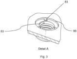
- Fig. 3 depicts the detail A of Fig. 2 .
- the blocking recesses 83 are configured as wedge-shaped recesses. They are distributed in an equidistant manner on a periphery (circumference) of a depression 86 for receiving the collar 7.
- the thread 63 in the blind hole is left-handed.
- the thread 63 is a modified buttress (sawtooth) thread.
Landscapes
- Engineering & Computer Science (AREA)
- Mechanical Engineering (AREA)
- Food Science & Technology (AREA)
- Food-Manufacturing Devices (AREA)
Abstract
A container device (1) for a kitchen appliance for processing food comprising:
- a lid (2),
- a container (3),
- a processing tool (4),
- a supporting plug (5),
wherein the processing tool (4) is rotatably mounted on the supporting plug (5), characterised in that the supporting plug (5) is configured to be releasably attachable to the container (3).
- a lid (2),
- a container (3),
- a processing tool (4),
- a supporting plug (5),
wherein the processing tool (4) is rotatably mounted on the supporting plug (5), characterised in that the supporting plug (5) is configured to be releasably attachable to the container (3).
Description
- The present invention relates to a container device for a kitchen appliance for processing food and a kitchen appliance comprising such a container device.
- Container devices for kitchen appliances for processing food are known in the art. They are usually used with small kitchen appliances for processing food such as hand blenders, hand mixers, choppers, liquidizers, compact food processors and the like. These appliances are mainly hand-held and are then employed as drive means (drive units) for driving the working tool of the container devices and are attachable on the top of their containers, namely on their lids. Hence, in these containers (bowls) working tools are driven from above and arranged on bearing plugs (pins) on their bottom where they can rotate. As the bowls are manufactured by injection moulding, the bearing plugs are usually integrated in the bottom of the containers, in other words they are made in one piece with the containers. That being said, the material of the plug is the same as the material of the bowl. These materials specifically don't have good sliding properties. Therefore, as the working tool in the form of a knife with blades rotates on the plug a lot of heat is generated so that both can even melt and weld to each other which leads to a permanent damage.
- There are solutions on the market which include bowls made of two or more parts. In this case, the metal plug is moulded into the plastic bowl. Manufacturing of such bowls is extremely expensive. Moreover, the plug is permanently integrated into the bowl. After a while the plug can wear out. As the metal plug is integrated, the whole bowl has to be replaced which is inconvenient in terms of costs and sustainability.
- Therefore, there is a need for a solution that would comprise a replaceable plug. Moreover, the working tool should rotate on the plug as smoothly as possible. That being said, the plug should be made of a material with good sliding characteristics.
- It is an object of the present invention to improve functionality and usability of a container device for a kitchen appliance and increase its service life. At the same time repairability and sustainability should also be improved.
- The object is achieved by a container device according to the features of claim 1. Advantageous embodiments that can be implemented by themselves or in combination are described in dependent claims.
- The invention relates to a container device for a kitchen appliance for processing food comprising:
- a lid,
- a container,
- a processing tool,
- a supporting plug,
- The lid comprises a drive inlet to which a drive means can be attached. The drive means causes the processing tool to rotate via a coupling means. During operation the supporting plug is attached to the container and the processing tool slides in a rotatable manner on the supporting plug.
- Preferably, the supporting plug is configured to be attachable in a form-fitting manner and/or force-fitting manner. It is configured to be attachable by means of a threaded connection.
- Advantageously, the threaded connection is formed as a modified buttress (sawtooth) thread. That being said, the threads of the supporting plug and the recess respectively comprise such a thread. This has the effect that stresses in the threaded connection are significantly reduced. So, the threaded connection is more durable and lasts longer.
- According to one embodiment, the supporting plug comprises a collar. The collar has an annular (ring) shape. This ring is configured so that the processing tool slides on it in a rotating manner. Since the supporting plug is made of material with good sliding properties, its wear is significantly reduced.
- In a preferred embodiment, the supporting plug can be blocked by a blocking means. The blocking means is formed by at least one blocking protrusion of the supporting plug and at least one blocking recess which is positioned on the bottom of the container. The effect is blocking of the supporting plug against unintended untightening and hence removing of the plug.
- Preferebly, the blocking means are realized as three locking recesses and the corresponding blocking protrusions on the supporting plug.
- According to one preferred embodiment, the supporting plug comprises manipulation means. The manipulations means are preferably configured as grooves adapted for positioning and fixing a special tool. This special tool is configured for tightening the supporting plug into the bottom of the container and untightening it. In this way the supporting plug is easily replaceable.
- Advantageously, the container comprises a recess. The recess is positioned on the bottom, in the centre thereof. The internal wall of the recess is provided with a thread and forms part of a threaded connection.
- In an advantageous solution, the supporting plug is preferably made of a plastic material (e.g. polymer) that is different from the material the container is made of and which has good sliding characteristics. Such materials are for instance polyoxymethylene (POM), polyamide (PA), polyether ether ketone (PEEK) and polybutylene terephthalate (PBT). Of course, all of these materials must have food grade properties in order to be used for food processing.
- The supporting plug can also be made of food grade metal, preferably stainless steel. In this case it can be machined (by turning) or sintered.
- Optionally, the supporting plug has a cylindrical to frustoconical shape. A lower part is cylindrical and extends longitudinally to an upper part of a substantially frustoconical shape. The supporting plug comprises an (internal) cavity so that it is hollow.
- Specifically, the processing tool is preferably a cutting tool, i.e. a knife, provided with typically 2 or 4 blades. The processing tool can also be realized as a mixing/stirring tool or a kneading tool.
- Preferably, the processing tool rotates counterclockwise. It slides on the collar of the supporting plug. As the thread of the supporting plug is left-handed, the processing tool tightens it into the recess of the container. Of course, when need be or if the tool rotates clockwise, the thread can also be adapted to be right-handed.
- Specifically, the processing tool comprises a braking member which is arranged in its cavity. The braking member has a ring shape and is configured to slow down and stop rotation of the tool as fast as possible, when the lid is removed from the container of the container device. This represents a safety feature for preventing injuries and material damage.
- A horizontal cross-section of the container can be circular. The inner wall of the container can be provided with flow breakers. The effect is a disruption (breakage) of the laminar flow of the foodstuff (i.e. introducing turbulence and swirling effect) during the processing operation. Such disruption improves the process and results in a more uniform mixing, blending or chopping of the food. Such modifications to the geometry of the container, namely flow breakers, include inward protrusions, such as ribs, ridges and the like.
- In a vertical cross-section the container has a substantially frustoconical shape. According to one embodiment, the container is preferably made of a plastic material, in particular Tritan, which is food-grade and has good mechanical properties.
- Terms such as "upper", "lower", "inner", "outer", "vertical", "horizontal" and the like indicate positions and orientations during the normal use and normal arranging of the parts of the container device.
- A second aspect of the invention is a kitchen appliance comprising the container device according to claim 1 and the dependent claims.
-
-
Fig. 1 is a vertical cross-section of the container device -
Fig. 2 is an isometric view of the container device with the container in a cross-section -
Fig. 3 is an isometric detail view of the detail A ofFig. 2 -
Fig. 1 depicts a container device 1 for a kitchen appliance for processing food according to one embodiment of the invention. Acontainer 3 is covered by alid 2. Thelid 2 acccomodates a drive inlet 9 to which a drive means (not shown) can be attached. The drive means (e.g. drive unit of a hand-held blender or a hand mixer) comprising an electric motor causes aprocessing tool 4 to rotate via a coupling means 4c. The coupling means 4c comprises a coupler (not shown) which is part of theprocessing tool 4 and a counter-coupler (not shown) which is part of the drive inlet 9. The coupler and the counter-coupler are engaged, when thelid 2 is attached to thecontainer 3. Theprocessing tool 4 is rotatably mounted on the supportingplug 5. During use the supportingplug 5 is threaded into thecontainer 3 by means of a threadedconnection 6 and theprocessing tool 4 rotates (slides) on the supportingplug 5, more specifically on itscollar 7. In a cavity of theprocessing tool 4 abraking member 4b is arranged. The brakingmember 4b has a ring shape and is configured to slow down and stop rotation of theprocessing tool 4 as fast as possible, when thelid 2 is removed from thecontainer 3 of the container device 1. - The supporting
plug 5 can be blocked by a blocking means 8. The blocking means 8 is formed by at least one blockingprotrusion 85 of the supportingplug 5 and at least oneblocking recess 83 which is positioned on the bottom of thecontainer 3. As shown inFig. 3 (detail A ofFig. 2 ) the blocking recesses 83 are preferably three. Theprocessing tool 4 rotates about the centre axis X-X in a counterclockwise direction. As thethread processing tool 4 the supportingplug 5 is tightened into therecess 3a (blind hole or blind bore) of thecontainer 3. The blocking recesses 83 and the blockingprotrusions 85 prevent the supportingplug 5 from untightening (in a clockwise direction) and removing from the bottom of thecontainer 3. - The
processing tool 4 is configured as a knife and comprises at least oneblade 4a, preferably two blades. -
Fig. 2 shows the container device 1 according to one embodiment of the invention. A curve TD shows a tightening direction of the supportingplug 5. - During normal use - when the supporting
plug 5 is attached to the bottom of the container 3 - thecollar 7 is substantially flush with the surface of the container bottom. The supportingplug 5 comprises manipulation means 10. The manipulations means 10 are preferably configured as substantially vertical grooves which are arranged equidistantly and adapted for positioning and fixing a special tool (not shown). This special tool is configured for tightening the supportingplug 5 to the bottom of thecontainer 3 and for untightening the supportingplug 5. In this way a user is prevented from removing the supportingplug 5 without using a special tool. - An inner wall of the
container 3 is provided with flow breakers. -
Fig. 3 depicts the detail A ofFig. 2 . The blocking recesses 83 are configured as wedge-shaped recesses. They are distributed in an equidistant manner on a periphery (circumference) of adepression 86 for receiving thecollar 7. Thethread 63 in the blind hole is left-handed. - As well as the
thread 65 of the supportingplug 5, thethread 63 is a modified buttress (sawtooth) thread. -
- 1 container device
- 2 lid
- 3 container
- 3a recess
- 4 processing tool
- 4a blade (of processing tool)
- 4b braking member
- 4c coupling means
- 5 supporting plug
- 6 threaded connection
- 63 thread (container)
- 65 thread (supporting plug)
- 7 collar
- 8 blocking means
- 83 blocking recess
- 85 blocking protrusion
- 86 depression
- 9 drive inlet
- 10 manipulation means
- TD tightening direction
- X-X centre axis
Claims (15)
- A container device (1) for a kitchen appliance for processing food comprising:- a lid (2),- a container (3),- a processing tool (4),- a supporting plug (5),wherein the processing tool (4) is rotatably mounted on the supporting plug (5), characterised in that the supporting plug (5) is configured to be releasably attachable to the container (3).
- Container device (1) according to claim 1, characterised in that the supporting plug (5) is configured to be attachable in a form-fitting manner and/or force-fitting manner.
- Container device (1) according to claim 1 or 2, characterised in that the supporting plug (5) is configured to be attachable by means of a threaded connection (6).
- Container device (1) according to claim 3, characterised in that the threaded connection (6) is formed as a modified buttress thread.
- Container device (1) according to any of the preceding claims, characterised in that the supporting plug (5) comprises a collar (7).
- Container device (1) according to claim 5, characterised in that the processing tool (4) slides on the collar (7).
- Container device (1) according to any of the preceding claims, characterised in that the supporting plug (5) can be blocked by a blocking means (8).
- Container device (1) according to claim 7, characterised in that the blocking means (8) is formed by at least one blocking protrusion (85).
- Container device (1) according to claims 7 or 8, characterised in that the blocking means (8) is formed by at least one blocking recess (83).
- Container device (1) according to any of the preceding claims, characterised in that the supporting plug (5) comprises manipulation means (10).
- Container device (1) according to any of the preceding claims, characterised in that the container (3) comprises a recess (3a).
- Container device (1) according to any of the preceding claims, characterised in that the supporting plug (5) is made of polyoxymethylene (POM), polyamide (PA), polyether ether ketone (PEEK) or polybutylene terephthalate (PBT).
- Container device (1) according to any of the preceding claims, characterised in that the container (3) is preferably made of a plastic material, in particular Tritan.
- Container device (1) according to any of the preceding claims, characterised in that the processing tool (4) comprises a braking member (4b).
- Kitchen appliance comprising the container device (1) according to any of the preceding claims.
Priority Applications (1)
| Application Number | Priority Date | Filing Date | Title |
|---|---|---|---|
| EP23219833.3A EP4573993A1 (en) | 2023-12-22 | 2023-12-22 | Container device for a kitchen appliance |
Applications Claiming Priority (1)
| Application Number | Priority Date | Filing Date | Title |
|---|---|---|---|
| EP23219833.3A EP4573993A1 (en) | 2023-12-22 | 2023-12-22 | Container device for a kitchen appliance |
Publications (1)
| Publication Number | Publication Date |
|---|---|
| EP4573993A1 true EP4573993A1 (en) | 2025-06-25 |
Family
ID=89321551
Family Applications (1)
| Application Number | Title | Priority Date | Filing Date |
|---|---|---|---|
| EP23219833.3A Pending EP4573993A1 (en) | 2023-12-22 | 2023-12-22 | Container device for a kitchen appliance |
Country Status (1)
| Country | Link |
|---|---|
| EP (1) | EP4573993A1 (en) |
Citations (3)
| Publication number | Priority date | Publication date | Assignee | Title |
|---|---|---|---|---|
| US6641298B2 (en) * | 2000-03-17 | 2003-11-04 | Braun Gmbh | Processing container for foodstuffs |
| US20080223965A1 (en) * | 2005-10-19 | 2008-09-18 | Koninklijke Philips Electronics N.V. | Device for Chopping Food, in Particular Pieces of Ice |
| US20210267417A1 (en) * | 2018-09-24 | 2021-09-02 | Koninklijke Philips N.V. | Kitchen apparatus and method for spiralizing a foodstuff |
-
2023
- 2023-12-22 EP EP23219833.3A patent/EP4573993A1/en active Pending
Patent Citations (3)
| Publication number | Priority date | Publication date | Assignee | Title |
|---|---|---|---|---|
| US6641298B2 (en) * | 2000-03-17 | 2003-11-04 | Braun Gmbh | Processing container for foodstuffs |
| US20080223965A1 (en) * | 2005-10-19 | 2008-09-18 | Koninklijke Philips Electronics N.V. | Device for Chopping Food, in Particular Pieces of Ice |
| US20210267417A1 (en) * | 2018-09-24 | 2021-09-02 | Koninklijke Philips N.V. | Kitchen apparatus and method for spiralizing a foodstuff |
Similar Documents
| Publication | Publication Date | Title |
|---|---|---|
| US7681817B2 (en) | Food processor | |
| US9545175B2 (en) | Food processor with attachment | |
| US20170332843A1 (en) | Chopping accessory, chopping unit and domestic appliance for chopping | |
| US11877696B2 (en) | Food processor | |
| EP2572614A1 (en) | Blender with varying internally and externally shaped container | |
| CA2519661A1 (en) | Mixer with optional faucet | |
| CN104013317A (en) | Food processor | |
| US20180049592A1 (en) | Kitchen Appliance for Processing Foodstuff | |
| CN105578937B (en) | Method for installing the instrument for kitchen utensils | |
| KR20180014751A (en) | Grinder attachment for blender systems | |
| EP3373786B1 (en) | Safety bearing arrangement and food processing device | |
| JP6626044B2 (en) | Cooking device | |
| EP3517002A1 (en) | Electric blender | |
| US20190239694A1 (en) | Food processor having detachable spring-loaded lid | |
| US3335772A (en) | Comminuting attachment for hand mixer | |
| US20230341165A1 (en) | Food processing tool | |
| KR100396355B1 (en) | A turning device for food processing cutting machines | |
| US20030132236A1 (en) | Working container for receiving and processing foodstuffs | |
| US20240226829A1 (en) | Blender and method of blending | |
| CN115700099B (en) | Food preparation appliance with multi-part accessory | |
| EP3845101B1 (en) | Container with handle for a kitchen appliance | |
| EP2767203B1 (en) | Hand blender | |
| CN100508852C (en) | Kitchen appliance comprising a special mounting device | |
| CN105682518B (en) | Tools with separating ribs for kitchen utensils | |
| CN120360428A (en) | Kitchen appliance with screw cutter |
Legal Events
| Date | Code | Title | Description |
|---|---|---|---|
| PUAI | Public reference made under article 153(3) epc to a published international application that has entered the european phase |
Free format text: ORIGINAL CODE: 0009012 |
|
| STAA | Information on the status of an ep patent application or granted ep patent |
Free format text: STATUS: THE APPLICATION HAS BEEN PUBLISHED |
|
| AK | Designated contracting states |
Kind code of ref document: A1 Designated state(s): AL AT BE BG CH CY CZ DE DK EE ES FI FR GB GR HR HU IE IS IT LI LT LU LV MC ME MK MT NL NO PL PT RO RS SE SI SK SM TR |
|
| STAA | Information on the status of an ep patent application or granted ep patent |
Free format text: STATUS: REQUEST FOR EXAMINATION WAS MADE |
|
| 17P | Request for examination filed |
Effective date: 20260102 |