EP4573958A1 - Upper and shoe - Google Patents
Upper and shoe Download PDFInfo
- Publication number
- EP4573958A1 EP4573958A1 EP22959490.8A EP22959490A EP4573958A1 EP 4573958 A1 EP4573958 A1 EP 4573958A1 EP 22959490 A EP22959490 A EP 22959490A EP 4573958 A1 EP4573958 A1 EP 4573958A1
- Authority
- EP
- European Patent Office
- Prior art keywords
- region
- yarns
- shoe
- base member
- holes
- Prior art date
- Legal status (The legal status is an assumption and is not a legal conclusion. Google has not performed a legal analysis and makes no representation as to the accuracy of the status listed.)
- Pending
Links
Images





Classifications
-
- A—HUMAN NECESSITIES
- A43—FOOTWEAR
- A43B—CHARACTERISTIC FEATURES OF FOOTWEAR; PARTS OF FOOTWEAR
- A43B23/00—Uppers; Boot legs; Stiffeners; Other single parts of footwear
- A43B23/02—Uppers; Boot legs
- A43B23/0205—Uppers; Boot legs characterised by the material
- A43B23/0235—Different layers of different material
-
- A—HUMAN NECESSITIES
- A43—FOOTWEAR
- A43B—CHARACTERISTIC FEATURES OF FOOTWEAR; PARTS OF FOOTWEAR
- A43B1/00—Footwear characterised by the material
- A43B1/0027—Footwear characterised by the material made at least partially from a material having special colours
-
- A—HUMAN NECESSITIES
- A43—FOOTWEAR
- A43B—CHARACTERISTIC FEATURES OF FOOTWEAR; PARTS OF FOOTWEAR
- A43B1/00—Footwear characterised by the material
- A43B1/02—Footwear characterised by the material made of fibres or fabrics made therefrom
- A43B1/028—Synthetic or artificial fibres
-
- A—HUMAN NECESSITIES
- A43—FOOTWEAR
- A43B—CHARACTERISTIC FEATURES OF FOOTWEAR; PARTS OF FOOTWEAR
- A43B1/00—Footwear characterised by the material
- A43B1/02—Footwear characterised by the material made of fibres or fabrics made therefrom
- A43B1/04—Footwear characterised by the material made of fibres or fabrics made therefrom braided, knotted, knitted or crocheted
-
- A—HUMAN NECESSITIES
- A43—FOOTWEAR
- A43B—CHARACTERISTIC FEATURES OF FOOTWEAR; PARTS OF FOOTWEAR
- A43B23/00—Uppers; Boot legs; Stiffeners; Other single parts of footwear
- A43B23/02—Uppers; Boot legs
- A43B23/0245—Uppers; Boot legs characterised by the constructive form
-
- D—TEXTILES; PAPER
- D04—BRAIDING; LACE-MAKING; KNITTING; TRIMMINGS; NON-WOVEN FABRICS
- D04B—KNITTING
- D04B21/00—Warp knitting processes for the production of fabrics or articles not dependent on the use of particular machines; Fabrics or articles defined by such processes
- D04B21/10—Open-work fabrics
- D04B21/12—Open-work fabrics characterised by thread material
-
- D—TEXTILES; PAPER
- D10—INDEXING SCHEME ASSOCIATED WITH SUBLASSES OF SECTION D, RELATING TO TEXTILES
- D10B—INDEXING SCHEME ASSOCIATED WITH SUBLASSES OF SECTION D, RELATING TO TEXTILES
- D10B2331/00—Fibres made from polymers obtained otherwise than by reactions only involving carbon-to-carbon unsaturated bonds, e.g. polycondensation products
- D10B2331/04—Fibres made from polymers obtained otherwise than by reactions only involving carbon-to-carbon unsaturated bonds, e.g. polycondensation products polyesters, e.g. polyethylene terephthalate [PET]
-
- D—TEXTILES; PAPER
- D10—INDEXING SCHEME ASSOCIATED WITH SUBLASSES OF SECTION D, RELATING TO TEXTILES
- D10B—INDEXING SCHEME ASSOCIATED WITH SUBLASSES OF SECTION D, RELATING TO TEXTILES
- D10B2401/00—Physical properties
- D10B2401/14—Dyeability
-
- D—TEXTILES; PAPER
- D10—INDEXING SCHEME ASSOCIATED WITH SUBLASSES OF SECTION D, RELATING TO TEXTILES
- D10B—INDEXING SCHEME ASSOCIATED WITH SUBLASSES OF SECTION D, RELATING TO TEXTILES
- D10B2403/00—Details of fabric structure established in the fabric forming process
- D10B2403/02—Cross-sectional features
- D10B2403/021—Lofty fabric with equidistantly spaced front and back plies, e.g. spacer fabrics
- D10B2403/0213—Lofty fabric with equidistantly spaced front and back plies, e.g. spacer fabrics with apertures, e.g. with one or more mesh fabric plies
-
- D—TEXTILES; PAPER
- D10—INDEXING SCHEME ASSOCIATED WITH SUBLASSES OF SECTION D, RELATING TO TEXTILES
- D10B—INDEXING SCHEME ASSOCIATED WITH SUBLASSES OF SECTION D, RELATING TO TEXTILES
- D10B2403/00—Details of fabric structure established in the fabric forming process
- D10B2403/02—Cross-sectional features
- D10B2403/022—Lofty fabric with variably spaced front and back plies, e.g. spacer fabrics
-
- D—TEXTILES; PAPER
- D10—INDEXING SCHEME ASSOCIATED WITH SUBLASSES OF SECTION D, RELATING TO TEXTILES
- D10B—INDEXING SCHEME ASSOCIATED WITH SUBLASSES OF SECTION D, RELATING TO TEXTILES
- D10B2501/00—Wearing apparel
- D10B2501/04—Outerwear; Protective garments
- D10B2501/043—Footwear
Definitions
- the present disclosure relates to an upper and a shoe including the upper.
- the knitted upper includes a cloth-like base member.
- Patent Literature 1 JP 2016-182350 A
- yarns of different materials do not have the same physical properties, such as strength, colorability, and stretchability, there is a problem that when two or more types of colors are applied to a base member by using yarns of different materials as in the past, it is necessary to use a yarn having inferior physical properties.
- the present disclosure has been made in view of the above, and a purpose thereof is to obtain an upper in which two or more types of colors can be applied to at least a partial region of a base member without using a yarn having inferior physical properties.
- an upper of a shoe comprising: a base member being a knitted fabric, wherein the base member includes a surface layer facing an outside of the upper, the surface layer includes a first region formed by a plurality of yarns, and a second region formed by a plurality of yarns and having a higher disposition density of the yarns than the first region, the yarns of the first region and the yarns of the second region are of the same material, and a plurality of colors is applied to the second region.
- An upper according to the present disclosure has an effect that two or more types of colors can be applied to at least a partial region of a base member without using a yarn having inferior physical properties.
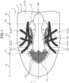
- FIG. 1 is a developed view illustrating an upper 2 of a shoe 1 according to a first embodiment of the present disclosure.
- FIG. 1 only the shoe 1 for a left foot is illustrated. Since the shoe 1 has a left-right symmetrical structure for a left foot and a right foot, only the shoe 1 for a left foot is described in the present embodiment, and the description of the shoe 1 for a right foot is omitted.
- a direction in which a shoe center axis C, which is a perpendicular line passing through the center of the shoe 1 in a plan view of the shoe 1, extends is referred to as a fore-rear direction
- a direction orthogonal to the fore-rear direction in a plan view of the shoe 1 is referred to as a foot width direction.
- a direction from the heel toward the toe of the shoe 1 in the fore-rear direction is referred to as a fore side
- a direction from the toe toward the heel of the shoe 1 in the fore-rear direction is referred to as a rear side.
- a median side of a foot in the anatomical position is referred to as a medial foot side
- the side opposite to the median side of the foot in the anatomical position is referred to as a lateral foot side. That is, the side closer to the median line in the anatomical position is referred to as the medial foot side, and the side farther from the median line in the anatomical position is referred to as the lateral foot side.
- a vertical direction means a direction orthogonal to both the fore-rear direction and the foot width direction unless otherwise specified.
- the upper 2 includes an upper forefoot portion R1 that covers a fore foot position of a foot of a wearer with a standard body shape, an upper midfoot portion R2 that covers a midfoot position of a foot of a wearer with a standard body shape, and an upper rearfoot portion R3 that covers a rear foot position of a foot of a wearer with a standard body shape. From the fore side to the rear side of the upper 2, the upper forefoot portion R1, the upper midfoot portion R2, and the upper rearfoot portion R3 are connected in order.
- a line along the foot width direction passing through a position corresponding to about 30% to 40% of the dimension of the upper 2 from the fore end of the upper 2 in the fore-rear direction is defined as a first boundary line S1
- a line along the foot width direction passing through a position corresponding to about 75% to 85% of the dimension of the upper 2 from the fore end of the upper 2 in the fore-rear direction is defined as a second boundary line S2.
- the first boundary line S1 is a line roughly along the MP joint of a wearer with a standard body shape.
- the second boundary line S2 is a line roughly along the Chopart joint of a wearer with a standard body shape.
- the upper forefoot portion R1 is positioned on the fore side of the first boundary line S1.
- the upper midfoot portion R2 is positioned between the first boundary line S1 and the second boundary line S2.
- the upper rearfoot portion R3 is positioned behind the second boundary line S2.
- FIG. 2 is a perspective view illustrating the shoe 1 according to the first embodiment of the present disclosure.
- the shoe 1 is preferably a running shoe but may be a shoe for other sports, a walking shoe, a climbing shoe, or the like.
- the shoe 1 includes an upper 2 and a sole 3.
- the upper 2 is positioned above the sole 3.
- the upper 2 includes a base member 20, a shoe tongue 23, and a shoelace 24.
- the base member 20 covers an instep side part of a foot of a wearer.
- a foot insertion opening 20a and a throat portion 20b are disposed on the upper portion of the base member 20.
- the foot insertion opening 20a is an opening for inserting the foot of the wearer into the base member 20.
- the throat portion 20b is an opening communicating with the foot insertion opening 20a and extending to the fore side from the foot insertion opening 20a.
- a plurality of string passing portions 20c spaced apart from each other in the fore-rear direction is disposed.
- FIG. 2 illustrates only the string passing portions 20c disposed on the lateral-foot-side side edge of the throat portion 20b.
- the string passing portions 20c are only required to allow the shoelace 24 to pass through.
- the string passing portions 20c are, for example, through holes that pass through the base member 20 in the thickness direction of the base member 20.
- the shoe tongue 23 is a member for protecting the instep of the wearer.
- the shoe tongue 23 covers the throat portion 20b inside the base member 20.
- the shoe tongue 23 is fixed to the base member 20 by stitching, welding, bonding, or a combination thereof.
- the base member 20 and the shoe tongue 23 are preferably a knitted fabric made by forming yarns into chains and interlocking the chain-shaped portions to form a cloth, but may be a woven fabric, a braided fabric, or the like.
- the base member 20 and the shoe tongue 23 are preferably a double raschel warp knitted fabric knitted with polyester yarn.
- the shoelace 24 is a string-like member that is alternately passed through the string passing portions 20c disposed on one side edge of the throat portion 20b in the foot width direction and the string passing portions 20c disposed on the other side edge in the foot width direction.
- the shoelace 24 is detachably attached to the base member 20.
- the upper 2 including the shoe tongue 23 and the shoelace 24 is described as an example, but the upper 2 may have a monosock structure in which a portion corresponding to the shoe tongue 23 is integrated with an ankle portion of the base member 20.
- a hook-and-loop fastener may be used instead of the shoelace 24 to bring the base member 20 into close contact with the foot. If a hook-and-loop fastener is used to bring the base member 20 into close contact with the foot, the string passing portions 20c are not disposed in the base member 20.
- the sole 3 is positioned below the upper 2.
- the sole 3 covers the sole of the wearer.
- the sole 3 is fixed to the base member 20 by stitching, welding, bonding, or a combination thereof.
- the sole 3 includes an outsole 30 and a midsole 31.
- the lower surface of the outsole 30 serves as a ground contact surface 30a to be contacted on the ground.
- the midsole 31 is positioned on the upper surface of the outsole 30 and has a cushioning property. Note that the outsole 30 may be integrated with the midsole 31.
- the outsole 30 integrated with the midsole 31 is also referred to as a "unisole".
- the sole 3 includes an inner sole that covers the lower opening of the base member 20.
- the inner sole is fixed to the upper surface of the midsole 31 by bonding or welding.
- the inner sole is fixed to the lower edge of the base member 20 by stitching.
- the shoe 1 may include an insole. If the shoe 1 includes an insole, the insole is installed on the sole 3 inside the upper 2.
- the sole 3 may have a structure in which the inner sole is omitted.
- the base member 20 includes the upper forefoot portion R1, the upper midfoot portion R2, and the upper rearfoot portion R3. As illustrated in FIG. 2 , the base member 20 is disposed over the entire region of the upper 2 other than the shoe tongue 23 and the shoelace 24.
- the base member 20 is a single member in the present embodiment, but may be divided into a plurality of members. When the base member 20 is divided into a plurality of members, the base member 20 may be divided, for example, into a portion corresponding to the upper forefoot portion R1, a portion corresponding to the upper midfoot portion R2, and a portion corresponding to the upper rearfoot portion R3. The divided portions are connected by stitching, welding, bonding, or a combination thereof.
- FIG. 3 is a cross-sectional view taken along line III-III in FIG. 2 .
- FIG. 4 is a cross-sectional view taken along line IV-IV in FIG. 2 .
- FIG. 5 is a cross-sectional view taken along line V-V in FIG. 2 .
- FIG. 6 is a cross-sectional view taken along line VI-VI in FIG. 2 .
- the base member 20 is a cloth-like member including a plurality of layers.
- the base member 20 includes a surface layer 20d facing the outside of the upper 2, a back layer 20e facing the inside of the upper 2, and an intermediate layer 20f disposed between the surface layer 20d and the back layer 20e.
- the base member 20 has three layers in the present embodiment, but is only required to have two or more layers.
- the back layer 20e is disposed with a gap from the surface layer 20d in the thickness direction of the base member 20.
- the intermediate layer 20f connects the surface layer 20d and the back layer 20e.
- the intermediate layer 20f is alternately and repeatedly connected to the surface layer 20d and the back layer 20e.
- FIG. 7 is a plan view of the surface layer 20d when viewed from an arrow X1 in FIG. 3 .
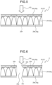
- FIG. 8 is a plan view of the surface layer 20d when viewed from an arrow X2 in FIG. 4 .
- FIG. 9 is a plan view of the surface layer 20d when viewed from an arrow X3 in FIG. 5 .
- FIG. 10 is a plan view of the surface layer 20d when viewed from an arrow X4 in FIG. 6 .
- the base member 20 is a knitted fabric in which a plurality of yarns 20g and 20h is knitted. In the present embodiment, the base member 20 is a knitted fabric formed by warp knitting.
- the surface layer 20d includes a first region 21 illustrated in FIGS. 7 and 8 and a second region 22 illustrated in FIGS. 9 and 10 .
- the first region 21 is a region formed by the yarns 20g and 20h.
- the first region 21 is a region formed by arranging only a plurality of knitting stitches 20i.
- the yarn 20h is disposed only in the back layer 20e in the first region 21, and extends along the back layer 20e.
- the second region 22 is a region formed by the yarns 20g and 20h and having a higher disposition density of the yarns 20g and 20h than the first region 21.
- the second region 22 is a region formed by arranging the knitting stitches 20i and disposing the yarn 20h formed independently of the knitting stitches 20i.
- FIGS. 9 and 10 illustrate that a part of the yarn 20g forming the knitting stitches 20i overlapping with the yarn 20h in a plan view is deleted in order to clarify the position of the yarn 20h, but in practice, the yarn 20g also exists in the part overlapping with the yarn 20h in a plan view.
- a part of the yarn 20h is lifted from the back layer 20e to the surface layer 20d in the second region 22, and is exposed on the surface of the upper 2. Note that, in each drawing illustrating the yarn 20h, the yarn 20h is illustrated as a broken line in order to clarify the position of the yarn 20h.
- the yarns 20g and 20h of the first region 21 and the yarns 20g and 20h of second region 22 are yarns made of one fiber, yarns obtained by bundling a plurality of fibers, twisted yarns, or the like.
- the yarns 20g and 20h of the first region 21 and the yarns 20g and 20h of the second region 22 are of the same material.
- the yarns 20g and 20h of the first region 21 and the yarns 20g and 20h of the second region 22 are formed solely from sulfonic acid group-free polyester fibers.
- the sulfonic acid group-free polyester fibers are preferably recycled polyester fibers, raw material colored polyester fibers, or recycled and raw material colored polyester fibers.
- each of the first region 21 and the second region 22 is disposed in the upper forefoot portion R1, the upper midfoot portion R2, and the upper rearfoot portion R3 of the base member 20.
- the first region 21 is disposed so as to surround a part of the periphery of the foot insertion opening 20a and the entire periphery of the throat portion 20b.
- the first region 21 is adjacent to the foot insertion opening 20a and the throat portion 20b.
- the second region 22 is disposed so as to surround the remainder of the periphery of the foot insertion opening 20a and the entire periphery of the first region 21.
- the second region 22 is adjacent to the remainder of the foot insertion opening 20a and the first region 21. Note that the positions of the first region 21 and the second region 22 are not limited to the illustrated example, and may be appropriately changed.
- a plurality of holes 21a is disposed in the first region 21.
- the shapes of the holes 21a in a plan view are not particularly limited, but are rhombuses in the present embodiment.
- the holes 21a are disposed in a fore side portion of the throat portion 20b, a medial foot side portion of the throat portion 20b, and a lateral foot side portion of the throat portion 20b of the base member 20. As illustrated in FIG. 4 , the holes 21a are through holes passing through the surface layer 20d, the back layer 20e, and the intermediate layer 20f in the first region 21 in the thickness direction of the base member 20.
- the position of an opening 21b opened in the surface layer 20d among the holes 21a in the first region 21 and, the position of an opening 21c opened in the back layer 20e among the holes 21a in the first region 21 are the same.
- the position of the opening 21b opened in the surface layer 20d among the holes 21a in the first region 21 and the position of the opening 21c opened in the back layer 20e among the holes 21a in the first region 21 coincide with each other when viewed along the thickness direction of the base member 20.
- a plurality of holes 22a is also disposed in the second region 22.
- the shapes of the holes 22a in a plan view are not particularly limited, but are rhombuses in the present embodiment.
- the holes 22a are disposed in a stripe 22d.
- the holes 22a are through holes passing through the surface layer 20d, the back layer 20e, and the intermediate layer 20f in the second region 22 in the thickness direction of the base member 20.
- the position of an opening 22b opened in the surface layer 20d among the holes 22a in the second region 22 and the position of an opening 22c opened in the back layer 20e among the holes 22a in the second region 22 are the same.
- the position of the opening 22b opened in the surface layer 20d among the holes 22a in the second region 22 and the position of the opening 22c opened in the back layer 20e among the holes 22a in the second region 22 coincide with each other when viewed along the thickness direction of the base member 20.
- the color of the first region 21 illustrated in FIG. 1 is the same over the entire region of the first region 21.
- the color of the first region 21 and the color of the second region 22 are different from each other.
- a plurality of colors is applied to the second region 22, a plurality of colors is applied.
- the second region 22 includes the stripe 22d, an edge portion 22e of the stripe 22d, and a standard portion 22f other than the stripe 22d and the edge portion 22e.
- the color of the stripe 22d, the color of the edge portion 22e, and the color of the standard portion 22f are different from each other.
- the upper 2 has four types of colors in the present embodiment, but preferably has three or more types of colors.
- color includes chromatic colors and achromatic colors, which are a series of colors ranging from white to gray to black.
- color difference includes a difference between a chromatic color and an achromatic color, a difference in hue in chromatic colors, a difference in saturation in chromatic colors, and a difference in brightness in achromatic colors. The color difference may be evaluated by appropriately selecting from known color systems, such as Munsell color system, XYZ color system, and Lab color space.
- the shades of the color of the stripe 22d may be changed stepwise, or may be the same over the entire region of the stripe 22d.
- the color of the edge portion 22e may be gradually changed to match the color of the standard portion 22f around the edge portion 22e.
- the shades of the color of the standard portion 22f may be changed stepwise, or may be the same over the entire region of the standard portion 22f.
- the shades of the color of the standard portion 22f may be changed stepwise along the foot width direction of the upper 2.
- the color of the standard portion 22f may be made lighter stepwise from the end of the upper 2 in the foot width direction toward the center of the upper 2 in the foot width direction.
- the yarn 20h different from the yarn 20g forming the knitting stitches 20i is colored and irregularly disposed on the surface layer 20d in the second region 22, and thereby a plurality of colors can be applied to the surface layer 20d in the second region 22. That is, as illustrated in FIGS. 3 to 6 , the yarn 20h disposed only on the back layer 20e in the first region 21 is disposed not only on the back layer 20e but also on the surface layer 20d in the second region 22, and thereby a plurality of colors can be applied to the surface layer 20d in the second region 22.
- the description that the yarn 20h is "disposed" on the surface layer 20d or the back layer 20e includes that the yarn 20h is knitted into the surface layer 20d or the back layer 20e, that the yarn 20h is overlaid without being knitted into the surface layer 20d or the back layer 20e, and the like.
- the first region 21 and the second region 22 can be formed in a single process using a warp knitting machine.
- the upper 2 includes the base member 20 that is a knitted fabric, and the base member 20 includes the surface layer 20d facing the outside of the upper 2.
- the surface layer 20d includes the first region 21 formed by the yarns 20g and 20h, and the second region 22 formed by the yarns 20g and 20h and having a higher disposition density of the yarns 20g and 20h than the first region 21.
- the yarns 20g and 20h of the first region 21 and the yarns 20g and 20h of the second region 22 are of the same material, and a plurality of colors is applied to the second region 22.
- the base member 20 is a knitted fabric formed by warp knitting.
- the base member needs to be dyed by post dyeing.
- a base member is made of yarns of the same material, only one color can be applied to the base member in post dyeing.
- two or more types of colors are applied to a base member by post-dyeing, two or more types of yarns of different materials need to be used in combination. In that case, it is necessary to use a yarn having inferior physical properties.
- the yarns 20g and 20h of the first region 21 and the yarns 20g and 20h of the second region 22 are of the same material, the yarns 20g and 20h of the first region 21 and the yarns 20g and 20h of the second region 22 are raw material colored, and the yarns 20h of the second region 22 can be freely disposed independently of the knitting stitches 20i, whereby two or more types of colors can be applied to the base member 20 without using a yarn having inferior physical properties.
- the base member 20 may be a knitted fabric formed by weft knitting.
- the base member 20 can be easily recycled.
- the yarns 20g and 20h of the first region 21 illustrated in FIGS. 3 and 4 and the yarns 20g and 20h of the second region 22 illustrated in FIGS. 5 and 6 are formed solely from sulfonic acid group-free polyester fibers.
- the physical properties, such as the strength of the base member 20 can be improved and the material cost of the base member 20 can be reduced as compared to the case in which the yarns 20g and 20h are formed from nylon fibers, cationic dyeable polyester (CDP), or the like.
- the sulfonic acid group-free polyester fibers used as the yarns 20g and 20h are recycled polyester fibers, since the amount of petroleum-derived raw material used for the base member 20 is reduced, it is possible to reduce the manufacturing cost of the base member 20 and the environmental loads.
- the raw material colored yarns 20g and 20h and the yarns 20g and 20h of two or more types of colors it is possible to apply two or more types of colors to the base member 20 without performing the post-dyeing of the base member 20.
- the sulfonic acid group-free polyester fibers used as the yarns 20g and 20h are raw material colored polyester fibers, since the amount of electricity and water used for dyeing the base member 20 can be reduced as compared to the case in which the base member 20 is post dyed, it is possible to reduce the manufacturing cost of the base member 20 and the environmental loads.
- the first region 21 is a region formed by arranging only the knitting stitches 20i as illustrated in FIGS. 7 and 8
- the second region 22 is a region formed by arranging the knitting stitches 20i and disposing the yarn 20h formed independently of the knitting stitches 20i as illustrated in FIGS. 9 and 10 .
- the colors of the second region 22 illustrated in FIG. 1 are changed stepwise. With this configuration, it is possible to widen the range of expression of the design of the upper 2.
- the holes 21a are disposed in the first region 21.
- the shapes of the holes 21a in a plan view are rhombuses, the upper 2 easily deforms by following the stretching and shrinking of the skin of the foot when a wearer of the shoe 1 performs an action such as running. Therefore, it is possible to ease the contact of the upper 2 with the foot and to prevent the occurrence of wrinkles in the upper 2.
- the base member 20 includes a plurality of layers includes the surface layer 20d facing the outside of the upper 2 and the back layer 20e facing the inside of the upper 2. With this configuration, it is possible for the layers to protect the foot of the wearer inside the upper 2. In particular, in the present embodiment, since the base member 20 has three layers including the intermediate layer 20f disposed between the surface layer 20d and the back layer 20e, it is possible to further protect the foot of the wearer.
- the material of the yarns 20g and 20h of the first region 21 and the material of the yarns 20g and 20h of the second region 22 are not limited to the above sulfonic acid group-free polyester fibers.
- the material of the yarns 20g and 20h of the first region 21 and the material of the yarns 20g and 20h of the second region 22 may be, for example, synthetic fibers made from polyester, polyamide, polyurethane, polyolefin, artificial protein, or the like, semisynthetic fibers made from acetate or the like, regenerated fibers made from rayon, cupra, or the like, natural fibers made from cotton, hemp, silk, wool, or the like, or inorganic fibers made from glass, metal, carbon, or the like.
- the upper 2 and the sole 3 may be formed from the same material.
- the upper 2 and the sole 3 may be formed from sulfonic acid group-free polyester fibers. With this configuration, since recycling of the entire shoe 1 is facilitated and the amount of petroleum-derived raw material used and the like is reduced, it is possible to reduce the manufacturing cost of the shoe 1 and the environmental loads.
- the upper 2 and the sole 3 may be formed from thermoplastic polyester elastomer. With this configuration, since the sole 3 having high resilience can be provided, it is possible to improve the functionality of the shoe 1 and to provide the shoe 1 that can be easily recycled.
- the upper 2 and the sole 3 may be formed from similar materials.
- similar material refers to a polymer material having a common monomer structure.
- the upper 2 may be formed from sulfonic acid group-free polyester fibers
- the sole 3 may be formed from thermoplastic polyester elastomer.
- FIG. 11 is a cross-sectional view illustrating the upper 2 of the shoe 1 according to a first modification of the first embodiment of the present disclosure and corresponds to a cross-sectional view taken along line IV-IV in FIG. 2 .
- the position of the opening 21b opened in the surface layer 20d among the holes 21a in the first region 21 and the position of the opening 21c opened in the back layer 20e among the holes 21a in the first region 21 are different from each other.
- the position of the opening 21b opened in the surface layer 20d among the holes 21a in the first region 21 and the position of the opening 21c opened in the back layer 20e among the holes 21a in the first region 21 are shifted from each other when viewed along the thickness direction of the base member 20.
- the holes 21a in the first region 21 are bottomed holes.
- the holes 21a in the first region 21 are bottomed holes, it is possible to secure the air permeability of the inside of the shoe 1.
- the holes 21a in the first region 21 are bottomed holes, it is possible to prevent foreign objects, such as dust and sand, from entering the inside of the shoe 1 through the holes 21a and to prevent the sock inside the shoe 1 from being seen from the outside of the shoe 1.
- the position of the opening 21b opened in the surface layer 20d among the holes 21a in the first region 21 and the position of the opening 21c opened in the back layer 20e among the holes 21a in the first region 21 are shifted from each other when viewed along the thickness direction of the base member 20, it is possible to obtain visual effects, such as a design effect by showing the pattern of the back layer 20e from the opening 21b in the surface layer 20d and a lenticular effect by slightly shifting the position of the opening 21b from the position of the opening 21c.
- FIG. 12 is a cross-sectional view illustrating the upper 2 of the shoe 1 according to a second modification of the first embodiment of the present disclosure and corresponds to a cross-sectional view taken along line VI-VI in FIG. 2 .
- the position of the opening 22b opened in the surface layer 20d among the holes 22a in the second region 22 and the position of the opening 22c opened in the back layer 20e among the holes 22a in the second region 22 are different from each other.
- the position of the opening 22b opened in the surface layer 20d among the holes 22a in the second region 22 and the position of the opening 22c opened in the back layer 20e among the holes 22a in the second region 22 are shifted from each other when viewed along the thickness direction of the base member 20.
- the holes 22a in the second region 22 are bottomed holes.
- the holes 22a in the second region 22 are bottomed holes, it is possible to secure the air permeability of the inside of the shoe 1.
- the holes 22a in the second region 22 are bottomed holes, whereby foreign objects, such as dust and sand, can be prevented from entering the inside of the shoe 1 through the holes 22a, and the sock inside the shoe 1 can be prevented from being seen from the outside of the shoe 1.
- the position of the opening 22b opened in the surface layer 20d among the holes 22a in the second region 22 and the position of the opening 22c opened in the back layer 20e among the holes 22a in the second region 22 are shifted from each other when viewed along the thickness direction of the base member 20, it is possible to obtain visual effects, such as a design effect by showing the pattern of the back layer 20e from the opening 22b in the surface layer 20d and a lenticular effect by slightly shifting the position of the opening 22b from the position of the opening 22c.
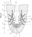
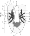
- FIG. 13 is a developed view illustrating an upper 2A of the shoe 1A according to the second embodiment of the present disclosure.
- the shoe 1A according to the second embodiment is different from the shoe 1 according to the first embodiment in that the shapes of holes 21a in a first region 21 are two or more types.
- the first region 21 includes a stretching region 21d adjacent to a throat portion 20b on the fore side of the throat portion 20b.
- the stretching region 21d extends in the foot width direction across the shoe center axis C.
- the holes 21a in the stretching region 21d are two or more types of holes having different shapes.
- the shapes of the holes 21a include the outer shapes of the holes 21a and the sizes of the holes 21a.
- the outer shapes of the holes 21a in the stretching region 21d are an identical rhombus, but the sizes of holes 21a in the stretching region 21d are different.
- the sizes of the holes 21a are reduced from the center of the first region 21 in the foot width direction toward the end of the first region 21 in the foot width direction.
- the holes 21a in the stretching region 21d is only required to be two or more types of holes in which at least one of the outer shapes of the holes 21a and the sizes of the holes 21a are different.
- the movement of the foot is different in each part of the foot.
- the holes 21a in the first region 21 are two or more types of holes having different shapes, it is possible to adjust the shapes of holes 21a in such a manner that upper 2A easily deforms by following the movement of the foot. Therefore, it is possible to ease the contact of the upper 2A with the foot and to prevent the occurrence of wrinkles in the upper 2A.
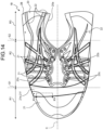
- FIG. 14 is a developed view illustrating an upper 2B of the shoe 1B according to the third embodiment of the present disclosure.
- FIG. 15 is a cross-sectional view taken along line XV-XV in FIG. 14 .
- the shoe 1B according to the third embodiment is different from the shoe 1 according to the first embodiment in that an intermediate layer 20f includes a region having different disposition densities of a yarn 20g and that the intermediate layer 20f includes a region having different thicknesses.
- a base member 20 of the upper 2B includes a first region 21 and a second region 22.
- the second region 22 is disposed from a lateral foot side portion of an upper midfoot portion R2 to a lateral foot side portion of an upper rearfoot portion R3, and is disposed from a medial foot side portion of the upper midfoot portion R2 to a medial foot side portion of the upper rearfoot portion R3.
- a part of the second region 22 is disposed from a rear side portion of the medial foot side edge of a throat portion 20b to the entire medial foot side edge of a foot insertion opening 20a.
- the intermediate layer 20f in the first region 21 includes a region having different disposition densities of the yarn 20g.
- the region having different disposition densities of the yarn 20g is referred to as a density change region 21e.
- the density change region 21e is schematically illustrated by a thick solid line.
- the shape of the density change region 21e in a plan view is not particularly limited, but is a substantially rectangular shape that is longer in the foot width direction than in the fore-rear direction in the present embodiment.
- the density change region 21e is not limited to the illustrated position, and may be appropriately changed.
- the disposition densities of the yarn 20g in the intermediate layer 20f in the density change region 21e are changed stepwise.
- the density of the yarn 20g in the intermediate layer 20f in the density change region 21e is increased from the center toward the end in the foot width direction.
- the left side of the drawing is the center side in the foot width direction
- the right side of the drawing is the end side in the foot width direction.
- the density of the yarn 20g in the intermediate layer 20f can be increased from the center toward the end in the foot width direction.
- the density of the yarn 20g in the intermediate layer 20f may be increased from the end toward the center in the foot width direction, or may be increased from one side toward the other side in the fore-rear direction.
- the intermediate layer 20f in the first region 21 includes a region having different thicknesses.
- the region of the intermediate layer 20f having different thicknesses is referred to as a thickness change region 21f.
- the thickness change region 21f is schematically illustrated by a thick solid line.
- the shape of the thickness change region 21f in a plan view is not particularly limited, but is a substantially rectangular shape that is longer in the foot width direction than in the fore-rear direction in the present embodiment.
- the thickness change region 21f coincides with the density change region 21e, but may be disposed at a position different from the density change region 21e. That is, the thickness change region 21f is not limited to the illustrated position, and may be appropriately changed.
- the thickness D of the intermediate layer 20f in the thickness change region 21f is changed stepwise.
- the thickness D of the intermediate layer 20f in the thickness change region 21f is increased from the center toward the end in the foot width direction.
- the thickness D of the intermediate layer 20f may be increased from the end toward the center in the foot width direction, or may be increased from one side toward the other side in the fore-rear direction.
- no holes 21a are disposed.
- holes 21a are disposed between adjacent hatched portions. That is, the portions in which the holes 21a are disposed and the portions in which no holes 21a are disposed are alternately disposed in the fore-rear direction on both sides in the foot width direction sandwiching the throat portion 20b in the first region 21.
- the material hardness is different between the portion with the intermediate layer 20f and the portion without the intermediate layer 20f. If the material hardness is different, the load is concentrated on a portion of the upper 2 having low material hardness when the foot is bent, and the upper 2B is likely to be folded, wrinkled, broken, or the like.
- the disposition densities of the yarn 20g in the intermediate layer 20f are changed stepwise, it is possible to disperse the load generated at the time of bending the foot or the like. Therefore, the folds and wrinkles of the upper 2B is less noticeable, the fit to the foot of the wearer can be improved, and the upper 2B is less likely to be broken.
- the thickness D of the intermediate layer 20f is changed stepwise, it is possible to achieve the effects described in paragraph 0066.
- the thickness D of the intermediate layer 20f is changed stepwise, it is possible to express a design having height differences in the thickness direction of the upper 2 and to create a visual effect with a three-dimensional effect.
- the thickness D of the intermediate layer 20f is changed stepwise and the back layer 20e is partially brought into contact with the foot, it is possible to improve the air permeability of the inside of the shoe 1B.
- FIG. 16 is a developed view illustrating an upper 2C of the shoe 1C according to the fourth embodiment of the present disclosure.
- the shoe 1C according to the fourth embodiment is different from the shoe 1 according to the first embodiment in that a base member 20 includes a third region 25.
- the base member 20 of the upper 2C includes the third region 25 formed by a plurality of yarns 20j.
- the third region 25 is hatched.
- the third region 25 is a region excluding a second region 22 in the hatched region.
- the third region 25 is disposed in a medial foot side portion of an upper midfoot portion R2.
- the material of the yarns 20j of the third region 25 is different from the material of yarns 20g and 20h of a first region 21 and the material of the yarns 20g and 20h of the second region 22.
- the yarn 20j of the third region 25 is formed from fibers other than sulfonic acid group-free polyester fibers.
- the base member 20 includes the third region 25 formed by the yarns 20j, and the material of the yarns 20j of the third region 25 is different from the material of the yarns 20g and 20h of the first region 21 and the yarns 20g and 20h of the second region 22.
- the third region 25 can be disposed at a portion at which different stretchability is required, such as the medial foot side portion of the upper midfoot portion R2, it is possible to improve the fit of the upper 2C to the foot of the wearer.
- the yarns 20j of the third region 25 may be of a material similar to the material of the yarns 20g and 20h of the first region 21 and the yarns 20g and 20h of the second region 22.
- the yarns 20g and 20h of the first region 21 and the yarns 20g and 20h of the second region 22 may be formed solely from sulfonic acid group-free polyester fibers
- the yarns 20j of the third region 25 may be formed from thermoplastic polyester elastomer.
- An upper according to a first aspect is an upper of a shoe, the upper includes:
- An upper according to a second aspect is the upper according to the first aspect, in which the yarns of the first region and the yarns of the second region are formed solely from sulfonic acid group-free polyester fibers.
- An upper according to a third aspect is the upper according to the first or second aspect, in which
- An upper according to a fourth aspect is the upper according to any one of the first to third aspects, in which a plurality of holes is disposed in the first region.
- An upper according to a fifth aspect is the upper according to the fourth aspect, in which the holes in the first region are two or more types of holes having different shapes.
- An upper according to a sixth aspect is the upper according to the fourth or fifth aspect, in which
- An upper according to a seventh aspect is the upper according to any one of the fourth to sixth aspects, in which the base member includes a plurality of layers including a back layer facing an inside of the upper.
- An upper according to an eighth aspect is the upper according to the seventh aspect, in which a position of an opening opened in the surface layer among the holes in the first region and a position of an opening opened in the back layer among the holes in the first region are different from each other.
- An upper according to a ninth aspect is the upper according to any one of the fourth to eighth aspects, in which the holes in the first region are bottomed holes.
- An upper according to a tenth aspect is the upper according to the seventh aspect, in which the base member has three layers including an intermediate layer disposed between the surface layer and the back layer.
- An upper according to an eleventh aspect is the upper according to the tenth aspect, in which the intermediate layer includes a region having different yarn disposition densities.
- An upper according to a twelfth aspect is the upper according to the tenth or eleventh aspect, in which the yarn disposition densities in the intermediate layer are changed stepwise.
- An upper according to a thirteenth aspect is the upper according to any one of the tenth to twelfth aspects, in which the intermediate layer includes a region having different thicknesses.
- An upper according to a fourteenth aspect is the upper according to any one of the tenth to thirteenth aspects, in which the thicknesses of the intermediate layer are changed stepwise.
- An upper according to a fifteenth aspect is the upper according to any one of the first to fourteenth aspects, in which
- An upper according to a 16 aspect is the upper according to the second aspect, in which the sulfonic acid group-free polyester fibers are recycled polyester fibers.
- An upper according to a seventeenth aspect is the upper according to the second aspect, in which the sulfonic acid group-free polyester fibers are raw material colored polyester fibers.
- An upper according to an eighteenth aspect is the upper according to any one of the first to seventeenth aspects, in which the colors of the second region are changed stepwise.
- An upper according to a nineteenth aspect is the upper according to any one of the first to eighteenth aspects, in which a color of the first region and the colors of the second region are different from each other.
- An upper according to a twentieth aspect is the upper according to any one of the first to nineteenth aspects, in which the upper has three or more types of colors.
- An upper according to a twenty first aspect is the upper according to any one of the first to twentieth aspects, in which the base member is a knitted fabric formed by warp knitting.
- a shoe according to a twenty second aspect includes the upper according to any one of claims 1 to 21; and a sole positioned below the upper.
Landscapes
- Engineering & Computer Science (AREA)
- Textile Engineering (AREA)
- Chemical & Material Sciences (AREA)
- Materials Engineering (AREA)
- Footwear And Its Accessory, Manufacturing Method And Apparatuses (AREA)
Abstract
Description
- The present disclosure relates to an upper and a shoe including the upper.
- As a conventional upper, a knitted upper is known (see, for example, Patent Literature 1). The knitted upper includes a cloth-like base member.
- As a method of applying a color to the base member of the knitted upper, post-dyeing, in which the base member is made and then dyed, is known. When two or more types of colors are applied to the base member by post-dyeing, two or more types of yarns of different materials need to be used in combination. That is, after the base member is made by knitting yarns of different materials, the yarns of different materials need to be dyed with different dyes.
- Patent Literature 1:
JP 2016-182350 A - Since yarns of different materials do not have the same physical properties, such as strength, colorability, and stretchability, there is a problem that when two or more types of colors are applied to a base member by using yarns of different materials as in the past, it is necessary to use a yarn having inferior physical properties.
- The present disclosure has been made in view of the above, and a purpose thereof is to obtain an upper in which two or more types of colors can be applied to at least a partial region of a base member without using a yarn having inferior physical properties.
- In order to solve the above problem and achieve the object, an upper of a shoe, the upper comprising: a base member being a knitted fabric, wherein the base member includes a surface layer facing an outside of the upper, the surface layer includes a first region formed by a plurality of yarns, and a second region formed by a plurality of yarns and having a higher disposition density of the yarns than the first region, the yarns of the first region and the yarns of the second region are of the same material, and a plurality of colors is applied to the second region.
- An upper according to the present disclosure has an effect that two or more types of colors can be applied to at least a partial region of a base member without using a yarn having inferior physical properties.
-
-
FIG. 1 is a developed view illustrating an upper of a shoe according to a first embodiment of the present disclosure. -
FIG. 2 is a perspective view illustrating the shoe according to the first embodiment of the present disclosure. -
FIG. 3 is a cross-sectional view taken along line III-III inFIG. 2 . -
FIG. 4 is a cross-sectional view taken along line IV-IV inFIG. 2 . -
FIG. 5 is a cross-sectional view taken along line V-V inFIG. 2 . -
FIG. 6 is a cross-sectional view taken along line VI-VI inFIG. 2 . -
FIG. 7 is a plan view of a surface layer when viewed from an arrow X1 inFIG. 3 . -
FIG. 8 is a plan view of the surface layer when viewed from an arrow X2 inFIG. 4 . -
FIG. 9 is a plan view of the surface layer when viewed from an arrow X3 inFIG. 5 . -
FIG. 10 is a plan view of the surface layer when viewed from an arrow X4 inFIG. 6 . -
FIG. 11 is a cross-sectional view illustrating an upper of a shoe according to a first modification of the first embodiment of the present disclosure and corresponds to a cross-sectional view taken along line IV-IV inFIG. 2 . -
FIG. 12 is a cross-sectional view illustrating an upper of a shoe according to a second modification of the first embodiment of the present disclosure and corresponds to a cross-sectional view taken along line VI-VI inFIG. 2 . -
FIG. 13 is a developed view illustrating an upper of a shoe according to a second embodiment of the present disclosure. -
FIG. 14 is a developed view illustrating an upper of a shoe according to a third embodiment of the present disclosure. -
FIG. 15 is a cross-sectional view taken along line XV-XV inFIG. 14 . -
FIG. 16 is a developed view illustrating an upper of a shoe according to a fourth embodiment of the present disclosure. - Hereinafter, embodiments of an upper and a shoe according to the present disclosure will be described in detail with reference to the drawings. Note that the present disclosure is not limited by the embodiments. In the following description, the same portions are denoted by the same reference signs, and redundant description will be omitted.
-
FIG. 1 is a developed view illustrating an upper 2 of ashoe 1 according to a first embodiment of the present disclosure. In the drawings includingFIG. 1 , only theshoe 1 for a left foot is illustrated. Since theshoe 1 has a left-right symmetrical structure for a left foot and a right foot, only theshoe 1 for a left foot is described in the present embodiment, and the description of theshoe 1 for a right foot is omitted. In the following description, a direction in which a shoe center axis C, which is a perpendicular line passing through the center of theshoe 1 in a plan view of theshoe 1, extends is referred to as a fore-rear direction, and a direction orthogonal to the fore-rear direction in a plan view of theshoe 1 is referred to as a foot width direction. - In the following description, a direction from the heel toward the toe of the
shoe 1 in the fore-rear direction is referred to as a fore side, and a direction from the toe toward the heel of theshoe 1 in the fore-rear direction is referred to as a rear side. - In the following description, a median side of a foot in the anatomical position is referred to as a medial foot side, and the side opposite to the median side of the foot in the anatomical position is referred to as a lateral foot side. That is, the side closer to the median line in the anatomical position is referred to as the medial foot side, and the side farther from the median line in the anatomical position is referred to as the lateral foot side.
- In the following description, a vertical direction means a direction orthogonal to both the fore-rear direction and the foot width direction unless otherwise specified.
- The upper 2 includes an upper forefoot portion R1 that covers a fore foot position of a foot of a wearer with a standard body shape, an upper midfoot portion R2 that covers a midfoot position of a foot of a wearer with a standard body shape, and an upper rearfoot portion R3 that covers a rear foot position of a foot of a wearer with a standard body shape. From the fore side to the rear side of the upper 2, the upper forefoot portion R1, the upper midfoot portion R2, and the upper rearfoot portion R3 are connected in order.
- A line along the foot width direction passing through a position corresponding to about 30% to 40% of the dimension of the upper 2 from the fore end of the upper 2 in the fore-rear direction is defined as a first boundary line S1, and a line along the foot width direction passing through a position corresponding to about 75% to 85% of the dimension of the upper 2 from the fore end of the upper 2 in the fore-rear direction is defined as a second boundary line S2. The first boundary line S1 is a line roughly along the MP joint of a wearer with a standard body shape. The second boundary line S2 is a line roughly along the Chopart joint of a wearer with a standard body shape. The upper forefoot portion R1 is positioned on the fore side of the first boundary line S1. The upper midfoot portion R2 is positioned between the first boundary line S1 and the second boundary line S2. The upper rearfoot portion R3 is positioned behind the second boundary line S2.
-
FIG. 2 is a perspective view illustrating theshoe 1 according to the first embodiment of the present disclosure. Theshoe 1 is preferably a running shoe but may be a shoe for other sports, a walking shoe, a climbing shoe, or the like. Theshoe 1 includes an upper 2 and a sole 3. - The upper 2 is positioned above the sole 3. The upper 2 includes a
base member 20, ashoe tongue 23, and ashoelace 24. - The
base member 20 covers an instep side part of a foot of a wearer. On the upper portion of thebase member 20, a foot insertion opening 20a and athroat portion 20b are disposed. The foot insertion opening 20a is an opening for inserting the foot of the wearer into thebase member 20. Thethroat portion 20b is an opening communicating with the foot insertion opening 20a and extending to the fore side from the foot insertion opening 20a. On both side edges of thethroat portion 20b in the foot width direction, a plurality ofstring passing portions 20c spaced apart from each other in the fore-rear direction is disposed.FIG. 2 illustrates only thestring passing portions 20c disposed on the lateral-foot-side side edge of thethroat portion 20b. Thestring passing portions 20c are only required to allow theshoelace 24 to pass through. Thestring passing portions 20c are, for example, through holes that pass through thebase member 20 in the thickness direction of thebase member 20. - The
shoe tongue 23 is a member for protecting the instep of the wearer. Theshoe tongue 23 covers thethroat portion 20b inside thebase member 20. Theshoe tongue 23 is fixed to thebase member 20 by stitching, welding, bonding, or a combination thereof. Thebase member 20 and theshoe tongue 23 are preferably a knitted fabric made by forming yarns into chains and interlocking the chain-shaped portions to form a cloth, but may be a woven fabric, a braided fabric, or the like. In particular, in theshoe 1 required to have air permeability and lightweight property, thebase member 20 and theshoe tongue 23 are preferably a double raschel warp knitted fabric knitted with polyester yarn. - The
shoelace 24 is a string-like member that is alternately passed through thestring passing portions 20c disposed on one side edge of thethroat portion 20b in the foot width direction and thestring passing portions 20c disposed on the other side edge in the foot width direction. Theshoelace 24 is detachably attached to thebase member 20. - In the present embodiment, the upper 2 including the
shoe tongue 23 and theshoelace 24 is described as an example, but the upper 2 may have a monosock structure in which a portion corresponding to theshoe tongue 23 is integrated with an ankle portion of thebase member 20. In addition, a hook-and-loop fastener may be used instead of theshoelace 24 to bring thebase member 20 into close contact with the foot. If a hook-and-loop fastener is used to bring thebase member 20 into close contact with the foot, thestring passing portions 20c are not disposed in thebase member 20. - The sole 3 is positioned below the upper 2. The sole 3 covers the sole of the wearer. The sole 3 is fixed to the
base member 20 by stitching, welding, bonding, or a combination thereof. The sole 3 includes anoutsole 30 and amidsole 31. The lower surface of theoutsole 30 serves as aground contact surface 30a to be contacted on the ground. Themidsole 31 is positioned on the upper surface of theoutsole 30 and has a cushioning property. Note that theoutsole 30 may be integrated with themidsole 31. Theoutsole 30 integrated with themidsole 31 is also referred to as a "unisole". - Although not illustrated, the sole 3 includes an inner sole that covers the lower opening of the
base member 20. The inner sole is fixed to the upper surface of themidsole 31 by bonding or welding. The inner sole is fixed to the lower edge of thebase member 20 by stitching. Although not illustrated, theshoe 1 may include an insole. If theshoe 1 includes an insole, the insole is installed on the sole 3 inside the upper 2. The sole 3 may have a structure in which the inner sole is omitted. - Next, the
base member 20 is described in more detail. - As illustrated in
FIG. 1 , thebase member 20 includes the upper forefoot portion R1, the upper midfoot portion R2, and the upper rearfoot portion R3. As illustrated inFIG. 2 , thebase member 20 is disposed over the entire region of the upper 2 other than theshoe tongue 23 and theshoelace 24. Thebase member 20 is a single member in the present embodiment, but may be divided into a plurality of members. When thebase member 20 is divided into a plurality of members, thebase member 20 may be divided, for example, into a portion corresponding to the upper forefoot portion R1, a portion corresponding to the upper midfoot portion R2, and a portion corresponding to the upper rearfoot portion R3. The divided portions are connected by stitching, welding, bonding, or a combination thereof. -
FIG. 3 is a cross-sectional view taken along line III-III inFIG. 2 .FIG. 4 is a cross-sectional view taken along line IV-IV inFIG. 2 .FIG. 5 is a cross-sectional view taken along line V-V inFIG. 2 .FIG. 6 is a cross-sectional view taken along line VI-VI inFIG. 2 . As illustrated inFIGS. 3 to 6 , thebase member 20 is a cloth-like member including a plurality of layers. Thebase member 20 includes asurface layer 20d facing the outside of the upper 2, aback layer 20e facing the inside of the upper 2, and anintermediate layer 20f disposed between thesurface layer 20d and theback layer 20e. Thebase member 20 has three layers in the present embodiment, but is only required to have two or more layers. Theback layer 20e is disposed with a gap from thesurface layer 20d in the thickness direction of thebase member 20. Theintermediate layer 20f connects thesurface layer 20d and theback layer 20e. Theintermediate layer 20f is alternately and repeatedly connected to thesurface layer 20d and theback layer 20e. -
FIG. 7 is a plan view of thesurface layer 20d when viewed from an arrow X1 inFIG. 3 .FIG. 8 is a plan view of thesurface layer 20d when viewed from an arrow X2 inFIG. 4 .FIG. 9 is a plan view of thesurface layer 20d when viewed from an arrow X3 inFIG. 5 .FIG. 10 is a plan view of thesurface layer 20d when viewed from an arrow X4 inFIG. 6 . As illustrated inFIGS. 7 to 10 , thebase member 20 is a knitted fabric in which a plurality ofyarns base member 20 is a knitted fabric formed by warp knitting. - The
surface layer 20d includes afirst region 21 illustrated inFIGS. 7 and 8 and asecond region 22 illustrated inFIGS. 9 and 10 . As illustrated inFIGS. 7 and 8 , thefirst region 21 is a region formed by theyarns first region 21 is a region formed by arranging only a plurality ofknitting stitches 20i. As illustrated inFIGS. 3 and 4 , theyarn 20h is disposed only in theback layer 20e in thefirst region 21, and extends along theback layer 20e. As illustrated inFIGS. 9 and 10 , thesecond region 22 is a region formed by theyarns yarns first region 21. Thesecond region 22 is a region formed by arranging the knitting stitches 20i and disposing theyarn 20h formed independently of the knitting stitches 20i.FIGS. 9 and 10 illustrate that a part of theyarn 20g forming the knitting stitches 20i overlapping with theyarn 20h in a plan view is deleted in order to clarify the position of theyarn 20h, but in practice, theyarn 20g also exists in the part overlapping with theyarn 20h in a plan view. As illustrated inFIGS. 5 and 6 , a part of theyarn 20h is lifted from theback layer 20e to thesurface layer 20d in thesecond region 22, and is exposed on the surface of the upper 2. Note that, in each drawing illustrating theyarn 20h, theyarn 20h is illustrated as a broken line in order to clarify the position of theyarn 20h. - The
yarns first region 21 and theyarns second region 22 are yarns made of one fiber, yarns obtained by bundling a plurality of fibers, twisted yarns, or the like. Theyarns first region 21 and theyarns second region 22 are of the same material. Theyarns first region 21 and theyarns second region 22 are formed solely from sulfonic acid group-free polyester fibers. The sulfonic acid group-free polyester fibers are preferably recycled polyester fibers, raw material colored polyester fibers, or recycled and raw material colored polyester fibers. - In
FIGS. 1 ,2 , and the like, in order to distinguish between thefirst region 21 and thesecond region 22, only thesecond region 22 is dot hatched. As illustrated inFIG. 1 , each of thefirst region 21 and thesecond region 22 is disposed in the upper forefoot portion R1, the upper midfoot portion R2, and the upper rearfoot portion R3 of thebase member 20. Thefirst region 21 is disposed so as to surround a part of the periphery of thefoot insertion opening 20a and the entire periphery of thethroat portion 20b. Thefirst region 21 is adjacent to thefoot insertion opening 20a and thethroat portion 20b. Thesecond region 22 is disposed so as to surround the remainder of the periphery of thefoot insertion opening 20a and the entire periphery of thefirst region 21. Thesecond region 22 is adjacent to the remainder of thefoot insertion opening 20a and thefirst region 21. Note that the positions of thefirst region 21 and thesecond region 22 are not limited to the illustrated example, and may be appropriately changed. - A plurality of
holes 21a is disposed in thefirst region 21. The shapes of theholes 21a in a plan view are not particularly limited, but are rhombuses in the present embodiment. Theholes 21a are disposed in a fore side portion of thethroat portion 20b, a medial foot side portion of thethroat portion 20b, and a lateral foot side portion of thethroat portion 20b of thebase member 20. As illustrated inFIG. 4 , theholes 21a are through holes passing through thesurface layer 20d, theback layer 20e, and theintermediate layer 20f in thefirst region 21 in the thickness direction of thebase member 20. The position of anopening 21b opened in thesurface layer 20d among theholes 21a in thefirst region 21 and, the position of anopening 21c opened in theback layer 20e among theholes 21a in thefirst region 21 are the same. In other words, the position of theopening 21b opened in thesurface layer 20d among theholes 21a in thefirst region 21 and the position of theopening 21c opened in theback layer 20e among theholes 21a in thefirst region 21 coincide with each other when viewed along the thickness direction of thebase member 20. - As illustrated in
FIG. 2 , a plurality ofholes 22a is also disposed in thesecond region 22. The shapes of theholes 22a in a plan view are not particularly limited, but are rhombuses in the present embodiment. Theholes 22a are disposed in a stripe 22d. As illustrated inFIG. 6 , theholes 22a are through holes passing through thesurface layer 20d, theback layer 20e, and theintermediate layer 20f in thesecond region 22 in the thickness direction of thebase member 20. The position of anopening 22b opened in thesurface layer 20d among theholes 22a in thesecond region 22 and the position of anopening 22c opened in theback layer 20e among theholes 22a in thesecond region 22 are the same. In other words, the position of theopening 22b opened in thesurface layer 20d among theholes 22a in thesecond region 22 and the position of theopening 22c opened in theback layer 20e among theholes 22a in thesecond region 22 coincide with each other when viewed along the thickness direction of thebase member 20. - The color of the
first region 21 illustrated inFIG. 1 is the same over the entire region of thefirst region 21. The color of thefirst region 21 and the color of thesecond region 22 are different from each other. To thesecond region 22, a plurality of colors is applied. Thesecond region 22 includes the stripe 22d, an edge portion 22e of the stripe 22d, and a standard portion 22f other than the stripe 22d and the edge portion 22e. The color of the stripe 22d, the color of the edge portion 22e, and the color of the standard portion 22f are different from each other. The upper 2 has four types of colors in the present embodiment, but preferably has three or more types of colors. In the present specification, the term "color" includes chromatic colors and achromatic colors, which are a series of colors ranging from white to gray to black. In the present specification, the term "color difference" includes a difference between a chromatic color and an achromatic color, a difference in hue in chromatic colors, a difference in saturation in chromatic colors, and a difference in brightness in achromatic colors. The color difference may be evaluated by appropriately selecting from known color systems, such as Munsell color system, XYZ color system, and Lab color space. - The shades of the color of the stripe 22d may be changed stepwise, or may be the same over the entire region of the stripe 22d. The color of the edge portion 22e may be gradually changed to match the color of the standard portion 22f around the edge portion 22e. The shades of the color of the standard portion 22f may be changed stepwise, or may be the same over the entire region of the standard portion 22f. In the former case, the shades of the color of the standard portion 22f may be changed stepwise along the foot width direction of the upper 2. For example, the color of the standard portion 22f may be made lighter stepwise from the end of the upper 2 in the foot width direction toward the center of the upper 2 in the foot width direction.
- As illustrated in
FIGS. 9 and 10 , theyarn 20h different from theyarn 20g forming theknitting stitches 20i is colored and irregularly disposed on thesurface layer 20d in thesecond region 22, and thereby a plurality of colors can be applied to thesurface layer 20d in thesecond region 22. That is, as illustrated inFIGS. 3 to 6 , theyarn 20h disposed only on theback layer 20e in thefirst region 21 is disposed not only on theback layer 20e but also on thesurface layer 20d in thesecond region 22, and thereby a plurality of colors can be applied to thesurface layer 20d in thesecond region 22. In the present specification, the description that theyarn 20h is "disposed" on thesurface layer 20d or theback layer 20e includes that theyarn 20h is knitted into thesurface layer 20d or theback layer 20e, that theyarn 20h is overlaid without being knitted into thesurface layer 20d or theback layer 20e, and the like. - In manufacturing the upper 2, the
first region 21 and thesecond region 22 can be formed in a single process using a warp knitting machine. - Next, effects of the upper 2 and the
shoe 1 according to the present embodiment are described. - In the present embodiment, as illustrated in
FIG. 3 , the upper 2 includes thebase member 20 that is a knitted fabric, and thebase member 20 includes thesurface layer 20d facing the outside of the upper 2. As illustrated inFIGS. 3 to 6 , thesurface layer 20d includes thefirst region 21 formed by theyarns second region 22 formed by theyarns yarns first region 21. Theyarns first region 21 and theyarns second region 22 are of the same material, and a plurality of colors is applied to thesecond region 22. With these configurations, since two or more types of colors can be applied to thesecond region 22 with theyarns base member 20 without using a yarn having inferior physical properties. In addition, since different colors can be applied to thefirst region 21 and thesecond region 22 with theyarns first region 21 and thesecond region 22 without using a yarn having inferior physical properties. That is, in the present embodiment, by making the color of thefirst region 21 and the color of thesecond region 22 different from each other and applying two or more types of colors to thesecond region 22, it is not necessary to use a yarn having inferior physical properties even when the colors of the upper 2 are three or more types of colors. - In the present embodiment, the
base member 20 is a knitted fabric formed by warp knitting. In general, when a base member is a knitted fabric formed by warp knitting, the base member needs to be dyed by post dyeing. When a base member is made of yarns of the same material, only one color can be applied to the base member in post dyeing. On the other hand, when two or more types of colors are applied to a base member by post-dyeing, two or more types of yarns of different materials need to be used in combination. In that case, it is necessary to use a yarn having inferior physical properties. In this regard, in the present embodiment, theyarns first region 21 and theyarns second region 22 are of the same material, theyarns first region 21 and theyarns second region 22 are raw material colored, and theyarns 20h of thesecond region 22 can be freely disposed independently of the knitting stitches 20i, whereby two or more types of colors can be applied to thebase member 20 without using a yarn having inferior physical properties. Note that thebase member 20 may be a knitted fabric formed by weft knitting. - Since the
yarns first region 21 and theyarns second region 22 are of the same material as in the present embodiment, thebase member 20 can be easily recycled. - In the present embodiment, the
yarns first region 21 illustrated inFIGS. 3 and 4 and theyarns second region 22 illustrated inFIGS. 5 and 6 are formed solely from sulfonic acid group-free polyester fibers. With this configuration, the physical properties, such as the strength of thebase member 20, can be improved and the material cost of thebase member 20 can be reduced as compared to the case in which theyarns - When the sulfonic acid group-free polyester fibers used as the
yarns base member 20 is reduced, it is possible to reduce the manufacturing cost of thebase member 20 and the environmental loads. By using the raw material coloredyarns yarns base member 20 without performing the post-dyeing of thebase member 20. In addition, when the sulfonic acid group-free polyester fibers used as theyarns base member 20 can be reduced as compared to the case in which thebase member 20 is post dyed, it is possible to reduce the manufacturing cost of thebase member 20 and the environmental loads. - In the present embodiment, the
first region 21 is a region formed by arranging only the knitting stitches 20i as illustrated inFIGS. 7 and 8 , and thesecond region 22 is a region formed by arranging the knitting stitches 20i and disposing theyarn 20h formed independently of the knitting stitches 20i as illustrated inFIGS. 9 and 10 . With this configuration, since thecolored yarn 20h can be freely disposed, it is possible to increase the degree of freedom in disposing colors to be applied to thebase member 20. Accordingly, it is possible to widen the range of expression of the design of the upper 2. That is, even when theyarns second region 22 are of the same material, it is possible to apply two or more types of colors to the upper 2. - In the present embodiment, the colors of the
second region 22 illustrated inFIG. 1 are changed stepwise. With this configuration, it is possible to widen the range of expression of the design of the upper 2. - In the present embodiment, as illustrated in
FIG. 1 , theholes 21a are disposed in thefirst region 21. With this configuration, it is possible to improve stretchability, air permeability, and the like of the upper 2 while reducing the weight of the upper 2. In particular, in the present embodiment, since the shapes of theholes 21a in a plan view are rhombuses, the upper 2 easily deforms by following the stretching and shrinking of the skin of the foot when a wearer of theshoe 1 performs an action such as running. Therefore, it is possible to ease the contact of the upper 2 with the foot and to prevent the occurrence of wrinkles in the upper 2. - In the present embodiment, as illustrated in
FIGS. 3 to 6 , thebase member 20 includes a plurality of layers includes thesurface layer 20d facing the outside of the upper 2 and theback layer 20e facing the inside of the upper 2. With this configuration, it is possible for the layers to protect the foot of the wearer inside the upper 2. In particular, in the present embodiment, since thebase member 20 has three layers including theintermediate layer 20f disposed between thesurface layer 20d and theback layer 20e, it is possible to further protect the foot of the wearer. - Next, a modification of the first embodiment is described.
- The material of the
yarns first region 21 and the material of theyarns second region 22 are not limited to the above sulfonic acid group-free polyester fibers. The material of theyarns first region 21 and the material of theyarns second region 22 may be, for example, synthetic fibers made from polyester, polyamide, polyurethane, polyolefin, artificial protein, or the like, semisynthetic fibers made from acetate or the like, regenerated fibers made from rayon, cupra, or the like, natural fibers made from cotton, hemp, silk, wool, or the like, or inorganic fibers made from glass, metal, carbon, or the like. - The upper 2 and the sole 3 may be formed from the same material. For example, the upper 2 and the sole 3 may be formed from sulfonic acid group-free polyester fibers. With this configuration, since recycling of the
entire shoe 1 is facilitated and the amount of petroleum-derived raw material used and the like is reduced, it is possible to reduce the manufacturing cost of theshoe 1 and the environmental loads. In addition, for example, the upper 2 and the sole 3 may be formed from thermoplastic polyester elastomer. With this configuration, since the sole 3 having high resilience can be provided, it is possible to improve the functionality of theshoe 1 and to provide theshoe 1 that can be easily recycled. - The upper 2 and the sole 3 may be formed from similar materials. In the present specification, the term "similar material" refers to a polymer material having a common monomer structure. For example, the upper 2 may be formed from sulfonic acid group-free polyester fibers, and the sole 3 may be formed from thermoplastic polyester elastomer. With this configuration, since a material suitable for the required characteristics of each of the upper 2 and the sole 3 can be used and the
entire shoe 1 is formed from similar materials, it is possible to easily recycle theshoe 1. -
FIG. 11 is a cross-sectional view illustrating the upper 2 of theshoe 1 according to a first modification of the first embodiment of the present disclosure and corresponds to a cross-sectional view taken along line IV-IV inFIG. 2 . As illustrated inFIG. 11 , the position of theopening 21b opened in thesurface layer 20d among theholes 21a in thefirst region 21 and the position of theopening 21c opened in theback layer 20e among theholes 21a in thefirst region 21 are different from each other. In other words, the position of theopening 21b opened in thesurface layer 20d among theholes 21a in thefirst region 21 and the position of theopening 21c opened in theback layer 20e among theholes 21a in thefirst region 21 are shifted from each other when viewed along the thickness direction of thebase member 20. Theholes 21a in thefirst region 21 are bottomed holes. - In the present modification, since the
holes 21a in thefirst region 21 are bottomed holes, it is possible to secure the air permeability of the inside of theshoe 1. In addition, in the present modification, since theholes 21a in thefirst region 21 are bottomed holes, it is possible to prevent foreign objects, such as dust and sand, from entering the inside of theshoe 1 through theholes 21a and to prevent the sock inside theshoe 1 from being seen from the outside of theshoe 1. Furthermore, in the present modification, since the position of theopening 21b opened in thesurface layer 20d among theholes 21a in thefirst region 21 and the position of theopening 21c opened in theback layer 20e among theholes 21a in thefirst region 21 are shifted from each other when viewed along the thickness direction of thebase member 20, it is possible to obtain visual effects, such as a design effect by showing the pattern of theback layer 20e from theopening 21b in thesurface layer 20d and a lenticular effect by slightly shifting the position of theopening 21b from the position of theopening 21c. -
FIG. 12 is a cross-sectional view illustrating the upper 2 of theshoe 1 according to a second modification of the first embodiment of the present disclosure and corresponds to a cross-sectional view taken along line VI-VI inFIG. 2 . As illustrated inFIG. 12 , the position of theopening 22b opened in thesurface layer 20d among theholes 22a in thesecond region 22 and the position of theopening 22c opened in theback layer 20e among theholes 22a in thesecond region 22 are different from each other. In other words, the position of theopening 22b opened in thesurface layer 20d among theholes 22a in thesecond region 22 and the position of theopening 22c opened in theback layer 20e among theholes 22a in thesecond region 22 are shifted from each other when viewed along the thickness direction of thebase member 20. Theholes 22a in thesecond region 22 are bottomed holes. - In the present modification, since the
holes 22a in thesecond region 22 are bottomed holes, it is possible to secure the air permeability of the inside of theshoe 1. In addition, in the present modification, theholes 22a in thesecond region 22 are bottomed holes, whereby foreign objects, such as dust and sand, can be prevented from entering the inside of theshoe 1 through theholes 22a, and the sock inside theshoe 1 can be prevented from being seen from the outside of theshoe 1. Furthermore, in the present modification, since the position of theopening 22b opened in thesurface layer 20d among theholes 22a in thesecond region 22 and the position of theopening 22c opened in theback layer 20e among theholes 22a in thesecond region 22 are shifted from each other when viewed along the thickness direction of thebase member 20, it is possible to obtain visual effects, such as a design effect by showing the pattern of theback layer 20e from theopening 22b in thesurface layer 20d and a lenticular effect by slightly shifting the position of theopening 22b from the position of theopening 22c. - A
shoe 1A according to a second embodiment is described with reference toFIG. 13. FIG. 13 is a developed view illustrating an upper 2A of theshoe 1A according to the second embodiment of the present disclosure. Theshoe 1A according to the second embodiment is different from theshoe 1 according to the first embodiment in that the shapes ofholes 21a in afirst region 21 are two or more types. - As illustrated in
FIG. 13 , thefirst region 21 includes astretching region 21d adjacent to athroat portion 20b on the fore side of thethroat portion 20b. Thestretching region 21d extends in the foot width direction across the shoe center axis C. Theholes 21a in thestretching region 21d are two or more types of holes having different shapes. Here, the shapes of theholes 21a include the outer shapes of theholes 21a and the sizes of theholes 21a. In the present embodiment, the outer shapes of theholes 21a in thestretching region 21d are an identical rhombus, but the sizes ofholes 21a in thestretching region 21d are different. The sizes of theholes 21a are reduced from the center of thefirst region 21 in the foot width direction toward the end of thefirst region 21 in the foot width direction. Note that theholes 21a in thestretching region 21d is only required to be two or more types of holes in which at least one of the outer shapes of theholes 21a and the sizes of theholes 21a are different. - Next, effects of the upper 2A and the
shoe 1A according to the present embodiment are described. - When a wearer of the
shoe 1A performs an action such as running, the movement of the foot is different in each part of the foot. In the present embodiment, since theholes 21a in thefirst region 21 are two or more types of holes having different shapes, it is possible to adjust the shapes ofholes 21a in such a manner that upper 2A easily deforms by following the movement of the foot. Therefore, it is possible to ease the contact of the upper 2A with the foot and to prevent the occurrence of wrinkles in the upper 2A. - A
shoe 1B according to a third embodiment is described with reference toFIGS. 14 and15 .FIG. 14 is a developed view illustrating an upper 2B of theshoe 1B according to the third embodiment of the present disclosure.FIG. 15 is a cross-sectional view taken along line XV-XV inFIG. 14 . Theshoe 1B according to the third embodiment is different from theshoe 1 according to the first embodiment in that anintermediate layer 20f includes a region having different disposition densities of ayarn 20g and that theintermediate layer 20f includes a region having different thicknesses. - As illustrated in
FIG. 14 , abase member 20 of the upper 2B includes afirst region 21 and asecond region 22. Thesecond region 22 is disposed from a lateral foot side portion of an upper midfoot portion R2 to a lateral foot side portion of an upper rearfoot portion R3, and is disposed from a medial foot side portion of the upper midfoot portion R2 to a medial foot side portion of the upper rearfoot portion R3. A part of thesecond region 22 is disposed from a rear side portion of the medial foot side edge of athroat portion 20b to the entire medial foot side edge of afoot insertion opening 20a. - As illustrated in
FIG. 15 , theintermediate layer 20f in thefirst region 21 includes a region having different disposition densities of theyarn 20g. Hereinafter, the region having different disposition densities of theyarn 20g is referred to as adensity change region 21e. InFIG. 14 , thedensity change region 21e is schematically illustrated by a thick solid line. The shape of thedensity change region 21e in a plan view is not particularly limited, but is a substantially rectangular shape that is longer in the foot width direction than in the fore-rear direction in the present embodiment. Thedensity change region 21e is not limited to the illustrated position, and may be appropriately changed. - As illustrated in
FIG. 15 , the disposition densities of theyarn 20g in theintermediate layer 20f in thedensity change region 21e are changed stepwise. In the present embodiment, the density of theyarn 20g in theintermediate layer 20f in thedensity change region 21e is increased from the center toward the end in the foot width direction. InFIG. 15 , the left side of the drawing is the center side in the foot width direction, and the right side of the drawing is the end side in the foot width direction. For example, by making the number of theyarns 20g zero at the center of thedensity change region 21e in the foot width direction and making the intervals of theadjacent yarns 20g in the foot width direction narrow from the center to the end in the foot width direction, the density of theyarn 20g in theintermediate layer 20f can be increased from the center toward the end in the foot width direction. Note that the density of theyarn 20g in theintermediate layer 20f may be increased from the end toward the center in the foot width direction, or may be increased from one side toward the other side in the fore-rear direction. - The
intermediate layer 20f in thefirst region 21 includes a region having different thicknesses. Hereinafter, the region of theintermediate layer 20f having different thicknesses is referred to as athickness change region 21f. InFIG. 14 , thethickness change region 21f is schematically illustrated by a thick solid line. The shape of thethickness change region 21f in a plan view is not particularly limited, but is a substantially rectangular shape that is longer in the foot width direction than in the fore-rear direction in the present embodiment. In the present embodiment, thethickness change region 21f coincides with thedensity change region 21e, but may be disposed at a position different from thedensity change region 21e. That is, thethickness change region 21f is not limited to the illustrated position, and may be appropriately changed. - As illustrated in
FIG. 15 , the thickness D of theintermediate layer 20f in thethickness change region 21f is changed stepwise. In the present embodiment, the thickness D of theintermediate layer 20f in thethickness change region 21f is increased from the center toward the end in the foot width direction. Note that the thickness D of theintermediate layer 20f may be increased from the end toward the center in the foot width direction, or may be increased from one side toward the other side in the fore-rear direction. - In hatched portions of the
first region 21 illustrated inFIG. 14 , noholes 21a are disposed. Although not illustrated,holes 21a are disposed between adjacent hatched portions. That is, the portions in which theholes 21a are disposed and the portions in which noholes 21a are disposed are alternately disposed in the fore-rear direction on both sides in the foot width direction sandwiching thethroat portion 20b in thefirst region 21. - Next, effects of the upper 2B and the
shoe 1B according to the present embodiment are described. - In the upper 2B, the material hardness is different between the portion with the
intermediate layer 20f and the portion without theintermediate layer 20f. If the material hardness is different, the load is concentrated on a portion of the upper 2 having low material hardness when the foot is bent, and the upper 2B is likely to be folded, wrinkled, broken, or the like. In the present embodiment, since the disposition densities of theyarn 20g in theintermediate layer 20f are changed stepwise, it is possible to disperse the load generated at the time of bending the foot or the like. Therefore, the folds and wrinkles of the upper 2B is less noticeable, the fit to the foot of the wearer can be improved, and the upper 2B is less likely to be broken. - In the present embodiment, since the thickness D of the
intermediate layer 20f is changed stepwise, it is possible to achieve the effects described in paragraph 0066. In addition, in the present embodiment, since the thickness D of theintermediate layer 20f is changed stepwise, it is possible to express a design having height differences in the thickness direction of the upper 2 and to create a visual effect with a three-dimensional effect. Furthermore, in the present embodiment, since the thickness D of theintermediate layer 20f is changed stepwise and theback layer 20e is partially brought into contact with the foot, it is possible to improve the air permeability of the inside of theshoe 1B. - A
shoe 1C according to a fourth embodiment is described with reference toFIG. 16. FIG. 16 is a developed view illustrating an upper 2C of theshoe 1C according to the fourth embodiment of the present disclosure. Theshoe 1C according to the fourth embodiment is different from theshoe 1 according to the first embodiment in that abase member 20 includes a third region 25. - As illustrated in
FIG. 16 , thebase member 20 of the upper 2C includes the third region 25 formed by a plurality of yarns 20j. InFIG. 16 , the third region 25 is hatched. The third region 25 is a region excluding asecond region 22 in the hatched region. The third region 25 is disposed in a medial foot side portion of an upper midfoot portion R2. The material of the yarns 20j of the third region 25 is different from the material ofyarns first region 21 and the material of theyarns second region 22. For example, when theyarns first region 21 and theyarns second region 22 are formed solely from sulfonic acid group-free polyester fibers, the yarn 20j of the third region 25 is formed from fibers other than sulfonic acid group-free polyester fibers. - Next, effects of the upper 2C and the
shoe 1C according to the present embodiment are described. - In order to fit the upper 2C to the foot of a wearer, a portion of the upper 2C is required to have stretchability different from other portions. An example of such a portion is the medial foot side portion of the upper midfoot portion R2. In the present embodiment, the
base member 20 includes the third region 25 formed by the yarns 20j, and the material of the yarns 20j of the third region 25 is different from the material of theyarns first region 21 and theyarns second region 22. With this configuration, since the third region 25 can be disposed at a portion at which different stretchability is required, such as the medial foot side portion of the upper midfoot portion R2, it is possible to improve the fit of the upper 2C to the foot of the wearer. - The yarns 20j of the third region 25 may be of a material similar to the material of the
yarns first region 21 and theyarns second region 22. For example, theyarns first region 21 and theyarns second region 22 may be formed solely from sulfonic acid group-free polyester fibers, and the yarns 20j of the third region 25 may be formed from thermoplastic polyester elastomer. With this configuration, since theentire base member 20 of the upper 2C is formed from similar materials, it is possible to easily recycle thebase member 20. - The configurations described in the above embodiments merely show examples of the present disclosure and can be combined with another known technique, the embodiments can be combined with each other, and a part of each configuration can be omitted or changed without departing from the gist of the present disclosure.
- An upper according to a first aspect is an upper of a shoe, the upper includes:
- a base member being a knitted fabric, in which
- the base member includes a surface layer facing an outside of the upper,
- the surface layer includes a first region formed by a plurality of yarns, and a second region formed by a plurality of yarns and having a higher disposition density of the yarns than the first region,
- the yarns of the first region and the yarns of the second region are of the same material, and
- a plurality of colors is applied to the second region.
- An upper according to a second aspect is the upper according to the first aspect, in which the yarns of the first region and the yarns of the second region are formed solely from sulfonic acid group-free polyester fibers.
- An upper according to a third aspect is the upper according to the first or second aspect, in which
- the first region is a region formed by arranging only a plurality of knitting stitches, and
- the second region is a region formed by arranging a plurality of knitting stitches and disposing a yarn formed independently of the knitting stitches.
- An upper according to a fourth aspect is the upper according to any one of the first to third aspects, in which a plurality of holes is disposed in the first region.
- An upper according to a fifth aspect is the upper according to the fourth aspect, in which the holes in the first region are two or more types of holes having different shapes.
- An upper according to a sixth aspect is the upper according to the fourth or fifth aspect, in which
- the first region extends in a foot width direction of the shoe across a shoe center axis, the shoe center axis being a perpendicular line along a fore-rear direction of the shoe passing through a center in the foot width direction in a plan view of the shoe, and
- sizes of the holes are reduced from a center of the first region in the foot width direction toward an end of the first region in the foot width direction.
- An upper according to a seventh aspect is the upper according to any one of the fourth to sixth aspects, in which the base member includes a plurality of layers including a back layer facing an inside of the upper.
- An upper according to an eighth aspect is the upper according to the seventh aspect, in which a position of an opening opened in the surface layer among the holes in the first region and a position of an opening opened in the back layer among the holes in the first region are different from each other.
- An upper according to a ninth aspect is the upper according to any one of the fourth to eighth aspects, in which the holes in the first region are bottomed holes.
- An upper according to a tenth aspect is the upper according to the seventh aspect, in which the base member has three layers including an intermediate layer disposed between the surface layer and the back layer.
- An upper according to an eleventh aspect is the upper according to the tenth aspect, in which the intermediate layer includes a region having different yarn disposition densities.
- An upper according to a twelfth aspect is the upper according to the tenth or eleventh aspect, in which the yarn disposition densities in the intermediate layer are changed stepwise.
- An upper according to a thirteenth aspect is the upper according to any one of the tenth to twelfth aspects, in which the intermediate layer includes a region having different thicknesses.
- An upper according to a fourteenth aspect is the upper according to any one of the tenth to thirteenth aspects, in which the thicknesses of the intermediate layer are changed stepwise.
- An upper according to a fifteenth aspect is the upper according to any one of the first to fourteenth aspects, in which
- the base member includes a third region formed by a plurality of yarns, and
- a material of the yarns of the third region is different from the material of the yarns of the first region and the yarns of the second region.
- An upper according to a 16 aspect is the upper according to the second aspect, in which the sulfonic acid group-free polyester fibers are recycled polyester fibers.
- An upper according to a seventeenth aspect is the upper according to the second aspect, in which the sulfonic acid group-free polyester fibers are raw material colored polyester fibers.
- An upper according to an eighteenth aspect is the upper according to any one of the first to seventeenth aspects, in which the colors of the second region are changed stepwise.
- An upper according to a nineteenth aspect is the upper according to any one of the first to eighteenth aspects, in which a color of the first region and the colors of the second region are different from each other.
- An upper according to a twentieth aspect is the upper according to any one of the first to nineteenth aspects, in which the upper has three or more types of colors.
- An upper according to a twenty first aspect is the upper according to any one of the first to twentieth aspects, in which the base member is a knitted fabric formed by warp knitting.
- A shoe according to a twenty second aspect includes the upper according to any one of
claims 1 to 21; and a sole positioned below the upper. -
- 1, 1A, 1B, 1C SHOE
- 2, 2A, 2B, 2C UPPER
- 3 SOLE
- 20 BASE MEMBER
- 20a FOOT INSERTION OPENING
- 20b THROAT PORTION
- 20c STRING PASSING PORTION
- 20d SURFACE LAYER
- 20e BACK LAYER
- 20f INTERMEDIATE LAYER
- 20g, 20h, 20j YARN
- 20i KNITTING STITCH
- 21 FIRST REGION
- 21a, 22a HOLE
- 21b, 21c, 22b, 22c OPENING
- 21d STRETCHING REGION
- 21e DENSITY CHANGE REGION
- 21f THICKNESS CHANGE REGION
- 22 SECOND REGION
- 22d STRIPE
- 22e EDGE PORTION
- 22f STANDARD PORTION
- 23 SHOE TONGUE
- 24 SHOELACE
- 25 THIRD REGION
- 30 OUTSOLE
- 30a GROUND CONTACT SURFACE
- 31 MIDSOLE
- C SHOE CENTER AXIS
- D THICKNESS
- R1 UPPER FOREFOOT PORTION
- R2 UPPER MIDFOOT PORTION
- R3 UPPER REARFOOT PORTION
- S1 FIRST BOUNDARY LINE
- S2 SECOND BOUNDARY LINE
Claims (22)
- An upper of a shoe, the upper comprising:a base member being a knitted fabric, whereinthe base member includes a surface layer facing an outside of the upper,the surface layer includes a first region formed by a plurality of yarns, and a second region formed by a plurality of yarns and having a higher disposition density of the yarns than the first region,the yarns of the first region and the yarns of the second region are of the same material, anda plurality of colors is applied to the second region.
- The upper according to claim 1, wherein the yarns of the first region and the yarns of the second region are formed solely from sulfonic acid group-free polyester fibers.
- The upper according to claim 1, whereinthe first region is a region formed by arranging only a plurality of knitting stitches, andthe second region is a region formed by arranging a plurality of knitting stitches and disposing a yarn formed independently of the knitting stitches.
- The upper according to claim 1, wherein a plurality of holes is disposed in the first region.
- The upper according to claim 4, wherein the holes in the first region are two or more types of holes having different shapes.
- The upper according to claim 5, whereinthe first region extends in a foot width direction of the shoe across a shoe center axis, the shoe center axis being a perpendicular line along a fore-rear direction of the shoe passing through a center in the foot width direction in a plan view of the shoe, andsizes of the holes are reduced from a center of the first region in the foot width direction toward an end of the first region in the foot width direction.
- The upper according to claim 4, wherein the base member includes a plurality of layers including a back layer facing an inside of the upper.
- The upper according to claim 7, wherein a position of an opening opened in the surface layer among the holes in the first region and a position of an opening opened in the back layer among the holes in the first region are different from each other.
- The upper according to claim 7, wherein the holes in the first region are bottomed holes.
- The upper according to claim 7, wherein the base member has three layers including an intermediate layer disposed between the surface layer and the back layer.
- The upper according to claim 10, wherein the intermediate layer includes a region having different yarn disposition densities.
- The upper according to claim 11, wherein the yarn disposition densities in the intermediate layer are changed stepwise.
- The upper according to claim 10, wherein the intermediate layer includes a region having different thicknesses.
- The upper according to claim 13, wherein the thicknesses of the intermediate layer are changed stepwise.
- The upper according to claim 1, whereinthe base member includes a third region formed by a plurality of yarns, anda material of the yarns of the third region is different from the material of the yarns of the first region and the yarns of the second region.
- The upper according to claim 2, wherein the sulfonic acid group-free polyester fibers are recycled polyester fibers.
- The upper according to claim 2, wherein the sulfonic acid group-free polyester fibers are raw material colored polyester fibers.
- The upper according to claim 1, wherein the colors of the second region are changed stepwise.
- The upper according to claim 1, wherein a color of the first region and the colors of the second region are different from each other.
- The upper according to claim 1, wherein the upper has three or more types of colors.
- The upper according to claim 1, wherein the base member is a knitted fabric formed by warp knitting.
- A shoe comprising:the upper according to any one of claims 1 to 21; anda sole positioned below the upper.
Applications Claiming Priority (1)
| Application Number | Priority Date | Filing Date | Title |
|---|---|---|---|
| PCT/JP2022/034988 WO2024062526A1 (en) | 2022-09-20 | 2022-09-20 | Upper and shoe |
Publications (2)
| Publication Number | Publication Date |
|---|---|
| EP4573958A1 true EP4573958A1 (en) | 2025-06-25 |
| EP4573958A4 EP4573958A4 (en) | 2025-10-15 |
Family
ID=90453985
Family Applications (1)
| Application Number | Title | Priority Date | Filing Date |
|---|---|---|---|
| EP22959490.8A Pending EP4573958A4 (en) | 2022-09-20 | 2022-09-20 | UPPER AND SHOE |
Country Status (4)
| Country | Link |
|---|---|
| EP (1) | EP4573958A4 (en) |
| JP (1) | JPWO2024062526A1 (en) |
| CN (1) | CN119866187A (en) |
| WO (1) | WO2024062526A1 (en) |
Family Cites Families (8)
| Publication number | Priority date | Publication date | Assignee | Title |
|---|---|---|---|---|
| JPS6325004U (en) * | 1986-07-31 | 1988-02-18 | ||
| JP3197487B2 (en) * | 1996-06-14 | 2001-08-13 | 東レ株式会社 | shoes |
| US8839532B2 (en) | 2011-03-15 | 2014-09-23 | Nike, Inc. | Article of footwear incorporating a knitted component |
| US9538803B2 (en) * | 2013-05-31 | 2017-01-10 | Nike, Inc. | Method of knitting a knitted component for an article of footwear |
| WO2014209596A1 (en) * | 2013-06-25 | 2014-12-31 | Nike Innovate C.V. | Article of footwear with braided upper |
| JP6877114B2 (en) * | 2016-09-26 | 2021-05-26 | アキレス株式会社 | Upper material and shoes with that upper material |
| JP6921594B2 (en) * | 2017-04-07 | 2021-08-18 | 日本マイヤー株式会社 | Warp knitting machine, manufacturing method of warp knitted fabric and warp knitted fabric |
| JP2019042394A (en) * | 2017-09-06 | 2019-03-22 | 美津濃株式会社 | shoes |
-
2022
- 2022-09-20 EP EP22959490.8A patent/EP4573958A4/en active Pending
- 2022-09-20 CN CN202280100018.1A patent/CN119866187A/en active Pending
- 2022-09-20 JP JP2024547969A patent/JPWO2024062526A1/ja active Pending
- 2022-09-20 WO PCT/JP2022/034988 patent/WO2024062526A1/en not_active Ceased
Also Published As
| Publication number | Publication date |
|---|---|
| WO2024062526A1 (en) | 2024-03-28 |
| EP4573958A4 (en) | 2025-10-15 |
| CN119866187A (en) | 2025-04-22 |
| JPWO2024062526A1 (en) | 2024-03-28 |
Similar Documents
| Publication | Publication Date | Title |
|---|---|---|
| CN102860632B (en) | Article of footwear having a flat knit upper construction or other upper construction | |
| CN204363063U (en) | Article of footwear and for the knitting member in article of footwear | |
| CN204351151U (en) | Article of footwear | |
| US12336589B2 (en) | Articles of footwear reinforced with high tenacity yarn | |
| CN205125236U (en) | Shoes article and be used for knitting part of its vamp | |
| CN204306115U (en) | Comprise the article of footwear of the monofilament knitting element with fusible line | |
| CN204742824U (en) | Weave shoes article that component was woven to partial monofilament including having perimeter | |
| CN113475816B (en) | Articles of footwear containing knitted components with tensile cords | |
| US12252819B2 (en) | Knitted components reinforced with high tenacity yarn | |
| CN105768363A (en) | Article of footwear incorporating a knitted component with a tongue | |
| EP4265143A1 (en) | Upper and shoe comprising same | |
| US20250107596A1 (en) | Upper, shoe, and method for manufacturing upper | |
| US20250072562A1 (en) | Upper, shoe, and method for manufacturing upper | |
| WO2024062526A1 (en) | Upper and shoe | |
| EP4350059B1 (en) | Upper for a shoe | |
| EP4527233A1 (en) | Upper and shoe | |
| HK40061462A (en) | Article of footwear incorporating a knitted component with tensile strand | |
| HK1226612A1 (en) | Article of footwear incorporating a knitted component with monofilament areas in body and heel portions |
Legal Events
| Date | Code | Title | Description |
|---|---|---|---|
| STAA | Information on the status of an ep patent application or granted ep patent |
Free format text: STATUS: THE INTERNATIONAL PUBLICATION HAS BEEN MADE |
|
| PUAI | Public reference made under article 153(3) epc to a published international application that has entered the european phase |
Free format text: ORIGINAL CODE: 0009012 |
|
| STAA | Information on the status of an ep patent application or granted ep patent |
Free format text: STATUS: REQUEST FOR EXAMINATION WAS MADE |
|
| 17P | Request for examination filed |
Effective date: 20250319 |
|
| AK | Designated contracting states |
Kind code of ref document: A1 Designated state(s): AL AT BE BG CH CY CZ DE DK EE ES FI FR GB GR HR HU IE IS IT LI LT LU LV MC MK MT NL NO PL PT RO RS SE SI SK SM TR |
|
| REG | Reference to a national code |
Ref country code: DE Ref legal event code: R079 Free format text: PREVIOUS MAIN CLASS: A43B0023020000 Ipc: D04B0021120000 |
|
| A4 | Supplementary search report drawn up and despatched |
Effective date: 20250915 |
|
| RIC1 | Information provided on ipc code assigned before grant |
Ipc: D04B 21/12 20060101AFI20250909BHEP Ipc: A43B 23/02 20060101ALN20250909BHEP |
|
| DAV | Request for validation of the european patent (deleted) | ||
| DAX | Request for extension of the european patent (deleted) | ||
| STAA | Information on the status of an ep patent application or granted ep patent |
Free format text: STATUS: EXAMINATION IS IN PROGRESS |