EP4573949A1 - Sole structure with banking effect - Google Patents
Sole structure with banking effect Download PDFInfo
- Publication number
- EP4573949A1 EP4573949A1 EP24219344.9A EP24219344A EP4573949A1 EP 4573949 A1 EP4573949 A1 EP 4573949A1 EP 24219344 A EP24219344 A EP 24219344A EP 4573949 A1 EP4573949 A1 EP 4573949A1
- Authority
- EP
- European Patent Office
- Prior art keywords
- sole structure
- gliding
- slider
- slider element
- pressure
- Prior art date
- Legal status (The legal status is an assumption and is not a legal conclusion. Google has not performed a legal analysis and makes no representation as to the accuracy of the status listed.)
- Pending
Links
Images


Classifications
-
- A—HUMAN NECESSITIES
- A43—FOOTWEAR
- A43B—CHARACTERISTIC FEATURES OF FOOTWEAR; PARTS OF FOOTWEAR
- A43B13/00—Soles; Sole-and-heel integral units
- A43B13/02—Soles; Sole-and-heel integral units characterised by the material
- A43B13/12—Soles with several layers of different materials
- A43B13/125—Soles with several layers of different materials characterised by the midsole or middle layer
-
- A—HUMAN NECESSITIES
- A43—FOOTWEAR
- A43B—CHARACTERISTIC FEATURES OF FOOTWEAR; PARTS OF FOOTWEAR
- A43B13/00—Soles; Sole-and-heel integral units
- A43B13/14—Soles; Sole-and-heel integral units characterised by the constructive form
-
- A—HUMAN NECESSITIES
- A43—FOOTWEAR
- A43B—CHARACTERISTIC FEATURES OF FOOTWEAR; PARTS OF FOOTWEAR
- A43B13/00—Soles; Sole-and-heel integral units
- A43B13/14—Soles; Sole-and-heel integral units characterised by the constructive form
- A43B13/18—Resilient soles
- A43B13/181—Resiliency achieved by the structure of the sole
- A43B13/185—Elasticated plates sandwiched between two interlocking components, e.g. thrustors
-
- A—HUMAN NECESSITIES
- A43—FOOTWEAR
- A43B—CHARACTERISTIC FEATURES OF FOOTWEAR; PARTS OF FOOTWEAR
- A43B3/00—Footwear characterised by the shape or the use
- A43B3/24—Collapsible or convertible
- A43B3/246—Collapsible or convertible characterised by the sole
Definitions
- the present invention relates to a sole structure for a shoe and to a shoe.
- cut movements i.e., movements that involve a quick change of direction
- a cut movement may also include acceleration in a mainly lateral or medial direction.
- Popular examples of cut movements are v-cuts in basketball or soccer, skater jumps in coordination- and endurance training and more generally side-shuffle movements.
- cut movements The performance of cut movements is mainly limited due to injury preventive mechanisms.
- cut movements can lead to excessive inversion moments at the ankle joint caused by disadvantageous misalignment of foot and shank segment and, if the ankle joint is close to the limit of its range of motion, the ankle ligaments may be prone to injury.
- Such a misalignment can be counteracted by creating a banking, which leads to an improved foot shank alignment and keeps the ankle joint out of dangerous positions, thus increasing the performance and the risk of injury.
- This protective mechanism has been termed banking effect and leads to an increased performance especially during cut movements.
- a first cushion element for example, a medial cushion element
- a second cushion element for example, a lateral cushion element
- JP 2005 224 335 A discloses a functional elastic layer between an inner sole and an outer sole of an orthodontic shoe.
- the functional elastic layer on its medial side also includes an easily compressible elastic material member made of, for example, a semirigid rubber-like elastic resin sponge. It is formed of a flexible sheet-like body which is bonded together with a lateral hard-to-compress elastic material member.
- EP 4 176 753 relates to a sole structure for an article of footwear with a flexible forefoot region.
- the forefoot region of the sole structure includes an upper plate that is coupled to a lower plate (i.e., an outsole) by a beam.
- the beam is oriented along a heel-to-toe direction (i.e., a length of the sole structure) to allow the lower plate and the upper plate to pivot in both of a lateral direction and a medial direction (e.g., about a longitudinal axis of the article of footwear).
- a midsole surrounds the beam and extends between the upper and lower plates to provide a resistive force that opposes the relative rotation between the upper and lower plates.
- the midsole can be tuned to provide a desired amount of resistance, which may be different on each of the medial and lateral sides.
- the restoring force in this solution is only due to the elastic properties of the midsole in between the two plates. This may lead to a rather low rotational stability and a too excessive tilting tendency. Further, there may also be compression in the lateral or medial parts of the sole during linear running.
- US 9 756 904 relates to sole structures including one or more spike assemblies with movable spikes that enhance the grip of the track shoe over an entire course, including when banking on a turn, and that positions a runner's foot in a more natural position relative to the runner's center of mass while banking.
- the spike assemblies are moving transversally for the banking effect.
- a plate comprising the spike assemblies is moving relative to the spikes. The risk of injury is thereby increased due to a reduced stability, as the foot plate on which the foot is resting is sliding.
- the problem underlying the present invention is to provide an improved sole structure which reduces the disadvantages discussed above.
- the sole structure should provide a relatively large tilting angle, while at the same time providing a minimal risk of tilting of the ankle or injury in general, while further using the limited available vertical space optimally.
- a sole structure according to the invention comprises a slider element configured to slide in a transverse direction of the sole structure, wherein the slider element is configured to slide towards a medial side of the sole structure when pressure is applied to a lateral portion of the sole structure and, wherein the slider element is configured to slide towards a lateral side of the sole structure when pressure is applied to a medial portion of the sole structure.
- the slider element according to the invention creates a banking effect by sliding to a particular side of the sole structure. For example, when applying pressure to the lateral portion of the sole structure, the slider element slides to the medial side and may push up the medial side of the sole structure, while the lateral side is pushed down by the pressure exerted. This creates a banking effect which is particularly pronounced because compared to prior art solutions one side of the sole structure is lowered and the opposing side is raised. Moreover, because pressure is applied to both the lateral and the medial portion of the sole structure during linear movements, the slider element would not slide and no undesired banking would occur.
- the sole structure may be configured such that a thickness of the medial portion of the sole structure increases when the slider element slides towards the medial side of the sole structure and, wherein the sole structure may be configured such that a thickness of the lateral portion of the sole structure increases when the slider element slides towards the lateral side of the sole structure.
- an angle formed between the upper side of the sole structure and the lower side is changed by the movement of the slider element. If, before the movement of the slider element, a top surface and a bottom surface of the sole structure were essentially parallel, then after a movement of the slider element both surfaces may be tilted against each other. By a movement in the opposite direction, both surfaces may again be brought into an essentially parallel orientation.
- the sliding of the slider element may cause a top surface of the sole structure to tilt with respect to a lower surface of the sole element. In this way, a pronounced banking effect is created which is due to a movement of the slider element.
- the sole structure may further comprise at least one gliding surface which is tilted relative to a horizontal plane defined by the sole structure and at least one pressure element which is configured to interact with the gliding surface such that the slider element is caused to slide when pressure is applied to the sole structure.
- the pressure exerted onto the pressure element is split into a vertical and horizontal component.
- the vertical component is orthogonal to the horizonal plane defined by the sole structure whereas the horizontal component is parallel to the horizonal plane defined by the sole structure.
- the horizonal force component causes a movement of the slider element. In this way, the slider element is caused to slide simply by providing a tilted gliding surface interacting with a pressure element.
- the pressure element may be realized by a gliding surface.
- the horizontal movement described above may be realized by two contacting gliding surfaces, wherein at least one of the surfaces is tilted relative to a horizontal plane defined by the sole structure.
- the sole structure may further comprise a ground facing element, wherein the slider element is sandwiched between the ground facing element and the foot support element.
- the ground facing element may be arranged opposite the foot support element and define the interaction of the sole structure with the ground, potentially via one or more further elements such as an outsole.
- the ground facing element may define the lower surface of the sole structure mentioned above.
- the slider element may be arranged in a forefoot portion of the sole structure, preferably corresponding to metatarsal fat pads.
- the location of the slider element in the front part of the sole structure enhances the effect of banking as the forefoot portion of a foot is broader than the mid part and the rear part and thus exerts the largest force on the slider element when it comes to lateral movements.
- more pressure is usually exerted on the forefoot than on the rearfoot such that the banking effect is more pronounced. This particularly increases the performance of lateral movements that involve plantar flexion, that is, the extension at the ankle.
- the upper gliding element and/or the lower gliding element may comprise at least one pressure element which is configured to interact with a gliding surface of the slider element such that the slider element is caused to slide when pressure is applied to the sole structure.
- the gliding surface is arranged at the slider element.
- the gliding surface may be tilted relative to a horizontal plane defined by the sole structure.
- the sole structure may further comprise a pivot point, wherein the upper gliding element is connected to the lower gliding element at the pivot point.
- the pivot point allows a rotation of the upper gliding element relative to the lower gliding element to cause a banking effect.
- the pivot point adds to the stability of the sole structure.
- the pivot point may be realized by a screw and a nut. This allows for a quick assembly of the sole structure and a secure connection of the upper gliding element and the lower gliding element.
- the upper gliding element may rest rotatably on the lower gliding element, such that tilting may be possible at least to some extent without deformation of the upper and/or lower gliding element.
- This may be realized by the nut and screw, wherein there is a gap between the upper and/or lower gliding element and the nut and/or screw.
- the tilting may be possible at least to some extent by deformation of the upper and/or lower gliding element, which may be elastic to this end.
- the pivot point may be realized by other means for connecting the upper gliding element to the lower gliding element, such that a translational movement of the upper and lower gliding element along a horizontal plane is prevented, while at the same time allowing rotational movement at least to some degree.
- the pivot point may be located more proximal to a medial side of the sole structure than to a lateral side. This arrangement increases the possible tilt angle and banking effect on the medial side of the sole structure which is beneficial during cut movements.
- a typical offset of the pivot point in the context of the present invention may be 5 % to 40 %, preferably 10 % to 30 %, more preferably around 20 % of the foot width.
- the pivot point may be offset from a transversal center of the width of the foot support element towards the medial or lateral side at a distance from 5 to 35 % of the width of the foot support element, preferably 10 to 30 %, more preferably 15 to 25 %.
- the slider element may comprise an aperture and the pivot point may be arranged at least partially in the aperture.
- the pivot point may provide further guiding for the slider element and limit the movements of the slider element to some extent.
- the tilting of the top surface of the sole structure with respect to a lower surface of the sole element may define a tilting angle, wherein a maximum tilting angle is 5 degrees or more and preferably at most 20 degrees, more preferably at most 10 degrees.
- a maximum tilting angle is 5 degrees or more and preferably at most 20 degrees, more preferably at most 10 degrees. The inventors have found that this range of the tilting angle improves the foot shank alignment and keeps the ankle joint out of dangerous positions during lateral movements.
- the sole structure may be configured such that a tilting in only one of a medial direction and a lateral direction is possible, preferably only in the medial direction.
- a targeted banking effect can be created.
- a banking effect on just the medial side is beneficial during lateral movements.
- a first end of the slider element may comprise a first gliding surface and a second end of the slider element may comprise a second gliding surface, wherein the first gliding surface is essentially flat and, wherein the second gliding surface comprises a concave shape.
- the concave shape will lead to a high restoring force at a maximum tilting angle when the cut movement is finished as the maximum gradient of the sliding surface is located on the inner portion of the gliding surface.
- the gradient of the sliding surface on the outer portion of the gliding surface is comparably smaller such that the restoring force acting on the slider element is smaller.
- the foot support element may be elastic. This allows the slider element to elastically deform the foot support element when sliding.
- the side of the foot support element on which pressure is exerted (the "driven side") may not lower as much as the opposing side (the “reaction side”) is lifted by the slider element.
- This may be achieved by configuring the gliding surface and the pressure element on the driven side such that the foot support element at the reaction side is lifted higher by the opposing gliding surface of the slider element than it would be lifted by the lever rotating around the pivot point.
- the foot support element may be elastically deformable the reaction side bends upwards.
- the foot support element is not a simple seesaw mechanism but instead is actively pushed upwards at the reaction side and elastically deformed by the slider element.
- the sole structure 2 also comprises a foot support element 6 on which the foot rests.
- the foot support element 6 is covered by an insole, sockliner or the like, but this does not alter the basic principles of the invention.
- the foot support element 6 comprises a medial portion 6a and a lateral portion 6b which are again defined with respect to the foot.
- the support element comprises two pressure elements 7a and 7b which are formed as downward facing protrusions of the foot support element 6.
- the medial pressure element 7a is arranged on the medial portion 6a of the foot support element 6, whereas the lateral pressure element 7b is arranged on the lateral portion 6b of the foot support element 6.
- the medial pressure element 7a is in contact with the medial portion 4a of the slider element 4, whereas the lateral pressure element 7b is in contact with the lateral pressure element 4b.
- the lateral pressure element 7b will interact with the inclined gliding surface of the lateral portion 4b of the glider element 4.
- the pressure or force exerted onto this inclined surface causes the glider element 4 to move towards the medial side of the sole structure 2 or shoe 1.
- the lateral pressure element 7b slides down the inclined gliding surface of the lateral portion 4b of the glider element 4.
- the inclined gliding surface of the medial portion 4a of the glider element 4 pushes the lateral pressure element 7a up.
- the foot support element 6 tilts back towards the lateral side and into the neutral, horizontal position.
- the inclination angle at the medial portion 4a of the slider element needs to be as low as possible so that the foot support element 6 does not abruptly start tilting but that instead there is a smooth transition from the neutral position to the banking position. Conversely, the inclination angle needs to be high enough so that a force or pressure transfer onto the slider element 4 activates the banking effect.
- the inclined gliding surface of the lateral portion 4b of the glider element is concave. Therefore, when the glider element 4 starts sliding back towards the medial side of the sole structure 2, the lateral pressure element 7b is in contact with the steeper portion of the gliding surface such that the restoring force is large. In contrast, when the glider element 4 has almost reached the medial side, the lateral pressure element 7b is in contact with the flat-angle portion of the gliding surface and the restoring force is comparably small. This is also the reason, why the slider element 4 cannot be pushed further into the medial direction. Therefore, no banking effect to the lateral side can occur in the embodiment of Fig. 1 .
- Fig. 1 shows a right shoe of a shoe of pairs
- the left shoe would typically also allow a banking effect in just a medial direction (of the left foot).
- the banking effect is said to be symmetrical.
- an asymmetrical banking effect with respect to a pair of shoes can be achieved by allowing a banking effect to the medial side in one shoe (e.g. the right shoe) and to the lateral side in the other shoe (e.g. the left shoe).
- the banking would be opposite (medial versus lateral) but from an absolute point of view the banking would be in the same direction (the left or right side of the wearer).
- Such an embodiment may be advantageous for example for track running where the direction of lateral acceleration is always the same.
- the sole structure in the embodiment of Fig. 1 also comprises a ground facing element 8 which arranged beneath the portion of the upper 3 wrapping under the foot.
- the ground facing element 8 is configured to contact the ground but in other embodiments, the ground facing element may not directly contact the ground.
- an outsole may be arranged beneath the ground facing element which is configured to contact the ground.
- the ground facing element 8 comprises a plurality of cleats, three of which are shown in the cross-section and denoted by reference numerals 9a, 9b and 9c, respectively.
- the cleat 9b arranged in the middle fully overlaps with the slider element 4, whereas the outer cleats 9a and 9c partly overlap with the slider element 4 depending on the position of the slider element 4, i.e. whether it is in the neutral position on the medial side of the sole structure 2 or shoe 1 or the banking position on the lateral side of the sole structure 2 or shoe 1 as described above.
- the sole structure 2 also comprises a pivot point 10 around which the foot support element 6 rotates when moving from the neutral position to the banking position and vice-versa.
- the pivot point 10 in the exemplary embodiment of Fig. 1 is realized by a screw 10a.
- the head of the screw abuts the bottom surface of the ground facing element 8.
- the shaft of the screw 10a projects through the ground facing element 8, the portion of the upper 3 wrapping under the foot and the foot support element 6. It is held in place by a matching nut 10b which is partly arranged in the foot support element 6.
- the screw 10a and the nut 10b secure the sole structure 2.
- the foot support element 8 can still rotate and tilt relative to the ground facing element 8.
- the foot support element 8 is flexible to some extent.
- the pivot point 10 is offset to the medial side of the sole structure. It does not lie on a longitudinal axis of the sole structure 2 and/or shoe 1. This allows to increase the maximum tilt or banking angle.
- Typical offsets in the context of the present invention may be 5 % to 40 %, preferably 10 % to 30 %, more preferably around 20% of the foot width.
- the pivot point may be offset from a transversal center of the width of the foot support element 6 towards the medial or lateral side at a distance from 5 to 35 % of the width of the foot support element, preferably 10 to 30 %, more preferably 15 to 25 %.
- Fig. 2 illustrates a unit or component 11 comprising an upper gliding element 12 and a lower gliding element 13 and a slider element 4 arranged between the upper gliding element 12 and the lower gliding element 13.
- the unit or component 11 may be integrated in a sole structure according to the invention.
- the upper gliding element 12 and/or the lower gliding element 13 may be integrally formed with the rest of the sole structure.
- the upper gliding element 12 may be an integral part of a foot support element described previously and the lower gliding element 13 may be an integral part of a ground facing element described previously.
- the sliding of the slider element 4 is caused by pressure or force exerted on the medial or lateral portion of the upper gliding element 12.
- pressure or force exerted on the medial portion of the upper gliding element 12 will cause the slider element 4 to slide towards the lateral side and pressure exerted on the lateral side of the upper gliding element 12 will cause the slider element 4 to slide towards the medial side.
- This is achieved by the interaction of the pressure elements 7a, 7b, 7c and 7d with the corresponding inclined or tilted gliding surfaces 14a, 14b, 14c and 14d.
- Fig. 3 illustrates a unit or component 11 comprising an upper gliding element 12 and a lower gliding element 13 and a slider element 4 arranged between the upper gliding element 12 and the lower gliding element 13.
- the embodiment of Fig. 3 is similar to the embodiment of Fig. 2 .
- the unit or component 11 is symmetric such that a banking effect in both medial and a lateral direction is achieved.
- the slider element 4 comprises four gliding surfaces 14a, 14b, 14c, 14d interacting with corresponding pressure elements 7a, 7b, 7c and 7d on the upper 12 and lower 13 gliding elements 12, respectively.
- Fig. 3 the unit or component 11 is shown in a tilted position in which a banking effect occurs to the medial side.
- the embodiment of Fig. 3 may also tilt to the lateral side due to its symmetric nature.
- the embodiment of figures 4A and 4B also comprises a pivot point 10 which is realized as an upper pivot element connected to a lower pivot element, thereby connecting the upper 12 and lower 13 gliding elements.
- the slider element 4 comprises an aperture 16 in which the rod is movably arranged.
- the upper/lower pivot elements and the aperture 16 limit the movements of the slider element 4 and form a guiding means for the support element 4.
- a screw and a nut may be used as present in other embodiments described herein.
- Still another alternative would be to form the upper and lower gliding elements including its pivot point integrally.
- Fig. 5 illustrates another embodiment of a unit or component 11 comprising an upper gliding element 12 and a lower gliding element 13 and a slider element 4 arranged between the upper gliding element 12 and the lower gliding element 13.
- the embodiment is similar to the previous embodiments such that the description of the previous figures is applicable to Fig. 5 as well.
- the embodiment of Fig. 5 comprises guiding portions 16, 16b, 16c and 16d.
- the guiding portions 16, 16b, 16c and 16d are essentially walls that block the upper guiding element 12, the lower guiding element 13 and the slider element 4 from rotating relative to each other.
- guiding portion 16a is located on the anterior medial side of the upper guiding element 12
- guiding portion 16b is located on the anterior medial side of the lower guiding element 13
- guiding portion 16c is located on the anterior lateral side of the upper guiding element 12
- guiding portion 16d is located on the anterior medial side of the lower guiding element 13.
- the pivot point 10 of the embodiment of Fig. 5 is realized by a screw 10a and nut 10b.
- Fig. 6 illustrates another embodiment of a unit or component 11 comprising an upper gliding element 12 and a lower gliding element 13 and a slider element 4 arranged between the upper gliding element 12 and the lower gliding element 13.
- the embodiment is similar to the previous embodiments such that the description of the previous figures is applicable to Fig. 6 as well.
- the embodiment of Fig. 6 is not symmetric.
- the medial portion 4a of the slider element 4 has a lower height than the lateral portion 4b of the slider element 4.
- the medial pressure elements 7a and 7b are smaller than the medial pressure elements 7c and 7d.
- the upper and lower gliding surfaces of the lateral portion 4b of the slider element 4 are concave, whereas the upper and lower gliding surfaces of the medial portion 4a of the slider element 4 are flat, similar to the embodiment of Fig. 1 .
- the lateral pressure elements 7c and 7d rest on the flat sections of the concave gliding surfaces 14c and 14d. These sections are not yet inclined relative to plane define by the sole structure or the sliding path of the slider element 4. Therefore, when pressure or a force is exerted on the lateral portion of the upper gliding element 12, there will be no horizontal force component pushing the slider element 4 towards the medial side. In contrast, when pressure or a force is exerted on the medial side of the upper gliding element 12, the pressure elements 7a and 7b are in contact with the inclined gliding surfaces 14 and 14b of the medial portion 4a of the slider element. Therefore, there will be a horizontal force component pushing the slider element 4 towards the lateral side and lifting the upper gliding element 12 on its lateral side. Hence, in this embodiment, banking is only possible to the medial side but not the lateral side.
- the pressure elements 14c and 14d now contact the sections of the lateral gliding surfaces 14c and 14d of the slider element 4 having the largest inclination angle. Hence, a force or pressure exerted onto the lateral portion of the upper gliding element 12 will now cause a horizontal force component which will push the slider element 4 towards the medial side and restore it to the neutral position. Due to the large inclination angle of the gliding surfaces 14ca and 14d in the tilted position of the upper gliding element 12, the initial restoring force will be quite large.
- the foot support element 6 is elastic. This allows the slider element 4 to elastically deform the foot support element 6 when sliding.
- the side of the foot support element 6 on which pressure is exerted (the "driven side") does not lower as much as the opposing side (the “reaction side”) is lifted by the slider element 4. In this exemplary embodiment this is achieved by configuring the gliding surfaces 14a and 14b with a smaller angle compared to the opposing gliding surfaces 14c and 14d.
- the slider element 4 moves towards the lateral side (the reaction side).
- the upper gliding element 6, lower gliding element 8 and the slider element 4 could form a unit or component 11 as previously described (for example with respect to figures 4A and 4B ), which could be sandwiched between the foot support element 6 and the ground facing element 8.
- the bottom side of the sole structure 2 comprises the ground facing element 8 comprising a number of cleats, three of which are exemplarily denoted by reference numerals 9a, 9b and 9c.
- the slider element 4 is arranged above the three cleats 9a, 9b and 9c and extends from the medial cleat 9a via the middle cleat 9b to the lateral cleat 9c (see Fig. 7A ).
- Fig. 7B the location of the slider element 4 arranged between the upper gliding element 12 and the lower gliding element 13 is marked by the rectangle 17.
- the foot support element 6 and the ground facing element 8 are secured by a screw 10a (see Fig. 7A ) which extends through the slider element 4 and into a corresponding nut 10b (see Fig. 7B ).
- the length i.e. the dimension of a single slider element 4 in a longitudinal direction is limited to maintain the sliding function.
- the length of a single slider element may be preferably at maximum 15 % of the entire length of the shoe.
- the slider element 4 may generally be arranged in a rotated position relative to a transversal axis of the sole structure or the shoe.
- banking is enabled not just in a purely transversal direction but in an intermediate direction between a purely longitudinal and a purely transversal direction.
- the slider element may be rotated up to 90 degrees to the transversal axis of the sole structure or shoe so that it lies substantially along a longitudinal axis of the shoe. This would enable banking in a longitudinal direction.
- a sole structure comprises a slider element configured to slide in a transverse direction of the sole structure, wherein the slider element is configured to slide towards a first side of the sole structure when pressure is applied to an edge portion of the sole structure, and a spring element configured to push or pull the slider element to a second side of the sole structure opposite the first side.
- This embodiment can have one or more of the features of the embodiments described previously. In other words, it can be combined with the previous embodiments or subcombinations of their features. However, contrary to those embodiments, it is not necessary to apply a pressure or force to the opposing side of the sole structure to restore the slider element to its original position. Rather, this is accomplished by the spring element.
Landscapes
- Chemical & Material Sciences (AREA)
- Engineering & Computer Science (AREA)
- Materials Engineering (AREA)
- Footwear And Its Accessory, Manufacturing Method And Apparatuses (AREA)
Abstract
Description
- The present invention relates to a sole structure for a shoe and to a shoe.
- For many kinds of sports and in various training drills cut movements, i.e., movements that involve a quick change of direction, are essential. A cut movement may also include acceleration in a mainly lateral or medial direction. Popular examples of cut movements are v-cuts in basketball or soccer, skater jumps in coordination- and endurance training and more generally side-shuffle movements.
- The performance of cut movements is mainly limited due to injury preventive mechanisms. In particular, cut movements can lead to excessive inversion moments at the ankle joint caused by disadvantageous misalignment of foot and shank segment and, if the ankle joint is close to the limit of its range of motion, the ankle ligaments may be prone to injury.
- Such a misalignment can be counteracted by creating a banking, which leads to an improved foot shank alignment and keeps the ankle joint out of dangerous positions, thus increasing the performance and the risk of injury. This protective mechanism has been termed banking effect and leads to an increased performance especially during cut movements.
- Implementations of the banking effect within footwear have been realized by using cushioning elements. For example, according to
EP 4 268 659 a - However, with this solution, a tilting angle of the foot support surface is limited as even through different stiffness, the respective opposite portion of the cushion will also compress to some extent. Further, the compression distance is limited by the limited height of the cushion element. Furthermore, the cushion element will also always be compressed during linear movements which is generally not desired. Linear movements are movements without a lateral component, for example going/running forward or going backward and more generally movements that involve a straight rolling of the foot.
-
JP 2005 224 335 A -
EP 4 176 753 - Further prior art is mentioned in
DE 10 2013 202 353 A1DE 10 2013 202 306 A1DE 102 44 435 A1 andDE 102 44 433 A1 . - However, the restoring force in this solution is only due to the elastic properties of the midsole in between the two plates. This may lead to a rather low rotational stability and a too excessive tilting tendency. Further, there may also be compression in the lateral or medial parts of the sole during linear running.
-
US 9 756 904 - However, the spike assemblies are moving transversally for the banking effect. Hence, a plate comprising the spike assemblies is moving relative to the spikes. The risk of injury is thereby increased due to a reduced stability, as the foot plate on which the foot is resting is sliding.
- Hence, the problem underlying the present invention is to provide an improved sole structure which reduces the disadvantages discussed above. In particular, the sole structure should provide a relatively large tilting angle, while at the same time providing a minimal risk of tilting of the ankle or injury in general, while further using the limited available vertical space optimally.
- The present invention addresses these problems by the subject matter of the independent claims. Advantageous embodiments are subject of the dependent claims.
- A sole structure according to the invention comprises a slider element configured to slide in a transverse direction of the sole structure, wherein the slider element is configured to slide towards a medial side of the sole structure when pressure is applied to a lateral portion of the sole structure and, wherein the slider element is configured to slide towards a lateral side of the sole structure when pressure is applied to a medial portion of the sole structure.
- The slider element according to the invention creates a banking effect by sliding to a particular side of the sole structure. For example, when applying pressure to the lateral portion of the sole structure, the slider element slides to the medial side and may push up the medial side of the sole structure, while the lateral side is pushed down by the pressure exerted. This creates a banking effect which is particularly pronounced because compared to prior art solutions one side of the sole structure is lowered and the opposing side is raised. Moreover, because pressure is applied to both the lateral and the medial portion of the sole structure during linear movements, the slider element would not slide and no undesired banking would occur.
- The sole structure may be configured such that a thickness of the medial portion of the sole structure increases when the slider element slides towards the medial side of the sole structure and, wherein the sole structure may be configured such that a thickness of the lateral portion of the sole structure increases when the slider element slides towards the lateral side of the sole structure. In this way, an angle formed between the upper side of the sole structure and the lower side is changed by the movement of the slider element. If, before the movement of the slider element, a top surface and a bottom surface of the sole structure were essentially parallel, then after a movement of the slider element both surfaces may be tilted against each other. By a movement in the opposite direction, both surfaces may again be brought into an essentially parallel orientation.
- The sliding of the slider element may cause a top surface of the sole structure to tilt with respect to a lower surface of the sole element. In this way, a pronounced banking effect is created which is due to a movement of the slider element.
- The sole structure may further comprise a foot support element configured to interact with the slider element, such that the slider element slides towards the medial side of the sole structure when pressure is applied to a lateral portion of the foot support element and such that the slider element slides towards the lateral side of the sole structure when pressure is applied to a medial portion of the foot support element. The foot support element faces and supports the sole of a foot of a wearer of the shoe. The foot support element may essentially cover the entire sole of the foot. Alternatively, the foot support element may cover a portion of the sole. The interaction between the wearer and the sole structure is essentially via the foot support element. The foot support element may define the top surface mentioned above.
- The sole structure may further comprise at least one gliding surface which is tilted relative to a horizontal plane defined by the sole structure and at least one pressure element which is configured to interact with the gliding surface such that the slider element is caused to slide when pressure is applied to the sole structure. By the tilt of the gliding surface the pressure exerted onto the pressure element is split into a vertical and horizontal component. The vertical component is orthogonal to the horizonal plane defined by the sole structure whereas the horizontal component is parallel to the horizonal plane defined by the sole structure. The horizonal force component causes a movement of the slider element. In this way, the slider element is caused to slide simply by providing a tilted gliding surface interacting with a pressure element.
- The pressure element may be realized by a gliding surface. Thus, the horizontal movement described above may be realized by two contacting gliding surfaces, wherein at least one of the surfaces is tilted relative to a horizontal plane defined by the sole structure.
- At least one end of the slider element may comprise a gliding surface or a pressure element. Thus, a movement of the slider element is caused by pressure exerted onto the end of the slider element comprising a gliding surface or a pressure element.
- The sole structure may further comprise a ground facing element, wherein the slider element is sandwiched between the ground facing element and the foot support element. The ground facing element may be arranged opposite the foot support element and define the interaction of the sole structure with the ground, potentially via one or more further elements such as an outsole. The ground facing element may define the lower surface of the sole structure mentioned above.
- At least portions of the lateral and/or medial edges of the ground facing element and the foot support element may be unconnected and movable relative to each other. In this way, the foot support element can be freely tilted with respect to the ground facing element to achieve the desired banking effect.
- The ground facing element and/or the foot support element may comprise a gliding surface. This gliding surface may interact with a pressure element or corresponding gliding surface on the slider element to cause the slider element to move when a force or pressure is applied via the gliding surface.
- The slider element may be arranged in a forefoot portion of the sole structure, preferably corresponding to metatarsal fat pads. The location of the slider element in the front part of the sole structure enhances the effect of banking as the forefoot portion of a foot is broader than the mid part and the rear part and thus exerts the largest force on the slider element when it comes to lateral movements. Furthermore, during lateral movements, more pressure is usually exerted on the forefoot than on the rearfoot such that the banking effect is more pronounced. This particularly increases the performance of lateral movements that involve plantar flexion, that is, the extension at the ankle.
- The ground facing element may comprise at least one cleat. Cleats improve the traction of the shoe, in particular on corresponding ground surfaces. For example, the cleats of soccer shoes improve the traction on grass turf. A cleat improves the traction in all directions, i.e. also with respect to lateral movements where the banking effect becomes important.
- The slider element may be arranged in an overlapping manner with the at least one cleat. In this way, the slider element and the cleat may interact, in particular during lateral movements. The cleat improves the traction of shoe and avoids a slipping of the shoe, whereas the slider element causes a banking effect to improve the foot shank alignment and keeps the ankle joint out of dangerous positions.
- The sole structure may further comprise an upper gliding element and/or a lower gliding element, wherein the upper gliding element and the lower gliding element are configured to interact with the slider element. The foot support element may be connected to or comprise the upper gliding element and/or the ground facing element may be connected to or comprise the lower gliding element. The upper gliding element and the lower gliding element may interact with the slider element and cause a sliding of the slider element when pressure is applied to the upper and/or lower gliding element. The upper gliding element, lower gliding element and the slider element may form a unit or component which can be integrated into a shoe to achieve a banking effect as described herein. The upper gliding element and/or the lower gliding element may be integral with the sole structure according to the invention.
- The upper gliding element and/or the lower gliding element may comprise at least one gliding surface which is tilted relative to a horizontal plane defined by the sole structure and configured to interact with a gliding surface or a pressure element of the slider element such that the slider element is caused to slide when pressure is applied to the sole structure. Thus, the tilted gliding surface creates a horizontal force component which causes the slider element to slide or move and thus to create a banking effect as described herein.
- The upper gliding element and/or the lower gliding element may comprise at least one pressure element which is configured to interact with a gliding surface of the slider element such that the slider element is caused to slide when pressure is applied to the sole structure. In this embodiment, the gliding surface is arranged at the slider element. The gliding surface may be tilted relative to a horizontal plane defined by the sole structure. When pressure is applied on the lateral or medial portion of the sole structure, a horizontal force component is created which causes the slider element to slide or move and thus to create a banking effect as described herein.
- The sole structure may further comprise a pivot point, wherein the upper gliding element is connected to the lower gliding element at the pivot point. The pivot point allows a rotation of the upper gliding element relative to the lower gliding element to cause a banking effect. Moreover, the pivot point adds to the stability of the sole structure.
- The pivot point may be realized by a screw and a nut. This allows for a quick assembly of the sole structure and a secure connection of the upper gliding element and the lower gliding element. The upper gliding element may rest rotatably on the lower gliding element, such that tilting may be possible at least to some extent without deformation of the upper and/or lower gliding element. This may be realized by the nut and screw, wherein there is a gap between the upper and/or lower gliding element and the nut and/or screw. In addition, the tilting may be possible at least to some extent by deformation of the upper and/or lower gliding element, which may be elastic to this end. Generally, the pivot point may be realized by other means for connecting the upper gliding element to the lower gliding element, such that a translational movement of the upper and lower gliding element along a horizontal plane is prevented, while at the same time allowing rotational movement at least to some degree.
- The pivot point may be located more proximal to a medial side of the sole structure than to a lateral side. This arrangement increases the possible tilt angle and banking effect on the medial side of the sole structure which is beneficial during cut movements. A typical offset of the pivot point in the context of the present invention may be 5 % to 40 %, preferably 10 % to 30 %, more preferably around 20 % of the foot width. In relation to the width of the foot support element at the location of the slider element the pivot point may be offset from a transversal center of the width of the foot support element towards the medial or lateral side at a distance from 5 to 35 % of the width of the foot support element, preferably 10 to 30 %, more preferably 15 to 25 %.
- The slider element may comprise an aperture and the pivot point may be arranged at least partially in the aperture. Thus, the pivot point may provide further guiding for the slider element and limit the movements of the slider element to some extent.
- The tilting of the top surface of the sole structure with respect to a lower surface of the sole element may define a tilting angle, wherein a maximum tilting angle is 5 degrees or more and preferably at most 20 degrees, more preferably at most 10 degrees. The inventors have found that this range of the tilting angle improves the foot shank alignment and keeps the ankle joint out of dangerous positions during lateral movements.
- The sole structure may be configured such that a tilting in only one of a medial direction and a lateral direction is possible, preferably only in the medial direction. Thus, a targeted banking effect can be created. In particular, a banking effect on just the medial side is beneficial during lateral movements.
- A first end of the slider element may comprise a first gliding surface and a second end of the slider element may comprise a second gliding surface, wherein the first gliding surface is essentially flat and, wherein the second gliding surface comprises a concave shape. The concave shape will lead to a high restoring force at a maximum tilting angle when the cut movement is finished as the maximum gradient of the sliding surface is located on the inner portion of the gliding surface. Thus, pressure will now be exerted on this inner portion first. The gradient of the sliding surface on the outer portion of the gliding surface is comparably smaller such that the restoring force acting on the slider element is smaller. The advantage is that only tilting in one direction is allowed but at the same time a high restoring force is present to bring the foot support element back in a horizontal position after the cut movement is finished.
- The foot support element may be elastic. This allows the slider element to elastically deform the foot support element when sliding. For example, the side of the foot support element on which pressure is exerted (the "driven side") may not lower as much as the opposing side (the "reaction side") is lifted by the slider element. This may be achieved by configuring the gliding surface and the pressure element on the driven side such that the foot support element at the reaction side is lifted higher by the opposing gliding surface of the slider element than it would be lifted by the lever rotating around the pivot point. As the foot support element may be elastically deformable the reaction side bends upwards. Thus, the foot support element is not a simple seesaw mechanism but instead is actively pushed upwards at the reaction side and elastically deformed by the slider element.
- The slider element may comprise nylon, polyoxymethylene (POM), polytetrafluoroethylene (PTFA), polyamide-imide (PAI), polyetherimide (PEI), polyether ether ketone (PEEK) and/or polyamide (PA). The mentioned materials provide low friction and sufficient strength but are also relatively low weight. Other elements of the sole structure, in particular the gliding surfaces / pressure elements or the components with the gliding surfaces / pressure elements, may comprise the listed materials as well.
- Another aspect of the present invention relates to a shoe comprising a sole structure as described herein and an upper coupled to the sole structure. The technical properties shown or described for the sole structure, its advantages and the improvements over the state of the art are likewise applicable to the shoe which is in particular a sports shoe. Same applies vice versa. The shoe may be a tennis shoe, a football shoe, a basketball shoe or a training shoe. The upper may be coupled to either the foot support element or the ground facing element.
- The upper may be coupled to the sole structure such that the top surface of the sole structure is able to tilt with respect to the lower surface of the sole element. In this way, the banking effect described herein can be created without being restrained by the upper.
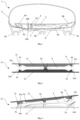
- In the following, the invention will be described in more detail with reference to the following figures:
- Fig. 1:
- illustrates an exemplary embodiment of the present invention;
- Fig. 2:
- illustrates an embodiment of a unit or component comprising an upper gliding element, a lower gliding element and a slider element arranged between the upper gliding element and the lower gliding element according to the present invention;
- Fig. 3:
- illustrates another embodiment of a unit or component comprising an upper gliding element, a lower gliding element and a slider element arranged between the upper gliding element and the lower gliding element according to the present invention;
- Figs. 4A and 4B:
- show a further embodiment of a unit or component comprising an upper gliding element, a lower gliding element and a slider element arranged between the upper gliding element and the lower gliding element according to the present invention;
- Fig. 5:
- illustrates another embodiment of a unit or component comprising an upper gliding element, a lower gliding element and a slider element arranged between the upper gliding element and the lower gliding element according to the present invention;
- Fig. 6:
- illustrates another embodiment of a unit or component comprising an upper gliding element, a lower gliding element and a slider element arranged between the upper gliding element and the lower gliding element according to the present invention; and
- Figs. 7A and 7B:
- show an embodiment of a sole structure according to the present invention.
- In the following only some possible embodiments of the invention are described in detail. However, the present invention is not limited to these, and a multitude of other embodiments are applicable without departing from the scope of the invention. The presented embodiments can be modified in a number of ways and combined with each other whenever compatible and certain features may be omitted in so far as they appear dispensable. In particular, the disclosed embodiments may be modified by combining certain features of one embodiment with one or more features of another embodiment.
- It is to be understood that not all features of the described aspects / embodiments have to be present for realizing the technical advantages provided by the present disclosure, which is defined by the subject-matter of the claims. The disclosed aspects / embodiments may be modified by combining certain features of one aspect / embodiment with one or more features of another aspect / embodiment. Specifically, the skilled person will understand that features, and / or functional elements of one aspect / embodiment can be combined with technically compatible features, and / or functional elements of any other aspect / embodiment of the present disclosure given that the resulting combination falls within the definition of the present disclosure.
- Throughout the present figures and specification, the same reference numerals refer to the same elements. For the sake of clarity and conciseness, certain aspects of components or steps of certain embodiments are presented without undue detail where such detail would be apparent to those skilled in the art in light of the teachings herein and / or where such detail would obfuscate an under-standing of more pertinent aspects of the embodiments.
- As understood by the skilled person and / or in order to avoid redundancies, reference is also made to the explanations in the preceding sections, which also apply to the following detailed description. Further, not all features, parts, elements, aspects, components and / or steps are expressly indicated by reference signs for the sake of brevity and clarity. This particularly applies, where the skilled person recognizes that such features, parts, elements, aspects, components and / or steps are present in a plurality.
- In the figures which are to be described in the following the medial side of the shoe, sole structure or elements/components is assumed to be on the left side of the respective figure, whereas the lateral side is assumed to be on the right side of the respective figure. The terms "lateral" and "medial" are defined based on the anatomy of the human foot. The medial side of the foot faces the midline of the body while the lateral side faces away from the midline of the body.
-
Fig. 1 illustrates an exemplary embodiment of the present invention by means of a cross section through a forefoot portion of ashoe 1 comprising asole structure 2 according to the invention and an upper 3. The shoe is a soccer shoe, but the invention may be applied to a wide variety of shoes, in particular sports shoes. Examples include basketball shoes, running shoes, tennis shoes, training shoes, etc. - The
sole structure 2 comprises a slider element having amedial portion 4a and alateral portion 4b. It is understood that theportions Fig. 1 . Henceforth, the slider element will be denoted with thereference numeral 4. - In the exemplary embodiment of
Fig. 1 , theslider element 4 rests on the upper 3 which wraps around the foot. The upper 3 may be provided with a low friction surface so that theslider element 2 can easily move in a transverse direction of thesole structure 2. A transverse direction is understood as a lateral-to-medial direction or a direction being essentially orthogonal to a longitudinal axis of thesole structure 2 or theshoe 1. As such, theslider element 4 is configured to slide in a direction indicated by thearrow 5 inFig. 1 . - The
sole structure 2 also comprises afoot support element 6 on which the foot rests. In other embodiments, thefoot support element 6 is covered by an insole, sockliner or the like, but this does not alter the basic principles of the invention. Thefoot support element 6 comprises amedial portion 6a and alateral portion 6b which are again defined with respect to the foot. Furthermore, the support element comprises twopressure elements foot support element 6. Themedial pressure element 7a is arranged on themedial portion 6a of thefoot support element 6, whereas thelateral pressure element 7b is arranged on thelateral portion 6b of thefoot support element 6. Themedial pressure element 7a is in contact with themedial portion 4a of theslider element 4, whereas thelateral pressure element 7b is in contact with thelateral pressure element 4b. - The
medial portion 4a and thelateral portion 4b of the slider element both comprise inclined gliding surfaces. The surfaces are inclined or tilted relative to a plane defined by thesole structure 2. In the example ofFig. 1 , such a plane would be perpendicular to the plane of projection, and the sliding trajectory of the slider element denoted by thereference numeral 5 would lie in this plane. Exemplary angles of inclination of the gliding surfaces shown in the embodiments described herein include 10°-45°, more preferably 10°-30° and most preferably around 20°. As will be described below, the angle of inclination of a gliding surface need not to be constant but can vary across the gliding surface. - Pressure exerted onto the
medial portion 6a of thefoot support element 6 by the foot, for example during a cut movement, is passed to the gliding surface of themedial portion 4a of theslider element 4 by means of thepressure element 7a. Due to the inclination of the gliding surface of themedial portion 4a of theslider element 4, theslider element 4 is caused to slide towards the lateral side of the sole structure or shoe. Consequently, the inclined gliding surface of thelateral portion 4b of the slider element pushes thelateral side 6b of thefoot support element 6 upwards by means of the pressure element. At the same time, themedial portion 6a of thefoot support element 6 is lowered as thepressure element 7a slides down the inclined surface of the medial portion of theslider element 4. In this way, the entire foot support element is tilted to the medial side of thesole structure 2 or shoe such that a pronounced banking effect is generated. Typical tilting angles achieved in the embodiments of the present invention range from 1 to 20 degrees. - If pressure is now applied to the lateral side of the
sole structure 2, for example because the wearer has finished a cut movement and shifts weights from the medial to the lateral side, thelateral pressure element 7b will interact with the inclined gliding surface of thelateral portion 4b of theglider element 4. The pressure or force exerted onto this inclined surface causes theglider element 4 to move towards the medial side of thesole structure 2 orshoe 1. Thelateral pressure element 7b slides down the inclined gliding surface of thelateral portion 4b of theglider element 4. At the same time, the inclined gliding surface of themedial portion 4a of theglider element 4 pushes thelateral pressure element 7a up. As a result, thefoot support element 6 tilts back towards the lateral side and into the neutral, horizontal position. - Generally, the inclination angle at the
medial portion 4a of the slider element needs to be as low as possible so that thefoot support element 6 does not abruptly start tilting but that instead there is a smooth transition from the neutral position to the banking position. Conversely, the inclination angle needs to be high enough so that a force or pressure transfer onto theslider element 4 activates the banking effect. - In the exemplary embodiment of
Fig. 1 , the inclined gliding surface of thelateral portion 4b of the glider element is concave. Therefore, when theglider element 4 starts sliding back towards the medial side of thesole structure 2, thelateral pressure element 7b is in contact with the steeper portion of the gliding surface such that the restoring force is large. In contrast, when theglider element 4 has almost reached the medial side, thelateral pressure element 7b is in contact with the flat-angle portion of the gliding surface and the restoring force is comparably small. This is also the reason, why theslider element 4 cannot be pushed further into the medial direction. Therefore, no banking effect to the lateral side can occur in the embodiment ofFig. 1 . - Assuming that
Fig. 1 shows a right shoe of a shoe of pairs, the left shoe would typically also allow a banking effect in just a medial direction (of the left foot). The banking effect is said to be symmetrical. In other embodiments, an asymmetrical banking effect with respect to a pair of shoes can be achieved by allowing a banking effect to the medial side in one shoe (e.g. the right shoe) and to the lateral side in the other shoe (e.g. the left shoe). With reference to a particular foot, the banking would be opposite (medial versus lateral) but from an absolute point of view the banking would be in the same direction (the left or right side of the wearer). Such an embodiment may be advantageous for example for track running where the direction of lateral acceleration is always the same. - The sole structure in the embodiment of
Fig. 1 also comprises aground facing element 8 which arranged beneath the portion of the upper 3 wrapping under the foot. In this exemplary embodiment, theground facing element 8 is configured to contact the ground but in other embodiments, the ground facing element may not directly contact the ground. For example, an outsole may be arranged beneath the ground facing element which is configured to contact the ground. In the exemplary embodiment ofFig. 1 , theground facing element 8 comprises a plurality of cleats, three of which are shown in the cross-section and denoted byreference numerals cleat 9b arranged in the middle fully overlaps with theslider element 4, whereas theouter cleats slider element 4 depending on the position of theslider element 4, i.e. whether it is in the neutral position on the medial side of thesole structure 2 orshoe 1 or the banking position on the lateral side of thesole structure 2 orshoe 1 as described above. - The
sole structure 2 also comprises apivot point 10 around which thefoot support element 6 rotates when moving from the neutral position to the banking position and vice-versa. Thepivot point 10 in the exemplary embodiment ofFig. 1 is realized by ascrew 10a. The head of the screw abuts the bottom surface of theground facing element 8. The shaft of thescrew 10a projects through theground facing element 8, the portion of the upper 3 wrapping under the foot and thefoot support element 6. It is held in place by a matchingnut 10b which is partly arranged in thefoot support element 6. Thus, thescrew 10a and thenut 10b secure thesole structure 2. As there is a small gap between thefoot support element 8 and thescrew 10a as well as thenut 10b, thefoot support element 8 can still rotate and tilt relative to theground facing element 8. In addition, thefoot support element 8 is flexible to some extent. - The
pivot point 10 is offset to the medial side of the sole structure. It does not lie on a longitudinal axis of thesole structure 2 and/orshoe 1. This allows to increase the maximum tilt or banking angle. Typical offsets in the context of the present invention may be 5 % to 40 %, preferably 10 % to 30 %, more preferably around 20% of the foot width. In relation to the width of thefoot support element 6 at the location of theslider element 4 the pivot point may be offset from a transversal center of the width of thefoot support element 6 towards the medial or lateral side at a distance from 5 to 35 % of the width of the foot support element, preferably 10 to 30 %, more preferably 15 to 25 %. - Generally, suitable materials for all the embodiments presented herein include nylon, polyoxymethylene (POM), polytetrafluoroethylene (PTFE), polyamide-imide (PAI), polyetherimide (PEI), polyether ether ketone (PEEK) and/or polyamide (PA), or other materials providing low friction and sufficient strength but also relatively low weight.
- Having described the principle underlying the present invention, additional embodiments will now be described.
-
Fig. 2 illustrates a unit orcomponent 11 comprising anupper gliding element 12 and alower gliding element 13 and aslider element 4 arranged between theupper gliding element 12 and thelower gliding element 13. The unit orcomponent 11 may be integrated in a sole structure according to the invention. Alternatively, theupper gliding element 12 and/or thelower gliding element 13 may be integrally formed with the rest of the sole structure. For example theupper gliding element 12 may be an integral part of a foot support element described previously and thelower gliding element 13 may be an integral part of a ground facing element described previously. - In the exemplary embodiment of
Fig. 2 theslider element 4 comprises four gliding surfaces, namely anupper gliding surface 14a and alower gliding surface 14b on themedial side 4a and anupper gliding surface 14c and alower gliding surface 14d on thelateral side 4b. - Matching the four gliding surfaces of the
slider element 4 are fourpressure elements pressure element 7a is arranged on the bottom side of theupper gliding element 12 and contacts the uppermedial gliding surface 14a of theglider element 4. Thepressure element 7b is arranged on the top side of thelower gliding element 13 and contacts the lowermedial gliding surface 14b of theglider element 4. Thepressure element 7c is arranged on the bottom side of theupper gliding element 12 and contacts the upperlateral gliding surface 14c of theglider element 4. Thepressure element 7d is arranged on the top side of thelower gliding element 13 and contacts the lowerlateral gliding surface 14d of theglider element 4. Just like the lateral gliding surface of the embodiment ofFig. 1 , all glidingsurfaces - The unit or
component 11 also comprises apivot point 10 around which theupper gliding element 12 and thelower gliding element 13 can rotate relative to each other to create a banking effect in a sole structure as described herein. Thepivot point 10 in this example is realized by two abutting barrel-shaped protrusions arranged on the upper 12 and lower 13 gliding elements, respectively. - The
slider element 4 as well as the upper 12 and lower 13 gliding elements in the example ofFig. 1 are symmetric. Hence, contrary to the embodiment ofFig. 1 , a banking effect will be achieved in both a lateral and a medial direction. More specifically, theslider element 4 when sliding in a lateral direction will cause theupper gliding element 12 to raise its lateral side and to lower its medial side compared to thelower gliding element 13. Conversely, when theslider element 4 slides in a medial direction, will cause theupper gliding element 12 to raise its medial side and to lower its lateral side relative to thelower gliding element 13. In the neutral position, which is shown inFig. 1 , theupper gliding element 12 and thelower gliding element 13 are parallel to each other and no banking effect occurs. - Just like in the embodiment of
Fig. 1 , the sliding of theslider element 4 is caused by pressure or force exerted on the medial or lateral portion of theupper gliding element 12. Thus, pressure or force exerted on the medial portion of theupper gliding element 12 will cause theslider element 4 to slide towards the lateral side and pressure exerted on the lateral side of theupper gliding element 12 will cause theslider element 4 to slide towards the medial side. This is achieved by the interaction of thepressure elements gliding surfaces -
Fig. 3 illustrates a unit orcomponent 11 comprising anupper gliding element 12 and alower gliding element 13 and aslider element 4 arranged between theupper gliding element 12 and thelower gliding element 13. The embodiment ofFig. 3 is similar to the embodiment ofFig. 2 . Also in this example, the unit orcomponent 11 is symmetric such that a banking effect in both medial and a lateral direction is achieved. Theslider element 4 comprises fourgliding surfaces corresponding pressure elements gliding elements 12, respectively. - In
Fig. 3 the unit orcomponent 11 is shown in a tilted position in which a banking effect occurs to the medial side. Just like in the embodiment ofFig.2 , the embodiment ofFig. 3 may also tilt to the lateral side due to its symmetric nature. -
Figures 4A and 4B show a further embodiment of a unit orcomponent 11 comprising anupper gliding element 12 and alower gliding element 13 and aslider element 4 arranged between theupper gliding element 12 and thelower gliding element 13.Fig. 4A shows the unit orcomponent 11 in a neutral position, whereasFig. 4B shows the unit orcomponent 11 in a tilted position. This embodiment is similar to the embodiments offigures 2 and 3 . However, instead of pressure elements, the upper 12 and lower 13 guiding elements comprise glidingsurfaces corresponding gliding surfaces slider element 4. As such thegilding surfaces - The embodiment of
figures 4A and 4B also comprises apivot point 10 which is realized as an upper pivot element connected to a lower pivot element, thereby connecting the upper 12 and lower 13 gliding elements. Theslider element 4 comprises anaperture 16 in which the rod is movably arranged. Thus, the upper/lower pivot elements and theaperture 16 limit the movements of theslider element 4 and form a guiding means for thesupport element 4. As an alternative to an upper and lower pivot element, a screw and a nut may be used as present in other embodiments described herein. Still another alternative would be to form the upper and lower gliding elements including its pivot point integrally. -
Fig. 5 illustrates another embodiment of a unit orcomponent 11 comprising anupper gliding element 12 and alower gliding element 13 and aslider element 4 arranged between theupper gliding element 12 and thelower gliding element 13. The embodiment is similar to the previous embodiments such that the description of the previous figures is applicable toFig. 5 as well. - The embodiment of
Fig. 5 comprises guidingportions portions element 12, thelower guiding element 13 and theslider element 4 from rotating relative to each other. InFig. 5 , guidingportion 16a is located on the anterior medial side of the upper guidingelement 12, guidingportion 16b is located on the anterior medial side of thelower guiding element 13, guidingportion 16c is located on the anterior lateral side of the upper guidingelement 12 and guidingportion 16d is located on the anterior medial side of thelower guiding element 13. There are similar guiding portions on the posterior sides of the upper 12 and lower 13 guiding element which are not shown inFig. 5 . Similar to the embodiment ofFig. 1 , thepivot point 10 of the embodiment ofFig. 5 is realized by ascrew 10a andnut 10b. -
Fig. 6 illustrates another embodiment of a unit orcomponent 11 comprising anupper gliding element 12 and alower gliding element 13 and aslider element 4 arranged between theupper gliding element 12 and thelower gliding element 13. The embodiment is similar to the previous embodiments such that the description of the previous figures is applicable toFig. 6 as well. In contrast to the embodiments offigures 2, 3 ,4A, 4B and 5 , the embodiment ofFig. 6 is not symmetric. Themedial portion 4a of theslider element 4 has a lower height than thelateral portion 4b of theslider element 4. Also, themedial pressure elements medial pressure elements lateral portion 4b of theslider element 4 are concave, whereas the upper and lower gliding surfaces of themedial portion 4a of theslider element 4 are flat, similar to the embodiment ofFig. 1 . - In the neutral position of the
slider element 4, thelateral pressure elements slider element 4. Therefore, when pressure or a force is exerted on the lateral portion of theupper gliding element 12, there will be no horizontal force component pushing theslider element 4 towards the medial side. In contrast, when pressure or a force is exerted on the medial side of theupper gliding element 12, thepressure elements medial portion 4a of the slider element. Therefore, there will be a horizontal force component pushing theslider element 4 towards the lateral side and lifting theupper gliding element 12 on its lateral side. Hence, in this embodiment, banking is only possible to the medial side but not the lateral side. - Once the
slider element 4 has moved to the lateral side of the unit orcomponent 11, thepressure elements slider element 4 having the largest inclination angle. Hence, a force or pressure exerted onto the lateral portion of theupper gliding element 12 will now cause a horizontal force component which will push theslider element 4 towards the medial side and restore it to the neutral position. Due to the large inclination angle of the gliding surfaces 14ca and 14d in the tilted position of theupper gliding element 12, the initial restoring force will be quite large. - Also, the
foot support element 6 is elastic. This allows theslider element 4 to elastically deform thefoot support element 6 when sliding. The side of thefoot support element 6 on which pressure is exerted (the "driven side") does not lower as much as the opposing side (the "reaction side") is lifted by theslider element 4. In this exemplary embodiment this is achieved by configuring the gliding surfaces 14a and 14b with a smaller angle compared to the opposing gliding surfaces 14c and 14d. When pressure is exerted on the medial side (the driven side) of theupper gliding element 12, theslider element 4 moves towards the lateral side (the reaction side). Because the opposing gliding surfaces 14c and 14d have a steeper angle than the medial gliding surfaces 14a and 14b, the lateral side of theupper gliding element 12 is actively lifted and bends upwards due to its elasticity. Thus, the lateral side of theupper gliding element 12 is lifted more than would be geometrically possible by a simple seesaw mechanism. -
Figures 7A and 7B show an embodiment of asole structure 2 according to the present invention in a bottom view (Fig. 7A ) and a top view (Fig. 7B ). The sole structure comprises anupper gliding element 12 and alower gliding element 13, and aslider element 4 arranged between theupper gliding element 12 and thelower gliding element 13 similar to the embodiments shown infigures 2, 3 ,4A, 4B ,5 and6 . In the embodiment offigures 7A and 7B , theupper gliding element 12 is integral with thefoot support element 6 and thelower gliding element 13 is integral with thefoot support element 8. However, in other embodiments, theupper gliding element 6,lower gliding element 8 and theslider element 4 could form a unit orcomponent 11 as previously described (for example with respect tofigures 4A and 4B ), which could be sandwiched between thefoot support element 6 and theground facing element 8. - The bottom side of the
sole structure 2 comprises theground facing element 8 comprising a number of cleats, three of which are exemplarily denoted byreference numerals slider element 4 is arranged above the threecleats medial cleat 9a via themiddle cleat 9b to thelateral cleat 9c (seeFig. 7A ). - The upper side of the
sole structure 2 comprises the foot support element 6 (seeFig. 7B ). Thefoot support element 6 in this example covers a portion of the sole and extends from the metatarsal bones to the middle of the arch. In other embodiments, the foot support element may cover the entire length of the foot or a different portion. Also, thefoot support element 6 does not cover the entire width of thesole structure 2. As shown inFig. 7B , theground facing element 8 extends beyond thefoot support element 6. Thus, thefoot support element 6 is received in theground facing element 8 is free to tilt to achieve a banking effect as described herein. - In
Fig. 7B the location of theslider element 4 arranged between theupper gliding element 12 and thelower gliding element 13 is marked by therectangle 17. Thefoot support element 6 and theground facing element 8 are secured by ascrew 10a (seeFig. 7A ) which extends through theslider element 4 and into acorresponding nut 10b (seeFig. 7B ). - Generally, in all embodiments, the width of the
slider element 4 should be as large as possible to sufficiently support the foot, without having too much overhanging portions of thefoot support element 6 in the lateral and medial direction. On the other hand, the width of the slider element must be small enough, so that the slider can still move. Therefore, a preferred width of the slider element is a minimum of 60% of the maximum width of the upper at the metatarsal joints and a maximum of 90%. - Generally, in all embodiments the height of the sole structure including the
slider element 4 should be as small as possible to avoid a high sole. In some embodiments, thefoot support element 6 would extend across the entire length of a sole of a foot. In other embodiments, just a portion of the sole of the foot is covered by thefoot support element 6. In still other embodiments, the sole structure would comprise multiple slider elements and corresponding gliding surfaces as described herein. Those slider elements may be arranged along the length of the sole structure, for example between a foot support plate and a cleated plate. In one embodiment, the sole structure comprises a first slider element in a metatarsal region and a second slider element in a heel region. In another embodiment, the sole structure comprises a first slider element and at least one further slider element in a forefoot region, to sufficiently support a foot support element extending in the forefoot region. In yet another embodiment, the sole structure comprises at least one slider element in the midfoot region. - The length, i.e. the dimension of a
single slider element 4 in a longitudinal direction is limited to maintain the sliding function. The length of a single slider element may be preferably at maximum 15 % of the entire length of the shoe. Theslider element 4 may generally be arranged in a rotated position relative to a transversal axis of the sole structure or the shoe. Thus, banking is enabled not just in a purely transversal direction but in an intermediate direction between a purely longitudinal and a purely transversal direction. In an extreme embodiment, the slider element may be rotated up to 90 degrees to the transversal axis of the sole structure or shoe so that it lies substantially along a longitudinal axis of the shoe. This would enable banking in a longitudinal direction. - In the embodiments described the
slider element 4 is restored to its neutral position by a force or pressure acting on either the medial or lateral portion of thesole structure 2. In those embodiments, the restoring force is generated by at least one inclined surface which splits the force or pressure acting on the sole structure into a vertical and horizontal component. The horizontal force component pushes theslider element 4 back to its original position. However, in other embodiments not shown in the figures, the restoring force may be provided by a spring element which either pushes or pulls theslider element 4 back to its neutral position. In those embodiments a single inclined gliding surface would be sufficient to create a banking effect. - A sole structure according to this embodiment comprises a slider element configured to slide in a transverse direction of the sole structure, wherein the slider element is configured to slide towards a first side of the sole structure when pressure is applied to an edge portion of the sole structure, and a spring element configured to push or pull the slider element to a second side of the sole structure opposite the first side. This embodiment can have one or more of the features of the embodiments described previously. In other words, it can be combined with the previous embodiments or subcombinations of their features. However, contrary to those embodiments, it is not necessary to apply a pressure or force to the opposing side of the sole structure to restore the slider element to its original position. Rather, this is accomplished by the spring element.
- In the following, further embodiments are described to facilitate understanding the invention:
- 1. Sole structure (2) for a shoe (1), wherein the sole structure (2) comprises:
- a slider element (4) configured to slide in a transverse direction of the sole structure,
- wherein the slider element (4) is configured to slide towards a medial side of the sole structure (2) when pressure is applied to a lateral portion of the sole structure (2) and,
- wherein the slider element (4) is configured to slide towards a lateral side of the sole structure (2) when pressure is applied to a medial portion of the sole structure (2).
- 2. Sole structure (2) of
embodiment 1, wherein the sole structure (2) is configured such that a thickness of the medial portion of the sole structure (2) increases when the slider element (4) slides towards the medial side of the sole structure (2) and, wherein the sole structure (2) is configured such that a thickness of the lateral portion of the sole structure (2) increases when the slider element (4) slides towards the lateral side of the sole structure (2). - 3. Sole structure (2) of one of embodiments 1-2, wherein the sliding of the slider element (4) causes a top surface of the sole structure (2) to tilt with respect to a lower surface of the sole structure (2).
- 4. Sole structure (2) of one of embodiments 1-3 further comprising a foot support element (6) configured to interact with the slider element (4), such that the slider element (4) slides towards the medial side of the sole structure (2) when pressure is applied to a lateral portion of the foot support element (6) and such that the slider element (2) slides towards the lateral side of the sole structure (2) when pressure is applied to a medial portion of the foot support element (6).
- 5. Sole structure (2) of one of embodiments 1-4, further comprising:
- at least one gliding surface (14a, 14b, 14c, 14d) which is tilted relative to a horizontal plane defined by the sole structure (2); and
- at least one pressure element (7a, 7b, 7c, 7d) which is configured to interact with the gliding surface (14a, 14b, 14c, 14d) such that the slider element (4) is caused to slide when pressure is applied to the sole structure (2).
- 6. Sole structure (2) of
embodiment 5, wherein at least one end of the slider element (2) comprises a gliding surface (14a, 14b, 14c, 14d) or a pressure element. - 7. Sole structure (2) of one of embodiments 4-6, further comprising a ground facing element (8), wherein the slider element (4) is sandwiched between the ground facing element (8) and the foot support element (6).
- 8. Sole structure (2) of embodiment 7, wherein at least portions of the lateral and/or medial edges of the ground facing element (8) and the foot support element (6) are unconnected and movable relative to each other.
- 9. Sole structure (2) of one of embodiments 7-8, wherein the ground facing element (8) and/or the foot support element (6) comprises a gliding surface (15a, 15b, 15c, 15d).
- 10. Sole structure (2) of one of embodiments 1-9, wherein the slider element (4) is arranged in a forefoot portion of the sole structure (2), preferably corresponding to metatarsal fat pads.
- 11. Sole structure (2) of one of embodiments 7-10, wherein the ground facing element (8) comprises at least one cleat (9a, 9b, 9c).
- 12. Sole structure (2) of
embodiment 11, wherein the slider element (4) is arranged in an overlapping manner with the at least one cleat (9a, 9b, 9c). - 13. Sole structure (2) of one of embodiments 1-12, further comprising an upper gliding element (12) and/or a lower gliding element (13), wherein the upper gliding element (12) and the lower gliding element (13) are configured to interact with the slider element (4).
- 14. Sole structure (2) of
embodiment 13, wherein the upper gliding element (12) and/or the lower gliding element (13) comprise at least one gliding surface (15a, 15b, 15c, 15d) which is tilted relative to a horizontal plane defined by the sole structure (2) and configured to interact with a gliding surface (14a, 14b, 14c, 14d) or a pressure element of the slider element (4) such that the slider element (4) is caused to slide when pressure is applied to the sole structure (2). - 15. Sole structure (2) of one of embodiments 13-14, wherein the upper gliding element (12) and/or the lower gliding (13) element comprise at least one pressure element (7a, 7b, 7c, 7d) which is configured to interact with a gliding surface (14a, 14b, 14c, 14d) of the slider element (4) such that the slider element (4) is caused to slide when pressure is applied to the sole structure (2).
- 16. Sole structure (2) of one of embodiments 13-15, further comprising a pivot point (10), wherein the upper gliding element (12) is connected to the lower gliding element (13) at the pivot point (10).
- 17. Sole structure (2) of
embodiment 16, wherein the pivot point (10) is realized by a screw (10a) and a nut (10b). - 18. Sole structure (2) of one of embodiments 16-17, wherein the pivot point (10) is located more proximal to a medial side of the sole structure (2) than to a lateral side.
- 19. Sole structure (2) of one of embodiments 16-18, wherein the slider element (4) comprises an aperture (16) and, wherein the pivot point (10) is arranged at least partially in the aperture (16).
- 20. Sole structure (2) of one of embodiments 3-19, wherein the tilting of the top surface of the sole structure (2) with respect to a lower surface of the sole structure (2) defines a tilting angle, wherein a maximum tilting angle is 5 degrees or more and preferably at most 10 degrees.
- 21. Sole structure (2) of one of embodiments 3-20, wherein the sole structure (2) is configured such that a tilting in only one of a medial direction and a lateral direction is possible, preferably only in the medial direction.
- 22. Sole structure (2) of one of embodiments 6-21, wherein a first end (4a) of the slider element (4) comprises a first gliding surface (14a, 14b) and a second end (4b) of the slider element (14c, 14d) comprises a second gliding surface (14c, 14d), wherein the first gliding surface (14a, 14b) is essentially flat and, wherein the second gliding surface (14c, 14d) comprises a concave shape.
- 23. Sole structure (2) of one of embodiments 1-22, wherein the slider element (2) comprises nylon, polyoxymethylene, POM, polytetrafluoroethylene, PTFE, polyamide-imide, PAI, polyetherimide, PEI, polyether ether ketone, PEEK, and/or polyamide, PA.
- 24. Shoe (1) comprising:
- a sole structure (2) of one of embodiments 1-23; and
- an upper (3) coupled to the sole structure (2).
- 25. Shoe (1) of embodiment 24, wherein the upper (3) is coupled to either the foot support element (6) or the ground facing element (8).
- 26. Shoe (1) of embodiment 24, wherein the upper (3) is coupled to the sole structure (2) such that the top surface of the sole structure (2) is able to tilt with respect to the lower surface of the sole structure (2).
Claims (15)
- Sole structure (2) for a shoe (1), wherein the sole structure (2) comprises:
a slider element (4) configured to slide in a transverse direction of the sole structure,wherein the slider element (4) is configured to slide towards a medial side of the sole structure (2) when pressure is applied to a lateral portion of the sole structure (2) and,wherein the slider element (4) is configured to slide towards a lateral side of the sole structure (2) when pressure is applied to a medial portion of the sole structure (2). - Sole structure (2) of claim 1, wherein the sole structure (2) is configured such that a thickness of the medial portion of the sole structure (2) increases when the slider element (4) slides towards the medial side of the sole structure (2) and, wherein the sole structure (2) is configured such that a thickness of the lateral portion of the sole structure (2) increases when the slider element (4) slides towards the lateral side of the sole structure (2).
- Sole structure (2) of one of claims 1-2, wherein the sliding of the slider element (4) causes a top surface of the sole structure (2) to tilt with respect to a lower surface of the sole structure (2).
- Sole structure (2) of one of claims 1-3 further comprising a foot support element (6) configured to interact with the slider element (4), such that the slider element (4) slides towards the medial side of the sole structure (2) when pressure is applied to a lateral portion of the foot support element (6) and such that the slider element (2) slides towards the lateral side of the sole structure (2) when pressure is applied to a medial portion of the foot support element (6).
- Sole structure (2) of one of claims 1-4, further comprising:at least one gliding surface (14a, 14b, 14c, 14d) which is tilted relative to a horizontal plane defined by the sole structure (2); andat least one pressure element (7a, 7b, 7c, 7d) which is configured to interact with the gliding surface (14a, 14b, 14c, 14d) such that the slider element (4) is caused to slide when pressure is applied to the sole structure (2), preferably wherein at least one end of the slider element (2) comprises a gliding surface (14a, 14b, 14c, 14d) or a pressure element.
- Sole structure (2) of one of claims 4-5, further comprising a ground facing element (8), wherein the slider element (4) is sandwiched between the ground facing element (8) and the foot support element (6), preferably wherein at least portions of the lateral and/or medial edges of the ground facing element (8) and the foot support element (6) are unconnected and movable relative to each other, further preferably wherein the ground facing element (8) and/or the foot support element (6) comprises a gliding surface (15a, 15b, 15c, 15d).
- Sole structure (2) of one of claims 1-6, wherein the slider element (4) is arranged in a forefoot portion of the sole structure (2), preferably corresponding to metatarsal fat pads.
- Sole structure (2) of one of claims 6-7, wherein the ground facing element (8) comprises at least one cleat (9a, 9b, 9c) preferably wherein the slider element (4) is arranged in an overlapping manner with the at least one cleat (9a, 9b, 9c).
- Sole structure (2) of one of claims 1-8, further comprising an upper gliding element (12) and/or a lower gliding element (13), wherein the upper gliding element (12) and the lower gliding element (13) are configured to interact with the slider element (4), preferably wherein the upper gliding element (12) and/or the lower gliding element (13) comprise at least one gliding surface (15a, 15b, 15c, 15d) which is tilted relative to a horizontal plane defined by the sole structure (2) and configured to interact with a gliding surface (14a, 14b, 14c, 14d) or a pressure element of the slider element (4) such that the slider element (4) is caused to slide when pressure is applied to the sole structure (2).
- Sole structure (2) of claim 9, wherein the upper gliding element (12) and/or the lower gliding (13) element comprise at least one pressure element (7a, 7b, 7c, 7d) which is configured to interact with a gliding surface (14a, 14b, 14c, 14d) of the slider element (4) such that the slider element (4) is caused to slide when pressure is applied to the sole structure (2).
- Sole structure (2) of one of claims 9-10, further comprising a pivot point (10), wherein the upper gliding element (12) is connected to the lower gliding element (13) at the pivot point (10), preferably wherein the pivot point (10) is realized by a screw (10a) and a nut (10b) further preferably wherein the pivot point (10) is located more proximal to a medial side of the sole structure (2) than to a lateral side, further preferably wherein the slider element (4) comprises an aperture (16) and, wherein the pivot point (10) is arranged at least partially in the aperture (16).
- Sole structure (2) of one of claims 3-11, wherein the tilting of the top surface of the sole structure (2) with respect to a lower surface of the sole structure (2) defines a tilting angle, wherein a maximum tilting angle is 5 degrees or more and preferably at most 10 degrees, preferably wherein the sole structure (2) is configured such that a tilting in only one of a medial direction and a lateral direction is possible, preferably only in the medial direction.
- Sole structure (2) of one of claims 5-12, wherein a first end (4a) of the slider element (4) comprises a first gliding surface (14a, 14b) and a second end (4b) of the slider element (14c, 14d) comprises a second gliding surface (14c, 14d), wherein the first gliding surface (14a, 14b) is essentially flat and, wherein the second gliding surface (14c, 14d) comprises a concave shape.
- Sole structure (2) of one of claims 1-13, wherein the slider element (2) comprises nylon, polyoxymethylene, POM, polytetrafluoroethylene, PTFE, polyamide-imide, PAI, polyetherimide, PEI, polyether ether ketone, PEEK, and/or polyamide, PA.
- Shoe (1) comprising:a sole structure (2) of one of claims 1-14; andan upper (3) coupled to the sole structure (2), preferably wherein the upper (3) is coupled to either the foot support element (6) or the ground facing element (8), or wherein the upper (3) is coupled to the sole structure (2) such that the top surface of the sole structure (2) is able to tilt with respect to the lower surface of the sole structure (2).
Applications Claiming Priority (1)
| Application Number | Priority Date | Filing Date | Title |
|---|---|---|---|
| DE102023136525.8A DE102023136525B4 (en) | 2023-12-22 | 2023-12-22 | Sole structure with banking effect |
Publications (1)
| Publication Number | Publication Date |
|---|---|
| EP4573949A1 true EP4573949A1 (en) | 2025-06-25 |
Family
ID=93923324
Family Applications (1)
| Application Number | Title | Priority Date | Filing Date |
|---|---|---|---|
| EP24219344.9A Pending EP4573949A1 (en) | 2023-12-22 | 2024-12-12 | Sole structure with banking effect |
Country Status (3)
| Country | Link |
|---|---|
| US (1) | US20250204638A1 (en) |
| EP (1) | EP4573949A1 (en) |
| DE (1) | DE102023136525B4 (en) |
Families Citing this family (2)
| Publication number | Priority date | Publication date | Assignee | Title |
|---|---|---|---|---|
| US20260033592A1 (en) * | 2024-08-05 | 2026-02-05 | Nike, Inc. | Athletic systems |
| US12593893B2 (en) | 2024-08-05 | 2026-04-07 | Nike, Inc. | Athletic systems |
Citations (11)
| Publication number | Priority date | Publication date | Assignee | Title |
|---|---|---|---|---|
| US5224810A (en) * | 1991-06-13 | 1993-07-06 | Pitkin Mark R | Athletic shoe |
| DE10244433A1 (en) | 2002-09-24 | 2004-04-01 | Adidas International Marketing B.V. | Sliding element and shoe sole |
| DE10244435A1 (en) | 2002-09-24 | 2004-04-01 | Adidas International Marketing B.V. | Sliding element and shoe sole |
| JP2005224335A (en) | 2004-02-12 | 2005-08-25 | Keiai Orthopedic Appliance Co Ltd | Shoe for correction |
| DE102013202353A1 (en) | 2013-02-13 | 2014-08-14 | Adidas Ag | Sole for a shoe |
| DE102013202306A1 (en) | 2013-02-13 | 2014-08-14 | Adidas Ag | Sole for a shoe |
| US20160007684A1 (en) * | 2011-02-04 | 2016-01-14 | Nike, Inc. | Article of Footwear with Decoupled Upper |
| US9756904B2 (en) | 2015-02-10 | 2017-09-12 | Nike, Inc. | Track-and-field athletic shoes with auto bankable spikes |
| US9833038B2 (en) * | 2015-03-19 | 2017-12-05 | Nike, Inc. | Multi-density midsole and plate system |
| EP4176753A1 (en) | 2021-11-05 | 2023-05-10 | Puma Se | Sole structure for article of footwear |
| EP4268659A1 (en) | 2022-04-29 | 2023-11-01 | adidas AG | Outsole for a shoe |
Family Cites Families (19)
| Publication number | Priority date | Publication date | Assignee | Title |
|---|---|---|---|---|
| US1690837A (en) * | 1926-02-23 | 1928-11-06 | Rehle Ignaz | Insertable arch support |
| US1998921A (en) * | 1934-05-09 | 1935-04-23 | John C Brown | Attachment for shoes |
| US3782011A (en) * | 1972-10-05 | 1974-01-01 | R Fisher | Safety sole for sport shoe |
| US3951407A (en) * | 1975-04-14 | 1976-04-20 | Calacurcio Frank C | Device for use on a golf shoe |
| US4037847A (en) * | 1976-02-06 | 1977-07-26 | Lorang Walter R | Golf swing training apparatus |
| US4342158A (en) * | 1980-06-19 | 1982-08-03 | Mcmahon Thomas A | Biomechanically tuned shoe construction |
| US4407079A (en) * | 1981-06-04 | 1983-10-04 | Chiroff Lee M | Golf aid device |
| US5377431A (en) * | 1993-06-15 | 1995-01-03 | Walker; Andrew S. | Directionally yieldable cleat assembly |
| US5881478A (en) * | 1998-01-12 | 1999-03-16 | Converse Inc. | Midsole construction having a rockable member |
| US6948262B2 (en) * | 2001-04-03 | 2005-09-27 | Kerrigan D Casey | Cantilevered shoe construction |
| CA2503523C (en) * | 2002-10-26 | 2010-10-19 | Andrea Drollinger | Sports shoe |
| US8151485B2 (en) * | 2008-01-11 | 2012-04-10 | Nike, Inc. | Article of footwear with forefoot plates |
| US8387277B2 (en) * | 2008-06-23 | 2013-03-05 | Board Of Trustees Of The Leland Stanford Junior University | Therapeutic system and method for altering the gait of a patient |
| US7654014B1 (en) * | 2008-12-08 | 2010-02-02 | Brian L. Moore | Golf shoe |
| US9155356B2 (en) * | 2012-02-27 | 2015-10-13 | Puma SE | Shoe sole, shoe with such a shoe sole and method for the production of such a shoe sole |
| US11445784B2 (en) * | 2012-04-12 | 2022-09-20 | Worcester Polytechnic Institute | Adjustable response elastic kinetic energy converter and storage field system for a footwear appliance |
| US10111492B2 (en) * | 2014-08-26 | 2018-10-30 | Nike, Inc. | Article of footwear with dynamic edge cavity midsole |
| US9924763B2 (en) * | 2015-08-17 | 2018-03-27 | Nike, Inc. | Article of footwear including sole component providing lateral roll control structure |
| US11752413B2 (en) * | 2016-12-31 | 2023-09-12 | Under Armour, Inc. | Article of footwear with multiple durometer outsole and directional cleat pattern |
-
2023
- 2023-12-22 DE DE102023136525.8A patent/DE102023136525B4/en active Active
-
2024
- 2024-12-12 EP EP24219344.9A patent/EP4573949A1/en active Pending
- 2024-12-19 US US18/988,108 patent/US20250204638A1/en active Pending
Patent Citations (12)
| Publication number | Priority date | Publication date | Assignee | Title |
|---|---|---|---|---|
| US5224810A (en) * | 1991-06-13 | 1993-07-06 | Pitkin Mark R | Athletic shoe |
| DE10244433A1 (en) | 2002-09-24 | 2004-04-01 | Adidas International Marketing B.V. | Sliding element and shoe sole |
| DE10244435A1 (en) | 2002-09-24 | 2004-04-01 | Adidas International Marketing B.V. | Sliding element and shoe sole |
| JP2005224335A (en) | 2004-02-12 | 2005-08-25 | Keiai Orthopedic Appliance Co Ltd | Shoe for correction |
| US20160007684A1 (en) * | 2011-02-04 | 2016-01-14 | Nike, Inc. | Article of Footwear with Decoupled Upper |
| DE102013202353A1 (en) | 2013-02-13 | 2014-08-14 | Adidas Ag | Sole for a shoe |
| DE102013202306A1 (en) | 2013-02-13 | 2014-08-14 | Adidas Ag | Sole for a shoe |
| US9756904B2 (en) | 2015-02-10 | 2017-09-12 | Nike, Inc. | Track-and-field athletic shoes with auto bankable spikes |
| US9833038B2 (en) * | 2015-03-19 | 2017-12-05 | Nike, Inc. | Multi-density midsole and plate system |
| EP4176753A1 (en) | 2021-11-05 | 2023-05-10 | Puma Se | Sole structure for article of footwear |
| US20230142549A1 (en) * | 2021-11-05 | 2023-05-11 | Puma SE | Sole structure for article of footwear |
| EP4268659A1 (en) | 2022-04-29 | 2023-11-01 | adidas AG | Outsole for a shoe |
Also Published As
| Publication number | Publication date |
|---|---|
| US20250204638A1 (en) | 2025-06-26 |
| DE102023136525A1 (en) | 2025-06-26 |
| DE102023136525B4 (en) | 2026-02-12 |
Similar Documents
| Publication | Publication Date | Title |
|---|---|---|
| US11154116B2 (en) | Sole structure with segmented portions | |
| US9936765B2 (en) | Sole structure for a shoe | |
| US9661896B2 (en) | Shoe with elastically flexible extension | |
| US20250204638A1 (en) | Sole structure with banking effect | |
| US10182611B2 (en) | Article of footwear with flexible reinforcing plate | |
| US7913422B1 (en) | Pivoted energy-return shoe system | |
| CN101489429B (en) | Impact-attenuating members and products comprising such members | |
| US7905033B1 (en) | Energy-return shoe system | |
| US7950166B1 (en) | Simplified energy-return shoe system | |
| JP3990308B2 (en) | Shoe sole | |
| EP2132999A1 (en) | Shoe sole element | |
| US11969057B2 (en) | Sole for footwear with positioning faces | |
| US20260033589A1 (en) | Midsole for a sports shoe with banking effect | |
| CN115768299B (en) | Foot support system including tiltable forefoot components | |
| US20220061453A1 (en) | Apparatus and related methods of increasing foot propulsion | |
| US20260137163A1 (en) | Apparatus and related methods of increasing foot propulsion |
Legal Events
| Date | Code | Title | Description |
|---|---|---|---|
| PUAI | Public reference made under article 153(3) epc to a published international application that has entered the european phase |
Free format text: ORIGINAL CODE: 0009012 |
|
| STAA | Information on the status of an ep patent application or granted ep patent |
Free format text: STATUS: REQUEST FOR EXAMINATION WAS MADE |
|
| 17P | Request for examination filed |
Effective date: 20241212 |
|
| AK | Designated contracting states |
Kind code of ref document: A1 Designated state(s): AL AT BE BG CH CY CZ DE DK EE ES FI FR GB GR HR HU IE IS IT LI LT LU LV MC ME MK MT NL NO PL PT RO RS SE SI SK SM TR |
|
| GRAP | Despatch of communication of intention to grant a patent |
Free format text: ORIGINAL CODE: EPIDOSNIGR1 |
|
| STAA | Information on the status of an ep patent application or granted ep patent |
Free format text: STATUS: GRANT OF PATENT IS INTENDED |
|
| RIC1 | Information provided on ipc code assigned before grant |
Ipc: A43B 3/24 20060101AFI20251219BHEP Ipc: A43B 13/12 20060101ALI20251219BHEP Ipc: A43B 13/14 20060101ALI20251219BHEP Ipc: A43B 13/18 20060101ALI20251219BHEP |
|
| INTG | Intention to grant announced |
Effective date: 20260114 |
|
| GRAS | Grant fee paid |
Free format text: ORIGINAL CODE: EPIDOSNIGR3 |
|
| GRAA | (expected) grant |
Free format text: ORIGINAL CODE: 0009210 |
|
| STAA | Information on the status of an ep patent application or granted ep patent |
Free format text: STATUS: THE PATENT HAS BEEN GRANTED |