EP4572474A1 - Link configuration method and apparatus, and remote user equipment, network device and storage medium - Google Patents
Link configuration method and apparatus, and remote user equipment, network device and storage medium Download PDFInfo
- Publication number
- EP4572474A1 EP4572474A1 EP23862502.4A EP23862502A EP4572474A1 EP 4572474 A1 EP4572474 A1 EP 4572474A1 EP 23862502 A EP23862502 A EP 23862502A EP 4572474 A1 EP4572474 A1 EP 4572474A1
- Authority
- EP
- European Patent Office
- Prior art keywords
- link
- remote
- srb
- network device
- indirect
- Prior art date
- Legal status (The legal status is an assumption and is not a legal conclusion. Google has not performed a legal analysis and makes no representation as to the accuracy of the status listed.)
- Pending
Links
Images



Classifications
-
- H—ELECTRICITY
- H04—ELECTRIC COMMUNICATION TECHNIQUE
- H04W—WIRELESS COMMUNICATION NETWORKS
- H04W76/00—Connection management
- H04W76/10—Connection setup
-
- H—ELECTRICITY
- H04—ELECTRIC COMMUNICATION TECHNIQUE
- H04W—WIRELESS COMMUNICATION NETWORKS
- H04W76/00—Connection management
- H04W76/10—Connection setup
- H04W76/14—Direct-mode setup
-
- H—ELECTRICITY
- H04—ELECTRIC COMMUNICATION TECHNIQUE
- H04W—WIRELESS COMMUNICATION NETWORKS
- H04W76/00—Connection management
- H04W76/10—Connection setup
- H04W76/15—Setup of multiple wireless link connections
-
- H—ELECTRICITY
- H04—ELECTRIC COMMUNICATION TECHNIQUE
- H04W—WIRELESS COMMUNICATION NETWORKS
- H04W76/00—Connection management
- H04W76/10—Connection setup
- H04W76/18—Management of setup rejection or failure
-
- H—ELECTRICITY
- H04—ELECTRIC COMMUNICATION TECHNIQUE
- H04W—WIRELESS COMMUNICATION NETWORKS
- H04W76/00—Connection management
- H04W76/20—Manipulation of established connections
- H04W76/23—Manipulation of direct-mode connections
-
- H—ELECTRICITY
- H04—ELECTRIC COMMUNICATION TECHNIQUE
- H04W—WIRELESS COMMUNICATION NETWORKS
- H04W88/00—Devices specially adapted for wireless communication networks, e.g. terminals, base stations or access point devices
- H04W88/02—Terminal devices
- H04W88/04—Terminal devices adapted for relaying to or from another terminal or user
-
- H—ELECTRICITY
- H04—ELECTRIC COMMUNICATION TECHNIQUE
- H04W—WIRELESS COMMUNICATION NETWORKS
- H04W92/00—Interfaces specially adapted for wireless communication networks
- H04W92/16—Interfaces between hierarchically similar devices
- H04W92/18—Interfaces between hierarchically similar devices between terminal devices
Definitions
- the present disclosure relates to the field of communication technologies, and in particular, to a link configuration method, apparatus, remote UE, network device and storage medium.
- a remote User Equipment can access a network device through both a relay UE and a New Radio (NR) direct link, but there is an issue of insufficient network robustness.
- UE User Equipment
- NR New Radio
- embodiments of the present disclosure provide a link configuration method, apparatus, remote UE, network device, and storage medium.
- One embodiment of the present disclosure provides a link configuration method, applied to a network device, the method including: configuring a first Signaling Radio Bearer (SRB) and/or a second SRB on a first link to a remote user equipment (UE); wherein the first link represents a New Radio (NR) direct link or an indirect link.
- SRB Signaling Radio Bearer
- UE remote user equipment
- NR New Radio
- the configuring the first SRB and/or the second SRB on the first link to the remote UE includes: adding and activating a split SRB 1, and/or adding and activating a split SRB2, on the NR direct link to the remote UE.
- the method further includes:
- the configuring the first SRB and/or the second SRB on the first link to the remote UE includes at least one of:
- the method further includes: during activation of the NR direct link, keeping SRB 1 and/or SRB2 on the NR direct link in an active state.
- the method further includes:
- the method further includes:
- the method further includes: reconfiguring split SRB 1 on the indirect link as SRB 1, and/or reconfiguring split SRB2 on the indirect link as SRB2, when any one of the following conditions is met:
- the method further includes: when the remote UE adds or activates the NR direct link, configuring the NR direct link as a primary path and configuring the indirect link as a secondary path.
- the method further includes: when the remote UE adds or activates the indirect link, configuring the indirect link as a primary path and configuring the NR direct link as a secondary path.
- the method further includes:
- One embodiment of the present disclosure further provides a link configuration method, applied to a remote user equipment (UE), the method including: obtaining a first SRB and/or a second SRB configured by a network device on a first link to the remote UE; wherein the first link represents an NR direct link or an indirect link.
- UE remote user equipment
- the method further includes: prioritizing usage of related SRBs on a primary path to transmit related signaling.
- One embodiment of the present disclosure further provides a link configuration apparatus, including: a first configuration unit used to configure a first SRB and/or a second SRB on a first link to a remote UE; wherein the first link represents an NR direct link or an indirect link.
- One embodiment of the present disclosure further provides a link configuration apparatus, including: an obtaining unit used to obtain a first SRB and/or a second SRB configured by a network device on a first link to a remote user equipment (UE); wherein the first link represents an NR direct link or an indirect link.
- a link configuration apparatus including: an obtaining unit used to obtain a first SRB and/or a second SRB configured by a network device on a first link to a remote user equipment (UE); wherein the first link represents an NR direct link or an indirect link.
- One embodiment of the present disclosure further provides a network device, including: a first processor and a first communication interface; wherein the first processor is used to configure a first SRB and/or a second SRB on a first link to a remote UE; wherein the first link represents an NR direct link or an indirect link.
- One embodiment of the present disclosure further provides a remote user equipment (UE), including: a second processor and a second communication interface; wherein the second processor is used to obtain a first SRB and/or a second SRB configured by a network device on a first link to the remote UE; wherein the first link represents an NR direct link or an indirect link.
- UE remote user equipment
- One embodiment of the present disclosure further provides a network device, including: a first processor and a first memory storing a computer program executable on the first processor; wherein the first processor is used to, when running the computer program, execute steps of the method on the network device side.
- One embodiment of the present disclosure further provides a remote user equipment (UE), including: a second processor and a memory storing a computer program executable on the second processor; wherein the second processor is used to, when running the computer program, execute steps of the method on the remote UE side.
- UE remote user equipment
- One embodiment of the present disclosure further provides a storage medium, including a computer program stored thereon; wherein the computer program, when executed by a processor, causes the processor to perform steps of the method on the network device side or steps of the method on the remote UE side.
- the network device configures the first SRB and/or the second SRB on the first link to the remote UE, where the first link represents an NR direct link or an indirect link; the remote UE obtains the first SRB and/or the second SRB configured by the network device on the first link to the remote UE. Since the first SRB and/or the second SRB are configured on the first link to the remote UE, rather than on the initially established path between the remote UE and the network device, the first SRB and/or the second SRB will not become unavailable due to failure of the initially established path, thereby improving network robustness and reliability.
- Remote UE Remote UE
- the remote UE may first establish a connection with the network device through the relay UE; the remote UE reports measurement information to the network device and establishes an NR direct connection (i.e., adding an NR direct link) based on configurations delivered by the network device.
- the remote UE may first establish an NR direct connection; the remote UE reports measurement information to the network device and selects and adds an indirect link based on configurations delivered by the network device.
- the remote UE after adding the NR direct link or indirect link, the remote UE operates in a multi-connectivity mode.
- the added NR direct link or indirect link there may be one or more Radio Bearers (RBs) to improve system transmission reliability or throughput.
- RBs Radio Bearers
- SRB1 and SRB2 are established on an initially established path.
- the initially established path fails, both SRB1 and SRB2 become unavailable, resulting in communication failure between the remote UE and the network device, which results in insufficient network robustness due to over-reliance on the initially established path.
- the remote UE when the remote UE establishes a Radio Resource Control (RRC) connection with the network device through the relay UE, SRB 1/SRB2 and Data Radio Bearer (DRB) are established via the relay UE; if the indirect link between the remote UE and the network device fails, SRB 1 and SRB2 become unavailable, resulting in insufficient network robustness.
- RRC Radio Resource Control
- DRB Data Radio Bearer
- the remote UE directly establishes an RRC connection with the network device, SRB 1/SRB2 and DRB are established between the remote UE and the network device, and only Split DRB exists on the relay UE; if the NR direct link between the remote UE and the network device fails, SRB 1 and SRB2 become unavailable, resulting in insufficient network robustness.
- the network device configures a first SRB and/or a second SRB on a first link to the remote UE; where the first link represents an NR direct link or an indirect link; the remote UE obtains the first SRB and/or the second SRB configured by the network device on the first link to the remote UE. Since the first SRB and/or the second SRB are configured on the first link to the remote UE, rather than on an initially established path between the remote UE and the network device, the first SRB and/or the second SRB will not become unavailable due to failure of the initially established path, thereby improving network robustness and reliability.
- One embodiment of the present disclosure provides a link configuration method, applied to a network device which includes a base station.
- the method includes: configuring a first SRB and/or a second SRB on a first link to a UE.
- the first link represents an NR direct link or a non-direct link.
- the NR direct link refers to a link through which the UE (e.g., remote UE) is directly connected to the network device; the non-direct link may be an indirect link, sidelink, or non-standard link.
- the indirect link is also referred to as a PC5 link.
- the UE may be a remote UE.
- One embodiment of the present disclosure further provides a link configuration method, applied to a network device which includes a base station.
- the method includes: Step 201: configuring a first SRB and/or a second SRB on a first link to a remote UE.
- the first link represents an NR direct link or an indirect link.
- the NR direct link refers to a link through which the remote UE is directly connected to the network device; the indirect link is also referred to as a PC5 link.
- the network device configures the first SRB and/or the second SRB on the NR direct link to the remote UE.
- the network device configures the first SRB and/or the second SRB on the NR direct link to the remote UE.
- first SRB and the second SRB may be used to transmit RRC signaling and/or Non-Access Stratum (NAS) signaling.
- the first SRB includes Split SRB1
- the second SRB includes Split SRB2.
- the link configuration method includes:
- the remote UE and the network device complete random access through the steps 3 to 6.
- the RRC Setup Message is sent by the network device via SRB0.
- the RRC Setup Message includes configurations related to the first SRB, i.e., the network device configures the first SRB through the RRC Setup Message.
- the first SRB is Split SRB1.
- Step 7 the remote UE sends an RRC Setup Complete Message to the network device.
- Step 8 the network device sends an RRC Reconfiguration Message to the remote UE.
- the RRC Reconfiguration Message includes configurations related to the second SRB, i.e., the network device configures the second SRB through the RRC Reconfiguration Message.
- the second SRB is Split SRB2.
- Step 9 the network device sends an RRC Reconfiguration Complete Message to the remote UE.
- the configuring the first SRB and/or the second SRB on the first link to the remote UE includes: on the NR direct link to the remote UE, adding and activating Split SRB1, and/or adding and activating Split SRB2.
- the network device when the remote UE first accesses the network device through a remote UE and then adds an NR direct link, the network device adds Split SRB 1 on the NR direct link to the remote UE and activates the added Split SRB1.
- the network device when the remote UE first accesses the network device through a remote UE and then adds an NR direct link, the network device adds Split SRB2 on the NR direct link to the remote UE and activates the added Split SRB2.
- the network device when the remote UE first accesses the network device through the remote UE and then adds an NR direct link, the network device adds and activates Split SRB 1 and adds and activates Split SRB2, on the NR direct link to the remote UE.
- the remote UE in the scenario where the remote UE first accesses the network device through the remote UE and then adds the NR direct link, there are SRB 1 and/or SRB 1 on the indirect link between the remote UE and the network device. SRB2. Therefore, even if the indirect link between the remote UE and the network device fails, the remote UE can still use Split SRB 1 and/or Split SRB2 on the NR direct link to transmit relevant signaling to maintain communication between the remote UE and the network device, thereby improving reliability and stability of the network.
- the method further includes:
- the remote UE when the remote UE first accesses the network device through the remote UE and then adds an NR direct link, when SRB 1 on the indirect link is in an active state, the network device deactivates SRB 1 on the indirect link; when SRB2 on the indirect link is in an active state, the network device deactivates SRB2 on the indirect link; when both SRB 1 and SRB2 on the indirect link are in the active state, the network device deactivates SRB 1 and SRB2 on the indirect link.
- the SRB in the active state can transmit relevant signaling, and the SRB in an inactive state cannot transmit relevant signaling.
- the network device can also keep SRB 1 and/or SRB2 carried on the indirect link in the active state. At this point, the network device and the remote UE can use the activated SRB on the NR direct link and indirect link to transmit relevant signaling.
- the configuring a first SRB and/or a second SRB on a first link to the remote UE includes at least one of the following:
- the network device when the remote UE first accesses the network device through the NR direct link and then adds an indirect link, the network device adds Split SRB 1 and/or Split SRB2 on the indirect link to the remote UE.
- the network device can activate or deactivate the added Split SRB1 and/or Split SRB2. Specific details are as follows.
- the network device can add Split SRB 1 on the indirect link to the remote UE, and configure the Split SRB 1 to be in an inactive state. At this point, the added Split SRB 1 is in the inactive state by default.
- the network device can add Split SRB2 on the indirect link to the remote UE and configure the Split SRB2 is in an inactive state. At this point, the added Split SRB2 is in the inactive state by default.
- the network device can add and activate Split SRB 1 on the indirect link to the remote UE.
- the network device and the remote UE can use the activated Split SRB1 on the indirect link to transmit relevant signaling.
- the network device can add and activate Split SRB2 on the indirect link to the remote UE.
- the network device and the remote UE can use the activated Split SRB2 on the indirect link to transmit relevant signaling.
- the remote UE in the scenario where the remote UE first accesses the network device through the NR direct link and then adds an indirect link, there are SRB1 and/or SRB2 on the NR direct link between the remote UE and the network device. Therefore, even if the NR direct link between the remote UE and the network device fails, the remote UE can still use Split SRB 1 and/or Split SRB2 on the indirect link to transmit relevant signaling to maintain communication between the remote UE and the network device, thereby improving the reliability and stability of the network.
- the method further includes: during activation of the NR direct link, keeping SRB 1 and/or SRB2 on the NR direct link in the active state.
- the network device keeps SRB 1 and/or SRB2 on the NR direct link in an active state.
- the network device and the remote UE can use the activated SRB on the NR direct link and indirect link to transmit relevant signaling.
- the method further includes: activating SRB 1 and/or SRB2 on the indirect link if any of the following conditions is met:
- SRB 1 and/or SRB2 exist on the indirect link between the remote UE and the network device.
- the network device activates SRB 1 and/or SRB2 on the indirect link, so that the network device and the remote UE use the activated SRB 1 and/or SRB2 on the indirect link to transmit related signaling, to enable the network device and the remote UE to communicate normally.
- the network device when the network device deletes or deactivates the NR direct link, the NR direct link does not exist or is unavailable. At this point, the network device activates SRB 1 and/or SRB2 on the indirect link, so that the network device and the remote UE use the activated SRB 1 and/or SRB2 on the indirect link to transmit relevant signaling.
- the network device activates SRB 1 and/or SRB2 on the indirect link, so that the network device and the remote UE use the activated SRB 1 and/or SRB2 on the indirect link to transmit relevant signaling.
- the network device when the network device reconfigures the indirect link as the primary path, the network device activates SRB 1 and/or SRB2 on the indirect link, so that the network device and the remote UE preferentially use the SRB on the primary path to transmit relevant signaling.
- the method further includes: reconfiguring Split SRB 1 on the NR direct link as SRB 1, and/or reconfiguring Split SRB2 on the NR direct link as SRB2, if any of the following conditions is met:
- the method further includes: reconfiguring Split SRB 1 on the NR direct link as SRB 1, and/or reconfiguring Split SRB2 on the NR direct link as SRB2, If any of the following conditions is met:
- the network device reconfigures Split SRB1 on the NR direct link to SRB1, and/or, reconfigures Split SRB2 on the NR direct link to SRB2, so that the network device and the remote UE use SRB 1 and/or SRB2 on the NR direct link to transmit relevant signaling, thereby enabling the network device and the remote UE to communicate normally.
- the occurrence of RLF in the relay UE includes failure of the remote UE, occurrence of RLF in the NR link of the remote UE.
- the network device When the network device configures Split SRB1 on the NR direct link, the network device reconfigures Split SRB1 on the NR direct link as SRB 1. When the network device configures Split SRB2 on the NR direct link, the network device reconfigures Split SRB2 on the NR direct link as SRB2. When the network device configures Split SRB1 and Split SRB2 on the NR direct link, the network device can reconfigure Split SRB1 on the NR direct link as SRB1, and/or, reconfigure Split SRB2 on the NR direct link as SRB2.
- FIG. 4 an implementation process of the network device reconfiguring the Split SRB on the NR direct link to corresponding SRB when the indirect link is unavailable or fails, is described hereinafter.
- Step 1 when the relay UE detects that its NR radio link fails, that is, the relay UE's Uu-RLF link fails, the relay UE sends a PC5-RRC message to the remote UE.
- Step 2 the remote UE sends an RRC Reestablishment Request Message or RLF report to the network device.
- the remote UE when the remote UE receives the PC5-RRC message, the remote UE initiates ab RRC reestablishment process by using the activated Split SRB1 and/or Split SRB2 on the NR direct link to directly send an RRC Reestablishment Request Message to the network device.
- the remote UE when the remote UE initiates the RRC reestablish procedure, the remote UE does not need to initiate reestablishment of SRB1 and/or SRB2 and corresponding Packet Data Convergence Protocol (PDCP) and Radio Link Control (RLC), which can reduce processing delay.
- PDCP Packet Data Convergence Protocol
- RLC Radio Link Control
- the remote UE when the remote UE receives the PC5-RRC message, the remote UE can also send an RLF report (which may also be called relay UE RLF report) to the network device through the activated Split SRB1 and/or Split SRB2 on the NR direct link without initiating the RRC reestablishment procedure.
- the RLF report includes relay UE ID and RLF cause of the remote UE.
- the RLF cause includes at least one of the following:
- the occurrence of RLF in the remote UE may include occurrence of RLF in the NR link of the remote UE.
- Step 3 the network device sends an RRC Reconfiguration Message to the remote UE.
- the network device After the network device receives the RRC Reestablishment Request Message sent by the remote UE, the network device sends an RRC Reconfiguration Message to the remote UE based on RRC Reestablishment Request Message, to reconfigure the remote UE, which specifically includes: reconfiguring Split SRB 1 on the NR direct link as SRB1, and/or, reconfiguring Split SRB2 on the NR direct link as SRB2.
- the network device When the network device receives the RLF report sent by the remote UE, based on the received RLF report, the network device sends an RRC Reconfiguration Message to the remote UE to reconfigure the remote UE, specifically including: reconfiguring Split SRB 1 on the NR direct link as SRB1, and/or, reconfiguring split SRB2 on the NR direct link as SRB2.
- the network device can also perform further processing based on the RLF cause of the remote UE included in the RLF report.
- the network device restores the NR link of the relay UE; when the RLF report includes an RLF occurrence in the PC5 link, the network device sends relevant information of the relay UE, such as the mobility of the relay UE, to the remote UE connected to the relay UE.
- the step 1 in FIG. 4 can be omitted, that is, when RLF occurs in the PC5 link of the relay UE, the relay UE does not need to send a PC5-RRC message to the remote UE; when the remote UE detects that RLF occurs in the PC5 link, the remote UE sends an RRC Reestablishment Request Message or an RLF report to the network device.
- the method further includes:
- the remote UE when the remote UE first accesses the network device through the NR direct link and then adds an indirect link, there is SRB1 and/or SRB2 on the NR direct link between the remote UE and the network device.
- the network device reconfigures Split SRB1 on the indirect link as SRB1, and/or reconfigures Split SRB2 on the indirect link as SRB2. Therefore, there is no need to reconfigure SRB 1 and/or SRB2 through RRC reestablishment.
- the network device and the remote UE can use SRB 1 and/or SRB2 on the indirect link to transmit relevant signaling, so that the network device and the remote UE can communicate normally.
- the network device When the network device configures Split SRB 1 on the indirect link, the network device reconfigures Split SRB 1 on the indirect link as SRB 1. When the network device configures Split SRB2 on the indirect link, the network device reconfigures Split SRB2 on the indirect link as SRB2. In the case where the network device configures Split SRB1 and Split SRB2 on the indirect link, the network device can reconfigure Split SRB1 on the indirect link as SRB1, and/or, reconfigure Split SRB2 on the indirect link as SRB2.
- the network device when Split SRB1 on the indirect link is in an inactive state, the network device first activates Split SRB1 on the indirect link, and then reconfigures Split SRB1 on the indirect link as SRB1; when Split SRB2 on the indirect link is inactive, the network device first activates Split SRB2 on the indirect link, and then reconfigures Split SRB2 on the indirect link as SRB2.
- the method further includes: when the remote UE adds or activates the NR direct link, configuring the NR direct link as the primary path and configuring the indirect link as a secondary path.
- the network device configures the NR direct link as the primary path and configures the indirect link as the secondary path.
- the network device and the remote UE preferentially use the activated SRB on the NR direct link to transmit relevant signaling.
- the method further includes: when the remote UE adds or activates an indirect link, configuring the indirect link as a primary path, and configuring the NR direct link as a secondary path.
- the network device configures the indirect link as the primary path, and configures the NR direct link as the secondary path.
- the network device and the remote UE preferentially use the activated SRB on the indirect link to transmit relevant signaling.
- the method further includes:
- the network device can deactivate SRB 1 and/or SRB2 on the indirect link, so that the network device and the remote UE use only the activated SRB on the NR direct link to transmit relevant signaling.
- the network device can also keep Split SRB 1 and/or Split SRB2 on the NR direct link and SRB 1 and/or SRB2 on the indirect link active, so that the network device and the remote UE can use activated SRB on the NR direct link and indirect link to transmit relevant signaling.
- the network device can deactivate SRB1 and/or SRB2 on the NR direct link, so that the network device and the remote UE use only the activated SRB on the indirect link to transmit relevant signaling.
- the network device can also keep Split SRB1 and/or Split SRB2 on the indirect link and SRB1 and/or SRB2 on the NR direct link in the active state, so that the network device and the remote UE use the activated SRB on the NR direct link and indirect link to transmit related signaling.
- one embodiment of the present disclosure further provides a link configuration method, which is applied to remote UE.
- the method includes: Step 501: obtaining first SRB and/or second SRB configured by a network device on a first link to the remote UE.
- the first link represents an NR direct link or an indirect link.
- the remote UE obtains the first SRB and/or the second SRB configured by the network device on the added first link.
- the first SRB includes Split SRB1
- the second SRB includes Split SRB2.
- the remote UE when the remote UE first accesses the network device through a relay UE and then adds an NR direct link, the remote UE obtains the Split SRB1 and/or Split SRB2 configured by the network device on the added NR direct link.
- the remote UE when the remote UE first accesses the network device through the NR direct link and then adds an indirect link, the remote UE obtains the Split SRB1 and/or Split SRB2 configured by the network device on the added indirect link.
- the method further includes: preferentially using relevant SRB on the primary path to transmit relevant signaling.
- the remote UE preferentially uses the relevant SRB on the primary path to transmit relevant signaling, such as RRC signaling and NAS signaling.
- the remote UE preferentially uses the activated Split SRB 1 and/or Split SRB2 on the NR direct link to transmit relevant signaling.
- the remote UE preferentially uses the activated Split SRB1 and/or Split SRB2 on the indirect link to transmit relevant signaling.
- the link configuration method is as follows.
- Step 1 the network device configures a first SRB and/or a second SRB on the NR direct link to the remote UE.
- the network device when the remote UE first accesses the network device through the relay UE and then adds an NR direct link, the network device adds and activates Split SRB1 and/or Split SRB2, on the NR direct link to the remote UE.
- the network device may further deactivate SRB 1 and/or SRB2 on the indirect link; or, keep SRB1 and/or SRB2 on the indirect link in an active state.
- the network device deactivates SRB1 and/or SRB2 on the indirect link
- the network device and the remote UE use only the activated SRB on the NR direct link to transmit relevant signaling.
- the network device When the network device keeps SRB 1 and/or SRB2 on the indirect link in the active state, the network device and the remote UE can use the activated SRB on the NR direct link and the indirect link to transmit relevant signaling.
- the method further includes:
- the method further includes: reconfiguring, by the network device, Split SRB 1 on the NR direct link as SRB1, and/or reconfiguring, by the network device, Split SRB2 on the NR direct link as SRB2, if any of the following condition is met:
- the method further includes: when the remote UE adds or activates an NR direct link, configuring, by the network device, the NR direct link as a primary path, and configuring the indirect link as a secondary path.
- the method further includes:
- Step 2 the remote UE obtains the first SRB and/or the second SRB configured by the network device on the added NR direct link.
- the remote UE preferentially uses the SRB on the primary path to transmit relevant signaling.
- the link configuration method is as follows.
- Step 1 the network device configures the first SRB and/or the second SRB on the indirect link to the remote UE.
- the remote UE when the remote UE first accesses the network device through the NR direct link and then adds an indirect link,
- the remote UE when the remote UE first accesses the network device through the NR direct link and then adds the indirect link, configuring, by the network device, the first SRB and/or the second SRB on the indirect link to the remote UE, includes at least one of the following:
- the method further includes: during duration of activation of the NR direct link, keeping, by the network device, SRB1 and/or SRB2 on the NR direct link in the active state.
- the method further includes: reconfiguring, by the network device, Split SRB1 on the indirect link as SRB1, and/or reconfiguring Split SRB2 on the indirect link as SRB2, if any of the following condition is met:
- the network device reconfigures Split SRB1 on the indirect link as SRB1, and/or, reconfigures Split SRB2 on the indirect link as SRB2.
- the network device when Split SRB 1 on the indirect link is in an inactive state, the network device first activates Split SRB1 on the indirect link, and then reconfigures Split SRB1 on the indirect link as SRB1; when the Split SRB2 on the indirect link is inactive, the network device first activates Split SRB2 on the indirect link, and then reconfigures Split SRB2 on the indirect link as SRB2.
- the method further includes: when the remote UE adds or activates an indirect link, configuring, by the network device, the indirect link as the primary path and configuring the NR direct link as the secondary path.
- the method further includes:
- Step 2 the remote UE obtains the first SRB and/or the second SRB configured by the network device on the added indirect link.
- the remote UE preferentially uses the SRB on the primary path to transmit relevant signaling.
- the network device configures the first SRB and/or the second SRB on the first link to the remote UE, where the first link represents an NR direct link or an indirect link; the remote UE obtains the first SRB and/or the second SRB configured by the network device on the first link to the remote UE. Since the first SRB and/or the second SRB are configured on the first link to the remote UE, rather than on the path initially established between the remote UE and the network device, the first SRB and/or the second SRB will not become unavailable due to failure of the initially established path, thereby improving network robustness and reliability.
- one embodiment of the present disclosure further provides a link configuration apparatus, which is provided on a network device.
- the apparatus includes: a first configuration unit 61 used to configure a first SRB and/or a second SRB on a first link to a remote UE; where the first link represents an NR direct link or an indirect link.
- the first configuration unit 61 is specifically used to add and activate Split SRB 1 and/or add and activate Split SRB2, on the NR direct link to the remote UE.
- the apparatus further includes:
- the first configuration unit 61 is specifically used for at least one of the following:
- the apparatus further includes: a third configuration unit used to, during activation of the NR direct link, keep SRB 1 and/or SRB2 on the NR direct link in the active state.
- the apparatus further includes: a fourth configuration unit used to activate SRB 1 and/or SRB2 on the indirect link if any of the following conditions is met:
- the apparatus further includes: a fifth configuration unit used to reconfigure Split SRB 1 on the NR direct link as SRB1, and/or reconfigure Split SRB2 on the NR direct link as SRB2, if any of the following conditions is met:
- the apparatus further includes: a fifth configuration unit used to reconfigure Split SRB 1 on the NR direct link as SRB1, and/or reconfigure Split SRB2 on the NR direct link as SRB2, if any of the following condition is met:
- the apparatus further includes: a sixth configuration unit used to reconfigure Split SRB 1 on the indirect link as SRB1, and/or reconfigure Split SRB2 on the indirect link as SRB2, if any of the following condition is met:
- the apparatus further includes: a seventh configuration unit used to configure the NR direct link as the primary path and configure the indirect link as the secondary path, when the remote UE adds or activates the NR direct link.
- the apparatus further includes: an eighth configuration unit used to configure the indirect link as the primary path and configure the NR direct link as the secondary path, when the remote UE adds or activates the indirect link.
- the apparatus further includes:
- the first configuration unit 61, the second configuration unit, the third configuration unit, the fourth configuration unit, the fifth configuration unit, the sixth configuration unit, the seventh configuration unit, the eighth configuration unit and the ninth configuration unit can be accomplished by a processor in the link configuration apparatus in conjunction with a communication interface.
- the link configuration apparatus provided in the above embodiment only takes division of the above program modules as an example to illustrate the link configuration.
- the above processing can be assigned to different program modules as needed, that is, an internal structure of the apparatus is divided into different program modules to complete all or part of the processing described above.
- the link configuration apparatus provided in the above embodiment and the link configuration method embodiment on the network device side belong to the same concept, and the specific implementation process is detailed in the method embodiment, which will not be repeated here.
- one embodiment of the present disclosure further provides a link configuration apparatus, which is provided on a remote UE.
- the apparatus includes: an obtaining unit 71 used to obtain a first SRB and/or a second SRB configured by a network device on a first link to the remote UE; where the first link represents an NR direct link or indirect link.
- the apparatus further includes: a transmission unit used to preferentially use relevant SRB on the primary path to transmit relevant signaling.
- the obtaining unit 71 and the transmission unit can be implemented by a processor in the link configuration apparatus in conjunction with a communication interface.
- the link configuration apparatus provided in the above embodiment only takes division of the above program modules as an example to illustrate the link configuration.
- the above processing can be assigned to different program modules as needed, that is, an internal structure of the apparatus is divided into different program modules to complete all or part of the processing described above.
- the link configuration apparatus provided in the above embodiment and the link configuration method embodiment on the remote UE side belong to the same concept, and the specific implementation process is detailed in the method embodiment, which will not be repeated here.
- one embodiment of the present disclosure further provides a network device.
- the network device 8 includes:
- the first processor 802 configures a first signaling radio bearer (SRB) and/or a second SRB on a first link to the remote UE; where the first link represents a new radio (NR) direct link or indirect link.
- SRB signaling radio bearer
- NR new radio
- the first processor 802 is specifically used to add and activate Split SRB 1 and/or add and activate Split SRB2, on the NR direct link to the remote UE.
- the first processor 802 is further used to deactivate SRB 1 and/or SRB2 on the indirect link; or keep SRB 1 and/or SRB2 on the indirect link in an active state.
- the first processor 802 is specifically used for at least one of the following:
- the first processor 802 is further used to keep SRB 1 and/or SRB2 on the NR direct link in an active state during duration of activation of the NR direct link.
- the first processor 802 is further used to:
- the first processor 802 is further used to: reconfigure Split SRB 1 on the NR direct link as SRB1, and/or reconfigure Split SRB2 on the NR direct link as SRB2, if any of the following conditions is met:
- the first processor 802 is further used to, reconfigure Split SRB 1 on the NR direct link as SRB1, and/or reconfigure Split SRB2 on the NR direct link as SRB2, if any of the following conditions is met:
- the first processor 802 is further used to,
- the first processor 802 is further used to, when the remote UE adds or activates an NR direct link, configure the NR direct link as a primary path, and configure the indirect link as the secondary path.
- the first processor 802 is further used to, when the remote UE adds or activates an indirect link, configure the indirect link as the primary path, and configure the NR direct link as the secondary path.
- the first processor 802 is further used to deactivate the relevant SRB on the secondary path; or, keep the relevant SRB on the primary path and the secondary path in an active state.
- bus system 804. is used to implement connection communication between these components.
- bus system 804 also includes a power bus, a control bus and a status signal bus.
- various buses are all labeled as the bus system 804 in FIG. 8 .
- the first memory 803 in the embodiment of the present disclosure is used to store various types of data to support operations of the network device 8. Examples of such data include: any computer program operated on the network device 8.
- the method disclosed in the above embodiments of the present disclosure can be applied in the first processor 802 or implemented by the first processor 802.
- the first processor 802 may be an integrated circuit chip with signal processing capabilities. During the implementation process, each step of the above method can be completed by an integrated logic circuit of hardware or software instructions in the first processor 802.
- the above first processor 802 can be a general-purpose processor, a digital signal processor (DSP), or other programmable logic devices, discrete gates or transistor logic devices, discrete hardware components, etc.
- DSP digital signal processor
- the first processor 802 can implement or execute the methods, steps and logic block diagrams disclosed in the embodiments of the present disclosure.
- the general-purpose processor can be a microprocessor or any conventional processor, etc.
- the decoding processor In combination with the steps of the method disclosed in the embodiments of the present disclosure, it can be directly embodied as a hardware decoding processor to execute, or it can be executed by a combination of hardware and software modules in the decoding processor.
- the software module can be located in a storage medium, which is located in the first memory 803.
- the first processor 802 reads information in the first memory 803 and completes the steps of the above method in combination with its hardware.
- the network device 8 can be implemented by one or more application specific integrated circuits (ASIC), DSP, programmable logic device (PLD), complex programmable logic device (CPLD), field-programmable gate array (FPGA), general processor, controller, micro controller unit (MCU), microprocessor, or other electronic components, to execute the aforementioned method.
- ASIC application specific integrated circuits
- DSP digital signal processor
- PLD programmable logic device
- CPLD complex programmable logic device
- FPGA field-programmable gate array
- general processor controller
- controller unit MCU
- microprocessor or other electronic components
- the remote UE 9 includes:
- the second processor 902 is used to obtain a first SRB and/or a second SRB configured by a network device on a first link to the remote UE; where the first link represents an NR direct link or indirect link.
- the second processor 902 is further used to: preferentially use relevant SRB on a primary path to transmit relevant signaling.
- bus system 904. is used to implement connection communication between these components.
- the bus system 904 also includes a power bus, a control bus and a status signal bus.
- various buses are labeled as bus system 904 in FIG. 9 .
- the second memory 903 in the embodiment of the present disclosure is used to store various types of data to support operations of the remote UE 9. Examples of such data include: any computer program operated on the remote UE 9.
- the method disclosed in the above embodiments of the present disclosure can be applied to the second processor 902 or implemented by the second processor 902.
- the second processor 902 may be an integrated circuit chip with signal processing capabilities. During the implementation process, each step of the above method can be completed by an integrated logic circuit of hardware or software instructions in the second processor 902.
- the above second processor 902 can be a general-purpose processor, a digital signal processor (DSP), or other programmable logic devices, discrete gates or transistor logic devices, discrete hardware components, etc.
- DSP digital signal processor
- the second processor 902 can implement or execute the methods, steps and logic block diagrams disclosed in the embodiments of the present disclosure.
- the general-purpose processor can be a microprocessor or any conventional processor, etc.
- the decoding processor In combination with the steps of the method disclosed in the embodiments of the present disclosure, it can be directly embodied as a hardware decoding processor to execute, or it can be executed by a combination of hardware and software modules in the decoding processor.
- the software module can be located in a storage medium, which is located in the second memory 903.
- the second processor 902 reads information in the second memory 903 and completes the steps of the above method in combination with its hardware.
- the remote UE 9 may be implemented by one or more ASICs, DSPs, PLDs, CPLDs, FPGAs, general-purpose processors, controllers, MCUs, Microprocessors, or other electronic components for performing the foregoing method.
- the memory (first memory 803, second memory 903) in the embodiment of the present disclosure may be a volatile memory or a non-volatile memory, or may include both volatile and non-volatile memory.
- the non-volatile memory can be read-only memory (ROM), programmable read-only memory (PROM), erasable programmable read-only memory (EPROM), Electrically Erasable Programmable Read-Only Memory (EEPROM), ferromagnetic random access memory (FRAM), Flash Memory, Magnetic Surface Memory, optical disk, or Compact Disc Read-Only Memory (CD-ROM); the magnetic surface memory can be a magnetic disk memory or a magnetic tape memory.
- the volatile memory may be Random Access Memory (RAM), which is used as an external cache.
- RAM Random Access Memory
- SRAM Static Random Access Memory
- SSRAM Synchronous Static Random Access Memory
- DRAM Dynamic Random Access Memory
- SDRAM synchronous dynamic random access memory
- DDRSDRAM double data rate synchronous dynamic random access memory
- ESDRAM Enhanced Synchronous Dynamic Random Access Memory
- SLDRAM SyncLink Dynamic Random Access Memory
- DRRAM Direct Rambus Random Access Memory
- one embodiment of the present disclosure further provides a storage medium, that is, a computer storage medium, specifically a computer-readable storage medium, for example, including a first memory 803 storing a computer program.
- the above computer program can be executed by the first processor 802 of the network device 8 to complete the steps of the network device side method.
- the storage medium includes a second memory 803 storing the computer program, and the computer program can be executed by the second processor 802 of the remote UE 9 to complete the steps of the remote UE side method.
- the computer readable storage medium can be a memory such as FRAM, ROM, PROM, EPROM, EEPROM, Flash Memory, magnetic surface memory, optical disk, or CD-ROM.
- a and/or B can represent: A exists alone, A and B exist at the same time, and B exists alone.
- the term "at least one" in this article refers to any one of a plurality of elements or any combination of at least two of a plurality of elements.
- at least one of A, B, and C may refer to any one or more elements selected from the set including A, B, and C.
Landscapes
- Engineering & Computer Science (AREA)
- Computer Networks & Wireless Communication (AREA)
- Signal Processing (AREA)
- Mobile Radio Communication Systems (AREA)
Abstract
Description
- The present application is filed based on and claims the priority of
Chinese Application No. 202211104951.4 filed on September 9, 2022 - The present disclosure relates to the field of communication technologies, and in particular, to a link configuration method, apparatus, remote UE, network device and storage medium.
- In the related art, a remote User Equipment (UE) can access a network device through both a relay UE and a New Radio (NR) direct link, but there is an issue of insufficient network robustness.
- In order to solve the problems in the related art, embodiments of the present disclosure provide a link configuration method, apparatus, remote UE, network device, and storage medium.
- The technical solutions of the embodiments of the present disclosure are implemented as follows.
- One embodiment of the present disclosure provides a link configuration method, applied to a network device, the method including:
configuring a first Signaling Radio Bearer (SRB) and/or a second SRB on a first link to a remote user equipment (UE); wherein the first link represents a New Radio (NR) direct link or an indirect link. - In the above solution, the configuring the first SRB and/or the second SRB on the first link to the remote UE, includes:
adding and activating asplit SRB 1, and/or adding and activating a split SRB2, on the NR direct link to the remote UE. - In the above solution, the method further includes:
- deactivating SRB1 and/or SRB2 on the indirect link; or
- keeping
SRB 1 and/or SRB2 on the indirect link in an active state. - In the above solution, the configuring the first SRB and/or the second SRB on the first link to the remote UE, includes at least one of:
- adding a
split SRB 1 on the indirect link to the remote UE and configuring thesplit SRB 1 to be in an inactive state; - adding a split SRB2 on the indirect link to the remote UE and configuring the split SRB2 to be in an inactive state;
- adding and activating a
split SRB 1 on the indirect link to the remote UE; - adding and activating a split SRB2 on the indirect link to the remote UE.
- In the above solution, the method further includes:
during activation of the NR direct link, keepingSRB 1 and/or SRB2 on the NR direct link in an active state. - In the above solution, the method further includes:
- activating
SRB 1 and/or SRB2 on the indirect link when any one of the following conditions is met: - deletion or deactivation of the NR direct link;
- occurrence of a radio link failure (RLF) on the NR direct link;
- reconfiguration of the indirect link as a primary path.
- In the above solution, the method further includes:
- reconfiguring
split SRB 1 on the NR direct link asSRB 1, and/or reconfiguring split SRB2 on the NR direct link as SRB2, when any one of the following conditions is met: - the remote UE adding the NR direct link;
- deletion or deactivation of the indirect link;
- occurrence of RLF on an air interface of the remote UE;
- failure of a sidelink between a relay UE and the remote UE;
- reconfiguration of the NR direct link as a primary path.
- In the above solution, the method further includes:
reconfiguringsplit SRB 1 on the indirect link asSRB 1, and/or reconfiguring split SRB2 on the indirect link as SRB2, when any one of the following conditions is met: - deletion or deactivation of the NR direct link;
- occurrence of RLF on the NR direct link;
- reconfiguration of the indirect link as a primary path.
- In the above solution, the method further includes:
when the remote UE adds or activates the NR direct link, configuring the NR direct link as a primary path and configuring the indirect link as a secondary path. - In the above solution, the method further includes:
when the remote UE adds or activates the indirect link, configuring the indirect link as a primary path and configuring the NR direct link as a secondary path. - In the above solution, the method further includes:
- deactivating related SRBs on the secondary path; or
- keeping related SRBs on both the primary and secondary paths in an active state.
- One embodiment of the present disclosure further provides a link configuration method, applied to a remote user equipment (UE), the method including:
obtaining a first SRB and/or a second SRB configured by a network device on a first link to the remote UE; wherein the first link represents an NR direct link or an indirect link. - In the above solution, the method further includes:
prioritizing usage of related SRBs on a primary path to transmit related signaling. - One embodiment of the present disclosure further provides a link configuration apparatus, including:
a first configuration unit used to configure a first SRB and/or a second SRB on a first link to a remote UE; wherein the first link represents an NR direct link or an indirect link. - One embodiment of the present disclosure further provides a link configuration apparatus, including:
an obtaining unit used to obtain a first SRB and/or a second SRB configured by a network device on a first link to a remote user equipment (UE); wherein the first link represents an NR direct link or an indirect link. - One embodiment of the present disclosure further provides a network device, including: a first processor and a first communication interface;
wherein the first processor is used to configure a first SRB and/or a second SRB on a first link to a remote UE; wherein the first link represents an NR direct link or an indirect link. - One embodiment of the present disclosure further provides a remote user equipment (UE), including: a second processor and a second communication interface;
wherein the second processor is used to obtain a first SRB and/or a second SRB configured by a network device on a first link to the remote UE; wherein the first link represents an NR direct link or an indirect link. - One embodiment of the present disclosure further provides a network device, including: a first processor and a first memory storing a computer program executable on the first processor;
wherein the first processor is used to, when running the computer program, execute steps of the method on the network device side. - One embodiment of the present disclosure further provides a remote user equipment (UE), including: a second processor and a memory storing a computer program executable on the second processor;
wherein the second processor is used to, when running the computer program, execute steps of the method on the remote UE side. - One embodiment of the present disclosure further provides a storage medium, including a computer program stored thereon; wherein the computer program, when executed by a processor, causes the processor to perform steps of the method on the network device side or steps of the method on the remote UE side.
- In the link configuration method, apparatus, remote UE, network device, and storage medium provided by the embodiments of the present disclosure, the network device configures the first SRB and/or the second SRB on the first link to the remote UE, where the first link represents an NR direct link or an indirect link; the remote UE obtains the first SRB and/or the second SRB configured by the network device on the first link to the remote UE. Since the first SRB and/or the second SRB are configured on the first link to the remote UE, rather than on the initially established path between the remote UE and the network device, the first SRB and/or the second SRB will not become unavailable due to failure of the initially established path, thereby improving network robustness and reliability.
-
-
FIG. 1 is a schematic diagram of a communication system architecture in the related art; -
FIG. 2 is a flowchart of a link configuration method according to an embodiment of the present disclosure; -
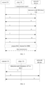
FIG. 3 is a schematic diagram showing interaction of a link configuration method according to an embodiment of the present disclosure; -
FIG. 4 is a schematic diagram showing interaction of a link configuration method according to an embodiment of the present disclosure; -
FIG. 5 is a flowchart of a link configuration method according to an embodiment of the present disclosure; -
FIG. 6 is a schematic diagram of a link configuration apparatus according to an embodiment of the present disclosure; -
FIG. 7 is a schematic diagram of a link configuration apparatus according to an embodiment of the present disclosure; -
FIG. 8 is a schematic diagram of a remote UE according to an embodiment of the present disclosure; and -
FIG. 9 is a schematic diagram of a network device according to an embodiment of the present disclosure. - In the related art, the following two network access schemes are provided for a remote UE (Remote UE):
- Scheme 1: the remote UE may choose to access the network device, such as a base station, via an NR direct link or a non-direct link. For example, the remote UE selects, according to predefined selection criteria, the NR direct link or the relay UE to access the network device. That is, the remote UE can directly switch between the NR direct link and the non-direct link. For a connected remote UE, the remote UE reports measurement information to the network device and performs relay UE reselection or switches to the NR direct link based on configurations delivered by the network device. However, the
scheme 1 suffers from low network throughput. - Scheme 2: as shown in
FIG. 1 , the remote UE accesses the network device simultaneously through a relay UE and an NR direct link, where Uu interface is used for communication between the UE and the network device, and PC5 interface is used for communication between UEs. - In one scenario, the remote UE may first establish a connection with the network device through the relay UE; the remote UE reports measurement information to the network device and establishes an NR direct connection (i.e., adding an NR direct link) based on configurations delivered by the network device. In another scenario, the remote UE may first establish an NR direct connection; the remote UE reports measurement information to the network device and selects and adds an indirect link based on configurations delivered by the network device.
- In the
scheme 2, after adding the NR direct link or indirect link, the remote UE operates in a multi-connectivity mode. For the added NR direct link or indirect link, there may be one or more Radio Bearers (RBs) to improve system transmission reliability or throughput. - Although the
scheme 2 improves network throughput, in thescheme 2, SRB1 and SRB2 are established on an initially established path. When the initially established path fails, both SRB1 and SRB2 become unavailable, resulting in communication failure between the remote UE and the network device, which results in insufficient network robustness due to over-reliance on the initially established path. - For example, when the remote UE establishes a Radio Resource Control (RRC) connection with the network device through the relay UE,
SRB 1/SRB2 and Data Radio Bearer (DRB) are established via the relay UE; if the indirect link between the remote UE and the network device fails,SRB 1 and SRB2 become unavailable, resulting in insufficient network robustness. When the remote UE directly establishes an RRC connection with the network device,SRB 1/SRB2 and DRB are established between the remote UE and the network device, and only Split DRB exists on the relay UE; if the NR direct link between the remote UE and the network device fails,SRB 1 and SRB2 become unavailable, resulting in insufficient network robustness. - In view of this, in the embodiments of the present disclosure, the network device configures a first SRB and/or a second SRB on a first link to the remote UE; where the first link represents an NR direct link or an indirect link; the remote UE obtains the first SRB and/or the second SRB configured by the network device on the first link to the remote UE. Since the first SRB and/or the second SRB are configured on the first link to the remote UE, rather than on an initially established path between the remote UE and the network device, the first SRB and/or the second SRB will not become unavailable due to failure of the initially established path, thereby improving network robustness and reliability.
- The present disclosure is further described in detail hereinafter with reference to the accompanying drawings and embodiments.
- One embodiment of the present disclosure provides a link configuration method, applied to a network device which includes a base station. The method includes:
configuring a first SRB and/or a second SRB on a first link to a UE. - The first link represents an NR direct link or a non-direct link. The NR direct link refers to a link through which the UE (e.g., remote UE) is directly connected to the network device; the non-direct link may be an indirect link, sidelink, or non-standard link. The indirect link is also referred to as a PC5 link.
- The UE may be a remote UE.
- One embodiment of the present disclosure further provides a link configuration method, applied to a network device which includes a base station. Referring to
FIG. 2 , the method includes:
Step 201: configuring a first SRB and/or a second SRB on a first link to a remote UE. - The first link represents an NR direct link or an indirect link. The NR direct link refers to a link through which the remote UE is directly connected to the network device; the indirect link is also referred to as a PC5 link.
- Here, in a scenario where the remote UE first accesses the network device through a remote UE and then adds an NR direct link, the network device configures the first SRB and/or the second SRB on the NR direct link to the remote UE.
- In a scenario where the remote UE first accesses the network device through an NR direct link and then adds an indirect link, the network device configures the first SRB and/or the second SRB on the NR direct link to the remote UE.
- It should be noted that the first SRB and the second SRB may be used to transmit RRC signaling and/or Non-Access Stratum (NAS) signaling. The first SRB includes Split SRB1, and the second SRB includes Split SRB2.
- Taking
FIG. 3 as an example, an implementation process of configuring the first SRB and/or the second SRB by the network device is described. As shown inFIG. 3 , the link configuration method includes: - Step 1: the remote UE performs measurement based on measurement configuration delivered by the network device and reports a measurement result to the network device;
- Step 2: the network device sends an RRC Reconfiguration Message to the remote UE;
- Step 3: the remote UE sends a preamble to the network device;
- Step 4: the network device sends a Random Access Response (RAR) to the remote UE;
- Step 5: the remote UE sends an RRC Setup Request to the network device;
- Step 6: the network device sends an RRC Setup Message to the remote UE.
- It is to be noted that the remote UE and the network device complete random access through the
steps 3 to 6. The RRC Setup Message is sent by the network device via SRB0. The RRC Setup Message includes configurations related to the first SRB, i.e., the network device configures the first SRB through the RRC Setup Message. The first SRB is Split SRB1. - Step 7: the remote UE sends an RRC Setup Complete Message to the network device.
- Step 8: the network device sends an RRC Reconfiguration Message to the remote UE.
- The RRC Reconfiguration Message includes configurations related to the second SRB, i.e., the network device configures the second SRB through the RRC Reconfiguration Message. The second SRB is Split SRB2.
- Step 9: the network device sends an RRC Reconfiguration Complete Message to the remote UE.
- In the scenario where the remote UE first accesses the network device through a remote UE and then adds an NR direct link, in one embodiment, the configuring the first SRB and/or the second SRB on the first link to the remote UE includes:
on the NR direct link to the remote UE, adding and activating Split SRB1, and/or adding and activating Split SRB2. - For example, when the remote UE first accesses the network device through a remote UE and then adds an NR direct link, the network device adds
Split SRB 1 on the NR direct link to the remote UE and activates the added Split SRB1. - For another example, when the remote UE first accesses the network device through a remote UE and then adds an NR direct link, the network device adds Split SRB2 on the NR direct link to the remote UE and activates the added Split SRB2.
- For another example, when the remote UE first accesses the network device through the remote UE and then adds an NR direct link, the network device adds and activates
Split SRB 1 and adds and activates Split SRB2, on the NR direct link to the remote UE. - It is to be noted that in the scenario where the remote UE first accesses the network device through the remote UE and then adds the NR direct link, there are
SRB 1 and/orSRB 1 on the indirect link between the remote UE and the network device. SRB2. Therefore, even if the indirect link between the remote UE and the network device fails, the remote UE can still useSplit SRB 1 and/or Split SRB2 on the NR direct link to transmit relevant signaling to maintain communication between the remote UE and the network device, thereby improving reliability and stability of the network. - In the scenario where the remote UE first accesses the network device through the remote UE and then adds an NR direct link,
SRB 1 and/or SRB2 exist on the indirect link between the remote UE and the network device. Based on this, in one embodiment, the method further includes: - deactivating
SRB 1 and/or SRB2 on the indirect link; or - keeping
SRB 1 and/or SRB2 on the indirect link in active state. - Here, when the remote UE first accesses the network device through the remote UE and then adds an NR direct link, when
SRB 1 on the indirect link is in an active state, the network device deactivatesSRB 1 on the indirect link; when SRB2 on the indirect link is in an active state, the network device deactivates SRB2 on the indirect link; when bothSRB 1 and SRB2 on the indirect link are in the active state, the network device deactivatesSRB 1 and SRB2 on the indirect link. The SRB in the active state can transmit relevant signaling, and the SRB in an inactive state cannot transmit relevant signaling. - Of course, when the remote UE first accesses the network device through the remote UE and then adds an NR direct link, the network device can also keep
SRB 1 and/or SRB2 carried on the indirect link in the active state. At this point, the network device and the remote UE can use the activated SRB on the NR direct link and indirect link to transmit relevant signaling. - In a scenario where the remote UE first accesses the network device through an NR direct link and then adds an indirect link, in one embodiment, the configuring a first SRB and/or a second SRB on a first link to the remote UE, includes at least one of the following:
- on the indirect link to the remote UE, adding Split SRB1 and configuring the Split SRB1 to be in an inactive state;
- on the indirect link to the remote UE, adding Split SRB2 and configuring the Split SRB2 to be in an inactive state;
- on the indirect link to the remote UE, adding and activating Split SRB1;
- on the indirect link to the remote UE, adding and activating Split SRB2.
- Here, when the remote UE first accesses the network device through the NR direct link and then adds an indirect link, the network device adds
Split SRB 1 and/or Split SRB2 on the indirect link to the remote UE. The network device can activate or deactivate the added Split SRB1 and/or Split SRB2. Specific details are as follows. - The network device can add
Split SRB 1 on the indirect link to the remote UE, and configure theSplit SRB 1 to be in an inactive state. At this point, the addedSplit SRB 1 is in the inactive state by default. - When the remote UE first accesses the network device through the NR direct link and then adds an indirect link, the network device can add Split SRB2 on the indirect link to the remote UE and configure the Split SRB2 is in an inactive state. At this point, the added Split SRB2 is in the inactive state by default.
- When the remote UE first accesses the network device through the NR direct link and then adds an indirect link, the network device can add and activate
Split SRB 1 on the indirect link to the remote UE. At this point, the network device and the remote UE can use the activated Split SRB1 on the indirect link to transmit relevant signaling. - When the remote UE first accesses the network device through the NR direct link and then adds an indirect link, the network device can add and activate Split SRB2 on the indirect link to the remote UE. At this point, the network device and the remote UE can use the activated Split SRB2 on the indirect link to transmit relevant signaling.
- It is to be noted that in the scenario where the remote UE first accesses the network device through the NR direct link and then adds an indirect link, there are SRB1 and/or SRB2 on the NR direct link between the remote UE and the network device. Therefore, even if the NR direct link between the remote UE and the network device fails, the remote UE can still use
Split SRB 1 and/or Split SRB2 on the indirect link to transmit relevant signaling to maintain communication between the remote UE and the network device, thereby improving the reliability and stability of the network. - In the scenario where the remote UE first accesses the network device through the NR direct link and then adds an indirect link, there are
SRB 1 and/or SRB2 on the NR direct link between the remote UE and the network device. Based on this, in one embodiment, the method further includes:
during activation of the NR direct link, keepingSRB 1 and/or SRB2 on the NR direct link in the active state. - Here, during activation of the NR direct link, the network device keeps
SRB 1 and/or SRB2 on the NR direct link in an active state. As a result, the network device and the remote UE can use the activated SRB on the NR direct link and indirect link to transmit relevant signaling. - In the scenario where the remote UE first accesses the network device through the remote UE and then adds an NR direct link, when the added NR direct link is unavailable or fails, in order to quickly restore the radio link to improve robustness of the radio link and avoid the network device and the remote UE from performing RRC connection reestablishment to reconfigure the SRB, in one embodiment, the method further includes:
activatingSRB 1 and/or SRB2 on the indirect link if any of the following conditions is met: - deleting or deactivating the NR direct link;
- RLF occurring on the NR direct link;
- reconfiguring the indirect link as a primary path.
- Here, in a scenario where the remote UE first accesses the network device through the remote UE and then adds an NR direct link,
SRB 1 and/or SRB2 exist on the indirect link between the remote UE and the network device. When any of the above conditions is met, the network device activatesSRB 1 and/or SRB2 on the indirect link, so that the network device and the remote UE use the activatedSRB 1 and/or SRB2 on the indirect link to transmit related signaling, to enable the network device and the remote UE to communicate normally. - For example, when the network device deletes or deactivates the NR direct link, the NR direct link does not exist or is unavailable. At this point, the network device activates
SRB 1 and/or SRB2 on the indirect link, so that the network device and the remote UE use the activatedSRB 1 and/or SRB2 on the indirect link to transmit relevant signaling. - For another example, when RLF occurs on the NR direct link, the NR direct link is unavailable. At this point, the network device activates
SRB 1 and/or SRB2 on the indirect link, so that the network device and the remote UE use the activatedSRB 1 and/or SRB2 on the indirect link to transmit relevant signaling. - For another example, when the network device reconfigures the indirect link as the primary path, the network device activates
SRB 1 and/or SRB2 on the indirect link, so that the network device and the remote UE preferentially use the SRB on the primary path to transmit relevant signaling. - When the remote UE first accesses the network device through the remote UE and then adds the NR direct link, in case that the indirect link is unavailable or fails, in order to quickly restore the radio link to improve robustness of the radio link property and avoid the network device and the remote UE from performing RRC connection reestablishment to reconfigure the SRB, in one embodiment, the method further includes:
reconfiguringSplit SRB 1 on the NR direct link asSRB 1, and/or reconfiguring Split SRB2 on the NR direct link as SRB2, if any of the following conditions is met: - adding NR direct link by the remote UE;
- deleting or deactivating an indirect link;
- Relay UE air interface radio link fails and RLF occurs;
- SL between the relay UE and the remote UE fails;
- reconfiguring the NR direct link as the primary path.
- In one embodiment, the method further includes:
reconfiguringSplit SRB 1 on the NR direct link asSRB 1, and/or reconfiguring Split SRB2 on the NR direct link as SRB2, If any of the following conditions is met: - deleting or deactivating an indirect link;
- RLF occurs on the relay UE;
- RLF occurs on the PC5 link;
- reconfiguring the NR direct link as the primary path.
- Here, after the remote UE first accesses the network device through the remote UE and then adds the NR direct link, if any of the above conditions is met, the network device reconfigures Split SRB1 on the NR direct link to SRB1, and/or, reconfigures Split SRB2 on the NR direct link to SRB2, so that the network device and the remote
UE use SRB 1 and/or SRB2 on the NR direct link to transmit relevant signaling, thereby enabling the network device and the remote UE to communicate normally. The occurrence of RLF in the relay UE includes failure of the remote UE, occurrence of RLF in the NR link of the remote UE. - When the network device configures Split SRB1 on the NR direct link, the network device reconfigures Split SRB1 on the NR direct link as
SRB 1. When the network device configures Split SRB2 on the NR direct link, the network device reconfigures Split SRB2 on the NR direct link as SRB2. When the network device configures Split SRB1 and Split SRB2 on the NR direct link, the network device can reconfigure Split SRB1 on the NR direct link as SRB1, and/or, reconfigure Split SRB2 on the NR direct link as SRB2. - Taking
FIG. 4 as an example, an implementation process of the network device reconfiguring the Split SRB on the NR direct link to corresponding SRB when the indirect link is unavailable or fails, is described hereinafter. - Step 1: when the relay UE detects that its NR radio link fails, that is, the relay UE's Uu-RLF link fails, the relay UE sends a PC5-RRC message to the remote UE.
- Step 2: the remote UE sends an RRC Reestablishment Request Message or RLF report to the network device.
- Here, when the remote UE receives the PC5-RRC message, the remote UE initiates ab RRC reestablishment process by using the activated Split SRB1 and/or Split SRB2 on the NR direct link to directly send an RRC Reestablishment Request Message to the network device. Different from the related art, when the remote UE initiates the RRC reestablish procedure, the remote UE does not need to initiate reestablishment of SRB1 and/or SRB2 and corresponding Packet Data Convergence Protocol (PDCP) and Radio Link Control (RLC), which can reduce processing delay.
- Alternatively, when the remote UE receives the PC5-RRC message, the remote UE can also send an RLF report (which may also be called relay UE RLF report) to the network device through the activated Split SRB1 and/or Split SRB2 on the NR direct link without initiating the RRC reestablishment procedure. The RLF report includes relay UE ID and RLF cause of the remote UE. The RLF cause includes at least one of the following:
- RLF occurs on the PC5 link;
- RLF occurs on the relay UE, which may specifically include the RLF cause of the relay UE.
- The occurrence of RLF in the remote UE may include occurrence of RLF in the NR link of the remote UE.
- Step 3: the network device sends an RRC Reconfiguration Message to the remote UE.
- Here, after the network device receives the RRC Reestablishment Request Message sent by the remote UE, the network device sends an RRC Reconfiguration Message to the remote UE based on RRC Reestablishment Request Message, to reconfigure the remote UE, which specifically includes: reconfiguring
Split SRB 1 on the NR direct link as SRB1, and/or, reconfiguring Split SRB2 on the NR direct link as SRB2. - When the network device receives the RLF report sent by the remote UE, based on the received RLF report, the network device sends an RRC Reconfiguration Message to the remote UE to reconfigure the remote UE, specifically including: reconfiguring
Split SRB 1 on the NR direct link as SRB1, and/or, reconfiguring split SRB2 on the NR direct link as SRB2. The network device can also perform further processing based on the RLF cause of the remote UE included in the RLF report. For example, when the RLF report includes an RLF occurrence in the NR link of the relay UE, the network device restores the NR link of the relay UE; when the RLF report includes an RLF occurrence in the PC5 link, the network device sends relevant information of the relay UE, such as the mobility of the relay UE, to the remote UE connected to the relay UE. - It is to be noted that, in one embodiment, the
step 1 inFIG. 4 can be omitted, that is, when RLF occurs in the PC5 link of the relay UE, the relay UE does not need to send a PC5-RRC message to the remote UE; when the remote UE detects that RLF occurs in the PC5 link, the remote UE sends an RRC Reestablishment Request Message or an RLF report to the network device. - In the case where the remote UE first accesses the network device through the NR direct link and then adds the indirect link, when the NR direct link is unavailable or fails, in order to quickly restore the radio link to improve robustness of the radio link property and avoid the network device and the remote UE from performing RRC connection reestablishment to reconfigure the SRB, in one embodiment, the method further includes:
- reconfiguring
Split SRB 1 on the indirect link asSRB 1, and/or reconfiguring Split SRB2 on the indirect link as SRB2, if any of the following condition is met: - deleting or deactivating the NR direct link;
- RLF occurring on the NR direct link;
- reconfiguring the indirect link as the primary path.
- Here, when the remote UE first accesses the network device through the NR direct link and then adds an indirect link, there is SRB1 and/or SRB2 on the NR direct link between the remote UE and the network device. When any of the above conditions is met, the network device reconfigures Split SRB1 on the indirect link as SRB1, and/or reconfigures Split SRB2 on the indirect link as SRB2. Therefore, there is no need to reconfigure
SRB 1 and/or SRB2 through RRC reestablishment. The network device and the remote UE can useSRB 1 and/or SRB2 on the indirect link to transmit relevant signaling, so that the network device and the remote UE can communicate normally. - When the network device configures
Split SRB 1 on the indirect link, the network device reconfiguresSplit SRB 1 on the indirect link asSRB 1. When the network device configures Split SRB2 on the indirect link, the network device reconfigures Split SRB2 on the indirect link as SRB2. In the case where the network device configures Split SRB1 and Split SRB2 on the indirect link, the network device can reconfigure Split SRB1 on the indirect link as SRB1, and/or, reconfigure Split SRB2 on the indirect link as SRB2. - It is to be noted that when Split SRB1 on the indirect link is in an inactive state, the network device first activates Split SRB1 on the indirect link, and then reconfigures Split SRB1 on the indirect link as SRB1; when Split SRB2 on the indirect link is inactive, the network device first activates Split SRB2 on the indirect link, and then reconfigures Split SRB2 on the indirect link as SRB2.
- In a scenario where the remote UE first accesses the network device through a relay UE and then adds an NR direct link, in order to reasonably utilize SRB, in one embodiment, the method further includes:
when the remote UE adds or activates the NR direct link, configuring the NR direct link as the primary path and configuring the indirect link as a secondary path. - Here, when the remote UE adds or activates an NR direct link, the network device configures the NR direct link as the primary path and configures the indirect link as the secondary path. At this point, the network device and the remote UE preferentially use the activated SRB on the NR direct link to transmit relevant signaling.
- In a scenario where the remote UE first accesses the network device through an NR direct link and then adds an indirect link, in order to reasonably utilize SRB, in one embodiment, the method further includes:
when the remote UE adds or activates an indirect link, configuring the indirect link as a primary path, and configuring the NR direct link as a secondary path. - Here, when the remote UE adds or activates an indirect link, the network device configures the indirect link as the primary path, and configures the NR direct link as the secondary path. At this point, the network device and the remote UE preferentially use the activated SRB on the indirect link to transmit relevant signaling.
- On the basis that the network device configures the primary path and the secondary path, in one embodiment, the method further includes:
- deactivating relevant SRB on the secondary path; or
- keeping relevant SRBs on both the primary path and the secondary path in the active state.
- Here, when the remote UE first accesses the network device through the relay UE and then adds the NR direct link, since the network device configures the added NR direct link as the primary path and configures the indirect link as the secondary path, the network device can deactivate
SRB 1 and/or SRB2 on the indirect link, so that the network device and the remote UE use only the activated SRB on the NR direct link to transmit relevant signaling. The network device can also keepSplit SRB 1 and/or Split SRB2 on the NR direct link andSRB 1 and/or SRB2 on the indirect link active, so that the network device and the remote UE can use activated SRB on the NR direct link and indirect link to transmit relevant signaling. - When the remote UE first accesses the network device through the NR direct link and then adds an indirect link, since the network device configures the added indirect link as the primary path and configures the NR direct link as the secondary path, therefore, the network device can deactivate SRB1 and/or SRB2 on the NR direct link, so that the network device and the remote UE use only the activated SRB on the indirect link to transmit relevant signaling. The network device can also keep Split SRB1 and/or Split SRB2 on the indirect link and SRB1 and/or SRB2 on the NR direct link in the active state, so that the network device and the remote UE use the activated SRB on the NR direct link and indirect link to transmit related signaling.
- Correspondingly, one embodiment of the present disclosure further provides a link configuration method, which is applied to remote UE. Referring to
FIG. 5 , the method includes:
Step 501: obtaining first SRB and/or second SRB configured by a network device on a first link to the remote UE. - The first link represents an NR direct link or an indirect link.
- Here, when the first link is to the remote UE, the remote UE obtains the first SRB and/or the second SRB configured by the network device on the added first link. The first SRB includes Split SRB1, and the second SRB includes Split SRB2.
- For example, when the remote UE first accesses the network device through a relay UE and then adds an NR direct link, the remote UE obtains the Split SRB1 and/or Split SRB2 configured by the network device on the added NR direct link.
- For another example, when the remote UE first accesses the network device through the NR direct link and then adds an indirect link, the remote UE obtains the Split SRB1 and/or Split SRB2 configured by the network device on the added indirect link.
- In one embodiment, the method further includes:
preferentially using relevant SRB on the primary path to transmit relevant signaling. - Here, when the network device configures the primary path and the secondary path, the remote UE preferentially uses the relevant SRB on the primary path to transmit relevant signaling, such as RRC signaling and NAS signaling.
- For example, in a scenario where the remote UE first accesses the network device through a relay UE and then adds an NR direct link, since the network device configures the NR direct link as the primary path and the indirect link as the secondary path, therefore, the remote UE preferentially uses the activated
Split SRB 1 and/or Split SRB2 on the NR direct link to transmit relevant signaling. - For another example, in the scenario where the remote UE first accesses the network device through the NR direct link and then adds an indirect link, since the network device configures the indirect link as the primary path and configures the NR direct link as the secondary path, the remote UE preferentially uses the activated Split SRB1 and/or Split SRB2 on the indirect link to transmit relevant signaling.
- The embodiments of the present disclosure will be further described hereinafter in conjunction with specific application scenarios.
- In an application scenario where the remote UE first accesses the network device through a relay UE and then adds an NR direct link, the link configuration method is as follows.
- Step 1: the network device configures a first SRB and/or a second SRB on the NR direct link to the remote UE.
- Here, when the remote UE first accesses the network device through the relay UE and then adds an NR direct link, the network device adds and activates Split SRB1 and/or Split SRB2, on the NR direct link to the remote UE.
- In one embodiment, the network device may further deactivate
SRB 1 and/or SRB2 on the indirect link; or, keep SRB1 and/or SRB2 on the indirect link in an active state. - Here, when the network device deactivates SRB1 and/or SRB2 on the indirect link, the network device and the remote UE use only the activated SRB on the NR direct link to transmit relevant signaling.
- When the network device keeps
SRB 1 and/or SRB2 on the indirect link in the active state, the network device and the remote UE can use the activated SRB on the NR direct link and the indirect link to transmit relevant signaling. - In one embodiment, the method further includes:
- activating, by the network device,
SRB 1 and/or SRB2 on the indirect link, if any of the following condition is met: - deleting or deactivating the NR direct link;
- RLF occurring on the NR direct link;
- reconfiguring the indirect link as the primary path.
- In one embodiment, the method further includes:
reconfiguring, by the network device,Split SRB 1 on the NR direct link as SRB1, and/or reconfiguring, by the network device, Split SRB2 on the NR direct link as SRB2, if any of the following condition is met: - deleting or deactivating the indirect link;
- RLF occurring on the relay UE;
- RLF occurring on the PC5 link;
- reconfiguring the NR direct link as the primary path.
- In one embodiment, the method further includes:
when the remote UE adds or activates an NR direct link, configuring, by the network device, the NR direct link as a primary path, and configuring the indirect link as a secondary path. - On the basis that the network device configures the primary path and the secondary path, in one embodiment, the method further includes:
- deactivating, by the network device, the relevant SRB on the secondary path; or
- keeping, by the network device, the relevant SRB on the primary path and the secondary path in an activated state.
- Step 2: the remote UE obtains the first SRB and/or the second SRB configured by the network device on the added NR direct link.
- On the basis that the network device configures a primary path and a secondary path, the remote UE preferentially uses the SRB on the primary path to transmit relevant signaling.
- In an application scenario where the remote UE first accesses the network device through an NR direct link and then adds an indirect link, the link configuration method is as follows.
- Step 1: the network device configures the first SRB and/or the second SRB on the indirect link to the remote UE.
- Here, when the remote UE first accesses the network device through the NR direct link and then adds an indirect link,
Here, when the remote UE first accesses the network device through the NR direct link and then adds the indirect link, configuring, by the network device, the first SRB and/or the second SRB on the indirect link to the remote UE, includes at least one of the following: - on the indirect link to the remote UE, adding Split SRB1 and configuring the Split SRB1 to be inactive;
- on the indirect link to the remote UE, adding Split SRB2 and configuring the Split SRB2 to be inactive;
- on the indirect link to the remote UE, adding and activating Split SRB1;
- on the indirect link to the remote UE, adding and activating Split SRB2.
- In one embodiment, the method further includes:
during duration of activation of the NR direct link, keeping, by the network device, SRB1 and/or SRB2 on the NR direct link in the active state. - In one embodiment, the method further includes:
reconfiguring, by the network device, Split SRB1 on the indirect link as SRB1, and/or reconfiguring Split SRB2 on the indirect link as SRB2, if any of the following condition is met: - deleting or deactivating the NR direct link;
- RLF occurring on the NR direct link;
- reconfiguring the indirect link as the primary path.
- Here, after the remote UE first accesses the network device through the NR direct link and then adds the indirect link, if any of the above condition is met, the network device reconfigures Split SRB1 on the indirect link as SRB1, and/or, reconfigures Split SRB2 on the indirect link as SRB2.
- It is to be noted that when
Split SRB 1 on the indirect link is in an inactive state, the network device first activates Split SRB1 on the indirect link, and then reconfigures Split SRB1 on the indirect link as SRB1; when the Split SRB2 on the indirect link is inactive, the network device first activates Split SRB2 on the indirect link, and then reconfigures Split SRB2 on the indirect link as SRB2. - In one embodiment, the method further includes:
when the remote UE adds or activates an indirect link, configuring, by the network device, the indirect link as the primary path and configuring the NR direct link as the secondary path. - On the basis that the network device configures the primary path and the secondary path, in an embodiment, the method further includes:
- deactivating, by the network device, the relevant SRB on the secondary path; or,
- keeping, by the network device, the relevant SRBs on both the primary path and the secondary path in the active state.
- Step 2: the remote UE obtains the first SRB and/or the second SRB configured by the network device on the added indirect link.
- On the basis that the network device configures the primary path and the secondary path, the remote UE preferentially uses the SRB on the primary path to transmit relevant signaling.
- In the link configuration method, apparatus, remote UE, network device and storage medium provided in the embodiments of the present disclosure, the network device configures the first SRB and/or the second SRB on the first link to the remote UE, where the first link represents an NR direct link or an indirect link; the remote UE obtains the first SRB and/or the second SRB configured by the network device on the first link to the remote UE. Since the first SRB and/or the second SRB are configured on the first link to the remote UE, rather than on the path initially established between the remote UE and the network device, the first SRB and/or the second SRB will not become unavailable due to failure of the initially established path, thereby improving network robustness and reliability.
- In order to implement the link configuration method of the embodiment of the present disclosure, one embodiment of the present disclosure further provides a link configuration apparatus, which is provided on a network device. As shown in
FIG. 6 , the apparatus includes:
afirst configuration unit 61 used to configure a first SRB and/or a second SRB on a first link to a remote UE; where the first link represents an NR direct link or an indirect link. - In one embodiment, the
first configuration unit 61 is specifically used to add and activateSplit SRB 1 and/or add and activate Split SRB2, on the NR direct link to the remote UE. - In one embodiment, the apparatus further includes:
- a second configuration unit used to deactivate
SRB 1 and/or SRB2 on the indirect link; or, - keep
SRB 1 and/or SRB2 on the indirect link active. - In one embodiment, the
first configuration unit 61 is specifically used for at least one of the following: - on the indirect link to the remote UE, adding
Split SRB 1 and configuring theSplit SRB 1 to be in an inactive state; - on the indirect link to the remote UE, adding Split SRB2 and configuring the Split SRB2 to be in an inactive state;
- on the indirect link to the remote UE, adding and activating
Split SRB 1; - on the indirect link to the remote UE, adding and activating Split SRB2.
- In one embodiment, the apparatus further includes:
a third configuration unit used to, during activation of the NR direct link, keepSRB 1 and/or SRB2 on the NR direct link in the active state. - In one embodiment, the apparatus further includes:
a fourth configuration unit used to activateSRB 1 and/or SRB2 on the indirect link if any of the following conditions is met: - deleting or deactivating the NR direct link;
- RLF occurring on the NR direct link;
- reconfiguring the indirect link as a primary path.
- In one embodiment, the apparatus further includes:
a fifth configuration unit used to reconfigureSplit SRB 1 on the NR direct link as SRB1, and/or reconfigure Split SRB2 on the NR direct link as SRB2, if any of the following conditions is met: - deleting or deactivating an indirect link;
- RLF occurring on the remote UE;
- RLF occurring on the PC5 link;
- reconfiguring the NR direct link as the primary path.
- In one embodiment, the apparatus further includes:
a fifth configuration unit used to reconfigureSplit SRB 1 on the NR direct link as SRB1, and/or reconfigure Split SRB2 on the NR direct link as SRB2, if any of the following condition is met: - adding NR direct link by the remote UE;
- deleting or deactivating an indirect link;
- Relay UE air interface radio link fails and RLF occurs;
- SL between the relay UE and the remote UE fails;
- reconfiguring the NR direct link as the primary path.
- In one embodiment, the apparatus further includes:
a sixth configuration unit used to reconfigureSplit SRB 1 on the indirect link as SRB1, and/or reconfigure Split SRB2 on the indirect link as SRB2, if any of the following condition is met: - deleting or deactivating the NR direct link;
- RLF occurring on the NR direct link;
- reconfiguring the indirect link as a primary path.
- In one embodiment, the apparatus further includes:
a seventh configuration unit used to configure the NR direct link as the primary path and configure the indirect link as the secondary path, when the remote UE adds or activates the NR direct link. - In one embodiment, the apparatus further includes:
an eighth configuration unit used to configure the indirect link as the primary path and configure the NR direct link as the secondary path, when the remote UE adds or activates the indirect link. - In one embodiment, the apparatus further includes:
- a ninth configuration unit used to deactivate relevant SRB on the secondary path; or
- keep relevant SRBs on both the primary path and the secondary path in the active state.
- In actual application, the
first configuration unit 61, the second configuration unit, the third configuration unit, the fourth configuration unit, the fifth configuration unit, the sixth configuration unit, the seventh configuration unit, the eighth configuration unit and the ninth configuration unit can be accomplished by a processor in the link configuration apparatus in conjunction with a communication interface. - It is to be noted that the link configuration apparatus provided in the above embodiment only takes division of the above program modules as an example to illustrate the link configuration. In practical applications, the above processing can be assigned to different program modules as needed, that is, an internal structure of the apparatus is divided into different program modules to complete all or part of the processing described above. In addition, the link configuration apparatus provided in the above embodiment and the link configuration method embodiment on the network device side belong to the same concept, and the specific implementation process is detailed in the method embodiment, which will not be repeated here.
- In order to implement the link configuration method of the embodiment of the present disclosure, one embodiment of the present disclosure further provides a link configuration apparatus, which is provided on a remote UE. As shown in
FIG. 7 , the apparatus includes:
an obtainingunit 71 used to obtain a first SRB and/or a second SRB configured by a network device on a first link to the remote UE; where the first link represents an NR direct link or indirect link. - In one embodiment, the apparatus further includes:
a transmission unit used to preferentially use relevant SRB on the primary path to transmit relevant signaling. - In actual application, the obtaining
unit 71 and the transmission unit can be implemented by a processor in the link configuration apparatus in conjunction with a communication interface. - It is to be noted that the link configuration apparatus provided in the above embodiment only takes division of the above program modules as an example to illustrate the link configuration. In practical applications, the above processing can be assigned to different program modules as needed, that is, an internal structure of the apparatus is divided into different program modules to complete all or part of the processing described above. In addition, the link configuration apparatus provided in the above embodiment and the link configuration method embodiment on the remote UE side belong to the same concept, and the specific implementation process is detailed in the method embodiment, which will not be repeated here.
- Based on the hardware implementation of the above program module, and in order to implement the method on the network device side of the embodiment of the present disclosure, one embodiment of the present disclosure further provides a network device. As shown in
FIG. 8 , thenetwork device 8 includes: - a
first communication interface 801 capable of exchanging information with other network nodes; - a
first processor 802 connected to thefirst communication interface 801 to implement information interaction with other network nodes, and used to execute the method provided by one or more technical solutions on the network device side when running a computer program. The computer program is stored on afirst memory 803. - Specifically, the
first processor 802 configures a first signaling radio bearer (SRB) and/or a second SRB on a first link to the remote UE; where the first link represents a new radio (NR) direct link or indirect link. - In one embodiment, the
first processor 802 is specifically used to add and activateSplit SRB 1 and/or add and activate Split SRB2, on the NR direct link to the remote UE. - In one embodiment, the
first processor 802 is further used to deactivateSRB 1 and/or SRB2 on the indirect link; or keepSRB 1 and/or SRB2 on the indirect link in an active state. - In one embodiment, the
first processor 802 is specifically used for at least one of the following: - on the indirect link to the remote UE, adding
Split SRB 1 and configuring theSplit SRB 1 to be in an inactive state; - on the indirect link to the remote UE, adding Split SRB2 and configuring the Split SRB2 to be in an inactive state;
- on the indirect link to the remote UE, adding and activating
Split SRB 1; - on the indirect link to the remote UE, adding and activating Split SRB2.
- In one embodiment, the
first processor 802 is further used to keepSRB 1 and/or SRB2 on the NR direct link in an active state during duration of activation of the NR direct link. - In one embodiment, the
first processor 802 is further used to: - activate
SRB 1 and/or SRB2 on the indirect link if any of the following is met: - deleting or deactivating the NR direct link;
- RLF occurring on the NR direct link;
- reconfiguring the indirect link as a primary path.
- In one embodiment, the
first processor 802 is further used to:
reconfigureSplit SRB 1 on the NR direct link as SRB1, and/or reconfigure Split SRB2 on the NR direct link as SRB2, if any of the following conditions is met: - deleting or deactivating an indirect link;
- RLF occurring on the remote UE;
- RLF occurring on the PC5 link;
- reconfiguring the NR direct link as the primary path.
- In one embodiment, the
first processor 802 is further used to,
reconfigureSplit SRB 1 on the NR direct link as SRB1, and/or reconfigure Split SRB2 on the NR direct link as SRB2, if any of the following conditions is met: - adding NR direct link by the remote UE;
- deleting or deactivating the indirect link;
- Relay UE air interface radio link fails and RLF occurs;
- SL between the relay UE and the remote UE fails;
- reconfiguring the NR direct link as the primary path.
- In one embodiment, the
first processor 802 is further used to, - reconfigure
Split SRB 1 on the indirect link as SRB1, and/or reconfigure Split SRB2 on the indirect link as SRB2, if any of the following conditions is met: - deleting or deactivating the NR direct link;
- RLF occurring on the NR direct link;
- reconfiguring the indirect link as a primary path.
- In one embodiment, the
first processor 802 is further used to, when the remote UE adds or activates an NR direct link, configure the NR direct link as a primary path, and configure the indirect link as the secondary path. - In one embodiment, the
first processor 802 is further used to, when the remote UE adds or activates an indirect link, configure the indirect link as the primary path, and configure the NR direct link as the secondary path. - In one embodiment, the
first processor 802 is further used to deactivate the relevant SRB on the secondary path; or, keep the relevant SRB on the primary path and the secondary path in an active state. - It should be noted that the specific processing procedures of the
first processor 802 and thefirst communication interface 801 can be understood with reference to the above method. - Of course, in actual application, various components in the
network device 8 are coupled together through thebus system 804. It can be understood that thebus system 804 is used to implement connection communication between these components. In addition to data bus, thebus system 804 also includes a power bus, a control bus and a status signal bus. However, for the sake of clarity, various buses are all labeled as thebus system 804 inFIG. 8 . - The
first memory 803 in the embodiment of the present disclosure is used to store various types of data to support operations of thenetwork device 8. Examples of such data include: any computer program operated on thenetwork device 8. - The method disclosed in the above embodiments of the present disclosure can be applied in the
first processor 802 or implemented by thefirst processor 802. Thefirst processor 802 may be an integrated circuit chip with signal processing capabilities. During the implementation process, each step of the above method can be completed by an integrated logic circuit of hardware or software instructions in thefirst processor 802. The abovefirst processor 802 can be a general-purpose processor, a digital signal processor (DSP), or other programmable logic devices, discrete gates or transistor logic devices, discrete hardware components, etc. Thefirst processor 802 can implement or execute the methods, steps and logic block diagrams disclosed in the embodiments of the present disclosure. The general-purpose processor can be a microprocessor or any conventional processor, etc. In combination with the steps of the method disclosed in the embodiments of the present disclosure, it can be directly embodied as a hardware decoding processor to execute, or it can be executed by a combination of hardware and software modules in the decoding processor. The software module can be located in a storage medium, which is located in thefirst memory 803. Thefirst processor 802 reads information in thefirst memory 803 and completes the steps of the above method in combination with its hardware. - In an exemplary embodiment, the
network device 8 can be implemented by one or more application specific integrated circuits (ASIC), DSP, programmable logic device (PLD), complex programmable logic device (CPLD), field-programmable gate array (FPGA), general processor, controller, micro controller unit (MCU), microprocessor, or other electronic components, to execute the aforementioned method. - On the basis of the hardware implementation of the above program modules, and in order to implement the method on the remote UE side in the embodiment of the present disclosure, one embodiment of the present disclosure further provides a remote UE. As shown in
Figure 9 , theremote UE 9 includes: - a
second communication interface 901 capable of exchanging information with other network nodes; - a
second processor 902 connected to thesecond communication interface 901 to implement information interaction with other network nodes, and is used to execute the method provided by one or more technical solutions on the remote UE side when running a computer program. The computer program is stored on thesecond memory 903. - Specifically, the
second processor 902 is used to obtain a first SRB and/or a second SRB configured by a network device on a first link to the remote UE; where the first link represents an NR direct link or indirect link. - In one embodiment, the
second processor 902 is further used to: preferentially use relevant SRB on a primary path to transmit relevant signaling. - It is to be noted that the specific processing procedures of the
second processor 902 and thesecond communication interface 901 can be understood with reference to the above method. - Of course, in actual application, various components in the
remote UE 9 are coupled together through thebus system 904. It can be understood that thebus system 904 is used to implement connection communication between these components. In addition to data bus, thebus system 904 also includes a power bus, a control bus and a status signal bus. However, for the sake of clarity, various buses are labeled asbus system 904 inFIG. 9 . - The
second memory 903 in the embodiment of the present disclosure is used to store various types of data to support operations of theremote UE 9. Examples of such data include: any computer program operated on theremote UE 9. - The method disclosed in the above embodiments of the present disclosure can be applied to the
second processor 902 or implemented by thesecond processor 902. Thesecond processor 902 may be an integrated circuit chip with signal processing capabilities. During the implementation process, each step of the above method can be completed by an integrated logic circuit of hardware or software instructions in thesecond processor 902. The abovesecond processor 902 can be a general-purpose processor, a digital signal processor (DSP), or other programmable logic devices, discrete gates or transistor logic devices, discrete hardware components, etc. Thesecond processor 902 can implement or execute the methods, steps and logic block diagrams disclosed in the embodiments of the present disclosure. The general-purpose processor can be a microprocessor or any conventional processor, etc. In combination with the steps of the method disclosed in the embodiments of the present disclosure, it can be directly embodied as a hardware decoding processor to execute, or it can be executed by a combination of hardware and software modules in the decoding processor. The software module can be located in a storage medium, which is located in thesecond memory 903. Thesecond processor 902 reads information in thesecond memory 903 and completes the steps of the above method in combination with its hardware. - In an exemplary embodiment, the
remote UE 9 may be implemented by one or more ASICs, DSPs, PLDs, CPLDs, FPGAs, general-purpose processors, controllers, MCUs, Microprocessors, or other electronic components for performing the foregoing method. - It can be understood that the memory (
first memory 803, second memory 903) in the embodiment of the present disclosure may be a volatile memory or a non-volatile memory, or may include both volatile and non-volatile memory. The non-volatile memory can be read-only memory (ROM), programmable read-only memory (PROM), erasable programmable read-only memory (EPROM), Electrically Erasable Programmable Read-Only Memory (EEPROM), ferromagnetic random access memory (FRAM), Flash Memory, Magnetic Surface Memory, optical disk, or Compact Disc Read-Only Memory (CD-ROM); the magnetic surface memory can be a magnetic disk memory or a magnetic tape memory. The volatile memory may be Random Access Memory (RAM), which is used as an external cache. By way of illustration, but not limitation, many forms of RAM are available, such as Static Random Access Memory (SRAM), Synchronous Static Random Access Memory (SSRAM), Dynamic Random Access Memory (DRAM), synchronous dynamic random access memory (SDRAM), double data rate synchronous dynamic random access memory (DDRSDRAM), Enhanced Synchronous Dynamic Random Access Memory (ESDRAM), SyncLink Dynamic Random Access Memory (SLDRAM), Direct Rambus Random Access Memory (DRRAM). The memory described in embodiments of the present disclosure is intended to include, but is not limited to, these and any other suitable types of memory. - In an exemplary embodiment, one embodiment of the present disclosure further provides a storage medium, that is, a computer storage medium, specifically a computer-readable storage medium, for example, including a
first memory 803 storing a computer program. The above computer program can be executed by thefirst processor 802 of thenetwork device 8 to complete the steps of the network device side method. For another example, the storage medium includes asecond memory 803 storing the computer program, and the computer program can be executed by thesecond processor 802 of theremote UE 9 to complete the steps of the remote UE side method. The computer readable storage medium can be a memory such as FRAM, ROM, PROM, EPROM, EEPROM, Flash Memory, magnetic surface memory, optical disk, or CD-ROM. - It is to be noted that "first", "second", etc. are used to distinguish similar objects and are not necessarily used to describe a specific order or sequence.
- The term "and/or" in this article is only a description of association relationship of associated objects, indicating that there can be three relationships. For example, A and/or B can represent: A exists alone, A and B exist at the same time, and B exists alone. In addition, the term "at least one" in this article refers to any one of a plurality of elements or any combination of at least two of a plurality of elements. For example, at least one of A, B, and C may refer to any one or more elements selected from the set including A, B, and C.
- In addition, the technical solutions recorded in the embodiments of the present disclosure can be arbitrarily combined without conflict.
- The above descriptions are only preferred embodiments of the present disclosure and are not intended to limit the scope of the present disclosure.
Claims (20)
- A link configuration method, applied to a network device, the method comprising:
configuring a first signaling radio bearer (SRB) and/or a second SRB on a first link to a remote user equipment (UE); wherein the first link represents a new radio (NR) direct link or an indirect link. - The method according to claim 1, wherein the configuring the first SRB and/or the second SRB on the first link to the remote UE, includes:
adding and activating a split SRB1, and/or adding and activating a split SRB2, on the NR direct link to the remote UE. - The method according to claim 2, further comprising:deactivating the SRB1 and/or the SRB2 on the indirect link; orkeeping the SRB1 and/or the SRB2 on the indirect link in an active state.
- The method according to claim 1, wherein the configuring the first SRB and/or the second SRB on the first link to the remote UE, includes at least one of:adding a split SRB 1 on the indirect link to the remote UE and configuring the split SRB1 to be in an inactive state;adding a split SRB2 on the indirect link to the remote UE and configuring the split SRB2 to be in an inactive state;adding and activating a split SRB1 on the indirect link to the remote UE;adding and activating a split SRB2 on the indirect link to the remote UE.
- The method according to claim 4, further comprising:
during activation of the NR direct link, keeping the SRB1 and/or the SRB2 on the NR direct link in an active state. - The method according to any one of claims 1 to 3, further comprising:
activating SRB1 and/or SRB2 on the indirect link when any one of the following conditions is met:deletion or deactivation of the NR direct link;occurrence of a radio link failure (RLF) on the NR direct link;reconfiguration of the indirect link as a primary path. - The method according to any one of claims 1 to 3, further comprising:
reconfiguring a split SRB 1 on the NR direct link as SRB1, and/or reconfiguring a split SRB2 on the NR direct link as SRB2, when any one of the following conditions is met:the remote UE adding the NR direct link;deletion or deactivation of the indirect link;occurrence of RLF on an air interface of the remote UE;failure of a sidelink between a relay UE and the remote UE;reconfiguration of the NR direct link as a primary path. - The method according to claim 1, 4, or 5, further comprising:
reconfiguring a split SRB 1 on the indirect link as SRB1, and/or reconfiguring a split SRB2 on the indirect link as SRB2, when any one of the following conditions is met:deletion or deactivation of the NR direct link;occurrence of RLF on the NR direct link;reconfiguration of the indirect link as a primary path. - The method according to claim 1, further comprising:
when the remote UE adds or activates the NR direct link, configuring the NR direct link as a primary path and configuring the indirect link as a secondary path. - The method according to claim 1, further comprising:
when the remote UE adds or activates the indirect link, configuring the indirect link as a primary path and configuring the NR direct link as a secondary path. - The method according to claim 9 or 10, further comprising:deactivating related SRBs on the secondary path; orkeeping related SRBs on both the primary and secondary paths in an active state.
- A link configuration method, applied to a remote user equipment (UE), the method comprising:
obtaining a first signaling radio bearer (SRB) and/or a second SRB configured by a network device on a first link to the remote UE; wherein the first link represents a new radio (NR) direct link or an indirect link. - The method according to claim 12, further comprising:
prioritizing usage of related SRBs on a primary path to transmit related signaling. - A link configuration apparatus, comprising:
a first configuration unit used to configure a first signaling radio bearer (SRB) and/or a second SRB on a first link to a remote user equipment (UE); wherein the first link represents a new radio (NR) direct link or an indirect link. - A link configuration apparatus, comprising:
an obtaining unit used to obtain a first signaling radio bearer (SRB) and/or a second SRB configured by a network device on a first link to a remote user equipment (UE); wherein the first link represents a new radio (NR) direct link or an indirect link. - A network device, comprising: a first processor and a first communication interface;
wherein the first processor is used to configure a first signaling radio bearer (SRB) and/or a second SRB on a first link to a remote user equipment (UE); wherein the first link represents a new radio (NR) direct link or an indirect link. - A remote user equipment (UE), comprising: a second processor and a second communication interface;
wherein the second processor is used to obtain a first signaling radio bearer (SRB) and/or a second SRB configured by a network device on a first link to the remote UE; wherein the first link represents a new radio (NR) direct link or an indirect link. - A network device, comprising: a first processor and a first memory storing a computer program executable on the first processor;
wherein the first processor is used to, when running the computer program, execute steps of the method according to any one of claims 1 to 11. - A remote user equipment (UE), comprising: a second processor and a memory storing a computer program executable on the second processor;
wherein the second processor is used to, when running the computer program, execute steps of the method according to claim 12 or 13. - A storage medium, comprising a computer program stored thereon; wherein the computer program, when executed by a processor, causes the processor to perform steps of the method according to any one of claims 1 to 11 or steps of the method according to claim 12 or 13.
Applications Claiming Priority (2)
| Application Number | Priority Date | Filing Date | Title |
|---|---|---|---|
| CN202211104951.4A CN117693067A (en) | 2022-09-09 | 2022-09-09 | Link configuration method, device, remote terminal, network equipment and storage medium |
| PCT/CN2023/117682 WO2024051808A1 (en) | 2022-09-09 | 2023-09-08 | Link configuration method and apparatus, and remote user equipment, network device and storage medium |
Publications (2)
| Publication Number | Publication Date |
|---|---|
| EP4572474A1 true EP4572474A1 (en) | 2025-06-18 |
| EP4572474A4 EP4572474A4 (en) | 2025-11-19 |
Family
ID=90132555
Family Applications (1)
| Application Number | Title | Priority Date | Filing Date |
|---|---|---|---|
| EP23862502.4A Pending EP4572474A4 (en) | 2022-09-09 | 2023-09-08 | CONNECTION CONFIGURATION METHOD AND DEVICE AS WELL AS REMOTE USER DEVICE, NETWORK DEVICE AND STORAGE MEDIUM |
Country Status (3)
| Country | Link |
|---|---|
| EP (1) | EP4572474A4 (en) |
| CN (1) | CN117693067A (en) |
| WO (1) | WO2024051808A1 (en) |
Family Cites Families (8)
| Publication number | Priority date | Publication date | Assignee | Title |
|---|---|---|---|---|
| CN109328483A (en) * | 2016-07-04 | 2019-02-12 | 华为技术有限公司 | A kind of Radio Link Failure processing method, relevant device and communication system |
| CN110839301B (en) * | 2018-08-16 | 2021-09-10 | 维沃移动通信有限公司 | Information processing method, terminal and network equipment for radio link failure |
| CN113453272B (en) * | 2020-03-25 | 2023-11-10 | 维沃移动通信有限公司 | Handover method and device in secondary link relay architecture |
| CN113596934B (en) * | 2020-04-30 | 2022-10-18 | 维沃移动通信有限公司 | Reselection method of relay terminal equipment and terminal equipment |
| CN117544923A (en) * | 2020-07-24 | 2024-02-09 | 华为技术有限公司 | Method and communication device for configuring side-link signaling radio bearer |
| CN114080055B (en) * | 2020-08-13 | 2024-04-16 | 维沃移动通信有限公司 | Radio resource control connection establishment method, device, terminal and network side equipment |
| WO2022067861A1 (en) * | 2020-10-02 | 2022-04-07 | Qualcomm Incorporated | Direct link and sidelink-relayed dual connectivity for sidelink service continuity in mode 1 sidelink networks |
| CN119893752A (en) * | 2020-11-16 | 2025-04-25 | 华硕电脑股份有限公司 | Method and apparatus for UU radio bearer to PC5 radio link control bearer mapping |
-
2022
- 2022-09-09 CN CN202211104951.4A patent/CN117693067A/en active Pending
-
2023
- 2023-09-08 EP EP23862502.4A patent/EP4572474A4/en active Pending
- 2023-09-08 WO PCT/CN2023/117682 patent/WO2024051808A1/en not_active Ceased
Also Published As
| Publication number | Publication date |
|---|---|
| WO2024051808A1 (en) | 2024-03-14 |
| EP4572474A4 (en) | 2025-11-19 |
| JP2025528580A (en) | 2025-08-28 |
| CN117693067A (en) | 2024-03-12 |
Similar Documents
| Publication | Publication Date | Title |
|---|---|---|
| CN110557777B (en) | Network connection control method, terminal and storage medium | |
| WO2019137304A1 (en) | Data processing method, user side device, and network side device | |
| BR112020002752A2 (en) | transmission method, network device, chip system, computer-readable storage media, computer program product, network system and communications system | |
| EP4128866B1 (en) | Method and apparatus for cho and fast mcg link recovery | |
| CN109560946B (en) | Method and device for processing data transmission failure | |
| CN110636593A (en) | Connection mode control method, terminal and storage medium | |
| EP3955628B1 (en) | Information reporting and receiving methods and apparatuses, and related device and storage medium | |
| WO2018006253A1 (en) | Radio link failure processing method, related device, and communication system | |
| EP4354944A1 (en) | Information processing method and apparatus | |
| US11218915B2 (en) | Switching method and device and computer storage medium | |
| JP7622100B2 (en) | Cell group processing method, device and communication device | |
| US11558919B2 (en) | Communication method, access network device and terminal device | |
| JP2021528876A (en) | Wireless communication methods, terminals and network devices | |
| CN114765791A (en) | Method, device and system for processing connection failure information | |
| EP3691301B1 (en) | Control method for duplicate data transmission function, terminal, and computer storage medium | |
| JP7557046B2 (en) | Service conflict handling method, processing device, terminal and storage medium | |
| CN116671174B (en) | Communication method, device and system | |
| WO2022105785A1 (en) | Wireless connection establishment method and communication device | |
| CN115567963A (en) | Multi-connection communication method and device | |
| WO2022068793A1 (en) | Relay communication information configuration method and apapratus, and electronic device | |
| JP2024513642A (en) | Relay connection establishment method, electronic equipment and storage medium | |
| JP7863255B2 (en) | Link configuration method, apparatus, remote terminal, network equipment, and storage medium | |
| WO2024051808A1 (en) | Link configuration method and apparatus, and remote user equipment, network device and storage medium | |
| CN118804199A (en) | Communication method, device, related equipment, storage medium and computer program product | |
| JP2024529424A (en) | RRC connection method, device, and readable storage medium |
Legal Events
| Date | Code | Title | Description |
|---|---|---|---|
| STAA | Information on the status of an ep patent application or granted ep patent |
Free format text: STATUS: THE INTERNATIONAL PUBLICATION HAS BEEN MADE |
|
| PUAI | Public reference made under article 153(3) epc to a published international application that has entered the european phase |
Free format text: ORIGINAL CODE: 0009012 |
|
| STAA | Information on the status of an ep patent application or granted ep patent |
Free format text: STATUS: REQUEST FOR EXAMINATION WAS MADE |
|
| 17P | Request for examination filed |
Effective date: 20250313 |
|
| AK | Designated contracting states |
Kind code of ref document: A1 Designated state(s): AL AT BE BG CH CY CZ DE DK EE ES FI FR GB GR HR HU IE IS IT LI LT LU LV MC ME MK MT NL NO PL PT RO RS SE SI SK SM TR |
|
| RAP3 | Party data changed (applicant data changed or rights of an application transferred) |
Owner name: CHINA MOBILE COMMUNICATION CO., LTDRESEARCH INSTITUTE Owner name: CHINA MOBILE COMMUNICATIONS GROUP CO., LTD. |
|
| REG | Reference to a national code |
Ref country code: HK Ref legal event code: DE Ref document number: 40123520 Country of ref document: HK |
|
| A4 | Supplementary search report drawn up and despatched |
Effective date: 20251022 |
|
| RIC1 | Information provided on ipc code assigned before grant |
Ipc: H04W 72/04 20230101AFI20251016BHEP Ipc: H04W 76/10 20180101ALI20251016BHEP |
|
| DAV | Request for validation of the european patent (deleted) | ||
| DAX | Request for extension of the european patent (deleted) |