EP4572286A1 - Method and apparatus to handle partial data path failure at user plane - Google Patents
Method and apparatus to handle partial data path failure at user plane Download PDFInfo
- Publication number
- EP4572286A1 EP4572286A1 EP24218935.5A EP24218935A EP4572286A1 EP 4572286 A1 EP4572286 A1 EP 4572286A1 EP 24218935 A EP24218935 A EP 24218935A EP 4572286 A1 EP4572286 A1 EP 4572286A1
- Authority
- EP
- European Patent Office
- Prior art keywords
- computer
- next hop
- telecommunications system
- pings
- series
- Prior art date
- Legal status (The legal status is an assumption and is not a legal conclusion. Google has not performed a legal analysis and makes no representation as to the accuracy of the status listed.)
- Pending
Links
Images


Classifications
-
- H—ELECTRICITY
- H04—ELECTRIC COMMUNICATION TECHNIQUE
- H04L—TRANSMISSION OF DIGITAL INFORMATION, e.g. TELEGRAPHIC COMMUNICATION
- H04L45/00—Routing or path finding of packets in data switching networks
- H04L45/28—Routing or path finding of packets in data switching networks using route fault recovery
-
- H—ELECTRICITY
- H04—ELECTRIC COMMUNICATION TECHNIQUE
- H04W—WIRELESS COMMUNICATION NETWORKS
- H04W24/00—Supervisory, monitoring or testing arrangements
- H04W24/06—Testing, supervising or monitoring using simulated traffic
-
- H—ELECTRICITY
- H04—ELECTRIC COMMUNICATION TECHNIQUE
- H04W—WIRELESS COMMUNICATION NETWORKS
- H04W40/00—Communication routing or communication path finding
- H04W40/24—Connectivity information management, e.g. connectivity discovery or connectivity update
- H04W40/248—Connectivity information update
-
- H—ELECTRICITY
- H04—ELECTRIC COMMUNICATION TECHNIQUE
- H04L—TRANSMISSION OF DIGITAL INFORMATION, e.g. TELEGRAPHIC COMMUNICATION
- H04L45/00—Routing or path finding of packets in data switching networks
- H04L45/22—Alternate routing
Definitions
- the present disclosure is related to User Plane Function (UPF) that can be situated in a Radio Access Networks (RAN) or Core network where the Core network is referred to as an area outside the RAN and contains user plane entities. More particularly, the present disclosure is related to a system for identifying and quantifying data path failures at the User Plane (UP).
- UPF User Plane Function
- RAN Radio Access Networks
- Core network is referred to as an area outside the RAN and contains user plane entities. More particularly, the present disclosure is related to a system for identifying and quantifying data path failures at the User Plane (UP).
- 3rd Generation Partnership Project has a defined network architecture for 5G, where a User Plane Function (UPF) is connected via the N6 LAN to the Internet.
- User Equipment (UE) traffic is routed from the core network to the Internet using the N6 or Service Gateway interface (SGi) or another network.
- the N6 LAN is the portion of a 5G network that carries data from the UPF to the Internet.
- the SGi interface is defined by the 3GPP as the interface between the Evolved Packet Core (EPC) and the Public IP network. Traffic through the interface can be identified by user IP, making user and service differentiation possible.
- EPC Evolved Packet Core
- 3GPP does not define the action for notification by the User Plane (UP) User Plane Function or Serving / Packet Data Network Gateway User Plane Function (UPF or S/PGW-U) towards the Control Plane (CP) Sesson Management Function or Sesson / Packet Data Network Gateway Control Plane Function (SMF or S/PGW-C) when the N6 (or SGi) LAN is down.
- the PGW-U Gateway User plane function serves as the user data plane ingress and egress point to the EPC when control and user plane separation is in place.
- the 3GPP specifications have defined the procedures for selection of available UP by the CP for Protocol Data Unit (PDU) or Public Data Network (PDN) connection setup.
- PDU Protocol Data Unit
- PDN Public Data Network
- the interface (N6 or SGi) towards the Data Network Name (DNN) or Access Point Name (APN) may be down, meaning it is not able to route the packets.
- DNN Data Network Name
- APN Access Point Name
- the CP will select the UP that is incapable of routing the UP packets. This negatively impacts the operator's success rate in making session setups, as the calls are not completed due to the unavailability of SGi or N6 LAN.
- a problem with current systems is that the CP can select a UP that does not have a currently functional N6/SGi-LAN connection.
- KPIs Key Performance Indicators
- a situation may arise where a UP is connected to multiple SGi or N6 LAN next hops for different APN or DNN. At a given time, several next hops may be available, while several next hops are not available. Some next hops may be down for a few seconds, while others may be down for longer periods times.
- the system and method according to one advantageous configuration provides for the UP to identify and quantify any N6 or SGi-LAN(s) that are currently down. This identification helps the operator to generate KPIs that count the duration for which the LAN is down and facilitates avoiding selection of the UPF. The KPI assists in identifying the revenue loss, due to the down time of LANs.
- the system provides for predictable packet counting and charging when the LAN goes down during active user sessions. Additionally, it may be possible that the LAN is down while certain sessions are active on a given UP. In this case, the UP may pause the packet counting and inform the CP, so that the CP can select a new UP for the session continuity as well as for correct packet counting.
- the UP checks if the next hop is available. In one instance, this can be accomplished via ping at a configurable interval towards the next hop. The UP can then determine if the next hop is down. The UP can then notify the CP that the next hop is down. The UP may also update the NRF that the next hop is down.
- the UP checks if the next hop that was down is not available. This could be accomplished by sending a ping at a configurable interval towards the next hop. If the UP identifies that the next hop is up, the UP can then notify the CP that the next hop is up. The UP may also update the NRF that the next hop is up.
- the UP checks if the next hop is down.
- the UP identifies all the sessions that are latched on this APN / DNN next hop.
- the UP may notify the CP about the usage count for each of the sessions and identify the sessions that are not able to send the data due to non-availability of next hop.
- the UP may further count the usage for each of the sessions not able to route the packets for the APN / DNN.
- the above-described functionality offers a pragmatic approach to notify the CP, about the DNN / APN that are down or up. This facilitates selecting the UP that currently has routable and available LAN services.
- the above-described functionality also provides for the UP to report the count of the usage of a given session to the CP until it has a routable SGi/N6 LAN interface. This helps the operator do appropriately count packets for a given UE. Additionally, this configuration allows the operator to count the time for which a given UPF is serviceable due to routable LAN.
- data means any indicia, signals, marks, symbols, domains, symbol sets, representations, and any other physical form or forms representing information, whether permanent or temporary, whether visible, audible, acoustic, electric, magnetic, electromagnetic or otherwise manifested.
- data as used to represent predetermined information in one physical form shall be deemed to encompass any and all representations of the same predetermined information in a different physical form or forms.
- network includes both networks and internetworks of all kinds, including the Internet, and is not limited to any particular type of network or inter-network.
- first and second are used to distinguish one element, set, data, object or thing from another, and are not used to designate relative position or arrangement in time.
- Coupled means a relationship between or among two or more devices, apparatus, files, programs, applications, media, components, networks, systems, subsystems, and/or means, constituting any one or more of (a) a connection, whether direct or through one or more other devices, apparatus, files, programs, applications, media, components, networks, systems, subsystems, or means, (b) a communications relationship, whether direct or through one or more other devices, apparatus, files, programs, applications, media, components, networks, systems, subsystems, or means, and/or (c) a functional relationship in which the operation of any one or more devices, apparatus, files, programs, applications, media, components, networks, systems, subsystems, or means depends, in whole or in part, on the operation of any one or more others thereof.
- automated refers to any process or operation done without material human input when the process or operation is performed. However, a process or operation can be automatic, even though performance of the process or operation uses material or immaterial human input, if the input is received before performance of the process or operation. Human input is deemed to be material if such input influences how the process or operation will be performed. Human input that consents to the performance of the process or operation is not deemed to be "material.”
- a telecommunications system for determining a status of a next hop in a Radio Access Networks (RAN) where User Equipment (UE) is wirelessly coupled to radio equipment
- the system comprising: a User Plane (UP) computer coupled to the radio equipment, a Control Plane (CP) computer, the CP computer coupled to the UP computer, and a plurality of next hops selectable by the UP computer for transmitting of data to and from the UE.
- the system is provided such that the UP computer transmits a first series of pings from the UP computer to one of the plurality of next hops, and the UP computer determines from the first series of pings whether the next hop the first series of pings was sent to is down.
- the system is further provided such that when the UP computer determines the next hop is down, the UP computer increments a Key Performance Indicator (KPI) to count a time period for when the next hops i down, and the UP computer notifying the CP computer that the next hop is down.
- KPI Key Performance Indicator
- FIG. 1 illustrates a 3GPP defined 5G network showing the position of the User Plane Function (UPF), while FIG. 2 illustrates a 3GPP defined 4G network showing the position of the UPF.
- UPF User Plane Function
- GTPV1 means the General Packet Radio Services (GPRS) Tunneling Protocol version 1 group of IP-based communications protocols used to carry GPRS within a Global System for Mobile communication (GSM) and Universal Mobile Telecommunications Systems (UMTS) networks.
- the UPF 14 is connected to Network Repository Function (NRF) 18 via the nNRF connection.
- NRF Network Repository Function
- the Radio 14 is also connected via the N2 connection to Access and Mobility Management Function (AMF) 20, which is one of the control plane Network Functions (NF) of the 5G core network (5GC).
- AMF Access and Mobility Management Function
- NF control plane Network Functions
- RAN uses N2 (control plane) and N3 (user plane) to interface to the core and transparent N1 interface to the user devices.
- N1 is a transparent interface from 5G-UE to AMF of the core (via NG-RAN).
- the N1 interface is used by UE for transmitting non radio signaling between UE and AMF, which includes information related to connection, mobility and session related messages to the AMF, which handles cases related to connection, mobility messages, and forwards session management info to System Management Facility (SMF) 22.
- SMF System Management Facility
- the N2 interface supports control plane signaling between RAN and 5G core covering scenarios related to UE context management, and PDU session/resource management procedures.
- N2 uses SCTP (NGAP) between 5GCN and access network.
- AMF 20 is connected to SMF 22 via the N11 connection.
- SMF 22 produces records of activity on a mainframe computer that are recorded to a file. Types of activities that may be recorded by SMF 22 include errors, software usage, network activity, and much more.
- UPF 16 is further connected to SMF 22 via the N4 connection.
- UPF 16 is then illustrated as variously connecting via the N6 connection to: Next hop for Enterprise Data Network Name (DNN) 24; to Next hop for IP Multimedia Subsystem (IMS) DNN 26; and to Next hop for internet DNN 28.
- DNN is a unique identifier used by the 5G core network to route traffic to a specific network slice.
- a system 50 like that of FIG. 1 is illustrated including UE 12 connected to Radio 14, which is in turn, connected via GTPv1 to Packet Data Network Gateway User Plane (S/PGW-U) 30.
- Radio 14 is further connected to Mobility Management Entity (MME) 32 via the S1-MME connection, which is in turn, connected to Packet Data Network Gateway Control Plane (S/PGW-C) 34.
- MME Mobility Management Entity
- S/PGW-C Packet Data Network Gateway Control Plane
- Packet Data Network Gateway User Plane (S/PGW-U) 30 is connected to S/PGW-C 34 via the Sxa/Sxb connection.
- S/PGW-U 30 is variously connected via the SGi connection to: Next hop for Enterprise Access Point Name (APN) 36; to Next hop for IMS APN 38; and to Next hop for internet APN 40.
- APN Enterprise Access Point Name
- DNN is a unique identifier used by the 5G core network to route traffic to a specific network slice.
- FIGS. 3-5 control diagrams according to advantageous configurations for the system in FIGS. 1 and 2 are illustrated.
- FIG. 3 illustrates a control sequence identifying the status of a next hop that is down.
- System 10 comprises a Control Plane (CP) 22, 34, a Network Repository Function (NRF) 18, and a User Plane (UP) 16, 30.
- CP Control Plane
- NRF Network Repository Function
- UP User Plane
- FIG. 3 describes the process of determining the status of the next hop as a sequence of steps A - D described below.
- Step A the UP 16, 30 checks if the next hop is available 51. This is accomplished by continuous sending of a ping 50 at a configurable interval towards the next hop. In this instance, the next hop is selected for Enterprise DNN / APN 24, 36 depending on whether the system of FIG. 1 or FIG. 2 is used.
- the UP 16, 30 will then identify that a given next hop is down 60. At this point, the UP 16, 30 will increment a Key Performance Indicator (KPI) to count the time for which the Enterprise DNN / APN 24, 36 is down.
- KPI Key Performance Indicator
- PFCP Packet Forwarding Control Protocol
- a PFCP is a 3GPP protocol used on the Sx/N4 interface between the CP 22, 34 and the UP 16, 30. It is one of the main protocols introduced in the 5G Next Generation Mobile Core Network, but also used in the 4G/LTE EPC to implement the Control and User Plane Separation.
- the UP 16, 30 updates the NRF 18, if available in the network that the given next hop is down 66. This can be done using HTTP, HTTPS or HTTP2 POST/PUT respectively or any other proprietary mechanism.
- next hop ping 50 identifying the Next hop for Enterprise DNN / APN 24, 36.
- next hop ping 52, 54 can be in connection with the Next hop for IMS DNN / APN 26, 38 or Next hop for internet DNN / APN 28, 40 based on the application.
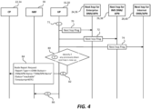
- FIG. 4 illustrates a control sequence identifying the status of a next hop that is back up and, in this example, comprises a control sequence that is sequential to that described above. Additionally, the system is similar that that described in connection with FIG. 3 and will not be redescribed here.
- step E the UP 16, 30 checks if the next hop that was down has now become available 71. This is accomplished by continuous sending of a ping 70 at a configurable interval towards the next hop.
- the UP 16, 30 identifies that a given next hop is now up 80. At this point, the UP 16, 30 will increment a KPI to count the time at which the Enterprise DNN / APN 24, 36 is now up.
- step G UP 16 30 notifies the CP 22, 34 that a given next hop that may have previously been down is now up 82. This can be done using PFCP update or any other proprietary mechanism 84 as described previously in connection with FIG. 3 .
- step H UP 16 30 updates the NRF 18 (if available in the network), that the given next hop is up 86. This can be done using HTTP, HTTPS or HTTP2 POST/PUT respectively or any other proprietary mechanism.
- next hop ping 70 identifying the Next hop for Enterprise DNN / APN 24, 36.
- next hop ping 72, 74 respectively, can be in connection with the Next hop for IMS DNN / APN 26, 38 or Next hop for internet DNN / APN 28, 40 based on the application as illustrated in FIG. 4 .
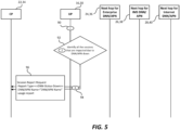
- step I UP 16 30 identifies the next hop that is down 90.
- step J UP 16 30 identifies all the sessions that are latched on to this DNN / APN next hop 92 (e.g., Enterprise DNN / APN 24, 36, IMS DNN / APN 26, 38, or internet DNN / APN 28, 40).
- this DNN / APN next hop 92 e.g., Enterprise DNN / APN 24, 36, IMS DNN / APN 26, 38, or internet DNN / APN 28, 40.
- step K UP 16 30 notifies the CP 22, 34 about the usage count for each of the session 94. It identifies the sessions that are not able to send the data due to non-availability of the next-hop 96. It also counts the usage for each of the sessions as they are not able to route the packets for the select APN/DNN.
Landscapes
- Engineering & Computer Science (AREA)
- Computer Networks & Wireless Communication (AREA)
- Signal Processing (AREA)
- Data Exchanges In Wide-Area Networks (AREA)
Abstract
A telecommunications system and method for identifying when a next hop is down by sending a first series of pings from a User Plane (UP) computer to the next hop, for incrementing a Key Performance Indicator (KPI) to count a time for when the next hop is down, and for communicating from the UP computer to a Control Plane (CP) computer that a next hop is down. The system facilitating identification of when the next hop transitions to up by sending a second series of pings from the UP computer to the next hop, for incrementing the KPI at the time when the next hop is up, and for communicating from the UP computer to the CP computer that the next hop is up.
Description
- The present disclosure is related to User Plane Function (UPF) that can be situated in a Radio Access Networks (RAN) or Core network where the Core network is referred to as an area outside the RAN and contains user plane entities. More particularly, the present disclosure is related to a system for identifying and quantifying data path failures at the User Plane (UP).
- 3rd Generation Partnership Project (3GPP) has a defined network architecture for 5G, where a User Plane Function (UPF) is connected via the N6 LAN to the Internet. User Equipment (UE) traffic is routed from the core network to the Internet using the N6 or Service Gateway interface (SGi) or another network. The N6 LAN is the portion of a 5G network that carries data from the UPF to the Internet. The SGi interface is defined by the 3GPP as the interface between the Evolved Packet Core (EPC) and the Public IP network. Traffic through the interface can be identified by user IP, making user and service differentiation possible.
- However, 3GPP does not define the action for notification by the User Plane (UP) User Plane Function or Serving / Packet Data Network Gateway User Plane Function (UPF or S/PGW-U) towards the Control Plane (CP) Sesson Management Function or Sesson / Packet Data Network Gateway Control Plane Function (SMF or S/PGW-C) when the N6 (or SGi) LAN is down. The PGW-U Gateway User plane function serves as the user data plane ingress and egress point to the EPC when control and user plane separation is in place.
- The 3GPP specifications have defined the procedures for selection of available UP by the CP for Protocol Data Unit (PDU) or Public Data Network (PDN) connection setup. However, while the UP may be available, the interface (N6 or SGi) towards the Data Network Name (DNN) or Access Point Name (APN) may be down, meaning it is not able to route the packets. This being the case, if the UP is not able to notify the CP regarding the available interface status of the N6 (5G) or SGi (4G), the CP will select the UP that is incapable of routing the UP packets. This negatively impacts the operator's success rate in making session setups, as the calls are not completed due to the unavailability of SGi or N6 LAN.
- Accordingly, a problem with current systems is that the CP can select a UP that does not have a currently functional N6/SGi-LAN connection.
- Accordingly, there is a need for a telecom system that overcomes, alleviates, and/or mitigates one or more of the aforementioned and other deleterious effects of prior art telecom systems where the CP selects a UP that does not have a functional connection.
- Accordingly, it would be advantageous to provide a telecom system that allows for the identification of the status of the next hop.
- It is further desired to provide a telecom system and method that allows for an operator to select a UP with a functional interface towards a DNN/APN respectively.
- It is also desired to provide a telecom system and method that allows for an operator to be able to define the Key Performance Indicators (KPIs) to count the downtime of the UP that has LANs, which are down.
- It is also desired to provide a telecom system and method that allows for an operator to be able to predictably count the packets for effective charging when the LAN goes down and the CP selects an alternate UP with working LAN.
- In current telecom systems, a situation may arise where a UP is connected to multiple SGi or N6 LAN next hops for different APN or DNN. At a given time, several next hops may be available, while several next hops are not available. Some next hops may be down for a few seconds, while others may be down for longer periods times. In such a case, the system and method according to one advantageous configuration provides for the UP to identify and quantify any N6 or SGi-LAN(s) that are currently down. This identification helps the operator to generate KPIs that count the duration for which the LAN is down and facilitates avoiding selection of the UPF. The KPI assists in identifying the revenue loss, due to the down time of LANs.
- This means that the system provides for predictable packet counting and charging when the LAN goes down during active user sessions. Additionally, it may be possible that the LAN is down while certain sessions are active on a given UP. In this case, the UP may pause the packet counting and inform the CP, so that the CP can select a new UP for the session continuity as well as for correct packet counting.
- Accordingly, in one configuration, the UP checks if the next hop is available. In one instance, this can be accomplished via ping at a configurable interval towards the next hop. The UP can then determine if the next hop is down. The UP can then notify the CP that the next hop is down. The UP may also update the NRF that the next hop is down.
- In another configuration, the UP checks if the next hop that was down is not available. This could be accomplished by sending a ping at a configurable interval towards the next hop. If the UP identifies that the next hop is up, the UP can then notify the CP that the next hop is up. The UP may also update the NRF that the next hop is up.
- In still another configuration, the UP checks if the next hop is down. The UP identifies all the sessions that are latched on this APN / DNN next hop. The UP may notify the CP about the usage count for each of the sessions and identify the sessions that are not able to send the data due to non-availability of next hop. The UP may further count the usage for each of the sessions not able to route the packets for the APN / DNN.
- The above-described functionality offers a pragmatic approach to notify the CP, about the DNN / APN that are down or up. This facilitates selecting the UP that currently has routable and available LAN services.
- The above-described functionality also provides for the UP to report the count of the usage of a given session to the CP until it has a routable SGi/N6 LAN interface. This helps the operator do appropriately count packets for a given UE. Additionally, this configuration allows the operator to count the time for which a given UPF is serviceable due to routable LAN.
- For this application the following terms and definitions shall apply:
The term "data" as used herein means any indicia, signals, marks, symbols, domains, symbol sets, representations, and any other physical form or forms representing information, whether permanent or temporary, whether visible, audible, acoustic, electric, magnetic, electromagnetic or otherwise manifested. The term "data" as used to represent predetermined information in one physical form shall be deemed to encompass any and all representations of the same predetermined information in a different physical form or forms. - The term "network" as used herein includes both networks and internetworks of all kinds, including the Internet, and is not limited to any particular type of network or inter-network.
- The terms "first" and "second" are used to distinguish one element, set, data, object or thing from another, and are not used to designate relative position or arrangement in time.
- The terms "coupled", "coupled to", "coupled with", "connected", "connected to", and "connected with" as used herein each mean a relationship between or among two or more devices, apparatus, files, programs, applications, media, components, networks, systems, subsystems, and/or means, constituting any one or more of (a) a connection, whether direct or through one or more other devices, apparatus, files, programs, applications, media, components, networks, systems, subsystems, or means, (b) a communications relationship, whether direct or through one or more other devices, apparatus, files, programs, applications, media, components, networks, systems, subsystems, or means, and/or (c) a functional relationship in which the operation of any one or more devices, apparatus, files, programs, applications, media, components, networks, systems, subsystems, or means depends, in whole or in part, on the operation of any one or more others thereof.
- The term "automatic" and variations thereof, as used herein, refers to any process or operation done without material human input when the process or operation is performed. However, a process or operation can be automatic, even though performance of the process or operation uses material or immaterial human input, if the input is received before performance of the process or operation. Human input is deemed to be material if such input influences how the process or operation will be performed. Human input that consents to the performance of the process or operation is not deemed to be "material."
- In one configuration, a telecommunications system for determining a status of a next hop in a Radio Access Networks (RAN) where User Equipment (UE) is wirelessly coupled to radio equipment is provided, the system comprising: a User Plane (UP) computer coupled to the radio equipment, a Control Plane (CP) computer, the CP computer coupled to the UP computer, and a plurality of next hops selectable by the UP computer for transmitting of data to and from the UE. The system is provided such that the UP computer transmits a first series of pings from the UP computer to one of the plurality of next hops, and the UP computer determines from the first series of pings whether the next hop the first series of pings was sent to is down. The system is further provided such that when the UP computer determines the next hop is down, the UP computer increments a Key Performance Indicator (KPI) to count a time period for when the next hops i down, and the UP computer notifying the CP computer that the next hop is down.
- The above-described and other features and advantages of the present disclosure will be appreciated and understood by those skilled in the art from the following detailed description, drawings, and appended claims.
-
-
FIG. 1 is a block diagram illustrating the 3GPP defined 5G network showing the position of the UPF; -
FIG. 2 is a block diagram illustrating the 3GPP defined 4G network showing the position of the UPF; -
FIG. 3 is a control diagram according to one of the configurations depicted inFIGS. 1 and2 where the system identifies if the next hop is down; -
FIG. 4 is a control diagram according to one of the configurations depicted inFIGS. 1 and2 where the system identifies if the next hop is up; and -
FIG. 5 is a control diagram according to one of the configurations depicted inFIGS. 1 and2 where the system reports the session count for impacted sessions. - Referring now to the drawings, wherein like reference numerals designate corresponding structure throughout the views.
- With reference to
FIGS. 1 and2 ,FIG. 1 illustrates a 3GPP defined 5G network showing the position of the User Plane Function (UPF), whileFIG. 2 illustrates a 3GPP defined 4G network showing the position of the UPF. - Referring to
FIG. 1 ,system 10 is illustrated in which User Equipment (UE) 12 is in contact withRadio 14, which in turn, is in contact with User Plane Function (UPF) 16 via GTPv1 connection. GTPV1 means the General Packet Radio Services (GPRS) Tunneling Protocol version 1 group of IP-based communications protocols used to carry GPRS within a Global System for Mobile communication (GSM) and Universal Mobile Telecommunications Systems (UMTS) networks. TheUPF 14 is connected to Network Repository Function (NRF) 18 via the nNRF connection. - The
Radio 14 is also connected via the N2 connection to Access and Mobility Management Function (AMF) 20, which is one of the control plane Network Functions (NF) of the 5G core network (5GC). It should be noted that the Radio Access Network (RAN) uses N2 (control plane) and N3 (user plane) to interface to the core and transparent N1 interface to the user devices. N1 is a transparent interface from 5G-UE to AMF of the core (via NG-RAN). The N1 interface is used by UE for transmitting non radio signaling between UE and AMF, which includes information related to connection, mobility and session related messages to the AMF, which handles cases related to connection, mobility messages, and forwards session management info to System Management Facility (SMF) 22. The N2 interface supports control plane signaling between RAN and 5G core covering scenarios related to UE context management, and PDU session/resource management procedures. N2 uses SCTP (NGAP) between 5GCN and access network. -
AMF 20 is connected toSMF 22 via the N11 connection.SMF 22 produces records of activity on a mainframe computer that are recorded to a file. Types of activities that may be recorded bySMF 22 include errors, software usage, network activity, and much more.UPF 16 is further connected toSMF 22 via the N4 connection. -
UPF 16 is then illustrated as variously connecting via the N6 connection to: Next hop for Enterprise Data Network Name (DNN) 24; to Next hop for IP Multimedia Subsystem (IMS)DNN 26; and to Next hop forinternet DNN 28. It should be noted that DNN is a unique identifier used by the 5G core network to route traffic to a specific network slice. - Referring now to
FIG. 2 , asystem 50 like that ofFIG. 1 is illustrated includingUE 12 connected toRadio 14, which is in turn, connected via GTPv1 to Packet Data Network Gateway User Plane (S/PGW-U) 30.Radio 14 is further connected to Mobility Management Entity (MME) 32 via the S1-MME connection, which is in turn, connected to Packet Data Network Gateway Control Plane (S/PGW-C) 34. Packet Data Network Gateway User Plane (S/PGW-U) 30 is connected to S/PGW-C 34 via the Sxa/Sxb connection. S/PGW-U 30 is variously connected via the SGi connection to: Next hop for Enterprise Access Point Name (APN) 36; to Next hop forIMS APN 38; and to Next hop forinternet APN 40. As stated above, it should be noted that DNN is a unique identifier used by the 5G core network to route traffic to a specific network slice. - Referring now to
FIGS. 3-5 , control diagrams according to advantageous configurations for the system inFIGS. 1 and2 are illustrated. - It should be noted that, while various functions and methods are described and presented in a sequence of steps, the sequence has been provided merely as an illustration of one advantageous embodiment, and that it is not necessary to perform these functions in the specific order illustrated. It is further contemplated that any of these steps may be moved and/or combined relative to any of the other steps. In addition, it is still further contemplated that it may be advantageous, depending upon the application, to utilize all or any portion of the functions described herein.
-
FIG. 3 illustrates a control sequence identifying the status of a next hop that is down.System 10 comprises a Control Plane (CP) 22, 34, a Network Repository Function (NRF) 18, and a User Plane (UP) 16, 30.FIG. 3 describes the process of determining the status of the next hop as a sequence of steps A - D described below. - At Step A the
UP ping 50 at a configurable interval towards the next hop. In this instance, the next hop is selected for Enterprise DNN /APN FIG. 1 orFIG. 2 is used. - At step B after iterating for the configurable time, the
UP UP APN - At step C the
UP CP proprietary mechanism 64. A PFCP is a 3GPP protocol used on the Sx/N4 interface between theCP UP - At step D the
UP NRF 18, if available in the network that the given next hop is down 66. This can be done using HTTP, HTTPS or HTTP2 POST/PUT respectively or any other proprietary mechanism. - It will be noted that the above was described in connection with using the
next hop ping 50 identifying the Next hop for Enterprise DNN /APN FIG. 3 thenext hop ping APN APN -
FIG. 4 illustrates a control sequence identifying the status of a next hop that is back up and, in this example, comprises a control sequence that is sequential to that described above. Additionally, the system is similar that that described in connection withFIG. 3 and will not be redescribed here. - At step E the
UP ping 70 at a configurable interval towards the next hop. - At step F after iterating for the configurable time, the
UP UP APN - At
step G UP CP proprietary mechanism 84 as described previously in connection withFIG. 3 . - At
step H UP - As described in connection with
FIG. 3 , the above was described in connection with using thenext hop ping 70 identifying the Next hop for Enterprise DNN /APN next hop ping APN APN FIG. 4 . - Referring now to
FIG. 5 , the counting of the usage report for impacted sessions is described. - At step I UP 16, 30 identifies the next hop that is down 90.
- At
step J UP APN APN APN 28, 40). - At
step K UP CP session 94. It identifies the sessions that are not able to send the data due to non-availability of the next-hop 96. It also counts the usage for each of the sessions as they are not able to route the packets for the select APN/DNN. - While the present disclosure has been described with reference to one or more exemplary embodiments, it will be understood by those skilled in the art that various changes may be made and equivalents may be substituted for elements thereof without departing from the scope of the present disclosure. In addition, many modifications may be made to adapt a particular situation or material to the teachings of the disclosure without departing from the scope thereof. Therefore, it is intended that the present disclosure not be limited to the particular embodiment(s) disclosed as the best mode contemplated, but that the disclosure will include all embodiments falling within the scope of the appended claims.
Claims (15)
- A telecommunications system for determining a status of a next hop in a Radio Access Networks (RAN) where User Equipment (UE) is wirelessly coupled to radio equipment, the system comprising:a User Plane (UP) computer coupled to the radio equipment;a Control Plane (CP) computer, said CP computer coupled to said UP computer; anda plurality of next hops selectable by said UP computer for transmitting of data to and from the UE;said UP computer transmitting a first series of pings from said UP computer to one of the plurality of next hops;said UP computer determining from the first series of pings whether the next hop the first series of pings was sent to is down;wherein when said UP computer determines the next hop is down, said UP computer increments a Key Performance Indicator (KPI) to count a time period for when the next hop is down;said UP computer notifying said CP computer that the next hop is down.
- The telecommunications system according to claim 1, wherein the first series of pings is continuous for a first period of time.
- The telecommunications system according to claim 2, wherein the first period of time is configurable.
- The telecommunications system according to claim 1, wherein said UP computer notifies said CP computer that next hop is down via a Packet Forwarding Control Protocol (PFCP) mechanism.
- The telecommunications system according to claim 1, further comprising:a Network Repository Function (NRF) coupled to said UP computer;wherein said UP computer updates said NRF that the next hop is down.
- The telecommunications system according to claim 5, wherein said UP computer updates said NRF via HTTP, HTTPS or HTTP2 POST/PUT.
- The telecommunications system according to claim 1, wherein the one of the plurality of next hops is selected from the group consisting of:an enterprise Data Network Name (DNN) or Access Point Name (APN);an IP multimedia subsystem DNN or APN; oran internet DNN or APN.
- The telecommunications system according to claim 1, wherein when said UP computer identifies that the one of the plurality of next hops is down, said UP computer identifies all sessions that are latched onto the next hop that is down and notifies said CP computer about a usage count for each of the identified sessions.
- The telecommunications system according to claim 8, wherein said UP computer identifies failed sessions that are not able to send data due to non-availability of the next hop that is down and counts a usage for each session not able to route packets.
- The telecommunications system according to claim 9, wherein said UP computer reports the usage count of a given session to the CP computer until it has a routable SGi/N6 LAN interface.
- The telecommunications system according to claim 1, wherein,said UP computer transmits a second series of pings from said UP computer to the next hop that was previously determined to be down;said UP computer determining from the second series of pings whether the next hop that was down is now up;wherein when said UP computer determines the next hop is up, said UP computer increments the KPI to count a time period at which the next hop is now up;said UP computer notifying said CP computer that the next hop is up.
- The telecommunications system according to claim 11, wherein said UP computer notifies said CP computer that the next hop is up via a Packet Forwarding Control Protocol (PFCP) mechanism.
- The telecommunications system according to claim 11, further comprising:a Network Repository Function (NRF) coupled to said UP computer;wherein said UP computer updates said NRF that the next hop is up.
- The telecommunications system according to claim 11, wherein the second series of pings is continuous for a second period of time.
- The telecommunications system according to claim 14, wherein the second period of time is configurable.
Applications Claiming Priority (2)
| Application Number | Priority Date | Filing Date | Title |
|---|---|---|---|
| IN202321085843 | 2023-12-15 | ||
| US18/971,275 US20250202798A1 (en) | 2023-12-15 | 2024-12-06 | Method and Apparatus to handle Partial Data Path Failure at User Plane |
Publications (1)
| Publication Number | Publication Date |
|---|---|
| EP4572286A1 true EP4572286A1 (en) | 2025-06-18 |
Family
ID=93893591
Family Applications (1)
| Application Number | Title | Priority Date | Filing Date |
|---|---|---|---|
| EP24218935.5A Pending EP4572286A1 (en) | 2023-12-15 | 2024-12-11 | Method and apparatus to handle partial data path failure at user plane |
Country Status (1)
| Country | Link |
|---|---|
| EP (1) | EP4572286A1 (en) |
Citations (2)
| Publication number | Priority date | Publication date | Assignee | Title |
|---|---|---|---|---|
| US10638400B1 (en) * | 2018-10-24 | 2020-04-28 | Syniverse Technologies, Llc | Systems and methods of optimal wireless traffic routing |
| US20220183098A1 (en) * | 2019-03-08 | 2022-06-09 | Telefonaktiebolaget Lm Ericsson (Publ) | Method and Apparatus for User Plane Path Failure and Recovery Handling |
-
2024
- 2024-12-11 EP EP24218935.5A patent/EP4572286A1/en active Pending
Patent Citations (2)
| Publication number | Priority date | Publication date | Assignee | Title |
|---|---|---|---|---|
| US10638400B1 (en) * | 2018-10-24 | 2020-04-28 | Syniverse Technologies, Llc | Systems and methods of optimal wireless traffic routing |
| US20220183098A1 (en) * | 2019-03-08 | 2022-06-09 | Telefonaktiebolaget Lm Ericsson (Publ) | Method and Apparatus for User Plane Path Failure and Recovery Handling |
Non-Patent Citations (1)
| Title |
|---|
| CISCO: "Ultra Cloud Core 5G User Plane Function, Release 2021.01 - Configuration and Administration Guide", 29 January 2021 (2021-01-29), pages 1 - 234, XP093241580, Retrieved from the Internet <URL:www.cisco.com> [retrieved on 20210129] * |
Similar Documents
| Publication | Publication Date | Title |
|---|---|---|
| US9686774B2 (en) | Communication system, method, and apparatus | |
| CN113630794B (en) | Measurement in a multimedia broadcast multicast service | |
| US20160192263A1 (en) | Communication system, method, and apparatus | |
| US8867471B2 (en) | Method, device, and system for reporting radio access network element information | |
| US8755352B2 (en) | Method and apparatus for deferred leg linking in PCRF in relation to handover | |
| JP2012249288A (en) | Network monitoring system and computer readable recording medium | |
| CN101547168B (en) | Device reset notification method and system, service and packet data gateway and mobile management network element | |
| CN102752709A (en) | Methods and devices for processing network load information, user position information and policy | |
| CN101631344B (en) | Tunnel management method, device and communication system | |
| KR20110002835A (en) | Method for updating location information of user equipment | |
| US20090175201A1 (en) | Method and apparatus for configuring link parameter thresholds | |
| US8934861B2 (en) | Technique for monitoring a call | |
| JP2010516072A (en) | Mechanism for uniquely identifying and unifying packet bearer context user sets in mobile communication networks | |
| CN117939552A (en) | Call method, device and storage medium | |
| JPWO2010004714A1 (en) | Handover processing method, mobile terminal and communication management apparatus used in the method | |
| CN113169884A (en) | Removing application identifiers | |
| US20250202798A1 (en) | Method and Apparatus to handle Partial Data Path Failure at User Plane | |
| EP2941916B1 (en) | Tracing inter-rat events | |
| US20110256856A1 (en) | UE Detach | |
| US9609551B2 (en) | Charging information accuracy in a telecommunications network | |
| JPWO2007043117A1 (en) | Mobile communication system, mobile communication terminal and call connection method | |
| CN100417102C (en) | System and method for monitoring service quality | |
| US20250212077A1 (en) | Method & Apparatus for Targeted AMF Offload | |
| EP4576851A1 (en) | Method for targeted amf offload | |
| CN104796941A (en) | Congestion control method in case of access core network via TWAN (Trusted WLAN access network) and device |
Legal Events
| Date | Code | Title | Description |
|---|---|---|---|
| PUAI | Public reference made under article 153(3) epc to a published international application that has entered the european phase |
Free format text: ORIGINAL CODE: 0009012 |
|
| STAA | Information on the status of an ep patent application or granted ep patent |
Free format text: STATUS: REQUEST FOR EXAMINATION WAS MADE |
|
| 17P | Request for examination filed |
Effective date: 20241211 |
|
| AK | Designated contracting states |
Kind code of ref document: A1 Designated state(s): AL AT BE BG CH CY CZ DE DK EE ES FI FR GB GR HR HU IE IS IT LI LT LU LV MC ME MK MT NL NO PL PT RO RS SE SI SK SM TR |
|
| STAA | Information on the status of an ep patent application or granted ep patent |
Free format text: STATUS: THE APPLICATION IS DEEMED TO BE WITHDRAWN |