EP4572276A1 - Data transmission method, and device and storage medium - Google Patents
Data transmission method, and device and storage medium Download PDFInfo
- Publication number
- EP4572276A1 EP4572276A1 EP23861945.6A EP23861945A EP4572276A1 EP 4572276 A1 EP4572276 A1 EP 4572276A1 EP 23861945 A EP23861945 A EP 23861945A EP 4572276 A1 EP4572276 A1 EP 4572276A1
- Authority
- EP
- European Patent Office
- Prior art keywords
- data sequence
- data
- sequence
- raised cosine
- cosine function
- Prior art date
- Legal status (The legal status is an assumption and is not a legal conclusion. Google has not performed a legal analysis and makes no representation as to the accuracy of the status listed.)
- Pending
Links
Images


Classifications
-
- H—ELECTRICITY
- H04—ELECTRIC COMMUNICATION TECHNIQUE
- H04L—TRANSMISSION OF DIGITAL INFORMATION, e.g. TELEGRAPHIC COMMUNICATION
- H04L27/00—Modulated-carrier systems
- H04L27/26—Systems using multi-frequency codes
-
- H—ELECTRICITY
- H04—ELECTRIC COMMUNICATION TECHNIQUE
- H04L—TRANSMISSION OF DIGITAL INFORMATION, e.g. TELEGRAPHIC COMMUNICATION
- H04L27/00—Modulated-carrier systems
- H04L27/18—Phase-modulated carrier systems, i.e. using phase-shift keying
- H04L27/20—Modulator circuits; Transmitter circuits
- H04L27/2032—Modulator circuits; Transmitter circuits for discrete phase modulation, e.g. in which the phase of the carrier is modulated in a nominally instantaneous manner
- H04L27/2035—Modulator circuits; Transmitter circuits for discrete phase modulation, e.g. in which the phase of the carrier is modulated in a nominally instantaneous manner using a single or unspecified number of carriers
-
- H—ELECTRICITY
- H04—ELECTRIC COMMUNICATION TECHNIQUE
- H04L—TRANSMISSION OF DIGITAL INFORMATION, e.g. TELEGRAPHIC COMMUNICATION
- H04L27/00—Modulated-carrier systems
- H04L27/18—Phase-modulated carrier systems, i.e. using phase-shift keying
- H04L27/20—Modulator circuits; Transmitter circuits
- H04L27/2032—Modulator circuits; Transmitter circuits for discrete phase modulation, e.g. in which the phase of the carrier is modulated in a nominally instantaneous manner
- H04L27/2053—Modulator circuits; Transmitter circuits for discrete phase modulation, e.g. in which the phase of the carrier is modulated in a nominally instantaneous manner using more than one carrier, e.g. carriers with different phases
-
- H—ELECTRICITY
- H04—ELECTRIC COMMUNICATION TECHNIQUE
- H04L—TRANSMISSION OF DIGITAL INFORMATION, e.g. TELEGRAPHIC COMMUNICATION
- H04L27/00—Modulated-carrier systems
- H04L27/26—Systems using multi-frequency codes
- H04L27/2601—Multicarrier modulation systems
- H04L27/2614—Peak power aspects
-
- H—ELECTRICITY
- H04—ELECTRIC COMMUNICATION TECHNIQUE
- H04L—TRANSMISSION OF DIGITAL INFORMATION, e.g. TELEGRAPHIC COMMUNICATION
- H04L27/00—Modulated-carrier systems
- H04L27/26—Systems using multi-frequency codes
- H04L27/2601—Multicarrier modulation systems
- H04L27/2626—Arrangements specific to the transmitter only
-
- H—ELECTRICITY
- H04—ELECTRIC COMMUNICATION TECHNIQUE
- H04L—TRANSMISSION OF DIGITAL INFORMATION, e.g. TELEGRAPHIC COMMUNICATION
- H04L27/00—Modulated-carrier systems
- H04L27/26—Systems using multi-frequency codes
- H04L27/2601—Multicarrier modulation systems
- H04L27/2626—Arrangements specific to the transmitter only
- H04L27/2627—Modulators
- H04L27/2628—Inverse Fourier transform modulators, e.g. inverse fast Fourier transform [IFFT] or inverse discrete Fourier transform [IDFT] modulators
-
- H—ELECTRICITY
- H04—ELECTRIC COMMUNICATION TECHNIQUE
- H04L—TRANSMISSION OF DIGITAL INFORMATION, e.g. TELEGRAPHIC COMMUNICATION
- H04L27/00—Modulated-carrier systems
- H04L27/26—Systems using multi-frequency codes
- H04L27/2601—Multicarrier modulation systems
- H04L27/2626—Arrangements specific to the transmitter only
- H04L27/2627—Modulators
- H04L27/2634—Inverse fast Fourier transform [IFFT] or inverse discrete Fourier transform [IDFT] modulators in combination with other circuits for modulation
- H04L27/2636—Inverse fast Fourier transform [IFFT] or inverse discrete Fourier transform [IDFT] modulators in combination with other circuits for modulation with FFT or DFT modulators, e.g. standard single-carrier frequency-division multiple access [SC-FDMA] transmitter or DFT spread orthogonal frequency division multiplexing [DFT-SOFDM]
-
- H—ELECTRICITY
- H04—ELECTRIC COMMUNICATION TECHNIQUE
- H04L—TRANSMISSION OF DIGITAL INFORMATION, e.g. TELEGRAPHIC COMMUNICATION
- H04L5/00—Arrangements affording multiple use of the transmission path
- H04L5/0001—Arrangements for dividing the transmission path
- H04L5/0003—Two-dimensional division
- H04L5/0005—Time-frequency
- H04L5/0007—Time-frequency the frequencies being orthogonal, e.g. OFDM(A) or DMT
-
- H—ELECTRICITY
- H04—ELECTRIC COMMUNICATION TECHNIQUE
- H04L—TRANSMISSION OF DIGITAL INFORMATION, e.g. TELEGRAPHIC COMMUNICATION
- H04L5/00—Arrangements affording multiple use of the transmission path
- H04L5/003—Arrangements for allocating sub-channels of the transmission path
- H04L5/0044—Allocation of payload; Allocation of data channels, e.g. PDSCH or PUSCH
Definitions
- the present application relates to the field of wireless communications, for example, a data transmission method and device and a storage medium.
- frequency bands can be divided into high-frequency bands and low-frequency bands.
- High-frequency bands are millimeter-wave bands while low-frequency bands overlap the frequency bands used in the fourth-generation (4G) mobile communication technology.
- Low-frequency bands are primarily used for Massive Machine-Type Communications (mMTC) services while high-frequency bands are primarily used for enhanced Mobile BroadBand (eMBB) services and Ultra-Reliable Low-Latency Communications (URLLC) services.
- mMTC Massive Machine-Type Communications
- eMBB enhanced Mobile BroadBand
- URLLC Ultra-Reliable Low-Latency Communications
- High-frequency bands experience significant path loss and shadow fading, resulting in very low signal-to-noise ratios (SNR) in certain areas at the cell edge. Additionally, in high-frequency scenarios, the efficiency of a power amplifier (PA) is relatively low. To improve the signal-to-interference-plus-noise ratio (SINR) while conserving battery power for a user equipment (UE), it is necessary for the peak-to-average power ratio (PAPR) of the signals transmitted by the UE to be kept low.
- SINR signal-to-interference-plus-noise ratio
- PAPR peak-to-average power ratio
- MCS modulation and coding scheme
- DFT-s-OFDM discrete Fourier transform-spread-orthogonal frequency-division multiplexing
- Embodiments of the present application provide a data transmission method and device and a storage medium.
- an embodiment of the present application provides a data transmission method.
- the method includes performing a pointwise multiplication between a first data sequence and a second data sequence to obtain a third data sequence, where the first data sequence and the second data sequence are each a frequency-domain data sequence; performing an inverse Fourier transform on the third data sequence to obtain a fourth data sequence; and transmitting the fourth data sequence on a physical time-frequency resource.
- an embodiment of the present application provides a data transmission device.
- the device includes a memory configured to store a program; and a processor configured to execute the program to perform a pointwise multiplication between a first data sequence and a second data sequence to obtain a third data sequence, where the first data sequence and the second data sequence are each a frequency-domain data sequence; perform an inverse Fourier transform on the third data sequence to obtain a fourth data sequence; and transmit the fourth data sequence on a physical time-frequency resource.
- an embodiment of the present application provides a storage medium.
- the storage medium stores a program.
- the program is executed, the data transmission method of any embodiment of the present application is performed.
- the data transmission method and device and the storage medium involve performing an inverse Fourier transform on a data sequence generated by pointwise multiplication between two frequency-domain data sequences; and then transmitting the data sequence after the inverse Fourier transform on a physical time-frequency resource, thereby effectively reducing the PAPR of the transmitted data sequence.
- FIG. 1 is a flowchart of a data transmission method according to an embodiment of the present application. As shown in FIG. 1 , the data transmission method of this embodiment includes S110 to S130.
- pointwise multiplication is performed between a first data sequence and a second data sequence to obtain a third data sequence, where the first data sequence and the second data sequence are each a frequency-domain data sequence.
- the data transmission method of this embodiment can be applied to any node in a wireless communication system, particularly a user equipment (UE) in this system.
- UE user equipment
- this embodiment of the present application provides a signal modulation scheme. Modulation using this signal modulation scheme before transmission enables a lower PAPR.
- pointwise multiplication is performed between a first data sequence and a second data sequence to obtain a third data sequence.
- the first data sequence is a to-be-transmitted data sequence while the second data sequence is a preset data sequence.
- the first data sequence and the second data sequence are each a frequency-domain data sequence.
- Pointwise multiplication between the first data sequence and the second data sequence can also be referred to as frequency-domain shaping of the first data sequence, with the second data sequence as the frequency-domain shaping function.
- the pointwise multiplication can also be referred to as a filtering operation, with the second data sequence as the filtering function.
- the first data sequence is denoted as [ X ( j )]
- the second data sequence is denoted as [ Z ( j )]
- the third data sequence is denoted as [ S ( j )].
- ⁇ denotes multiplication.
- the length of the first data sequence and the length of the second data sequence may be the same or different. That is, the length J of the first data sequence [ X ( j )] and the length J of the second data sequence [ Z ( j )] may be the same or different.
- the second data sequence may be generated using a root-raised cosine function.
- the root-raised cosine function is a frequency-domain compressed root-raised cosine function.
- the value range of the roll-off factor of the root-raised cosine function is [0.7, 1].
- the ratio of the half-power bandwidth of the root-raised cosine function to the bandwidth occupied by the first data sequence is P/2.
- the value range of P is [0.9, 1.1].
- the roll-off factor of the root-raised cosine function is 1.
- the second data sequence is generated by discrete sampling on the root-raised cosine function.
- the length of the independent variable corresponding to a non-zero function value of the root-raised cosine function is less than or equal to the bandwidth occupied by the first data sequence.
- the root-raised cosine function sry f y f .
- A denotes a constant
- ⁇ denotes the roll-off factor of the root-raised cosine function
- 2 f 0 denotes the half-power bandwidth of the root-raised cosine function
- 2 f 0 (1 + ⁇ ) denotes the length of the independent variable corresponding to a non-zero function value of the root-raised cosine function.
- the first data sequence is generated from a fifth data sequence by a Fourier transform.
- the fifth data sequence is a time-domain data sequence.
- the fifth data sequence is generated from a sixth data sequence.
- the sixth data sequence is formed by constellation modulation of a seventh data sequence composed of 0 and 1. Constellation modulation of the sixth data sequence is ⁇ /2-binary phase-shift keying ( ⁇ /2-BPSK).
- the sixth data sequence is a reference sequence.
- the constellation modulation of the reference sequence is ⁇ /2-BPSK.
- the sixth data sequence contains L pieces of reference sequence data as well as constellation-modulated data. L ⁇ 0.
- the fifth data sequence is denoted as [ x ( j )]
- the sixth data sequence is denoted as [ d ( i )]
- the seventh data sequence is denoted as [ b ( m )].
- the fifth data sequence is generated from the sixth data sequence in the following manner: N pieces of new data are inserted between each two adjacent pieces of data in the sixth data sequence.
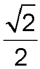
- each of the N pieces of new data is the sum of the two adjacent pieces of data multiplied by 2 2
- N is a non-negative integer.
- N is 0 or 1.
- the sixth data sequence is used as the fifth data sequence.
- the value of N is 1, one piece of new data is inserted between each two adjacent pieces of data in the sixth data sequence, and the new piece of data is the sum of the two adjacent pieces of data multiplied by 2 2 .
- the fifth data sequence is generated from the sixth data sequence in the following manner: N pieces of new data are inserted between each two adjacent pieces of data in the sixth data sequence.
- the magnitude of each of the N pieces of new data is the same as the magnitude of each of the two adjacent pieces of data
- the phase difference between adjacent pieces of data in the sixth data sequence obtained after the N pieces of new data are inserted is ⁇ 2 N + 2
- N is a non-negative integer.
- Each piece of data in a data sequence has the same magnitude.
- the phase difference between adjacent pieces of data after the insertion is ⁇ 2 N + 2 .
- the phase difference between adjacent pieces of data decreases, resulting in a lower PAPR for the time-domain data.
- an inverse Fourier transform is performed on the third data sequence to generate a fourth data sequence.
- it is feasible to perform the inverse Fourier transform on the third data sequence meaning that oversampling is not required. Additionally, when oversampling is required, it is feasible to perform a zero-padding operation on the third data sequence to form a new data sequence and then perform the inverse Fourier transform on the new data sequence to generate the fourth data sequence.
- the fourth data sequence is denoted as [ s ( k )].
- k 1,2,..., K .
- the fourth data sequence is, for example, [ s ( k )], and J ⁇ K .
- k 1,2,..., K .
- the fourth data sequence is transmitted on a physical time-frequency resource.
- the fourth data sequence can be transmitted on a physical time-frequency resource. This effectively reduces the PAPR of the transmitted fourth data sequence.
- the reason for this is that frequency-domain pointwise multiplication is equivalent to time-domain data convolution.
- a predesigned weight coefficient sequence forms the time-domain discrete data of a well-designed frequency-domain data sequence.
- the correlation between adjacent data improves, thereby effectively reducing the PAPR of the transmitted data sequence.
- the frequency-domain data sequence corresponding to this set of discrete time-domain data is generated using a root-raised cosine function, the data correlation is better optimized.
- the data transmission method of this embodiment of the present application involves performing an inverse Fourier transform on a data sequence generated by pointwise multiplication between two frequency-domain data sequences; and then transmitting the data sequence after the inverse Fourier transform on a physical time-frequency resource, thereby effectively reducing the PAPR of the transmitted data sequence.
- the fifth data sequence is ⁇ /2-BPSK modulated data that has a relatively low PAPR.
- N the value of N
- one piece of data is inserted between each two adjacent pieces of data in the sixth data sequence.
- the phase difference between the two adjacent pieces of data becomes ⁇ /4 from ⁇ /2 after the data insertion. This reduces the PAPR of the transmitted data sequence, resulting in a lower PAPR than that in ⁇ /2-BPSK constellation modulation.
- the half-power bandwidth of the root-raised cosine function is half of the bandwidth occupied by the first data sequence.
- the roll-off factor of the root-raised cosine function is 1. The advantage is that no additional frequency-domain bandwidth is occupied, the transmitted data sequence has a low PAPR, and demodulation at the receiving end is not affected. This is because when the roll-off factor of the root-raised cosine function is 1, the bandwidth of the root-raised cosine function is the same as the bandwidth occupied by the first data sequence, indicating a compression rate of 50% in the frequency domain.
- the time-domain data are either ⁇ /2-BPSK constellation-modulated data or interpolated from such data.
- the adjacent data are located on different directional axes, ensuring that the demodulation at the receiving end remains unaffected.
- the sixth data sequence is a reference sequence.
- the constellation modulation of the reference sequence is ⁇ /2-BPSK.
- the reference sequence also has a low PAPR, and when the value of N is 1, this reference sequence is used for channel estimation, resulting in a better performance at the receiving end.
- the second data sequence may be generated using a raised cosine function.
- the raised cosine function is a frequency-domain compressed raised cosine function.
- the value range of the roll-off factor of the raised cosine function is [0.7, 1].
- the ratio of the half-power bandwidth of the raised cosine function to the bandwidth occupied by the first data sequence is P/2.
- the value range of P is [0.9, 1.1].
- the roll-off factor of the raised cosine function is 1.
- the second data sequence is generated by discrete sampling on the raised cosine function.
- the length of the independent variable corresponding to a non-zero function value of the raised cosine function is less than or equal to the bandwidth occupied by the first data sequence.
- A denotes a constant
- ⁇ denotes the roll-off factor of the raised cosine function
- 2 f 0 denotes the half-power bandwidth of the raised cosine function
- 2 f 0 (1 + ⁇ ) denotes the length of the independent variable corresponding to a non-zero function value of the raised cosine function.
- the frequency-domain data sequence [ X ( j )] [ x (1), x (2), ..., x ( J )].
- the predefined frequency-domain data sequence[ Z ( j )] [ z (1), z (2), ..., z ( J )].
- the frequency-domain data sequence [ X ( j )] is pointwise-multiplied by the predefined frequency-domain data sequence [ Z ( j )] to form the data sequence [ S ( j )].
- the data sequence[ S ( j )] is expressed as follows:
- [ S ( j )] [ x (1) ⁇ z (1), x (2) ⁇ z (2), ⁇ , x ( J ) ⁇ z ( J )].
- ⁇ denotes multiplication.
- the data sequence [ S ( j )] experiences an inverse Fourier transform to form the data sequence [ s ( k )].
- the data sequence [ s ( k )] is transmitted on a physical time-frequency resource.
- the frequency-domain data sequence [ X ( j )] is pointwise-multiplied by the predefined frequency-domain data sequence [ Z ( j )] to form the data sequence [ S ( j )].
- the frequency-domain data sequence [ X ( j )] is formed from the time-domain data sequence [ x ( j )] by a Fourier transform.
- the time-domain data sequence [ x ( j )] is generated from the data sequence [ d ( i )].
- the constellation modulation of the data sequence [ d ( i )] is ⁇ /2-BPSK.
- the data sequence [ d ( i )] is the data sequence [ X ( j )].
- the data sequence [ d ( i )] is the data sequence [ x ( j )]
- the frequency-domain data sequence [ X ( j )] is pointwise-multiplied by the predefined frequency-domain data sequence [ Z ( j )] to form the data sequence [ S ( j )].
- the frequency-domain data sequence [ X ( j )] is formed from the time-domain data sequence [ x ( j )] by a Fourier transform.
- the time-domain data sequence [ x ( j )] is generated from the data sequence [ d ( i )].
- the constellation modulation of the data sequence [ d ( i )] is ⁇ /2-BPSK.
- One piece of data is inserted between each two adjacent pieces of data in the data sequence [ d ( i )], and the inserted piece of data is the sum of the two adjacent pieces of data multiplied by 2 2 . Then the time-domain reference sequence [ x ( j )] is formed.
- the frequency-domain data sequence [ X ( j )] is pointwise-multiplied by the predefined frequency-domain data sequence [ Z ( j )] to form the data sequence [ S ( j )].
- the frequency-domain data sequence [ X ( j )] is formed from the time-domain data sequence [ x ( j )] by a Fourier transform.
- the time-domain data sequence [ x ( j )] is generated from the data sequence [ d ( j )] .
- N pieces of data are inserted between each two adjacent pieces of data in the data sequence [ d ( i )] .
- Each of the N pieces of data is the sum of the two adjacent pieces of data multiplied by 2 2 .
- the time-domain data sequence [ x ( j )] is formed.
- N 0 or 1.
- the constellation modulation of the data sequence [ d ( i )] is ⁇ /2-BPSK.
- N pieces of data are inserted between each two adjacent pieces of data in the data sequence [ d ( i )].
- the value of N is 0. That is, no data is inserted between each two adjacent pieces of data in the data sequence [ d ( i )].
- the data sequence [ d ( i )] is the data sequence [ x ( j )].
- the frequency-domain data sequence [ X ( j )] is pointwise-multiplied by the predefined frequency-domain data sequence [ Z ( j )] to form the data sequence [ S ( j )].
- the frequency-domain data sequence [ X ( j )] is formed from the time-domain data sequence [ X ( j )] by a Fourier transform.
- the time-domain data sequence [ x ( j )] is generated from the data sequence [ d ( i )].
- N pieces of data are inserted between each two adjacent pieces of data in the data sequence [ d ( i )].
- Each of the N pieces of data is the sum of the two adj acent pieces of data multiplied by 2 2 .
- the time-domain data sequence[ x ( j )] is formed.
- N 0 or 1.
- the constellation modulation of the data sequence [ d ( i )] is ⁇ /2-BPSK.
- N pieces of data are inserted between each two adjacent pieces of data in the data sequence [ d ( i )].
- the value of N is 1. That is, one piece of data is inserted between each two adjacent pieces of data in the data sequence [ d ( i )], and the inserted piece of data is the sum of the two adjacent pieces of data multiplied by 2 2 .
- the time-domain reference sequence [ x ( j )] is formed.
- One piece of data is inserted between the data sequence d ( 0) and the data sequence d (1) to form the time-domain data sequence x ( 1).
- One piece of data is inserted between the data sequence d ( 2) and the data sequence d ( 3) to form the time-domain data sequence x ( 5).
- One piece of data is inserted between the data sequence d ( 3) and the data sequence d ( 4) to form the time-domain data sequence x ( 7).
- the frequency-domain data sequence [ X ( j )] is pointwise-multiplied by the predefined frequency-domain data sequence [ Z ( j )] to form the data sequence [ S ( j )].
- the frequency-domain data sequence [ X ( j )] is formed from the time-domain data sequence [ x ( j )] by a Fourier transform.
- the time-domain data sequence [ x ( j )] is generated from the data sequence [ d ( i )].
- N pieces of data are inserted between each two adjacent pieces of data in the data sequence [ d ( i )].
- the magnitude of each of the inserted N pieces of data is the same as the magnitude of each of the two adjacent pieces of data.
- the phase difference between adjacent pieces of data obtained after the N pieces of data are inserted is ⁇ 2 N + 2 .
- N is a non-negative integer.
- the constellation modulation of the data sequence [ d ( i )] is ⁇ /2-BPSK.
- N pieces of data are inserted between each two adjacent pieces of data in the data sequence [ d ( i )].
- the magnitude of each of the inserted N pieces of data is the same as the magnitude of each of the two adjacent pieces of data.
- the phase difference between adjacent pieces of data obtained after the N pieces of data are inserted is ⁇ 2 N + 2 .
- N is a non-negative integer.
- the data sequence [ d ( i )] is the data sequence [ x ( j )]
- the constellation modulation of the data sequence [ d ( i )] is ⁇ /2-BPSK
- the constellation modulation of the data sequence [ x ( j )] is also ⁇ /2-BPSK.
- the data sequence [ x ( j )] has the same magnitude.
- the value of N is 1, that is, one piece of data is inserted between each two adjacent pieces of data in the data sequence [ d ( i )].
- FIG. 2 is a diagram illustrating the insertion of one piece of data between two adjacent pieces of data.
- the horizontal axis represents the real part of the data
- the vertical axis represents the imaginary part of the data.
- the data sequence d ( 0) is the time-domain data sequence x( 0).
- One piece of data is inserted between the data sequence d ( 0) and the data sequence d ( 1) to form the time-domain data sequence x ( 1).
- the data sequence d ( 1) is the time-domain data sequence x ( 2).
- One piece of data is inserted between the data sequence d ( 1) and the data sequence d ( 2) to form the time-domain data sequence x ( 3).
- the data sequence d ( 2) is the time-domain data sequence x ( 4).
- One piece of data is inserted between the data sequence d ( 2) and the data sequence d ( 3) to form the time-domain data sequence x ( 5).
- the data sequence d ( 3) is the time-domain data sequence x ( 6).
- One piece of data is inserted between the data sequence d ( 3) and the data sequence d ( 4) to form the time-domain data sequence x ( 7).
- the data sequence d ( 4) is the time-domain data sequence x ( 8).
- the data sequence [ x ( j )] has magnitudes [1, 1, 1, 1, 1, 1, 1, 1].
- the magnitude of each of the inserted pieces of data [ x ( 1) , x ( 3) , x ( 5) , x ( 7)] is the same as the magnitude of each of the two adjacent pieces of data [ x ( 0) x ( 2) , x ( 2) x ( 4) , x ( 4) x ( 6), x ( 6) x ( 8)] x ( 0) , x (1) , x (2) , x ( 3) , x (4) , x ( 5) , x ( 6) , x ( 7) , x ( 8) has phases 0 , ⁇ 4 , ⁇ 2 , 3 ⁇ 4 , ⁇ , 5 ⁇ 4 , 3 ⁇ 2 , 7 ⁇ 4 , 2 ⁇ .
- phase difference between the inserted data [ x ( 1) , x ( 3) , x ( 5) , x ( 7) and two adjacent pieces of data [ x ( 0) x ( 2) , x ( 2) x ( 4) , x ( 4) x ( 6) , x ( 6) x ( 8)] is ⁇ 4 .
- FIG. 3 is a diagram illustrating the insertion of two pieces of data between two adjacent pieces of data.
- the data sequence d ( 0) is the time-domain data sequence x ( 0).
- Two pieces of data which are inserted between the data sequence d ( 0) and the data sequence d (1) are two time-domain data sequences x ( 1) and x ( 2).
- the data sequence d ( 1) is the time-domain data sequence x (3).
- Two pieces of data which are inserted between the data sequence d ( 1) and the data sequence d ( 2) are two time-domain data sequences x (4) and x ( 5).
- the data sequence d ( 2) is the time-domain data sequence x ( 6).
- Two pieces of data which are inserted between the data sequence d ( 2) and the data sequence d ( 3) are two time-domain data sequences x ( 7) and x ( 8).
- the data sequence d ( 3) is the time-domain data sequence x ( 9).
- Two pieces of data which are inserted between the data sequence d ( 3) and the data sequence d ( 4) are two time-domain data sequences x ( 10) and x ( 11).
- the data sequence d ( 4) is the time-domain data sequence x ( 12).
- the data sequence [ x ( j )] has magnitudes [1, 1, 1, 1, 1, 1, 1, 1, 1, 1, 1 ,1].
- the magnitude of each of the inserted pieces of data [ x ( 1) , x ( 2) , x ( 4) , x ( 5) , x ( 7), x ( 8), x ( 10) , x ( 11)] is the same as the magnitude of each of the two adjacent pieces of data [ x ( 0) x ( 2) , x ( 1) x ( 3) , x ( 3) x ( 5) , x ( 4) x ( 6) , x ( 6) x ( 8) , x ( 7) x ( 9) , x ( 9) x ( 11) , x ( 10) x ( 12)] [ x ( 0) , x ( 1) , x ( 2) , x ( 3) , x ( 4) , x ( 5) , x ( 6) , x ( 7) , x ( 8) , x ( 9) , x ( 10) , x ( 11)
- each piece of data in a data sequence has the same magnitude.
- the phase difference between adjacent pieces of data after the insertion is ⁇ 2 N + 2 .
- N increases, the phase difference between adjacent pieces of data decreases, resulting in a lower PAPR for the time-domain data.
- the frequency-domain data sequence [ X ( j )] is pointwise-multiplied by the predefined frequency-domain data sequence [ Z ( j )] to form the data sequence [ S ( j )].
- the predefined frequency-domain data sequence [ Z ( j )] is generated using a root-raised cosine function.
- the root-raised cosine function is discretely sampled to obtain the frequency-domain data sequence [ Z ( j )].
- the sampling interval of the discrete sampling is the same as the frequency-domain interval between adjacent pieces of data in the frequency-domain data sequence [ X ( j )]. That is, the discrete sampling interval is the same as the subcarrier spacing.
- y ( f ) A 0 ⁇ f ⁇ f 0 1 ⁇ ⁇ A 2 1 + cos f ⁇ f 0 1 ⁇ ⁇ 2 f 0 ⁇ ⁇ f 0 1 ⁇ ⁇ ⁇ f ⁇ f 0 1 + ⁇ 0 f ⁇ f 0 1 + ⁇ ,
- A denotes a constant
- ⁇ denotes the roll-off factor
- 2 f 0 denotes the half-power bandwidth of the frequency-domain raised cosine function.
- 2 f 0 denotes the half-power bandwidth of the root-raised cosine function
- 2 f 0 (1 + ⁇ ) denotes the length of the root-raised cosine function (that is, the length of the independent variable corresponding to a non-zero function value of the root-raised cosine function).
- FIG. 4 is a waveform diagram of a root-raised cosine function according to an embodiment of the present application. As shown in FIG. 4 , when the value of ⁇ is 0.7, the length of the root-raised cosine function is 3. 4 f 0 ; when the value of ⁇ is 0.8, the length of the root-raised cosine function is 3. 6 f 0 ; when the value of ⁇ is 0.9, the length of the root-raised cosine function is 3.
- the length of the root-raised cosine function is 4 f 0 ; when the value of ⁇ is 1, the length of the root-raised cosine function is 4 f 0 .
- the length of the root-raised cosine function is the length of the independent variable corresponding to a non-zero function value of the root-raised cosine function.
- the frequency-domain data sequence [ X ( j )] is pointwise-multiplied by the predefined frequency-domain data sequence [ Z ( j )] to form the data sequence [ S ( j )].
- the predefined frequency-domain data sequence [ Z ( j )] is generated using a root-raised cosine function.
- the value range of the roll-off factor ⁇ of the root-raised cosine function is [0.7, 1].
- the ratio of the half-power bandwidth to the bandwidth occupied by the frequencydomain reference sequence [ X (j )] is P/2.
- the value range of P is [0.9, 1.1].
- 2 f 0 denotes the half-power bandwidth of the frequency-domain root-raised cosine function
- 2 f 0 (1 + ⁇ ) denotes the length of the frequency-domain root-raised cosine function.
- the bandwidth occupied by the frequency-domain data sequence [ X ( j )] is 4 f 0 , that is, the half-power bandwidth 2 f 0 of the root-raised cosine function is half of the bandwidth 4 f 0 occupied by the frequency-domain data sequence [ X ( j )].
- 2 f 0 4 f 0 ⁇ 1 2
- P 1.
- the length of the frequency-domain root-raised cosine function is equal to the bandwidth occupied by the frequency-domain data sequence [ X ( j )].
- the frequency-domain data sequence [ X ( j )] is pointwise-multiplied by the predefined frequency-domain data sequence [ Z ( j )] to form the data sequence [ S ( j )].
- the predefined frequency-domain data sequence [ Z ( j )] is generated using a root-raised cosine function.
- the value range of the roll-off factor ⁇ of the root-raised cosine function is [0.7, 1].
- the ratio of the half-power bandwidth to the bandwidth occupied by the frequency-domain reference sequence [ X ( j )] is P/2.
- the value range of P is [0.9, 1.1].
- 2 f 0 denotes the half-power bandwidth of the frequency-domain root-raised cosine function
- 2 f 0 (1 + ⁇ ) denotes the length of the frequency-domain root-raised cosine function.
- the bandwidth occupied by the frequency-domain data sequence [ X ( j )] is 4 f 0 , that is, the half-power bandwidth 2 f 0 of the root-raised cosine function is half of the bandwidth 4 f 0 occupied by the frequency-domain data sequence [ X ( j )].
- 2 f 0 4 f 0 ⁇ 1 2
- P 1.
- the length of the frequency-domain root-raised cosine function is less than the bandwidth occupied by the frequency-domain data sequence [ X ( j )].
- the frequency-domain data sequence [ X ( j )] is pointwise-multiplied by the predefined frequency-domain data sequence [ Z ( j )] to form the data sequence [ S ( j )].
- the predefined frequency-domain data sequence [ Z ( j )] is generated using a root-raised cosine function.
- the value range of the roll-off factor ⁇ of the root-raised cosine function is [0.7, 1].
- the ratio of the half-power bandwidth to the bandwidth occupied by the frequency-domain reference sequence [ X ( j )] is P/2.
- the value range of P is [0.9, 1.1].
- 2 f 0 is defined as the half-power bandwidth of the frequency-domain root-raised cosine function.
- the bandwidth occupied by the frequency-domain data sequence [ X ( j )] is 4 f 0 ⁇ 10 9 , that is, the half-power bandwidth 2 f 0 of the root-raised cosine function is 9 20 of the bandwidth 4 f 0 occupied by the frequency-domain data sequence [ X ( j )].
- 2 f 0 4 f 0 ⁇ 10 9 ⁇ 9 10 2
- P 0.9.
- the frequency-domain data sequence [ X ( j )] is pointwise-multiplied by the predefined frequency-domain data sequence [ Z ( j )] to form the data sequence [ S ( j )].
- the predefined frequency-domain data sequence [ Z ( j )] is generated using a root-raised cosine function.
- the value range of the roll-off factor ⁇ of the root-raised cosine function is [0.7, 1].
- the ratio of the half-power bandwidth to the bandwidth occupied by the frequency-domain reference sequence [ X ( j )] is P/2.
- the value range of P is [0.9, 1.1].
- 2 f 0 is defined as the half-power bandwidth of the frequency-domain root-raised cosine function.
- the bandwidth occupied by the frequency-domain data sequence [ X ( j )] is 4 f 0 ⁇ 10 11 , that is, the half-power bandwidth 2 f 0 of the root-raised cosine function is 11 20 of the bandwidth 4 f 0 occupied by the frequency-domain data sequence [ X ( j )].
- P 1.1.
- FIG. 5 is a diagram of a data sequence according to an embodiment of the present application.
- FIG. 5 illustrates an example in which the data sequence [ d ( i )] contains L pieces of reference sequence data as well as constellation-modulated data.
- the data sequence [ b ( m )] composed of 0 and 1 experiences constellation modulation to form the data sequence [ d ( i )].
- the constellation modulation of the data sequence [ b ( m )] is ⁇ /2-BPSK.
- the data sequence [ d ( i )] contains constellation-modulated data and L pieces of reference sequence data to form one data block. The length of this data block is equal to the length of one OFDM symbol. The length of this data block is also equal to the length of one FFT window.
- the constellation modulation of the reference sequence [ d ( i )] is ⁇ /2-BPSK.
- the time-domain reference sequence [ x ( j )] experiences a Fourier transform to form the frequency-domain reference sequence [ X ( j )].
- the frequency-domain reference sequence [ X ( j )] is pointwise-multiplied by the predefined frequency-domain data sequence [ Z ( j )] to form the reference sequence [ S ( j )].
- the predefined frequency-domain data sequence [ Z ( j )] is generated using a root-raised cosine function.
- the value range of the roll-off factor ⁇ of the root-raised cosine function is [0.7, 1].
- the ratio of the half-power bandwidth to the bandwidth occupied by the frequency-domain reference sequence [ X ( j )] is P/2.
- the value range of P is [0.9, 1.1].
- the data sequence [ s ( k )] is transmitted on a physical time-frequency resource.
- FIG. 6 is a diagram of a data sequence according to an embodiment of the present application.
- FIG. 6 shows one reference sequence [ d 0 ( i )] and two data sequences[ d 1 ( i )] and [ d 2 ( i )].
- the data sequences [ d 1 ( i )] and [ d 2 ( i )] contain L pieces of reference sequence data as well as constellation-modulated data.
- L 2.
- the first data sequence [ d 1 ( i )] contains two pieces of reference sequence data L 1,1 and L 1,2 as well as constellation-modulated data.
- the second data sequence [ d 2 ( i )] contains two pieces of reference sequence data L 2,1 and L 2,2 as well as constellation-modulated data.
- the first piece of reference sequence data L 1,1 in the first data sequence [ d 1 ( i )] is the same as the reference sequence data corresponding to the position L 0,1 of the reference sequence [ d 0 ( i )].
- the first piece of reference sequence data L 2,1 in the second data sequence [ d 2 ( i )] is the same as the reference sequence data corresponding to the position L 0,1 of the reference sequence [ d 0 ( i )].
- the second piece of reference sequence data L 1,2 in the first data sequence [ d 1 ( i )] is the same as the reference sequence data corresponding to the position L 0,2 of the reference sequence [ d 0 ( i )].
- the second piece of reference sequence data L 2,2 in the second data sequence [ d 2 ( i )] is the same as the reference sequence data corresponding to the position L 0,2 of the reference sequence [ d 0 ( i )].
- the frequency-domain data sequence [ X ( j )] is pointwise-multiplied by the predefined time-domain data sequence [ Z ( j )] to form the data sequence [ S ( j )].
- [ X ( j )] [ x (1), x (2), ..., x ( J )]
- [ Z ( j )] [ z (1) , z (2) , ..., z ( J )].
- the data sequence [ S ( k )] experiences an inverse Fourier transform to form the data sequence [ s ( k )] .
- the data sequence [s( k )] is transmitted on a physical time-frequency resource after being filtered.
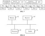
- FIG. 7 is a diagram illustrating the structure of a data processing network for data modulation in a data transmission method according to an embodiment of the present application.
- the data sequence [ b ( m )] composed of 0 and 1 experiences constellation modulation to form the data sequence [ d ( i )], where the constellation modulation is ⁇ /2-BPSK.
- Each of the N pieces of data is the sum of the two adjacent pieces of data multiplied by 2 2 .
- the time-domain data sequence [ x ( j )] is formed.
- j 1, 2, ..., J.
- the data sequence [ d ( i )] is the time-domain data sequence [ x ( j )]
- the constellation modulation of the data sequence [ d ( i )] is ⁇ /2-BPSK
- the constellation modulation of the time-domain data sequence [ x ( j )] is also ⁇ /2-BPSK.
- the time-domain data sequence [ x ( j )] experiences a Fourier transform to form the frequency-domain data sequence [ X ( j )].
- the frequency-domain data sequence [ X ( j )] experiences frequency-domain shaping or filtering by a root-raised cosine function, that is, pointwise multiplication is performed between the frequency-domain data sequence [ X ( j )] and the predefined frequency-domain data sequence [ Z ( j )], to form the frequency-domain data sequence [ S ( j )].
- the data sequence [ S ( j )] is expressed as follows:
- [ S ( j )] [ x (1) ⁇ z (1), x (2) ⁇ z (2), ⁇ , x ( J ) ⁇ z ( J )] .
- ⁇ denotes multiplication.
- the frequency-domain data sequence [ Z ( j )] is generated using the root-raised cosine function.
- the root-raised cosine function is discretely sampled to obtain the frequency-domain data sequence [ Z ( j )].
- the sampling interval of the discrete sampling is the same as the frequency-domain interval between adjacent pieces of data in the frequency-domain data sequence [ X ( j )]. That is, the discrete sampling interval is the same as the subcarrier spacing.
- the data sequence [ S ( k )] experiences an inverse Fourier transform to form the data sequence [ s ( k )].
- the data sequence [ s ( k )] is transmitted on a physical time-frequency resource.
- An embodiment of the present application provides a data transmission device.
- the device includes a memory configured to store a program; and a processor configured to execute the program to perform a pointwise multiplication between a first data sequence and a second data sequence to obtain a third data sequence, where the first data sequence and the second data sequence are each a frequency-domain data sequence; perform an inverse Fourier transform on the third data sequence to obtain a fourth data sequence; and transmit the fourth data sequence on a physical time-frequency resource.
- FIG. 8 is a diagram illustrating the structure of a data transmission device according to an embodiment of the present application.
- the data transmission device includes a processor 81, a memory 82, a receiver 83, and a sender 84.
- processors 81 may be configured in the data transmission device.
- FIG. 8 uses one processor by way of example.
- the processor 81, the memory 82, the receiver 83, and the sender 84 in the data transmission device may be connected by a bus or in other manners.
- FIG. 8 uses connection by a bus by way of example.
- the memory 82 is configured to store software programs, computer-executable programs, and modules, for example, program instructions/modules corresponding to the data transmission method of the embodiment shown in FIG. 1 of the present application.
- the processor 81 is configured to execute the software programs, instructions, and modules stored in the memory 82 to perform various functions and data processing of the data transmission device, that is, to implement the data transmission method.
- the memory 82 may mainly include a program storage region and a data storage region.
- the program storage region may store an operating system and an application program required by at least one function.
- the data storage region may store data created according to the use of the data transmission device.
- the memory 82 may include a high-speed random-access memory and may also include a nonvolatile memory such as at least one disk memory, a flash memory, or another nonvolatile solid-state memory.
- the receiver 83 is a combination of one or more devices or modules having a wireless signal receiving capability.
- the sender 84 is a combination of one or more devices or modules having a wireless signal sending capability.
- An embodiment of the present application provides a storage medium storing computer-executable instructions which, when executed by a computer processor, cause the computer processor to perform a data transmission method.
- the method includes performing a pointwise multiplication between a first data sequence and a second data sequence to obtain a third data sequence, where the first data sequence and the second data sequence are each a frequency-domain data sequence; performing an inverse Fourier transform on the third data sequence to obtain a fourth data sequence; and transmitting the fourth data sequence on a physical time-frequency resource.
Landscapes
- Engineering & Computer Science (AREA)
- Signal Processing (AREA)
- Computer Networks & Wireless Communication (AREA)
- Physics & Mathematics (AREA)
- Discrete Mathematics (AREA)
- General Physics & Mathematics (AREA)
- Mathematical Physics (AREA)
- Digital Transmission Methods That Use Modulated Carrier Waves (AREA)
- Compression, Expansion, Code Conversion, And Decoders (AREA)
Abstract
Provided are a data transmission method and device and a storage medium. The data transmission method includes performing (S110) pointwise multiplication between a first data sequence and a second data sequence to obtain a third data sequence, where the first data sequence and the second data sequence are each a frequency-domain data sequence; performing (S120) an inverse Fourier transform on the third data sequence to obtain a fourth data sequence; and transmitting (S130) the fourth data sequence on a physical time-frequency resource.
Description
- The present application relates to the field of wireless communications, for example, a data transmission method and device and a storage medium.
- In the fifth-generation (5G) mobile communication technology, frequency bands can be divided into high-frequency bands and low-frequency bands. High-frequency bands are millimeter-wave bands while low-frequency bands overlap the frequency bands used in the fourth-generation (4G) mobile communication technology. Low-frequency bands are primarily used for Massive Machine-Type Communications (mMTC) services while high-frequency bands are primarily used for enhanced Mobile BroadBand (eMBB) services and Ultra-Reliable Low-Latency Communications (URLLC) services.
- High-frequency bands experience significant path loss and shadow fading, resulting in very low signal-to-noise ratios (SNR) in certain areas at the cell edge. Additionally, in high-frequency scenarios, the efficiency of a power amplifier (PA) is relatively low. To improve the signal-to-interference-plus-noise ratio (SINR) while conserving battery power for a user equipment (UE), it is necessary for the peak-to-average power ratio (PAPR) of the signals transmitted by the UE to be kept low.
- In mMTC scenarios, some UEs aim to significantly reduce power consumption, with a desired battery life of over ten years. To improve the efficiency of the PA of a UE, it is also necessary to maintain a low PAPR for the signals transmitted by the UE. Especially when a large number of users are accessing the network non-orthogonally, the SINR may be very low. Consequently, there is a demand for a low-order modulation and coding scheme (MCS) with a low PAPR for signal modulation.
- In the 5G New Radio (NR) standard, signals modulated using discrete Fourier transform-spread-orthogonal frequency-division multiplexing (DFT-s-OFDM) have a relatively low PAPR, still not satisfying the application scenarios that demand an even lower PAPR in the Beyond 5G (B5G) or sixth-generation (6G) mobile communication technology.
- Embodiments of the present application provide a data transmission method and device and a storage medium.
- In a first aspect, an embodiment of the present application provides a data transmission method. The method includes performing a pointwise multiplication between a first data sequence and a second data sequence to obtain a third data sequence, where the first data sequence and the second data sequence are each a frequency-domain data sequence; performing an inverse Fourier transform on the third data sequence to obtain a fourth data sequence; and transmitting the fourth data sequence on a physical time-frequency resource.
- In a second aspect, an embodiment of the present application provides a data transmission device. The device includes a memory configured to store a program; and a processor configured to execute the program to perform a pointwise multiplication between a first data sequence and a second data sequence to obtain a third data sequence, where the first data sequence and the second data sequence are each a frequency-domain data sequence; perform an inverse Fourier transform on the third data sequence to obtain a fourth data sequence; and transmit the fourth data sequence on a physical time-frequency resource.
- In a third aspect, an embodiment of the present application provides a storage medium. The storage medium stores a program. When the program is executed, the data transmission method of any embodiment of the present application is performed.
- The data transmission method and device and the storage medium according to embodiments of the present application involve performing an inverse Fourier transform on a data sequence generated by pointwise multiplication between two frequency-domain data sequences; and then transmitting the data sequence after the inverse Fourier transform on a physical time-frequency resource, thereby effectively reducing the PAPR of the transmitted data sequence.
-
-
FIG. 1 is a flowchart of a data transmission method according to an embodiment of the present application. -
FIG. 2 is a diagram illustrating the insertion of one piece of data between two adjacent pieces of data. -
FIG. 3 is a diagram illustrating the insertion of two pieces of data between two adjacent pieces of data. -
FIG. 4 is a waveform diagram of a root-raised cosine function according to an embodiment of the present application. -
FIG. 5 is a diagram of a data sequence according to an embodiment of the present application. -
FIG. 6 is a diagram of a data sequence according to an embodiment of the present application. -
FIG. 7 is a diagram illustrating the structure of a data processing network for data modulation in a data transmission method according to an embodiment of the present application. -
FIG. 8 is a diagram illustrating the structure of a data transmission device according to an embodiment of the present application. - Embodiments of the present application are described hereinafter in conjunction with drawings.
-
FIG. 1 is a flowchart of a data transmission method according to an embodiment of the present application. As shown inFIG. 1 , the data transmission method of this embodiment includes S110 to S130. - In S110, pointwise multiplication is performed between a first data sequence and a second data sequence to obtain a third data sequence, where the first data sequence and the second data sequence are each a frequency-domain data sequence.
- The data transmission method of this embodiment can be applied to any node in a wireless communication system, particularly a user equipment (UE) in this system. To address the problem of high PAPR in signal transmission from nodes in wireless communications, this embodiment of the present application provides a signal modulation scheme. Modulation using this signal modulation scheme before transmission enables a lower PAPR.
- In this embodiment, pointwise multiplication is performed between a first data sequence and a second data sequence to obtain a third data sequence. The first data sequence is a to-be-transmitted data sequence while the second data sequence is a preset data sequence. The first data sequence and the second data sequence are each a frequency-domain data sequence. Pointwise multiplication between the first data sequence and the second data sequence can also be referred to as frequency-domain shaping of the first data sequence, with the second data sequence as the frequency-domain shaping function. The pointwise multiplication can also be referred to as a filtering operation, with the second data sequence as the filtering function.
- In this embodiment of the present application, the first data sequence is denoted as [X (j )], the second data sequence is denoted as [Z (j )], and the third data sequence is denoted as [S (j )].
- For example, the first data sequence is [X (j )] = [x (1), x (2), ..., x (J)], the second data sequence is [Z (j )] = [z (1), z (2), ..., z (J)] and the third data sequence is [S(j)] = [x(1) · z(1), x(2) · z(2), ···,x(J) · z(J)]. Here · denotes multiplication. The length of the first data sequence and the length of the second data sequence may be the same or different. That is, the length J of the first data sequence [X (j )] and the length J of the second data sequence [Z (j )] may be the same or different.
- In an embodiment, the second data sequence may be generated using a root-raised cosine function. The root-raised cosine function is a frequency-domain compressed root-raised cosine function. The value range of the roll-off factor of the root-raised cosine function is [0.7, 1]. The ratio of the half-power bandwidth of the root-raised cosine function to the bandwidth occupied by the first data sequence is P/2. The value range of P is [0.9, 1.1]. In an embodiment, the half-power bandwidth of the root-raised cosine function is half of the bandwidth occupied by the first data sequence. That is, P = 1, indicating a compression rate of 50%. In an embodiment, the roll-off factor of the root-raised cosine function is 1.
- In an embodiment, the second data sequence is generated by discrete sampling on the root-raised cosine function.
- In an embodiment, the length of the independent variable corresponding to a non-zero function value of the root-raised cosine function is less than or equal to the bandwidth occupied by the first data sequence.
- In an embodiment, the root-raised cosine function

- y(f ) denotes a raised cosine function:

- Here A denotes a constant, α denotes the roll-off factor of the root-raised cosine function, 2f 0 denotes the half-power bandwidth of the root-raised cosine function, and 2f 0(1 + α) denotes the length of the independent variable corresponding to a non-zero function value of the root-raised cosine function.
- In an embodiment, the first data sequence is generated from a fifth data sequence by a Fourier transform. The fifth data sequence is a time-domain data sequence. The fifth data sequence is generated from a sixth data sequence. The sixth data sequence is formed by constellation modulation of a seventh data sequence composed of 0 and 1. Constellation modulation of the sixth data sequence is π/2-binary phase-shift keying (π/2-BPSK). In an embodiment, the sixth data sequence is a reference sequence. The constellation modulation of the reference sequence is π/2-BPSK. The sixth data sequence contains L pieces of reference sequence data as well as constellation-modulated data. L ≥ 0. In this embodiment of the present application, the fifth data sequence is denoted as [x (j )], the sixth data sequence is denoted as [d (i )], and the seventh data sequence is denoted as [b (m)].
- The fifth data sequence is generated from the sixth data sequence in the following manner: N pieces of new data are inserted between each two adjacent pieces of data in the sixth data sequence. Here each of the N pieces of new data is the sum of the two adjacent pieces of data multiplied by


- In S120, an inverse Fourier transform is performed on the third data sequence to obtain a fourth data sequence.
- After the third data sequence is obtained, an inverse Fourier transform is performed on the third data sequence to generate a fourth data sequence. When generating the fourth data sequence, it is feasible to perform the inverse Fourier transform on the third data sequence, meaning that oversampling is not required. Additionally, when oversampling is required, it is feasible to perform a zero-padding operation on the third data sequence to form a new data sequence and then perform the inverse Fourier transform on the new data sequence to generate the fourth data sequence. In this embodiment of the present application, the fourth data sequence is denoted as [s (k)].
- When oversampling is not required, the fourth data sequence is, for example, [s (k)], and J = K. Here k = 1,2,..., K. When oversampling is required, the fourth data sequence is, for example, [s (k)], and J < K. Here k = 1,2,..., K.
- In S130, the fourth data sequence is transmitted on a physical time-frequency resource.
- After being generated, the fourth data sequence can be transmitted on a physical time-frequency resource. This effectively reduces the PAPR of the transmitted fourth data sequence. The reason for this is that frequency-domain pointwise multiplication is equivalent to time-domain data convolution. A predesigned weight coefficient sequence forms the time-domain discrete data of a well-designed frequency-domain data sequence. When a set of discrete time-domain data is convolved with this designed set of discrete data, the correlation between adjacent data improves, thereby effectively reducing the PAPR of the transmitted data sequence. When the frequency-domain data sequence corresponding to this set of discrete time-domain data is generated using a root-raised cosine function, the data correlation is better optimized.
- Before transmitting the fourth data sequence on the physical time-frequency resource, it is also feasible to filter the fourth data sequence.
- The data transmission method of this embodiment of the present application involves performing an inverse Fourier transform on a data sequence generated by pointwise multiplication between two frequency-domain data sequences; and then transmitting the data sequence after the inverse Fourier transform on a physical time-frequency resource, thereby effectively reducing the PAPR of the transmitted data sequence.
- In this embodiment, when no data is inserted into the sixth data sequence, that is, N is equal to 0, that is, the sixth data sequence is used as the fifth data sequence, then the fifth data sequence is π/2-BPSK modulated data that has a relatively low PAPR. When the value of N is 1, that is, one piece of data is inserted between each two adjacent pieces of data in the sixth data sequence. The phase difference between the two adjacent pieces of data becomes π/4 from π/2 after the data insertion. This reduces the PAPR of the transmitted data sequence, resulting in a lower PAPR than that in π/2-BPSK constellation modulation.
- The half-power bandwidth of the root-raised cosine function is half of the bandwidth occupied by the first data sequence. The roll-off factor of the root-raised cosine function is 1. The advantage is that no additional frequency-domain bandwidth is occupied, the transmitted data sequence has a low PAPR, and demodulation at the receiving end is not affected. This is because when the roll-off factor of the root-raised cosine function is 1, the bandwidth of the root-raised cosine function is the same as the bandwidth occupied by the first data sequence, indicating a compression rate of 50% in the frequency domain. This manifests as the position of the zero point of the side lobes of the time-domain waveform of the frequency-domain-compressed root-raised cosine function being different from the position of the zero point of the side lobes of the waveform of the sinc function. However, the time-domain data are either π/2-BPSK constellation-modulated data or interpolated from such data. As a result, the adjacent data are located on different directional axes, ensuring that the demodulation at the receiving end remains unaffected. Through this well-designed frequency-domain root-raised cosine function, the PAPR of the time-domain signal can be significantly reduced, demodulation of the time-domain data remains unaffected, and no additional frequency domain bandwidth is occupied.
- In an embodiment, the sixth data sequence is a reference sequence. The constellation modulation of the reference sequence is π/2-BPSK. Thus, the reference sequence also has a low PAPR, and when the value of N is 1, this reference sequence is used for channel estimation, resulting in a better performance at the receiving end.
- In an embodiment of
FIG. 1 , the second data sequence may be generated using a raised cosine function. The raised cosine function is a frequency-domain compressed raised cosine function. The value range of the roll-off factor of the raised cosine function is [0.7, 1]. The ratio of the half-power bandwidth of the raised cosine function to the bandwidth occupied by the first data sequence is P/2. The value range of P is [0.9, 1.1]. In an embodiment, the half-power bandwidth of the raised cosine function is half of the bandwidth occupied by the first data sequence. That is, P = 1, indicating a compression rate of 50%. In an embodiment, the roll-off factor of the raised cosine function is 1. In an embodiment, the second data sequence is generated by discrete sampling on the raised cosine function. In an embodiment, the length of the independent variable corresponding to a non-zero function value of the raised cosine function is less than or equal to the bandwidth occupied by the first data sequence. - The raised cosine function y(f ) satisfies the following formula:

- Here A denotes a constant, α denotes the roll-off factor of the raised cosine function, 2f 0 denotes the half-power bandwidth of the raised cosine function, and 2f 0(1 + α) denotes the length of the independent variable corresponding to a non-zero function value of the raised cosine function.
- The following describes the data transmission method of the present application in conjunction with embodiments:
- The frequency-domain data sequence [X (j )] = [x (1), x (2), ..., x (J )]. The predefined frequency-domain data sequence[Z (j )] = [z (1), z (2), ..., z (J)]. The frequency-domain data sequence [X (j )] is pointwise-multiplied by the predefined frequency-domain data sequence [Z (j )] to form the data sequence [S (j )]. The data sequence[S(j)] is expressed as follows:
- [S(j)] = [x(1) · z(1), x(2) · z(2), ··· , x(J) · z(J)]. Here · denotes multiplication.
- If oversampling is not required, the data sequence [S (j )] experiences an inverse Fourier transform to form the data sequence [s (k)]. Here k = 1,2,..., K, and J = K.
- If oversampling is required, a zero-padding operation is performed on the data sequence [S(j)] to form the data sequence [S(k)], and the data sequence [S(k)] experiences an inverse Fourier transform to form the data sequence [s (k)]. Here k = 1,2,..., K, and J < K
- The data sequence [s(k)] is transmitted on a physical time-frequency resource.
- The frequency-domain data sequence [X(j)] is pointwise-multiplied by the predefined frequency-domain data sequence [Z(j)] to form the data sequence [S(j)].
- The frequency-domain data sequence [X(j)] is formed from the time-domain data sequence [x (j)] by a Fourier transform. The time-domain data sequence [x (j)] is generated from the data sequence [d(i)]. The constellation modulation of the data sequence [d (i )] is π/2-BPSK. The data sequence [d (i)] is the data sequence [X (j )].
- In this embodiment, the data sequence [d (i ) = [d(0) , d(1) , d(2), d(3) , d(4) = [1, 1j , -1, -j, 1] , i = 0, 1, 2, 3, 4], the data sequence [d(i )] is the data sequence [x(j )], and the sequence [x(j) = [x(0) , x(1) , x(2) , x(3) , x(4)] = [d(0) , d(1) , d(2) , d(3) , d(4)] = [1, 1j, -1, -j, 1], j = 0, 1, 2, 3, 4]
- The frequency-domain data sequence [X(j)] is pointwise-multiplied by the predefined frequency-domain data sequence [Z(j)] to form the data sequence [S (j )].
- The frequency-domain data sequence [X(j)] is formed from the time-domain data sequence [x(j)] by a Fourier transform. The time-domain data sequence [x(j)] is generated from the data sequence [d(i)]. The constellation modulation of the data sequence [d(i )] is π/2-BPSK. One piece of data is inserted between each two adjacent pieces of data in the data sequence [d (i )], and the inserted piece of data is the sum of the two adjacent pieces of data multiplied by

- In this embodiment, the data sequence [d(i ) = [d(0) , d(1) , d(2) , d(3) , d(4) = [1, 1j , - 1, - j , 1] , i = 0, [1, 2, 3, 4], and the time-domain data sequence

- The frequency-domain data sequence [X (j )] is pointwise-multiplied by the predefined frequency-domain data sequence [Z(j)] to form the data sequence [S (j )].
- The frequency-domain data sequence [X(j)] is formed from the time-domain data sequence [x(j)] by a Fourier transform. The time-domain data sequence [x(j)] is generated from the data sequence [d(j)] . N pieces of data are inserted between each two adjacent pieces of data in the data sequence [d (i )] . Each of the N pieces of data is the sum of the two adjacent pieces of data multiplied by

- In this embodiment, the data sequence [d(i ) = [d(0) , d(1) , d(2) , d(3) , d(4) = [1, 1j , - 1, - j, 1], i = 0, 1, 2, 3, 4]. N pieces of data are inserted between each two adjacent pieces of data in the data sequence [d (i )]. The value of N is 0. That is, no data is inserted between each two adjacent pieces of data in the data sequence [d (i )]. The data sequence [d (i)] is the data sequence [x (j )]. The sequence

- The frequency-domain data sequence [X (j )] is pointwise-multiplied by the predefined frequency-domain data sequence [Z (j )] to form the data sequence [S (j)].
- The frequency-domain data sequence [X (j)] is formed from the time-domain data sequence [X(j)] by a Fourier transform. The time-domain data sequence [x(j )] is generated from the data sequence [d (i )]. N pieces of data are inserted between each two adjacent pieces of data in the data sequence [d (i )]. Each of the N pieces of data is the sum of the two adj acent pieces of data multiplied by

- In this embodiment, the data sequence [d(i ) = [d( 0) , d( 1) , d( 2) , d(3) , d(4) = [ 1, 1j , - 1, -j , 1] , i = 0, [1, 2, 3, 4] . N pieces of data are inserted between each two adjacent pieces of data in the data sequence [d(i)]. The value of N is 1. That is, one piece of data is inserted between each two adjacent pieces of data in the data sequence [d(i )], and the inserted piece of data is the sum of the two adjacent pieces of data multiplied by


- The data sequence d( 0) is the time-domain data sequence x(0) . That is, x( 0) = d( 0) = 1. One piece of data is inserted between the data sequence d( 0) and the data sequence d(1) to form the time-domain data sequence x( 1). The time-domain data sequence x( 1) is the sum of the data sequence d( 0) and the data sequence d(1) multiplied by


- The frequency-domain data sequence [X (j )] is pointwise-multiplied by the predefined frequency-domain data sequence [Z (j )] to form the data sequence [S (j )].
- The frequency-domain data sequence [X (j )] is formed from the time-domain data sequence [x (j )] by a Fourier transform. The time-domain data sequence [x (j )] is generated from the data sequence [d (i )]. N pieces of data are inserted between each two adjacent pieces of data in the data sequence [d (i )]. The magnitude of each of the inserted N pieces of data is the same as the magnitude of each of the two adjacent pieces of data. The phase difference between adjacent pieces of data obtained after the N pieces of data are inserted is

- In this embodiment, the data sequence [d(i ) = [d( 0) , d( 1) , d( 2) , d(3), d( 4) = [1, 1j , - 1, -j , 1] , i = 0, 1, 2, 3, 4]. N pieces of data are inserted between each two adjacent pieces of data in the data sequence [d (i )]. The magnitude of each of the inserted N pieces of data is the same as the magnitude of each of the two adjacent pieces of data. The phase difference between adjacent pieces of data obtained after the N pieces of data are inserted is

- When the value of N is 0, no data is inserted between each two adjacent pieces of data in the data sequence [d (i )], the data sequence [d (i )] is the data sequence [x (j )], the constellation modulation of the data sequence [d (i )] is π/2-BPSK, and the constellation modulation of the data sequence [x (j )] is also π/2-BPSK. The data sequence [x (j )] has the same magnitude. The phase difference between adjacent pieces of data

FIG. 2 is a diagram illustrating the insertion of one piece of data between two adjacent pieces of data. InFIG. 2 , the horizontal axis represents the real part of the data, and the vertical axis represents the imaginary part of the data. The data sequence d( 0) is the time-domain data sequence x( 0). One piece of data is inserted between the data sequence d( 0) and the data sequence d( 1) to form the time-domain data sequence x( 1). The data sequence d( 1) is the time-domain data sequence x( 2). One piece of data is inserted between the data sequence d( 1) and the data sequence d( 2) to form the time-domain data sequence x( 3). The data sequence d( 2) is the time-domain data sequence x( 4). One piece of data is inserted between the data sequence d( 2) and the data sequence d( 3) to form the time-domain data sequence x( 5). The data sequence d( 3) is the time-domain data sequence x( 6). One piece of data is inserted between the data sequence d( 3) and the data sequence d( 4) to form the time-domain data sequence x( 7). The data sequence d( 4) is the time-domain data sequence x( 8). The data sequence [x (j )] has magnitudes [1, 1, 1, 1, 1, 1, 1, 1, 1]. The magnitude of each of the inserted pieces of data [x( 1) , x( 3) , x( 5) , x( 7)] is the same as the magnitude of each of the two adjacent pieces of data [x( 0)x( 2) , x( 2)x( 4) , x( 4)x( 6), x( 6)x( 8)] x( 0) , x(1) , x(2) , x( 3) , x(4) , x( 5) , x( 6) , x( 7) , x( 8) hasphases 


- When the value of N is 2, that is, two pieces of data are inserted between each two adjacent pieces of data in the data sequence [d (i )] to form the time-domain data sequence [x (j )]. The time-domain data sequence [x(j ) = [x( 0) , x( 1) , x( 2) , x( 3) , x( 4) , x( 5) , x( 6) , x( 7) , x( 8) , x( 9) , x( 10) , x( 11) , x( 12)].
FIG. 3 is a diagram illustrating the insertion of two pieces of data between two adjacent pieces of data. InFIG. 3 , the horizontal axis represents the real part of the data, and the vertical axis represents the imaginary part of the data. The data sequence d( 0) is the time-domain data sequence x( 0). Two pieces of data which are inserted between the data sequence d( 0) and the data sequence d(1) are two time-domain data sequences x( 1) and x( 2). The data sequence d( 1) is the time-domain data sequence x(3). Two pieces of data which are inserted between the data sequence d( 1) and the data sequence d( 2) are two time-domain data sequences x(4) and x( 5). The data sequence d( 2) is the time-domain data sequence x( 6). Two pieces of data which are inserted between the data sequence d( 2) and the data sequence d( 3) are two time-domain data sequences x( 7) and x( 8). The data sequence d( 3) is the time-domain data sequence x( 9). Two pieces of data which are inserted between the data sequence d( 3) and the data sequence d( 4) are two time-domain data sequences x( 10) and x( 11). The data sequence d( 4) is the time-domain data sequence x( 12). The data sequence [x (j )] has magnitudes [1, 1, 1, 1, 1, 1, 1, 1, 1, 1, 1, 1 ,1]. The magnitude of each of the inserted pieces of data [x( 1) , x( 2) , x( 4) , x( 5) , x( 7), x( 8), x( 10) , x( 11)] is the same as the magnitude of each of the two adjacent pieces of data [x( 0)x( 2) , x( 1)x( 3) , x( 3)x( 5) , x( 4)x( 6) , x( 6)x( 8) , x( 7)x( 9) , x( 9)x( 11) , x( 10)x( 12)] [x( 0) , x( 1) , x( 2) , x( 3) , x( 4) , x( 5) , x( 6) , x( 7) , x( 8) , x( 9) , x( 10) , x( 11) , x( 12)] has phases


- The advantage of this embodiment is that each piece of data in a data sequence has the same magnitude. The phase difference between adjacent pieces of data after the insertion is

- The frequency-domain data sequence [X (j )] is pointwise-multiplied by the predefined frequency-domain data sequence [Z (j )] to form the data sequence [S (j )].
- The predefined frequency-domain data sequence [Z (j )] is generated using a root-raised cosine function. For example, the root-raised cosine function is discretely sampled to obtain the frequency-domain data sequence [Z (j )]. The sampling interval of the discrete sampling is the same as the frequency-domain interval between adjacent pieces of data in the frequency-domain data sequence [X (j )]. That is, the discrete sampling interval is the same as the subcarrier spacing.
- Assuming that the frequency-domain raised cosine function y(f ) is expressed as follows:

- then the frequency-domain root-raised cosine function (that is, the square root of the raised cosine function) sry(f ) satisfies

- Here A denotes a constant, α denotes the roll-off factor, 2f 0 denotes the half-power bandwidth of the frequency-domain raised cosine function. In this embodiment, 2f 0 denotes the half-power bandwidth of the root-raised cosine function, and 2f 0(1 + α) denotes the length of the root-raised cosine function (that is, the length of the independent variable corresponding to a non-zero function value of the root-raised cosine function).
- In this embodiment, the values of the roll-off factor α of the root-raised cosine function are [0.7, 0.8, 0.9, 1].
FIG. 4 is a waveform diagram of a root-raised cosine function according to an embodiment of the present application. As shown inFIG. 4 , when the value of α is 0.7, the length of the root-raised cosine function is 3. 4f 0; when the value of α is 0.8, the length of the root-raised cosine function is 3. 6f 0; when the value of α is 0.9, the length of the root-raised cosine function is 3. 8f 0; when the value of α is 1, the length of the root-raised cosine function is 4f 0. The length of the root-raised cosine function is the length of the independent variable corresponding to a non-zero function value of the root-raised cosine function. - The frequency-domain data sequence [X (j )] is pointwise-multiplied by the predefined frequency-domain data sequence [Z(j )] to form the data sequence [S (j )].
- The predefined frequency-domain data sequence [Z (j )] is generated using a root-raised cosine function. The value range of the roll-off factor α of the root-raised cosine function is [0.7, 1]. The ratio of the half-power bandwidth to the bandwidth occupied by the frequencydomain reference sequence [X (j )] is P/2. The value range of P is [0.9, 1.1].
- In the present application, 2f 0 denotes the half-power bandwidth of the frequency-domain root-raised cosine function, and 2f 0(1 + α) denotes the length of the frequency-domain root-raised cosine function. In this embodiment, the value of the roll-off factor α of the root-raised cosine function is 1, that is, the length of the frequency-domain root-raised cosine function is 2f 0( 1 + α) = 4f 0. In this embodiment, the bandwidth occupied by the frequency-domain data sequence [X (j )] is 4f 0, that is, the half-power bandwidth 2f 0 of the root-raised cosine function is half of the bandwidth 4f 0 occupied by the frequency-domain data sequence [X(j)]. Here

- The frequency-domain data sequence [X(j)] is pointwise-multiplied by the predefined frequency-domain data sequence [Z(j)] to form the data sequence [S(j)].
- The predefined frequency-domain data sequence [Z(j)] is generated using a root-raised cosine function. The value range of the roll-off factor α of the root-raised cosine function is [0.7, 1]. The ratio of the half-power bandwidth to the bandwidth occupied by the frequency-domain reference sequence [X(j)] is P/2. The value range of P is [0.9, 1.1].
- In the present application, 2f 0 denotes the half-power bandwidth of the frequency-domain root-raised cosine function, and 2f 0(1 + α) denotes the length of the frequency-domain root-raised cosine function. In this embodiment, the value of the roll-off factor α of the root-raised cosine function is 0.7, that is, the length of the frequency-domain root-raised cosine function is 2f 0(1 + α) = 3. 4f 0. In this embodiment, the bandwidth occupied by the frequency-domain data sequence [X(j)] is 4f 0, that is, the half-power bandwidth 2f 0 of the root-raised cosine function is half of the bandwidth 4f 0 occupied by the frequency-domain data sequence [X(j)]. Here

- The frequency-domain data sequence [X(j)] is pointwise-multiplied by the predefined frequency-domain data sequence [Z(j)] to form the data sequence [S(j)].
- The predefined frequency-domain data sequence [Z(j)] is generated using a root-raised cosine function. The value range of the roll-off factor α of the root-raised cosine function is [0.7, 1]. The ratio of the half-power bandwidth to the bandwidth occupied by the frequency-domain reference sequence [X(j)] is P/2. The value range of P is [0.9, 1.1].
- In the present application, 2f 0 is defined as the half-power bandwidth of the frequency-domain root-raised cosine function. In this embodiment, the bandwidth occupied by the frequency-domain data sequence [X(j)] is


- The frequency-domain data sequence [X(j)] is pointwise-multiplied by the predefined frequency-domain data sequence [Z(j)] to form the data sequence [S(j)].
- The predefined frequency-domain data sequence [Z(j)] is generated using a root-raised cosine function. The value range of the roll-off factor α of the root-raised cosine function is [0.7, 1]. The ratio of the half-power bandwidth to the bandwidth occupied by the frequency-domain reference sequence [X(j)] is P/2. The value range of P is [0.9, 1.1].
- In the present application, 2f 0 is defined as the half-power bandwidth of the frequency-domain root-raised cosine function. In this embodiment, the bandwidth occupied by the frequency-domain data sequence [X(j)] is


-
FIG. 5 is a diagram of a data sequence according to an embodiment of the present application.FIG. 5 illustrates an example in which the data sequence [d(i)] contains L pieces of reference sequence data as well as constellation-modulated data. Here L ≥ 0. - In
FIG. 5 , the data sequence [b(m)] composed of 0 and 1 experiences constellation modulation to form the data sequence [d(i)]. The constellation modulation of the data sequence [b(m)] is π/2-BPSK. The data sequence [d(i)] contains L pieces of reference sequence data as well as constellation-modulated data. In this embodiment, L = 2. There is one piece of reference sequence data L 1 before the constellation-modulated data sequence [d(i)] and one piece of reference sequence data L 2 after the constellation-modulated data sequence [d(i)]. The data sequence [d(i)] contains constellation-modulated data and L pieces of reference sequence data to form one data block. The length of this data block is equal to the length of one OFDM symbol. The length of this data block is also equal to the length of one FFT window. - In this embodiment, the data sequence [d(i)] is a reference sequence. N pieces of data are inserted between each two adjacent pieces of data in the reference sequence The data is the sum of the two adjacent pieces of data multiplied by

- When the value of N is 0, no data is inserted between each two adjacent pieces of data in the reference sequence [d(i)], and the reference sequence [d(i)] is used as the time-domain reference sequence [x(j)].
- When the value of N is 1, one piece of data is inserted between each two adjacent pieces of data in the reference sequence [d(i)], and the inserted piece of data is the sum of the two adjacent pieces of data multiplied by

- Then the time-domain reference sequence [x(j)] experiences a Fourier transform to form the frequency-domain reference sequence [X(j)]. The frequency-domain reference sequence [X(j)] is pointwise-multiplied by the predefined frequency-domain data sequence [Z(j)] to form the reference sequence [S(j)]. Here j = 1, 2, ... , J, k = 1, 2, ... , K, J and K are each a positive integer, and J ≤ K.
- The predefined frequency-domain data sequence [Z(j)] is generated using a root-raised cosine function. The value range of the roll-off factor α of the root-raised cosine function is [0.7, 1]. The ratio of the half-power bandwidth to the bandwidth occupied by the frequency-domain reference sequence [X(j)] is P/2. The value range of P is [0.9, 1.1].
- When J = K, it is feasible to perform an inverse Fourier transform on the reference sequence [S(j)] to form the reference sequence [s(k)].
- When J < K, it is feasible to perform a zero-padding operation on the reference sequence [S(j)] to form the data sequence [S(k)] and then perform an inverse Fourier transform on the data sequence [S(k)] to form the data sequence [s(k)] .
- Then the data sequence [s(k)] is transmitted on a physical time-frequency resource.
-
FIG. 6 is a diagram of a data sequence according to an embodiment of the present application.FIG. 6 shows one reference sequence [d 0(i)] and two data sequences[d 1(i)] and [d 2(i)]. - The data sequences [d 1(i)] and [d 2(i)] contain L pieces of reference sequence data as well as constellation-modulated data. In this embodiment, L = 2. The first data sequence [d 1(i)] contains two pieces of reference sequence data L 1,1 and L 1,2 as well as constellation-modulated data. The second data sequence [d 2(i)] contains two pieces of reference sequence data L 2,1 and L 2,2 as well as constellation-modulated data.
- The first piece of reference sequence data L 1,1 in the first data sequence [d 1(i)] is the same as the reference sequence data corresponding to the position L 0,1 of the reference sequence [d 0(i)]. The first piece of reference sequence data L 2,1 in the second data sequence [d 2(i)] is the same as the reference sequence data corresponding to the position L 0,1 of the reference sequence [d 0(i)]. The second piece of reference sequence data L 1,2 in the first data sequence [d 1(i)] is the same as the reference sequence data corresponding to the position L 0,2 of the reference sequence [d 0(i)]. The second piece of reference sequence data L 2,2 in the second data sequence [d 2(i)] is the same as the reference sequence data corresponding to the position L 0,2 of the reference sequence [d 0(i)].
- The frequency-domain data sequence [X(j)] is pointwise-multiplied by the predefined time-domain data sequence [Z(j)] to form the data sequence [S(j)]. Here [X(j)] = [x(1), x(2), ..., x(J)], and [Z(j)] = [z(1), z(2), ..., z(J)]. The data sequence [S(j)] is expressed as follows:

- If oversampling is not required, the data sequence [S(k)] experiences an inverse Fourier transform to form the data sequence [s(k)] . Here k = 1, 2, ... , K, and J = K.
- If oversampling is required, a zero-padding operation is performed on the data sequence [S(j)] to form the data sequence [S(k)], and the data sequence [S(k)] experiences an inverse Fourier transform to form the data sequence [s(k)]. Here k = 1, 2, ... , K , and J < K
- Then the data sequence [s(k)] is transmitted on a physical time-frequency resource after being filtered.
-
FIG. 7 is a diagram illustrating the structure of a data processing network for data modulation in a data transmission method according to an embodiment of the present application. As shown inFIG. 7 , the data sequence [b(m)] composed of 0 and 1 experiences constellation modulation to form the data sequence [d(i)], where the constellation modulation is π/2-BPSK. Then N pieces of data (where N = 0 or 1) are inserted between each two adjacent pieces of data in the data sequence [d(i)]. Each of the N pieces of data is the sum of the two adjacent pieces of data multiplied by
- When the value of N is 0, no data is inserted between each two adjacent pieces of data in the data sequence [d(i)], the data sequence [d(i)] is the time-domain data sequence [x(j)], the constellation modulation of the data sequence [d(i)] is π/2-BPSK, and the constellation modulation of the time-domain data sequence [x(j)] is also π/2-BPSK. When the value of N is 1, one piece of data is inserted between each two adjacent pieces of data in the data sequence [d(i)], and the data is the sum of the two adjacent pieces of data multiplied by

- [S(j)] = [x(1) · z(1), x(2) · z(2), ···, x(J) · z(J)]. Here · denotes multiplication.
- The frequency-domain data sequence [Z(j)] is generated using the root-raised cosine function. For example, the root-raised cosine function is discretely sampled to obtain the frequency-domain data sequence [Z(j)]. The sampling interval of the discrete sampling is the same as the frequency-domain interval between adjacent pieces of data in the frequency-domain data sequence [X(j)]. That is, the discrete sampling interval is the same as the subcarrier spacing.
- If oversampling is not required, the data sequence [S(k)] experiences an inverse Fourier transform to form the data sequence [s(k)]. Here k = 1, 2, ... , K, and J = K.
- If oversampling is required, a zero-padding operation is performed on the data sequence [S(j)] to form the data sequence [S(k)], and the data sequence [S(k)] experiences an inverse Fourier transform to form the data sequence [s(k)]. Here k = 1, 2, ... , K, and J < K
- Then the data sequence [s(k)] is transmitted on a physical time-frequency resource.
- An embodiment of the present application provides a data transmission device. The device includes a memory configured to store a program; and a processor configured to execute the program to perform a pointwise multiplication between a first data sequence and a second data sequence to obtain a third data sequence, where the first data sequence and the second data sequence are each a frequency-domain data sequence; perform an inverse Fourier transform on the third data sequence to obtain a fourth data sequence; and transmit the fourth data sequence on a physical time-frequency resource.
-
FIG. 8 is a diagram illustrating the structure of a data transmission device according to an embodiment of the present application. As shown inFIG. 8 , the data transmission device includes aprocessor 81, amemory 82, areceiver 83, and asender 84. One ormore processors 81 may be configured in the data transmission device.FIG. 8 uses one processor by way of example. Theprocessor 81, thememory 82, thereceiver 83, and thesender 84 in the data transmission device may be connected by a bus or in other manners.FIG. 8 uses connection by a bus by way of example. - As a computer-readable storage medium, the
memory 82 is configured to store software programs, computer-executable programs, and modules, for example, program instructions/modules corresponding to the data transmission method of the embodiment shown inFIG. 1 of the present application. Theprocessor 81 is configured to execute the software programs, instructions, and modules stored in thememory 82 to perform various functions and data processing of the data transmission device, that is, to implement the data transmission method. - The
memory 82 may mainly include a program storage region and a data storage region. The program storage region may store an operating system and an application program required by at least one function. The data storage region may store data created according to the use of the data transmission device. Additionally, thememory 82 may include a high-speed random-access memory and may also include a nonvolatile memory such as at least one disk memory, a flash memory, or another nonvolatile solid-state memory. - The
receiver 83 is a combination of one or more devices or modules having a wireless signal receiving capability. Thesender 84 is a combination of one or more devices or modules having a wireless signal sending capability. - An embodiment of the present application provides a storage medium storing computer-executable instructions which, when executed by a computer processor, cause the computer processor to perform a data transmission method. The method includes performing a pointwise multiplication between a first data sequence and a second data sequence to obtain a third data sequence, where the first data sequence and the second data sequence are each a frequency-domain data sequence; performing an inverse Fourier transform on the third data sequence to obtain a fourth data sequence; and transmitting the fourth data sequence on a physical time-frequency resource.
Claims (28)
- A data transmission method, comprising:performing a pointwise multiplication between a first data sequence and a second data sequence to obtain a third data sequence, wherein the first data sequence and the second data sequence are each a frequency-domain data sequence;performing an inverse Fourier transform on the third data sequence to obtain a fourth data sequence; andtransmitting the fourth data sequence which is carried on a physical time-frequency resource.
- The method of claim 1, wherein the second data sequence is generated using a root-raised cosine function.
- The method of claim 2, wherein the root-raised cosine function is a frequency-domain compressed root-raised cosine function.
- The method of claim 2, wherein a value range of a roll-off factor of the root-raised cosine function is [0.7, 1], and a ratio of a half-power bandwidth of the root-raised cosine function to a bandwidth occupied by the first data sequence is P/2, wherein a value range of P is [0.9, 1.1].
- The method of claim 4, wherein P is 1.
- The method of claim 4, wherein the roll-off factor of the root-raised cosine function is 1.
- The method of claim 2, wherein the second data sequence is generated by discrete sampling on the root-raised cosine function.
- The method of claim 2, wherein a length of an independent variable corresponding to a non-zero function value of the root-raised cosine function is less than or equal to a bandwidth occupied by the first data sequence.
- The method of claim 2, wherein the root-raised cosine function is calculated as
 wherein y(f) denotes a raised cosine function and is calculated as:
 wherein A denotes a constant, α denotes a roll-off factor of the root-raised cosine function, 2f 0 denotes a half-power bandwidth of the root-raised cosine function, and 2f 0(1 + α) denotes a length of an independent variable corresponding to a non-zero function value of the root-raised cosine function.
 - The method of claim 1, wherein the second data sequence is generated using a raised cosine function.
- The method of claim 10, wherein the raised cosine function is a frequency-domain compressed raised cosine function.
- The method of claim 10, wherein a value range of a roll-off factor of the raised cosine function is [0.7, 1], and a ratio of a half-power bandwidth of the raised cosine function to a bandwidth occupied by the first data sequence is P/2, wherein a value range of P is [0.9, 1.1].
- The method of claim 12, wherein P is 1.
- The method of claim 12, wherein the roll-off factor of the raised cosine function is 1.
- The method of claim 10, wherein the second data sequence is generated by discrete sampling on the raised cosine function.
- The method of claim 10, wherein a length of an independent variable corresponding to a non-zero function value of the raised cosine function is less than or equal to a bandwidth occupied by the first data sequence.
- The method of claim 10, wherein the raised cosine function y(f) is calculated as
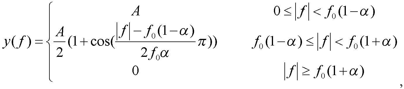
- The method of any one of claims 1 to 17, wherein the first data sequence is generated from a fifth data sequence by a Fourier transform, wherein the fifth data sequence is a time-domain data sequence.
- The method of claim 18, wherein the fifth data sequence is generated from a sixth data sequence, the sixth data sequence is formed by constellation modulation of a seventh data sequence composed of 0 and 1, and constellation modulation of the sixth data sequence is π/2-binary phase-shift keying (π/2-BPSK).
- The method of claim 19, wherein the sixth data sequence is a reference sequence, and constellation modulation of the reference sequence is π/2-BPSK.
- The method of claim 19 or 20, wherein the sixth data sequence contains L pieces of reference sequence data as well as constellation-modulated data, wherein L ≥ 0.
- The method of claim 19 or 20, wherein the fifth data sequence is generated from the sixth data sequence in the following manner:
N pieces of new data are inserted between each two adjacent pieces of data in the sixth data sequence, wherein each of the N pieces of new data is a sum of the two adjacent pieces of data multiplied by
- The method of claim 22, wherein N is 0 or 1.
- The method of claim 19 or 20, wherein the fifth data sequence is generated from the sixth data sequence in the following manner:
N pieces of new data are inserted between each two adjacent pieces of data in the sixth data sequence, wherein a magnitude of each of the N pieces of new data is the same as a magnitude of each of the two adjacent pieces of data, a phase difference between adjacent pieces of data in the sixth data sequence obtained after the N pieces of new data are inserted is
- The method of any one of claims 1 to 17, wherein a length of the first data sequence is the same as a length of the second data sequence.
- The method of any one of claims 1 to 17, before transmitting the fourth data sequence on the physical time-frequency resource, further comprising:
filtering the fourth data sequence. - A data transmission device, comprising:a memory configured to store a program; anda processor configured to execute the program to perform a pointwise multiplication between a first data sequence and a second data sequence to obtain a third data sequence, wherein the first data sequence and the second data sequence are each a frequency-domain data sequence; perform an inverse Fourier transform on the third data sequence to obtain a fourth data sequence; and transmit the fourth data sequence on a physical time-frequency resource.
- A non-volatile storage medium, comprising a stored program which, when executed, causes the data transmission method of any one of claims 1 to 26 to be performed.
Applications Claiming Priority (2)
| Application Number | Priority Date | Filing Date | Title |
|---|---|---|---|
| CN202211080863.5A CN117692291A (en) | 2022-09-05 | 2022-09-05 | Data transmission methods, equipment and storage media |
| PCT/CN2023/099777 WO2024051242A1 (en) | 2022-09-05 | 2023-06-13 | Data transmission method, and device and storage medium |
Publications (1)
| Publication Number | Publication Date |
|---|---|
| EP4572276A1 true EP4572276A1 (en) | 2025-06-18 |
Family
ID=90128847
Family Applications (1)
| Application Number | Title | Priority Date | Filing Date |
|---|---|---|---|
| EP23861945.6A Pending EP4572276A1 (en) | 2022-09-05 | 2023-06-13 | Data transmission method, and device and storage medium |
Country Status (5)
| Country | Link |
|---|---|
| US (1) | US20250274325A1 (en) |
| EP (1) | EP4572276A1 (en) |
| KR (1) | KR20250042830A (en) |
| CN (1) | CN117692291A (en) |
| WO (1) | WO2024051242A1 (en) |
Families Citing this family (2)
| Publication number | Priority date | Publication date | Assignee | Title |
|---|---|---|---|---|
| CN120825381A (en) * | 2024-04-15 | 2025-10-21 | 中兴通讯股份有限公司 | Data modulation and demodulation method, communication device and storage medium |
| CN121356958A (en) * | 2024-07-15 | 2026-01-16 | 中兴通讯股份有限公司 | A data transmission method |
Family Cites Families (6)
| Publication number | Priority date | Publication date | Assignee | Title |
|---|---|---|---|---|
| US11985017B2 (en) * | 2018-10-28 | 2024-05-14 | Indian Institute Of Technology Hyderabad (Iith) | Method and system for generating a transmit waveform for reference sequences |
| CN110191077B (en) * | 2019-06-04 | 2022-01-25 | 广东电网有限责任公司 | Method, device, equipment and storage medium for reducing PAPR |
| WO2021042318A1 (en) * | 2019-09-05 | 2021-03-11 | Zte Corporation | Modulation scheme for low peak average power ratio (papr) |
| WO2021093074A1 (en) * | 2019-12-13 | 2021-05-20 | Zte Corporation | Frequency-domain modulation scheme for low peak average power ratio |
| CN111901279A (en) * | 2020-07-07 | 2020-11-06 | 中兴通讯股份有限公司 | Data transmission method, device, equipment and storage medium |
| CN114070698B (en) * | 2020-08-10 | 2024-06-04 | 华为技术有限公司 | Data sending and receiving method and device |
-
2022
- 2022-09-05 CN CN202211080863.5A patent/CN117692291A/en active Pending
-
2023
- 2023-06-13 US US19/106,467 patent/US20250274325A1/en active Pending
- 2023-06-13 KR KR1020257006750A patent/KR20250042830A/en active Pending
- 2023-06-13 EP EP23861945.6A patent/EP4572276A1/en active Pending
- 2023-06-13 WO PCT/CN2023/099777 patent/WO2024051242A1/en not_active Ceased
Also Published As
| Publication number | Publication date |
|---|---|
| KR20250042830A (en) | 2025-03-27 |
| WO2024051242A1 (en) | 2024-03-14 |
| US20250274325A1 (en) | 2025-08-28 |
| CN117692291A (en) | 2024-03-12 |
Similar Documents
| Publication | Publication Date | Title |
|---|---|---|
| KR102341966B1 (en) | Method and apparatus of transmitting/receiving for reducing peak to average power ratio in an orthogonal frequency division multiplexing system | |
| US10454746B2 (en) | System and method for orthogonal frequency division multiplexing-offset quadrature amplitude modulation | |
| EP3716558A1 (en) | Data transmission method and device | |
| US20140192925A1 (en) | Method of and apparatus for reducing papr in filter-bank multi-carrier system | |
| EP4572276A1 (en) | Data transmission method, and device and storage medium | |
| EP4376369B1 (en) | Sequence-based signal processing method and signal processing apparatus | |
| EP2141878A1 (en) | Method and apparatus for OFDM spectral diversity using guard bands | |
| KR101022753B1 (en) | OPDM system and data transmission method therefor | |
| US7948868B2 (en) | Method and arrangement relating to the insertion of pilot tones in the frequency domain in SC-FDMA | |
| US12218785B2 (en) | Transmitter using symbol constellation rotation and spectrum shaping, transmission method thereof, receiver and reception method thereof in communication system | |
| KR20240005066A (en) | Data transmission methods, devices, electronic equipment and storage media technology fields | |
| CN108900461B (en) | Wireless communication system broadband signal design method based on large-scale MIMO | |
| CN101369998A (en) | A digital peak clipping method and device | |
| Frank et al. | A survey on the envelope fluctuations of DFT precoded OFDMA signals | |
| US8406320B2 (en) | Digital clipping method for a transmitter of an orthogonal frequency division multiple access system | |
| Mizutani et al. | A low-pass filtered time-domain window for DFTs-OFDM to reduce out-of-band emission with low complexity | |
| CN101359984A (en) | Method, device and system for realizing signal transmission | |
| Montalvo et al. | Comparison and analysis of PAPR reduction techniques in OFDMA and SC-FDMA systems | |
| EP2424182A1 (en) | PAPR improvement in SC-FDMA by extending bandwidth and spectral shaping | |
| CN101729466A (en) | Device and method for detecting and using blank frequency spectrum with peak interference | |
| CN115941414B (en) | Method, device and storage medium for reducing peak-to-average ratio of OFDM (orthogonal frequency division multiplexing) signal | |
| EP4521693A1 (en) | Data modulation method and apparatus, and medium and storage medium | |
| Hasan et al. | Performance Evaluation of OFDM vs FBMC in Impulsive Noise Channel | |
| Daoud et al. | OFDM systems performance enhancement | |
| JP2026500060A (en) | OFDM signal processing method, transmission system and device |
Legal Events
| Date | Code | Title | Description |
|---|---|---|---|
| STAA | Information on the status of an ep patent application or granted ep patent |
Free format text: STATUS: THE INTERNATIONAL PUBLICATION HAS BEEN MADE |
|
| PUAI | Public reference made under article 153(3) epc to a published international application that has entered the european phase |
Free format text: ORIGINAL CODE: 0009012 |
|
| STAA | Information on the status of an ep patent application or granted ep patent |
Free format text: STATUS: REQUEST FOR EXAMINATION WAS MADE |
|
| 17P | Request for examination filed |
Effective date: 20250310 |
|
| AK | Designated contracting states |
Kind code of ref document: A1 Designated state(s): AL AT BE BG CH CY CZ DE DK EE ES FI FR GB GR HR HU IE IS IT LI LT LU LV MC ME MK MT NL NO PL PT RO RS SE SI SK SM TR |
|
| DAV | Request for validation of the european patent (deleted) | ||
| DAX | Request for extension of the european patent (deleted) |