EP4572118A1 - Electric device - Google Patents
Electric device Download PDFInfo
- Publication number
- EP4572118A1 EP4572118A1 EP23874526.9A EP23874526A EP4572118A1 EP 4572118 A1 EP4572118 A1 EP 4572118A1 EP 23874526 A EP23874526 A EP 23874526A EP 4572118 A1 EP4572118 A1 EP 4572118A1
- Authority
- EP
- European Patent Office
- Prior art keywords
- internal space
- electrical apparatus
- electrical
- outside frame
- electrical component
- Prior art date
- Legal status (The legal status is an assumption and is not a legal conclusion. Google has not performed a legal analysis and makes no representation as to the accuracy of the status listed.)
- Pending
Links
Images


Classifications
-
- H—ELECTRICITY
- H10—SEMICONDUCTOR DEVICES; ELECTRIC SOLID-STATE DEVICES NOT OTHERWISE PROVIDED FOR
- H10W—GENERIC PACKAGES, INTERCONNECTIONS, CONNECTORS OR OTHER CONSTRUCTIONAL DETAILS OF DEVICES COVERED BY CLASS H10
- H10W76/00—Containers; Fillings or auxiliary members therefor; Seals
- H10W76/40—Fillings or auxiliary members in containers, e.g. centering rings
- H10W76/42—Fillings
- H10W76/43—Gaseous fillings
-
- H—ELECTRICITY
- H05—ELECTRIC TECHNIQUES NOT OTHERWISE PROVIDED FOR
- H05K—PRINTED CIRCUITS; CASINGS OR CONSTRUCTIONAL DETAILS OF ELECTRIC APPARATUS; MANUFACTURE OF ASSEMBLAGES OF ELECTRICAL COMPONENTS
- H05K7/00—Constructional details common to different types of electric apparatus
- H05K7/20—Modifications to facilitate cooling, ventilating, or heating
- H05K7/2089—Modifications to facilitate cooling, ventilating, or heating for power electronics, e.g. for inverters for controlling motor
- H05K7/20927—Liquid coolant without phase change
-
- H—ELECTRICITY
- H10—SEMICONDUCTOR DEVICES; ELECTRIC SOLID-STATE DEVICES NOT OTHERWISE PROVIDED FOR
- H10W—GENERIC PACKAGES, INTERCONNECTIONS, CONNECTORS OR OTHER CONSTRUCTIONAL DETAILS OF DEVICES COVERED BY CLASS H10
- H10W40/00—Arrangements for thermal protection or thermal control
- H10W40/40—Arrangements for thermal protection or thermal control involving heat exchange by flowing fluids
- H10W40/47—Arrangements for thermal protection or thermal control involving heat exchange by flowing fluids by flowing liquids, e.g. forced water cooling
-
- H—ELECTRICITY
- H10—SEMICONDUCTOR DEVICES; ELECTRIC SOLID-STATE DEVICES NOT OTHERWISE PROVIDED FOR
- H10W—GENERIC PACKAGES, INTERCONNECTIONS, CONNECTORS OR OTHER CONSTRUCTIONAL DETAILS OF DEVICES COVERED BY CLASS H10
- H10W42/00—Arrangements for protection of devices
-
- H—ELECTRICITY
- H10—SEMICONDUCTOR DEVICES; ELECTRIC SOLID-STATE DEVICES NOT OTHERWISE PROVIDED FOR
- H10W—GENERIC PACKAGES, INTERCONNECTIONS, CONNECTORS OR OTHER CONSTRUCTIONAL DETAILS OF DEVICES COVERED BY CLASS H10
- H10W76/00—Containers; Fillings or auxiliary members therefor; Seals
- H10W76/10—Containers or parts thereof
- H10W76/12—Containers or parts thereof characterised by their shape
-
- H—ELECTRICITY
- H02—GENERATION; CONVERSION OR DISTRIBUTION OF ELECTRIC POWER
- H02M—APPARATUS FOR CONVERSION BETWEEN AC AND AC, BETWEEN AC AND DC, OR BETWEEN DC AND DC, AND FOR USE WITH MAINS OR SIMILAR POWER SUPPLY SYSTEMS; CONVERSION OF DC OR AC INPUT POWER INTO SURGE OUTPUT POWER; CONTROL OR REGULATION THEREOF
- H02M3/00—Conversion of DC power input into DC power output
- H02M3/003—Constructional details, e.g. physical layout, assembly, wiring or busbar connections
-
- H—ELECTRICITY
- H02—GENERATION; CONVERSION OR DISTRIBUTION OF ELECTRIC POWER
- H02M—APPARATUS FOR CONVERSION BETWEEN AC AND AC, BETWEEN AC AND DC, OR BETWEEN DC AND DC, AND FOR USE WITH MAINS OR SIMILAR POWER SUPPLY SYSTEMS; CONVERSION OF DC OR AC INPUT POWER INTO SURGE OUTPUT POWER; CONTROL OR REGULATION THEREOF
- H02M7/00—Conversion of AC power input into DC power output; Conversion of DC power input into AC power output
- H02M7/003—Constructional details, e.g. physical layout, assembly, wiring or busbar connections
Definitions
- the present disclosure relates to an electrical apparatus.
- power electronics apparatuses have been studied in all engine-driven mobility products, and improvement of power density thereof has been required. Accordingly, power electronics apparatuses are required to be applicable to any climate in the world. In aircraft, environmental resistance capable of coping with a sudden change in altitude is essential. At the same time, improvement in cooling performance, increase in voltage, weight reduction, and the like are required, and technology development for this purpose is in progress.
- PTL 1 discloses the air conditioner including an inverter device that drives an electric compressor.
- T inverter device has a condensation prevention structure of its case that accommodates a power element and a control circuit that controls the power element.
- the case is filled with an inert gas.
- PTL 1 describes that the case is filled with the inert gas at room temperature and at a pressure slightly higher than atmospheric pressure.
- PTL 2 discloses a power conversion device for an aircraft.
- the power conversion deice includes a sealed casing including a gas inlet valve and a gas outlet valve, a power semiconductor module disposed in an internal space of the sealed casing, and a dry gas filling the internal space of the sealed casing.
- PTL 2 further discloses that a dry gas is injected from ambient pressure (for example, atmospheric pressure) outside the sealed casing, and thus the internal space of the sealed casing has a set pressure.
- PTL 1 and PTL 2 disclose means that sets the air pressure in a container in which an electrical component is disposed to be higher than the atmospheric pressure. However, depending on the types of electrical components, some electrical components are damaged when the air pressure becomes high.
- An object of the present disclosure is to prevent condensation from occurring on a wall surface or the like of an sealed space and to prevent damage of an electrical component due to atmospheric pressure in an electrical apparatus in which an electrical component such as an electrolytic capacitor is disposed in the sealed space.
- An electrical apparatus of the present disclosure includes an electrical component, an electrical component support unit, and an outside frame. Between the electrical component support unit and the outer frame an internal space is provided, and the electrical component is installed in the internal space.
- the internal space contains a sealed gas having a water vapor pressure of 0.60 kPa or less.
- condensation can be prevent from occurring on a wall surface or the like of the sealed space, and damage of the electrical component due to atmospheric pressure can be prevented.
- an electrical apparatus and an electronic apparatus that function using electricity as an energy source are generally referred to as an "electrical apparatus".
- the electrical apparatus also include a power conversion device.
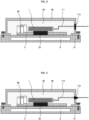
- FIG. 1 is a schematic cross-sectional view illustrating an electrical apparatus according to a first embodiment.
- the electrical apparatus illustrated in this drawing is a power conversion device having a liquid cooling mechanism.
- the power conversion device includes a switching element 1, an electrolytic capacitor 60, a substrate 2, a substrate support unit 21, a heat conducting member 22, and outside frame 90.
- a liquid flow channel 8 is provided in the substrate support unit 21.
- the substrate 2 and the heat conducting member 22 are disposed in the substrate support unit 21.
- the switching element 1 is disposed to be in contact with the heat conducting member 22.
- the electrolytic capacitor 60 is disposed on the substrate 2.
- the outside frame 90 is fixed to the substrate support unit 21 to cover the switching element 1, the electrolytic capacitor 60, the substrate 2, and heat conducting member 22. As a result, an internal space 92 is formed between the substrate support unit 21 and the outside frame 90. The internal space 92 is completely sealed so that no air enters from or exits to the outside.
- the switching element 1, the electrolytic capacitor 60, the substrate 2, and the heat conducting member 22 are configured not to be in contact with the outside frame 90.
- a gas that does not substantially contain water vapor, such as dry air, is sealed into the internal space 92. Accordingly, condensation does not occur on the inner wall surface of the outside frame 90.
- the water vapor pressure of the gas sealed into the internal space 92 is desirably 0.60 kPa or less, more desirably 0.080 kPa or less, and particularly desirably 0.0020 kPa or less.
- the dry air has the same composition (it contains about 78 volume percent of nitrogen and about 21 volume percent of oxygen as main components) as that of normal air.
- the switching element 1 includes a metal-oxide-semiconductor field-effect transistor (MOSFET) or a power module.
- the substrate support unit 21 is made of metal. Note that, in this specification, components, such as the switching element 1, that function by energization are collectively referred to as "electrical components".
- the electrical component includes a capacitor, a printed circuit board (PCB), and the like.
- the outside frame 90 is made of metal such as aluminum alloy or stainless steel, and has strength as a cover of the switching element 1.
- the thickness of the outside frame 90 is desirably about 2 to 3 mm although it depends on the material.
- outside frame 90 is made of metal, even if a lightning strike occurs, a noise current is less likely to occur inside the power conversion device, and malfunction can be less likely to occur.
- a contact area between the substrate support unit 21 and the heat conducting member 22, and a contact area between the switching element 1 and the heat conducting member 22 are enough wide so that heat generated in the switching element 1 is sufficiently removed.
- the liquid flow channel 8 of the substrate support unit 21 is disposed so that the liquid flowing through the liquid flow channel 8 can sufficiently remove heat from the heat conducting member 22.
- the liquid flowing through the liquid flow channel 8 include water, mineral oil, fluorocarbon coolant, and vegetable oil. Note that, in this specification, cooling of the power conversion device and the like with the liquid flowing through the liquid flow channel 8 is described, but a cooling mechanism of the electrical apparatus of the present disclosure is not limited thereto.
- the cooling mechanism may be achieved by a gas such as air, a refrigerant with a phase change, or the like. Specifically, the cooling mechanism may be achieved by forced-air cooling or by using a heat pipe
- the electrolytic capacitor 60 is used for smoothing and filtering in the power conversion device.
- a capacitor a ceramic capacitor, a film capacitor, a hybrid capacitor, or the like is also used.
- Capacitors other than those exemplified here may be used, and the type thereof is not limited.
- a valve may be provided in the electrolytic capacitor 60 to prevent damage due to an increase in atmospheric pressure.
- the operation of the valve of the electrolytic capacitor 60 may be hindered when the pressure of the gas in the internal space 92 of the sealed power conversion device increases due to a temperature rise or the like caused by the operation. Therefore, in a state where the power conversion device is not energized, in other words, in a state where heat is not generated and the temperature is not high in the power conversion device, it is desirable to finely adjust the air pressure of the internal space 92 to be less than the atmospheric pressure. That is, when the power conversion device is not operated, it is desirable to set the initial pressure of the internal space 92 to a slightly negative pressure.
- the substrate support unit 21 having the liquid flow channel 8 is desirably set to have the ground potential.
- the substrate support unit 21 is desirably made of metal such as aluminum alloy, stainless steel, or copper alloy.
- a portion with high electrical stress, such as the periphery of the switching element 1 is desirably covered with a solid insulating material such as silicone.
- a solid insulating material such as silicone.
- PPS polyphenylene sulfide resin
- an epoxy resin an unsaturated polyester, and the like are suitable as the solid insulating material.
- the gas sealed in the internal space 92 may be nitrogen, argon, carbon dioxide, nitrogen dioxide, or the like, in addition to dry air. Desirably, the gas is not liquefied even at -70°C. Further, these gases may be mixed and sealed.
- the gas sealed into the internal space 92 one obtained by adding oxygen to dry air to make the oxygen concentration higher than the atmospheric air (oxygen concentration: 21 volume percent) may be used.
- oxygen concentration 21 volume percent
- the gas having such high electron adhesiveness carbon dioxide, sulfur hexafluoride, carbon monoxide, or the like may be used in addition to oxygen.
- a halogen series-containing gas or the like may be mixed.
- halogen series-containing gas containing fluorine, chlorine, iodine, or the like a fluorinated gas, such as BF 3 or CF 4 , a chloride gas, a Freon gas, or the like is known.
- the internal space 92 may be depressurized to be in a vacuum state. In this case, it is more desirable as the degree of vacuum is higher, but specifically, 1 Pa or less is desirable, and 0.1 Pa or less is more desirable.
- the water vapor pressure is also reduced, so that condensation and the like can be prevented.
- FIG. 2 is a schematic cross-sectional view illustrating an electrical apparatus according to the second embodiment.
- a low-pressure chamber 100 is provided between the substrate support unit 21 and the outside frame 90.
- the internal space 92 and the low-pressure chamber 100 are separated from each other by a partition plate 101.
- a vent filter 99 is provided in the partition plate 101.
- the electrical component is installed in the internal space 92.
- the air pressure is set to be lower in the low-pressure chamber 100 than in the internal space 92.
- the vent filter 99 is opened and the gas in the internal space 92 can be allowed to flow out to the low-pressure chamber 100.
- the air pressure of the internal space 92 can be made higher than the atmospheric pressure (1 atm).
- FIG. 3 is a schematic cross-sectional view illustrating an electrical apparatus according to the third embodiment.
- the switching element 1 is electrically connected to the outside via a cable 111.
- the cable 111 is obtained by covering conductors.
- An extract port of the cable 111 provided in the outside frame 90 is sealed by a silicone FIPG 112 or the like to secure airtightness of the internal space 92.
- FIPG is an abbreviation of Formed In Place Gasket.
- FIG. 4 is a schematic cross-sectional view illustrating an electrical apparatus according to the fourth embodiment.
- the switching element 1 is electrically connected to the outside via a bus bar 115.
- a cable may be used instead of the bus bar 115.
- the cable is obtained by covering conductors.
- a connecting portion of the bus bar 115 provided in the outside frame 90 is a Bayonet Neill-Concelman (BNC) connector 116. Accordingly, airtightness of the internal space 92 is ensured. Further, connection work can be facilitated.
- BNC Bayonet Neill-Concelman
- FIG. 5 is a schematic cross-sectional view illustrating an electrical apparatus according to the fifth embodiment.
- a frame in which an outer wall surface of a flame-retardant resin frame 130 is covered with a metal film 131 is used instead of the outside frame 90 (made of metal) of FIG. 1 .
- This frame is also referred to as an "outside frame".
- the metal film 131 is preferably made of aluminum, iron, nickel, or the like.
- the metal film 131 may also be provided on the inner wall surface of the flame-retardant resin frame 130.
- Such a configuration makes it possible to prevent ignition at the time of a lightning strike, inflow of a noise, and the like. Further, the weight of the electrical apparatus can be reduced.
- Suitable examples of a material of the flame-retardant resin frame 130 are a foamed resin such as polyurethane, polystyrene, polyethylene, polypropylene, or silicone. Further, a vacuum heat insulating material or the like using glass wool, silica powder, or the like as a core material is also desirable. Note that the material of the flame-retardant resin frame 130 is not limited to them.
- a metal frame may be used instead of the flame-retardant resin frame 130.
- the electrical apparatus includes the substrate 2, the substrate support unit 21, and the heat conducting member 22.
- the electrical apparatus of the present disclosure may not necessarily include these components, and may include a member that supports the electrical components, instead of the substrate support unit 21.
- the internal space may be formed between this member and the outside frame 90.
- the substrate support unit 21 and the member are collectively referred to as the "electrical component support unit”.
- the electrical apparatus of the present disclosure is also applicable to general mobilities, such as aircraft, transportation equipment, construction machine, and the like.
- the electrical component includes an electrolytic capacitor.
- the air pressure in the internal space is set to be lower than the atmospheric pressure.
- the gas in the internal space is dry air, nitrogen, argon, carbon dioxide, nitrogen dioxide, or a mixture of any two or more of them.
- the internal space is in a vacuum state.
- the outside frame contains at least any one of polyurethane, polystyrene, polyethylene, polypropylene, and silicone, and is configured by covering any one of them with a metal film.
- the outside frame includes a vacuum heat insulating material containing at least any one of glass wool and silica powder as a core material.
- the oxygen concentration of the gas in the internal space is higher than 21 volume percent.
- the gas in the internal space contains at least any one of carbon dioxide, sulfur hexafluoride, carbon monoxide, and a halogen series-containing gas.
- the low-pressure chamber adjacent to the internal space is provided between the electrical component support unit and the outside frame, and the air pressure is set to be lower in the low-pressure chamber than in the internal space.
- the vent filter is provided between the internal space and the low-pressure chamber.
- the electrical component is electrically connected to the outside via the cable, and the extraction port of the cable provided in the outside frame is sealed with silicone FIPG.
- the electrical component is electrically connected to the outside via the cable or the buss bar, and a BNC connector is provided at the extraction port of the cable or the connecting portion of the bus bar provided in the outside frame.
Landscapes
- Engineering & Computer Science (AREA)
- Microelectronics & Electronic Packaging (AREA)
- Physics & Mathematics (AREA)
- Thermal Sciences (AREA)
- Inverter Devices (AREA)
Abstract
This electric device comprises electrical components (1, 60), an electrical component support unit (21), and an outside frame (90). An interior space (92) is formed between the electrical component support unit and the outside frame, the electrical components are installed in the internal space, and gas is enclosed in the internal space at a water vapor pressure of 0.60 Pa or less. In electric devices in which electrical components such as electrolytic capacitors (60), etc., are disposed in a closed space, this makes it possible to prevent the occurrence of condensation on the wall surfaces, etc., of the closed space, and to prevent damage to the electrical components due to air pressure.
Description
- The present disclosure relates to an electrical apparatus.
- In order to achieve zero-carbon society, CO2 emission control is strongly demanded in each country, and motorization of a power system is actively promoted as a substitute for an engine using fossil fuel.
- Application of power electronics apparatuses has been studied in all engine-driven mobility products, and improvement of power density thereof has been required. Accordingly, power electronics apparatuses are required to be applicable to any climate in the world. In aircraft, environmental resistance capable of coping with a sudden change in altitude is essential. At the same time, improvement in cooling performance, increase in voltage, weight reduction, and the like are required, and technology development for this purpose is in progress.
-
PTL 1 discloses the air conditioner including an inverter device that drives an electric compressor. T inverter device has a condensation prevention structure of its case that accommodates a power element and a control circuit that controls the power element. The case is filled with an inert gas.PTL 1 describes that the case is filled with the inert gas at room temperature and at a pressure slightly higher than atmospheric pressure. -
PTL 2 discloses a power conversion device for an aircraft. The power conversion deice includes a sealed casing including a gas inlet valve and a gas outlet valve, a power semiconductor module disposed in an internal space of the sealed casing, and a dry gas filling the internal space of the sealed casing.PTL 2 further discloses that a dry gas is injected from ambient pressure (for example, atmospheric pressure) outside the sealed casing, and thus the internal space of the sealed casing has a set pressure. -
- PTL 1:
JP 2004-219031 A - PTL 2:
JP Patent No. 6878712 -
PTL 1 andPTL 2 disclose means that sets the air pressure in a container in which an electrical component is disposed to be higher than the atmospheric pressure. However, depending on the types of electrical components, some electrical components are damaged when the air pressure becomes high. - An object of the present disclosure is to prevent condensation from occurring on a wall surface or the like of an sealed space and to prevent damage of an electrical component due to atmospheric pressure in an electrical apparatus in which an electrical component such as an electrolytic capacitor is disposed in the sealed space.
- An electrical apparatus of the present disclosure includes an electrical component, an electrical component support unit, and an outside frame. Between the electrical component support unit and the outer frame an internal space is provided, and the electrical component is installed in the internal space. The internal space contains a sealed gas having a water vapor pressure of 0.60 kPa or less.
- According to the present disclosure, in the electrical apparatus in which the electrical component such as the electrolytic capacitor is disposed in the sealed space, condensation can be prevent from occurring on a wall surface or the like of the sealed space, and damage of the electrical component due to atmospheric pressure can be prevented.
-
- [
FIG. 1] FIG. 1 is a schematic cross-sectional view illustrating an electrical apparatus according to a first embodiment. - [
FIG. 2] FIG. 2 is a schematic cross-sectional view illustrating an electrical apparatus according to a second embodiment. - [
FIG. 3] FIG. 3 is a schematic cross-sectional view illustrating an electrical apparatus according to a third embodiment. - [
FIG. 4] FIG. 4 is a schematic cross-sectional view illustrating an electrical apparatus according to a fourth embodiment. - [
FIG. 5] FIG. 5 is a schematic cross-sectional view illustrating an electrical apparatus according to a fifth embodiment. - Hereinafter, embodiments of the present disclosure will be described in detail with reference to the drawings.
- Note that, in this specification, an electrical apparatus and an electronic apparatus that function using electricity as an energy source are generally referred to as an "electrical apparatus". The electrical apparatus also include a power conversion device.
-
FIG. 1 is a schematic cross-sectional view illustrating an electrical apparatus according to a first embodiment. - The electrical apparatus illustrated in this drawing is a power conversion device having a liquid cooling mechanism. The power conversion device includes a
switching element 1, anelectrolytic capacitor 60, asubstrate 2, asubstrate support unit 21, aheat conducting member 22, andoutside frame 90. - A
liquid flow channel 8 is provided in thesubstrate support unit 21. Thesubstrate 2 and theheat conducting member 22 are disposed in thesubstrate support unit 21. Theswitching element 1 is disposed to be in contact with theheat conducting member 22. Theelectrolytic capacitor 60 is disposed on thesubstrate 2. - The
outside frame 90 is fixed to thesubstrate support unit 21 to cover theswitching element 1, theelectrolytic capacitor 60, thesubstrate 2, andheat conducting member 22. As a result, aninternal space 92 is formed between thesubstrate support unit 21 and theoutside frame 90. Theinternal space 92 is completely sealed so that no air enters from or exits to the outside. Theswitching element 1, theelectrolytic capacitor 60, thesubstrate 2, and theheat conducting member 22 are configured not to be in contact with theoutside frame 90. A gas that does not substantially contain water vapor, such as dry air, is sealed into theinternal space 92. Accordingly, condensation does not occur on the inner wall surface of theoutside frame 90. The water vapor pressure of the gas sealed into theinternal space 92 is desirably 0.60 kPa or less, more desirably 0.080 kPa or less, and particularly desirably 0.0020 kPa or less. Here, the dry air has the same composition (it contains about 78 volume percent of nitrogen and about 21 volume percent of oxygen as main components) as that of normal air. - The
switching element 1 includes a metal-oxide-semiconductor field-effect transistor (MOSFET) or a power module. Thesubstrate support unit 21 is made of metal. Note that, in this specification, components, such as theswitching element 1, that function by energization are collectively referred to as "electrical components". The electrical component includes a capacitor, a printed circuit board (PCB), and the like. - The
outside frame 90 is made of metal such as aluminum alloy or stainless steel, and has strength as a cover of theswitching element 1. The thickness of theoutside frame 90 is desirably about 2 to 3 mm although it depends on the material. - Further, since the
outside frame 90 is made of metal, even if a lightning strike occurs, a noise current is less likely to occur inside the power conversion device, and malfunction can be less likely to occur. - It is desirable that a contact area between the
substrate support unit 21 and theheat conducting member 22, and a contact area between theswitching element 1 and theheat conducting member 22 are enough wide so that heat generated in theswitching element 1 is sufficiently removed. In addition, it is desirable that theliquid flow channel 8 of thesubstrate support unit 21 is disposed so that the liquid flowing through theliquid flow channel 8 can sufficiently remove heat from theheat conducting member 22. Examples of the liquid flowing through theliquid flow channel 8 include water, mineral oil, fluorocarbon coolant, and vegetable oil. Note that, in this specification, cooling of the power conversion device and the like with the liquid flowing through theliquid flow channel 8 is described, but a cooling mechanism of the electrical apparatus of the present disclosure is not limited thereto. The cooling mechanism may be achieved by a gas such as air, a refrigerant with a phase change, or the like. Specifically, the cooling mechanism may be achieved by forced-air cooling or by using a heat pipe - The
electrolytic capacitor 60 is used for smoothing and filtering in the power conversion device. As such a capacitor, a ceramic capacitor, a film capacitor, a hybrid capacitor, or the like is also used. Capacitors other than those exemplified here may be used, and the type thereof is not limited. - In the case of the
electrolytic capacitor 60, a valve may be provided in theelectrolytic capacitor 60 to prevent damage due to an increase in atmospheric pressure. In this case, the operation of the valve of theelectrolytic capacitor 60 may be hindered when the pressure of the gas in theinternal space 92 of the sealed power conversion device increases due to a temperature rise or the like caused by the operation. Therefore, in a state where the power conversion device is not energized, in other words, in a state where heat is not generated and the temperature is not high in the power conversion device, it is desirable to finely adjust the air pressure of theinternal space 92 to be less than the atmospheric pressure. That is, when the power conversion device is not operated, it is desirable to set the initial pressure of theinternal space 92 to a slightly negative pressure. - As for electrical components other than the
electrolytic capacitor 60, by setting theinternal space 92 to have a negative pressure, pressure rise during operation can be offset, and damage of each electrical component can be prevented. - The
substrate support unit 21 having theliquid flow channel 8 is desirably set to have the ground potential. Thesubstrate support unit 21 is desirably made of metal such as aluminum alloy, stainless steel, or copper alloy. - Under the low atmospheric pressure environment, a partial discharge inception voltage greatly decreases as compared with under the atmospheric pressure. Therefore, it is necessary to apply a solid or liquid having a partial discharge inception voltage about 10 times higher than that of air on the surface to which the voltage is applied and the surface to be grounded.
- In a case where partial discharge inception is feared due to high voltage, high electric field stress, or the like, for example, a portion with high electrical stress, such as the periphery of the
switching element 1 is desirably covered with a solid insulating material such as silicone. This makes it possible to make partial discharge under low atmospheric pressure less likely to occur. In addition, a polyphenylene sulfide resin (PPS), an epoxy resin, an unsaturated polyester, and the like are suitable as the solid insulating material. - The gas sealed in the
internal space 92 may be nitrogen, argon, carbon dioxide, nitrogen dioxide, or the like, in addition to dry air. Desirably, the gas is not liquefied even at -70°C. Further, these gases may be mixed and sealed. - Furthermore, as the gas sealed into the
internal space 92, one obtained by adding oxygen to dry air to make the oxygen concentration higher than the atmospheric air (oxygen concentration: 21 volume percent) may be used. By increasing the oxygen concentration, electron adhesiveness of a gas to be sealed is increased, discharge is easily suppressed, and insulation is improved. As the gas having such high electron adhesiveness, carbon dioxide, sulfur hexafluoride, carbon monoxide, or the like may be used in addition to oxygen. In addition to the sulfur hexafluoride described above, a halogen series-containing gas or the like may be mixed. As the halogen series-containing gas containing fluorine, chlorine, iodine, or the like, a fluorinated gas, such as BF3 or CF4, a chloride gas, a Freon gas, or the like is known. - Further, the
internal space 92 may be depressurized to be in a vacuum state. In this case, it is more desirable as the degree of vacuum is higher, but specifically, 1 Pa or less is desirable, and 0.1 Pa or less is more desirable. By bringing theinternal space 92 into a vacuum state, the water vapor pressure is also reduced, so that condensation and the like can be prevented. In addition, it is possible to prevent corrosion due to condensation, malfunction due to the lightning surge, and the like. - In the present embodiment, only a part of the configuration different from that in the first embodiment will be described.
-
FIG. 2 is a schematic cross-sectional view illustrating an electrical apparatus according to the second embodiment. - In the drawing, in addition to the
internal space 92, a low-pressure chamber 100 is provided between thesubstrate support unit 21 and theoutside frame 90. Theinternal space 92 and the low-pressure chamber 100 are separated from each other by apartition plate 101. Avent filter 99 is provided in thepartition plate 101. - The electrical component is installed in the
internal space 92. The air pressure is set to be lower in the low-pressure chamber 100 than in theinternal space 92. With such a configuration, in a case where the air pressure in theinternal space 92 increases due to the heat generation in the electrical components, thevent filter 99 is opened and the gas in theinternal space 92 can be allowed to flow out to the low-pressure chamber 100. In this case, in the initial state, the air pressure of theinternal space 92 can be made higher than the atmospheric pressure (1 atm). - In the present embodiment, only a part of the configuration different from that in the first embodiment will be described.
-
FIG. 3 is a schematic cross-sectional view illustrating an electrical apparatus according to the third embodiment. - In the drawing, the switching
element 1 is electrically connected to the outside via acable 111. Thecable 111 is obtained by covering conductors. An extract port of thecable 111 provided in theoutside frame 90 is sealed by asilicone FIPG 112 or the like to secure airtightness of theinternal space 92. Here, FIPG is an abbreviation of Formed In Place Gasket. - In the present embodiment, only a part of the configuration different from that in the third embodiment will be described.
-
FIG. 4 is a schematic cross-sectional view illustrating an electrical apparatus according to the fourth embodiment. - In the drawing, the switching
element 1 is electrically connected to the outside via abus bar 115. A cable may be used instead of thebus bar 115. The cable is obtained by covering conductors. - A connecting portion of the
bus bar 115 provided in theoutside frame 90 is a Bayonet Neill-Concelman (BNC)connector 116. Accordingly, airtightness of theinternal space 92 is ensured. Further, connection work can be facilitated. - In the present embodiment, only a part of the configuration different from that in the first embodiment will be described.
-
FIG. 5 is a schematic cross-sectional view illustrating an electrical apparatus according to the fifth embodiment. - In this drawing, a frame in which an outer wall surface of a flame-
retardant resin frame 130 is covered with ametal film 131 is used instead of the outside frame 90 (made of metal) ofFIG. 1 . This frame is also referred to as an "outside frame". Themetal film 131 is preferably made of aluminum, iron, nickel, or the like. Themetal film 131 may also be provided on the inner wall surface of the flame-retardant resin frame 130. Such a configuration makes it possible to prevent ignition at the time of a lightning strike, inflow of a noise, and the like. Further, the weight of the electrical apparatus can be reduced. - Suitable examples of a material of the flame-
retardant resin frame 130 are a foamed resin such as polyurethane, polystyrene, polyethylene, polypropylene, or silicone. Further, a vacuum heat insulating material or the like using glass wool, silica powder, or the like as a core material is also desirable. Note that the material of the flame-retardant resin frame 130 is not limited to them. - Instead of the flame-
retardant resin frame 130, a metal frame may be used. - In the above embodiment, the electrical apparatus includes the
substrate 2, thesubstrate support unit 21, and theheat conducting member 22. However, the electrical apparatus of the present disclosure may not necessarily include these components, and may include a member that supports the electrical components, instead of thesubstrate support unit 21. The internal space may be formed between this member and theoutside frame 90. In this specification, thesubstrate support unit 21 and the member are collectively referred to as the "electrical component support unit". - Note that the electrical apparatus of the present disclosure is also applicable to general mobilities, such as aircraft, transportation equipment, construction machine, and the like.
- Desirable embodiments of the electrical apparatus of the present disclosure will be collectively described below.
- The electrical component includes an electrolytic capacitor.
- The air pressure in the internal space is set to be lower than the atmospheric pressure.
- The gas in the internal space is dry air, nitrogen, argon, carbon dioxide, nitrogen dioxide, or a mixture of any two or more of them.
- The internal space is in a vacuum state.
- The outside frame contains at least any one of polyurethane, polystyrene, polyethylene, polypropylene, and silicone, and is configured by covering any one of them with a metal film.
- The outside frame includes a vacuum heat insulating material containing at least any one of glass wool and silica powder as a core material.
- The oxygen concentration of the gas in the internal space is higher than 21 volume percent.
- The gas in the internal space contains at least any one of carbon dioxide, sulfur hexafluoride, carbon monoxide, and a halogen series-containing gas.
- The low-pressure chamber adjacent to the internal space is provided between the electrical component support unit and the outside frame, and the air pressure is set to be lower in the low-pressure chamber than in the internal space. The vent filter is provided between the internal space and the low-pressure chamber.
- The electrical component is electrically connected to the outside via the cable, and the extraction port of the cable provided in the outside frame is sealed with silicone FIPG.
- The electrical component is electrically connected to the outside via the cable or the buss bar, and a BNC connector is provided at the extraction port of the cable or the connecting portion of the bus bar provided in the outside frame.
-
- 1
- switching element
- 2
- substrate
- 8
- liquid flow channel
- 21
- substrate support unit
- 22
- heat conducting member
- 60
- electrolytic capacitor
- 90
- outside frame
- 92
- internal space
- 99
- vent filter
- 100
- low-pressure chamber
- 101
- partition plate
- 111
- cable
- 112
- silicone FIPG
- 115
- bus bar
- 116
- BNC connector
- 130
- flame-retardant resin frame
- 131
- metal film
Claims (13)
- An electrical apparatus, comprising:an electrical component;an electrical component support unit; andan outside frame,wherein between the electrical component support unit and the outside frame, an internal space is provided,wherein the electrical component is installed in the internal space, andwherein in the internal space a gas having a water vapor pressure of 0.60 kPa or less is sealed.
- The electrical apparatus according to claim 1, wherein the electrical component includes an electrolytic capacitor.
- The electrical apparatus according to claim 1, wherein the internal space has an air pressure set to be less than an atmospheric pressure.
- The electrical apparatus according to claim 1, wherein the gas includes dry air, nitrogen, argon, carbon dioxide, nitrogen dioxide, or a mixture of at least any two kinds of them.
- The electrical apparatus according to claim 1, wherein the internal space is in a vacuum state.
- The electrical apparatus according to claim 1, wherein the outside frame includes at least any one of polyurethane, polystyrene, polyethylene, polypropylene, and silicone, and is configured by covering at least any one of them with a metal film.
- The electrical apparatus according to claim 1, wherein the outside frame includes a vacuum heat insulating material containing at least any one of glass wool and silica powder as a core material.
- The electrical apparatus according to claim 1, wherein the gas has an oxygen concentration higher than 21 volume percent.
- The electrical apparatus according to claim 1, wherein the gas contains at least any one of carbon dioxide, sulfur hexafluoride, carbon monoxide, and a halogen series-containing gas.
- The electrical apparatus according to claim 1,wherein between the electrical component support unit and the outside frame, a low-pressure chamber adjacent to the internal space is provided,wherein the low-pressure chamber has an air pressure set to be lower than that in the internal space, andwherein between the internal space and the low-pressure chamber, a vent filter is provided.
- The electrical apparatus according to claim 1,wherein the electrical component is electrically connected to an outside via a cable, andwherein the outside frame is provided with an extraction port of the cable, the extraction port being sealed with silicone Formed In Place Gasket (FIPG).
- The electrical apparatus according to claim 1,wherein the electrical component is electrically connected to an outside via a cable or a bus bar, andwherein the outside frame is provided with an extraction port of the cable or a connecting portion of the bus bar, the extraction port or the connecting portion being provided with a Bayonet Neill-Concelman (BNC) connector.
- The electrical apparatus according to claim 1, including a power conversion device.
Applications Claiming Priority (2)
| Application Number | Priority Date | Filing Date | Title |
|---|---|---|---|
| JP2022161663A JP2024055060A (en) | 2022-10-06 | 2022-10-06 | Electrical Equipment |
| PCT/JP2023/029046 WO2024075393A1 (en) | 2022-10-06 | 2023-08-09 | Electric device |
Publications (1)
| Publication Number | Publication Date |
|---|---|
| EP4572118A1 true EP4572118A1 (en) | 2025-06-18 |
Family
ID=90607959
Family Applications (1)
| Application Number | Title | Priority Date | Filing Date |
|---|---|---|---|
| EP23874526.9A Pending EP4572118A1 (en) | 2022-10-06 | 2023-08-09 | Electric device |
Country Status (4)
| Country | Link |
|---|---|
| EP (1) | EP4572118A1 (en) |
| JP (1) | JP2024055060A (en) |
| CN (1) | CN119866595A (en) |
| WO (1) | WO2024075393A1 (en) |
Family Cites Families (5)
| Publication number | Priority date | Publication date | Assignee | Title |
|---|---|---|---|---|
| JPS61150608A (en) * | 1984-12-25 | 1986-07-09 | 三菱電機株式会社 | Gas insulation apparatus |
| JPH04209511A (en) * | 1990-12-07 | 1992-07-30 | Murata Mfg Co Ltd | Standard capacitor |
| JP2003152122A (en) * | 2001-11-15 | 2003-05-23 | Yaskawa Electric Corp | Power module |
| JP6815451B1 (en) * | 2019-08-23 | 2021-01-20 | 三菱電機株式会社 | Inverter device |
| US12233793B2 (en) | 2020-09-07 | 2025-02-25 | Mitsubishi Electric Corporation | Power conversion apparatus, electric power system for aircraft, and method of controlling power conversion apparatus |
-
2022
- 2022-10-06 JP JP2022161663A patent/JP2024055060A/en active Pending
-
2023
- 2023-08-09 WO PCT/JP2023/029046 patent/WO2024075393A1/en not_active Ceased
- 2023-08-09 EP EP23874526.9A patent/EP4572118A1/en active Pending
- 2023-08-09 CN CN202380063682.8A patent/CN119866595A/en active Pending
Also Published As
| Publication number | Publication date |
|---|---|
| WO2024075393A1 (en) | 2024-04-11 |
| JP2024055060A (en) | 2024-04-18 |
| CN119866595A (en) | 2025-04-22 |
Similar Documents
| Publication | Publication Date | Title |
|---|---|---|
| US8680421B2 (en) | Encapsulated switchgear | |
| JP4237591B2 (en) | Gas insulated switchgear | |
| JP4921450B2 (en) | Switchgear | |
| EP2639903A1 (en) | Switchgear | |
| CN204290748U (en) | Modular voltage source converter frame and insulation equipment | |
| WO2013029916A2 (en) | Pressure resistant housing for an electric component | |
| KR20130128434A (en) | Dielectric insulation medium | |
| CN101001006A (en) | Gas insulated electric equipment | |
| CN1354538A (en) | Gas insulating switching device | |
| CN1328213A (en) | Protector for closed compressor and closed compressor using the same | |
| EP4213361A1 (en) | Power conversion device, aircraft power system, and power conversion device control method | |
| EP0354494B1 (en) | Switch gear | |
| CN212784515U (en) | Offshore pressure boosting system SF6Gas-filled cabinet | |
| US12342496B2 (en) | Electrical panelboard assembly including power distribution heatsink assembly, systems and methods | |
| CN119866595A (en) | Electrical apparatus | |
| CA3136319A1 (en) | Condensation resistant power semiconductor module | |
| JP4637708B2 (en) | Insulating gas sealing method for gas insulated switchgear and method for manufacturing gas insulated switchgear | |
| US7161255B2 (en) | Isolated generator equipment compartment | |
| Varivodov et al. | Busbars for the Switchgears and Internal Connections of the Power Plants and 6-to 750-kV Substations | |
| US4041545A (en) | Lightning conductor in a metallic casing | |
| JP4373393B2 (en) | Gas insulated switchgear | |
| CN220673109U (en) | Instrument box and high-voltage switch | |
| US4288772A (en) | Dielectric liquid impregnated with gases for use in transformers | |
| US12283399B2 (en) | Insulating gas composition | |
| JPH08219594A (en) | Refrigerating device and hermetically sealed rotating electric machine for refrigerating device |
Legal Events
| Date | Code | Title | Description |
|---|---|---|---|
| STAA | Information on the status of an ep patent application or granted ep patent |
Free format text: STATUS: THE INTERNATIONAL PUBLICATION HAS BEEN MADE |
|
| PUAI | Public reference made under article 153(3) epc to a published international application that has entered the european phase |
Free format text: ORIGINAL CODE: 0009012 |
|
| STAA | Information on the status of an ep patent application or granted ep patent |
Free format text: STATUS: REQUEST FOR EXAMINATION WAS MADE |
|
| 17P | Request for examination filed |
Effective date: 20250310 |
|
| AK | Designated contracting states |
Kind code of ref document: A1 Designated state(s): AL AT BE BG CH CY CZ DE DK EE ES FI FR GB GR HR HU IE IS IT LI LT LU LV MC ME MK MT NL NO PL PT RO RS SE SI SK SM TR |
|
| DAV | Request for validation of the european patent (deleted) | ||
| DAX | Request for extension of the european patent (deleted) |