EP4572068A1 - Method and controller for controlling a power transmission network - Google Patents
Method and controller for controlling a power transmission network Download PDFInfo
- Publication number
- EP4572068A1 EP4572068A1 EP23215556.4A EP23215556A EP4572068A1 EP 4572068 A1 EP4572068 A1 EP 4572068A1 EP 23215556 A EP23215556 A EP 23215556A EP 4572068 A1 EP4572068 A1 EP 4572068A1
- Authority
- EP
- European Patent Office
- Prior art keywords
- branch
- switch
- power
- converter
- network
- Prior art date
- Legal status (The legal status is an assumption and is not a legal conclusion. Google has not performed a legal analysis and makes no representation as to the accuracy of the status listed.)
- Pending
Links
Images


Classifications
-
- H—ELECTRICITY
- H02—GENERATION; CONVERSION OR DISTRIBUTION OF ELECTRIC POWER
- H02J—ELECTRIC POWER NETWORKS; CIRCUIT ARRANGEMENTS OR SYSTEMS FOR SUPPLYING OR DISTRIBUTING ELECTRIC POWER; SYSTEMS FOR STORING ELECTRIC ENERGY
- H02J3/00—Circuit arrangements for AC mains or AC distribution networks
- H02J3/36—Arrangements for transfer of electric power between AC networks via high-voltage DC [HVDC] links; Arrangements for transfer of electric power between generators and networks via HVDC links
-
- H—ELECTRICITY
- H02—GENERATION; CONVERSION OR DISTRIBUTION OF ELECTRIC POWER
- H02J—ELECTRIC POWER NETWORKS; CIRCUIT ARRANGEMENTS OR SYSTEMS FOR SUPPLYING OR DISTRIBUTING ELECTRIC POWER; SYSTEMS FOR STORING ELECTRIC ENERGY
- H02J3/00—Circuit arrangements for AC mains or AC distribution networks
- H02J3/001—Arrangements for handling faults or abnormalities, e.g. emergencies or contingencies
-
- H—ELECTRICITY
- H02—GENERATION; CONVERSION OR DISTRIBUTION OF ELECTRIC POWER
- H02J—ELECTRIC POWER NETWORKS; CIRCUIT ARRANGEMENTS OR SYSTEMS FOR SUPPLYING OR DISTRIBUTING ELECTRIC POWER; SYSTEMS FOR STORING ELECTRIC ENERGY
- H02J3/00—Circuit arrangements for AC mains or AC distribution networks
- H02J3/007—Arrangements for selectively connecting one or more loads to one or more power sources or power lines
- H02J3/0073—Arrangements for selectively connecting one or more loads to one or more power sources or power lines by providing alternative feeding paths when the main path fails
-
- H—ELECTRICITY
- H02—GENERATION; CONVERSION OR DISTRIBUTION OF ELECTRIC POWER
- H02J—ELECTRIC POWER NETWORKS; CIRCUIT ARRANGEMENTS OR SYSTEMS FOR SUPPLYING OR DISTRIBUTING ELECTRIC POWER; SYSTEMS FOR STORING ELECTRIC ENERGY
- H02J3/00—Circuit arrangements for AC mains or AC distribution networks
- H02J3/38—Arrangements for feeding a single network from two or more generators or sources in parallel; Arrangements for feeding already energised networks from additional generators or sources in parallel
- H02J3/46—Controlling the sharing of generated power between the generators, sources or networks
-
- Y—GENERAL TAGGING OF NEW TECHNOLOGICAL DEVELOPMENTS; GENERAL TAGGING OF CROSS-SECTIONAL TECHNOLOGIES SPANNING OVER SEVERAL SECTIONS OF THE IPC; TECHNICAL SUBJECTS COVERED BY FORMER USPC CROSS-REFERENCE ART COLLECTIONS [XRACs] AND DIGESTS
- Y02—TECHNOLOGIES OR APPLICATIONS FOR MITIGATION OR ADAPTATION AGAINST CLIMATE CHANGE
- Y02E—REDUCTION OF GREENHOUSE GAS [GHG] EMISSIONS, RELATED TO ENERGY GENERATION, TRANSMISSION OR DISTRIBUTION
- Y02E60/00—Enabling technologies; Technologies with a potential or indirect contribution to GHG emissions mitigation
- Y02E60/60—Arrangements for transfer of electric power between AC networks or generators via a high voltage DC link [HVCD]
Definitions
- the present invention relates to a method and a controller for controlling a power transmission network, and more particularly for controlling a converter station in a power transmission network.
- HVDC high voltage direct current
- AC alternating current
- DC direct current
- DC direct current
- This conversion removes a need to compensate for the AC reactive/capacitive load effects imposed by the power transmission medium, i.e., the transmission line or cable, and reduces the cost per kilometre of the lines and/or cables.
- the conversion tends to be beneficial, for example when power is transmitted over a long distance.
- DC power can also be transmitted directly from offshore wind parks to onshore AC power transmission networks, for instance.
- power conversion means also known as power converters (i.e., power converters in converter stations, power electronics-based resources, power inverters etc.) are required at each interface or interconnection between AC and DC power to implement the required conversion from AC to DC or from DC to AC.
- a HVDC transmission network will thus typically include a transmission medium with a power converter connected on either side of the transmission medium.
- the power converters are typically connected to AC networks via switchgears.
- the power converter and its respective switchgear may be referred to as a converter station.
- a typical HVDC transmission network will thus have two converter stations, one on either side of the transmission medium, interfacing the transmission medium to a respective AC network.
- a fault may occur in one of the converter stations.
- a conventional method to manage the fault comprises isolating the fault by opening circuit breakers and/or disconnectors on both sides of the transmission medium. The transmission network or power system may then be restarted in a new configuration that accounts for the fault.
- the conventional approach tends to require considerable time to detect and isolate the fault, and restart the transmission network, during which time the transmission medium and the converter stations are out of service. This can be problematic for maintaining power stability in the transmission network or power system. The increased downtime also tends to reduce the cost-effectiveness of operating the transmission network.
- a method for controlling a converter station in a power transmission network comprising a first branch, a second branch, and a power converter.
- the first branch comprises a first switch in series with a first transformer in series with a second switch.
- the second branch comprises a third switch in series with a second transformer in series with a fourth switch.
- the first branch and the second branch are in parallel, the first and third switches are connected to an AC network, and the second and fourth switches are connected to an AC side of the power converter.
- the method comprises initially controlling, by a controller, the power converter to transfer power between the AC network and the transmission network via the first branch and the second branch. Detecting, by the controller, a fault in the second branch.
- issuing the third and fourth commands causes the power converter to transfer power between the AC network and the transmission network via the first branch (only) and not via the second branch.
- the power converter further comprises a DC side that is connected to a power transmission medium.
- the method may further comprise issuing, by the controller, a DC voltage command to change or adjust a DC side voltage of the power converter to a DC reference value. This may be performed after the converter output voltage is clamped, i.e. before the switches are opened.
- detecting the fault in the second branch comprises detecting a fault between the third switch and the fourth switch.
- the fault comprises any one of: a break in an insulation in the second transformer, and/or an insulation failure in a component in the second branch; and/or an abnormal current flow through the converter station; and/or an abnormal current flow through the second branch; and/or an abnormal voltage in the converter station; and/or an abnormal voltage in the second branch; and/or a current path in the second branch that allows a current to flow from the power transmission network to a ground or Earth.
- the first command includes instructions to reduce an AC side voltage of the power converter to a first reference value; wherein the first reference value is zero, such that issuing the first command to reduce the AC side voltage of the power converter causes the AC side voltage of the power converter to converge to zero.
- the first command includes instructions to reduce an AC side voltage of the power converter to a first reference value; wherein the first reference value is a current opening capability of the fourth switch.
- the converter station is an asymmetrical monopole, or a bipole, or a symmetrical monopole HVDC transmission scheme
- initially controlling the power converter comprises initially controlling, by the controller, the power converter for the asymmetrical monopole, or the bipole, or the symmetrical monopole HVDC transmission scheme.
- the method is for controlling a power transmission network; the method further comprising, in response to the first switch closing: issuing, by the controller, a fifth command to the power transmission network, and/or to a windfarm controller, to transfer or connect wind-turbine feeders to the first AC network.
- a controller for controlling a converter station in a power transmission network, the converter station comprising a first branch, a second branch, and a power converter; wherein the first branch comprises: a first switch in series with a first transformer in series with a second switch; wherein the second branch comprises: a third switch in series with a second transformer in series with a fourth switch; wherein the first branch and the second branch are in parallel, the first and third switches are connected to an AC network, and the second and fourth switches are connected to an AC side of the power converter.
- the controller is configured to initially control the power converter to transfer power between the AC network and the transmission network via the first branch and the second branch; detect a fault in the second branch; and in response to detecting the fault in the second branch: issue a first command to reduce an AC side voltage of the power converter; and issue a second command to open the first switch, the third switch, and the fourth switch.
- the controller is configured to: issue a third command to close the first switch; and issue a fourth command to restore an AC side voltage of the power converter to an AC reference value.
- controller tends to be configured to execute the methods described herein.
- a converter station for a power transmission network, the converter station comprising: a first branch comprising: a first switch in series with a first transformer in series with a second switch; a second branch comprising: a third switch in series with a second transformer in series with a fourth switch; a power converter comprising an AC side and a DC side; and the controller of the second aspect configured to control the converter station.
- the first branch and the second branch are in parallel; the first and third switches are connected to an AC network; and the second and fourth switches are connected to the AC side of the power converter.
- the power converter is a Voltage Source Converter for providing power to a power transmission medium.
- the converter station is located onshore.
- the converter station is located offshore on a fixed platform.
- the converter station is located offshore on a floating platform.
- the first and third switches have higher current breaking capability compared to the second and fourth switches (216, 226).
- the first and third switches are circuit breakers. In some embodiments, the second and fourth switches are isolators or disconnectors.
- an asymmetrical monopole or a symmetrical monopole HVDC transmission scheme comprising the converter station of the third aspect.
- a power transmission network comprising an AC network; a HVDC power transmission medium; and the converter station of the third aspect.
- the converter station is connected between the AC network and the HVDC power transmission medium.
- a computer program comprising instructions which when executed by a processor of a controller for controlling a power converter, cause the controller to perform the method of the first aspect.
- a non-transitory computer-readable storage medium comprising the computer program of the sixth aspect.
- controller the converter station, the asymmetrical or symmetrical monopole HVDC transmission scheme, the power transmission network, the computer program, and the non-transitory computer-readable medium, share the technical effects and benefits of the method of the invention.
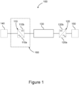
- Figure 1 illustrates generically, an example of a power transmission network 100.
- the illustration is not intended to be limited to representing a particular power transmission scheme, such as a monopole or bipole HVDC transmission network, but is moreover provided as a generic example illustrating principles of operation of a power transmission network that are useful for understanding the invention.
- the power transmission network 100 may represent, generically, a monopole or bipole scheme, or may represent a multiterminal power transmission scheme, for instance.
- specific features in the illustration are shown connected to each other with a specific number of connections, it will be understood that this is not intended to be limiting either, but moreover to illustrate a generic connection between features/components.
- the power transmission network 100 includes a first power converter 110 (also known as a converter station, power electronics-based resource, inverter, inverter station, etc.), a second power converter 120, a transmission medium 130, a first AC network 140, a second AC network 150, and a converter station 160.
- a first power converter 110 also known as a converter station, power electronics-based resource, inverter, inverter station, etc.
- a second power converter 120 also known as a converter station, power electronics-based resource, inverter, inverter station, etc.
- a second power converter 120 also known as a converter station, power electronics-based resource, inverter, inverter station, etc.
- the power converters 110, 120 can convert AC power to DC power, acting essentially as rectifiers; or DC power to AC power, acting essentially as inverters.
- the power converters 110, 120 may each comprise a single converter in the case of a monopole system, or two converters in the case of a bipole system.
- the power converters 110, 120 may represent a plurality of converter stations arranged as a multi-terminal power transmission system.
- the first power converter 110 comprises a first AC side 110a and a first DC side 110b.
- the second power converter 120 comprises a second AC side 120a and a second DC side 120b.
- the first power converter 110 is connected to a first AC network 140.
- the first AC network 140 is connected to the first AC side 110a of the first power converter 110.
- the second power converter 120 is connected to a second AC network 150.
- the second AC network 150 is connected to the second AC side 120a of the second power converter 120.
- the first AC network 140 and/or second AC network 150 may be electrical power transmission systems comprising power generation apparatus, transmission apparatus, distribution apparatus, and electrical loads.
- the first AC network 140 and/or second AC network 150 may comprise a renewable power generation network such as a wind-power generation network, solar-power generation network, bio-power generation network.
- the first AC network 140 or second AC network 150 may be a consumer network.
- the first AC network 140 may be a power generation network, with second AC network 150 being a consumer network, for instance.
- the power converters 110, 120 may be geographically remote.
- the first power converter 110 may reside on an off-shore platform with a wind farm, and the second power converter 120 may reside on-shore.
- the power transmission medium 130 connects the first power converter 110 and the second power converter 120.
- the power transmission medium 130 is connected between the first DC side 110b of the first power converter 110 and the second DC side 120b of the second power converter 120.
- the power transmission medium 130 may comprise electrical cables (or overhead lines) and other electrical components for connecting the first and second power converters 110, 120.
- the power transmission medium 130 may comprise a conductor providing a first electrical pole; and/or a conductor providing a second electrical pole.
- a neutral arrangement may also be provided interconnecting the first and second power converters 110, 120.
- the power transmission medium 130 provides the medium through which DC power is transferred between the power converters 110, 120.
- the operation of the power transmission system 100 can be generically described as follows.
- the first AC network 140 generates AC power that is provided to the first power converter 110 at the first AC side 11 0a.
- the first power converter 110 converts the received AC power to DC power for transmission to the transmission medium 130.
- the DC power is transmitted from the first DC side 110b of the first power converter 110 to the transmission medium 130.
- the second DC side 120b of the second power converter 120 receives DC power from the transmission medium 130.
- the second power converter 120 converts the received DC power to AC power.
- the AC power is then provided from the second AC side 120a of the second power converter 120 to the second AC network 150 for consumption, for instance.
- the first power converter 110 can also receive power from the transmission medium 130.
- the first power converter 110 can thus be configured to transfer real or reactive power in either direction, into or out of the first AC network 140.
- the second power converter 120 can also be configured to transfer real or reactive power in either direction, into or out of the second AC network 150.
- various other electrical components may be located at any particular location or with any particular feature/component in the example 100. These may include power converter valves, switches, transformers, resistors, reactors, surge arrestors, harmonic filters and other components well known in the art.
- converters or power conversion means may comprise a number of different technologies such as voltage sourced converters (for instance using insulated gate bipolar transistor (IGBT) valves). Such converters may generally be considered to use 'power electronics.
- Power electronic converters may comprise multi-level voltage sourced converters, for instance.
- the power transmission network 100 may be used with three-phase power systems.
- three conductors supply respective first, second and third phases of AC power to a consumer.
- Each of the first, second and third phases will typically have equal magnitude voltages or currents, which are displaced in phase from each other by 120°.
- the power transmission network 100 may further comprise a controller for controlling the operation of components of the power transmission network 100.
- a controller may be provided for executing the methods described herein.
- Such a controller may control the power converter 110, 120, for instance.
- Such a controller may be referred to as a controller means or control means.
- the controller may be the controller 200 of Figure 2 .
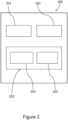
- FIG. 2 illustrates an embodiment of a controller 200 as may be used in implementing the invention described herein.
- the controller 200 comprises a memory 201 and at least one processor 202.
- the memory 201 comprises computer-readable instructions, which when executed by the at least one processor 202, cause the controller 200 to perform the method/s described herein.
- the controller 200 is shown as comprising a transceiver arrangement 203 which may comprise a separate transmitter 204 and receiver 205.
- the transceiver arrangement 203 may be used to operatively communicate with other components or features of embodiments described herein either directly or via a further interface such as a network interface.
- the transceiver arrangement 203 may for instance send and receive control signals using transmitter 204 and receiver 205.
- the control signals may contain or define electrical control parameters such as reference currents or reference voltages.
- the at least one processor 202 is capable of executing computer-readable instructions and/or performing logical operations.
- the at least one processor 202 may be a microcontroller, microprocessor, central processing unit (CPU), field programmable gate array (FPGA) or similar programmable controller.
- the controller may further comprise a user input device and/or output device.
- the processor 202 is communicatively coupled to the memory 201 and may in certain embodiments be coupled to the transceiver 203.
- the memory 201 may be a computer readable storage medium.
- the memory 201 may include a non-volatile computer storage medium.
- the memory 201 may include a hard disk drive, flash memory etc.
- the controller 200 may additionally include a user input device interface and/or a user output device interface, which may allow for visual, audible or haptic inputs/outputs. Examples include interfaces to electronic displays, touchscreens, keyboards, mice, speakers and microphones.
- FIG. 3 illustrates the converter station 160 in more detail.
- the converter station 160 comprises a first branch 210, a second branch 220, and the first power converter 110.
- the first branch 210 comprises a first switch 212 in series with a first transformer 214 in series with a second switch 216.
- the second branch 220 comprises a third switch 222 in series with a second transformer 224 in series with a fourth switch 226.
- the first branch 210 and the second branch 220 are connected in parallel to the AC side 110a of the first power converter 110.
- the first and third switches 212, 222 are connected to the AC network 140.
- the second and fourth switches 216, 226 are connected to the AC side 110a of the first power converter 110.
- the DC side 110b of the first power converter 110 is connected to the power transmission medium 130.
- the first and third switches 212, 222 may have current breaking capability, whereas the second and fourth switches 216, 226 may not have current breaking capability. Alternatively, the first and third switches 212, 222 may have higher current breaking capabilities compared to the second and fourth switches 216, 226.
- the first and third switches 212, 222 may be circuit breakers and the second and fourth switches 216, 226 may be circuit breakers having low current breaking capabilities or off-load switches such as isolators or disconnectors.
- the converter station 160 comprises the first power converter 110, it is to be understood that embodiments should not be limited in this way.
- a converter station may comprise the second power converter 120 instead of the first power converter 110.
- the first transformer 214 and the second transformer 224 are conventional AC transformers.
- the first transformer 214 and the second transformer 224 have a primary side and a secondary side, and a turns ratio between the primary and secondary side.
- the turns ratio determines a ratio of voltage increase or decrease from the primary side to the second side, and/or vice versa.
- a purpose of the first and second transformers is to step the voltage of the AC power from the AC network 140 to a suitable range to be received by the first power converter 110.
- the first transformer 214 and the second transformer 224 may be variable transformers capable of having a variable turns ratio.
- the first and second transformers 214, 224 may be configured in any manner as required by a specific application.
- the first transformer 214 and the second transformer 224 also provide electrical isolation from the AC network 140 to the power converter 110.
- Figure 3 shows a normal operation, discussed in more detail later below, wherein the first switch 212 and the second switch 216 are in a closed position, i.e., provide a short circuit, such that power can be transferred through the first switch 212 and the second switch 216.
- the third switch 222 and the fourth switch 226 are also in a closed position, i.e., provide a short circuit, such that power can be transferred through the third switch 222 and the fourth switch 226.
- Figure 4 shows an embodiment of a method 400 for controlling a converter station 160 and/or a power transmission network 100.
- the first AC network 140 generates AC power.
- the AC power is transferred to the first AC side 110a of the first power converter 110 via the first branch 210 and the second branch 220.
- the first branch 210 and the second branch 220 are, from an operational perspective, identical, and therefore each branch may transfer a similar amount of power.
- the first and second branches 210, 220 may be different, and as such the converter station 160 may be configured to transfer a different amount of power through the first branch 210 compared to the second branch 220.
- the specificity of the first and second branches 210, 220 may be application dependant.
- AC power is transferred from the AC network 140 to the first power converter 110, via the first and second branches 210, 220, with the first, second, third and fourth switches 212, 222, 216, 226 in the closed positions, and the transformers 214, 224 providing a suitable step-up or step-down of the AC voltage.
- the first power converter 110 converts the AC power to DC power that is transferred to the power transmission medium 130.
- the first power converter 110 may also convert DC power from the power transmission medium 130 to AC power for the AC network 140. As such, the power converter 110 is initially controlled to transfer power between the AC network 140 and the transmission network 100 via the first branch 210 and the second branch 220.
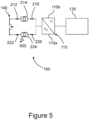
- a fault 500 then occurs in the second branch 220, resulting in a fault condition.
- the fault 500 may be caused by, for example, a break in an insulation in the second transformer 224.
- a fault may be understood to be anything that causes an abnormal current to flow through the converter station 160 or the second branch 220, or causes an abnormal voltage in the converter station 160 or the second branch 220.
- An abnormal current or voltage may be any current or voltage that is not expected during a normal operation of the converter station 160.
- a current path is now present in the second branch 220 that allows a current to flow from the power transmission network 100 to, for example, a ground or Earth.
- the fault 500 may cause a first fault current to travel from the first AC network 140 to the fault 500 via the first branch 210.
- the fault 500 may cause a second fault current to travel from the first AC network 140 to the fault 500 via the second branch 220.
- a third fault current may travel from the transmission medium 130, via the first power converter 110, to the fault 500.
- a conventional method to manage the fault 500 tends to isolate the fault 500 by opening switches on both sides of the transmission medium 130.
- the power transmission network 100 may then be restarted in a new configuration that accounts for the fault 500.
- the conventional approach tends to require considerable time to detect the fault 500, and to isolate and restart the power transmission network 100, during which time the transmission medium 130 and the second power converter 120 are out of service. This can be problematic for maintaining voltage stability on the second AC network 150, considering reactive power requirements of the second AC network 150.
- a benefit of controlling the converter station 160 according to the methods disclosed herein is that the second power converter 120 tends to continue transferring reactive power to the second AC network 150, even during the fault condition.
- a further benefit is that the converter station 160 tends to be ready to resume transferring power from the first AC network 140 to the transmission medium 130 shortly after the fault has been detected and cleared or isolated by the switches. This is because the converter station 160 is reconfigured faster compared to conventional methods, because there is no need to shut down the transmission network 100 or to re-energise the transmission network 100 in a new configuration after the fault has been cleared or isolated. As such, the overall downtime of the power transmission network 100, as a result of the fault 500, tends to be less when compared with a conventional approach.
- the controller 200 detects the fault 500 in the second branch 220.
- the controller 200 can detect the fault by, for example, measuring voltages and currents through a transducer installed in the first branch 210 and/or second branch 220 of the converter station 160, or by any other voltage or current sensing or measuring means.
- the fault 500 may be anywhere between the third switch 222 and the fourth switch 226.
- the controller 200 issues a first command to reduce an AC side 110a voltage of the power converter 110. This causes a reduction in the third fault current.
- the first command may be issued to the power converter 110 or another controller.
- the first command may include instructions to reduce the AC side 110a voltage to a first reference value.
- the first reference value may be zero, such that the first command to reduce the AC side 110a voltage of the power converter 110 causes the third fault current transferred from the AC side 110a of the converter 110 to converge to zero.
- the first reference value may be a finite non-zero value, such that the first command to reduce the AC side 110a voltage of the power converter 110 causes the third fault current from the AC side 110a of the converter 110 to converge to a value below, for example, a current opening capability of the fourth switch 226.
- the first command causes the power converter 110 to clamp the AC side 110a voltage to zero or to below the threshold value.
- the controller 200 issues a second command to open the first switch 212, the third switch 222, and the fourth switch 226.
- the second command causes the first switch 212, the third switch 222, and the fourth switch 226 to break their respective connections, such that they are in open circuit configuration which prevents current from conducting through the first switch 212, the third switch 222, and the fourth switch 226.
- the second command may be issued to the first switch 212, the third switch 222, and the fourth switch 226 directly, or to another controller.
- any path or route by which current may be transferred out of the power transmission network 100 as a result of the fault 500 has been removed, disconnected, or broken, and as such the second transformer 224 (including the fault 500) is isolated from the power transmission network 100, as shown in Figure 6 .
- the method 400 may further comprise, at step s450, the controller 200 issuing a DC voltage command to change or adjust the DC side 110b voltage of the power converter 110 to a DC reference value.
- the DC voltage command may be issued to the first power converter 110, and/or to the second power converter 120, and/or to another controller.
- the DC reference value may be a nominal operating DC voltage of the transmission medium 130. This may be, for example, 320kV or 525kV.
- a purpose of the DC voltage command is to normalise the DC voltage on the transmission medium 130 after the fault 500 has been isolated.
- the power transmission network 100 may be restored to a normal operation, wherein real and reactive power may flow between first and/or second power converters 110 and 120.
- the controller 200 then issues a third command to close the first switch 212 (i.e., return the first switch 212 to a conducting state), and also issues a fourth command to restore an AC side 110a voltage of the power converter 110 to an AC reference value.
- the AC reference value may be a value of, or a value close to, the AC side 110a voltage before the fault condition, for example the value of the AC side 110a voltage in step s410.
- the first branch 210 is able to transfer power between the first AC grid 140 to the first power converter 110, as shown in Figure 7 .
- the third command may be issued to the first switch 212 or to another controller.
- the fourth command may be issued to the first power converter 110 or to another controller.
- the controller 200 may issue a fifth command to transfer or connect wind-turbine feeders to the first AC network 140.
- the fifth command may be issued to the power transmission network 100, to a wind farm controller, or to another controller.
- the controller 200 has reconfigured the power converter 110 to transfer power between the AC network 140 and the power transmission medium 130 via the first branch 210 and not the second branch 220, such that the converter station 160 can transfer power from the first AC network 140 to the transmission medium 130 without the second branch 220.
- the methods disclosed herein tend to allow the converter station 160 to transfer power between the first AC network 140 to the transmission medium 130, shortly after the fault 500 has been detected and cleared, which reduces the downtime of the power transmission network 100.
- the fault 500 tends to be isolated faster, compared to conventional methods, because the fault 500 can be managed by controlling the converter station 160 only on one side of the transmission medium 130.
- the methods disclosed herein tend not to need to re-energise the transmission network 100 and/or first AC network 140 after the fault 500 has been isolated, which further helps reduce any downtime of the power transmission network 100.
- the methods disclosed herein tend to be particularly advantageous when operating a transmission scheme or power transmission network 100 wherein the first power converter 110 is located offshore, and the second power converter 120 is located onshore.
- the first power converter 110 may be, for example, located on a fixed or floating platform.
- the converter station 160 can benefit from only using switches that do not require current breaking capability, which tend to be more space efficient and thus more cost effective, which is a high priority on a fixed or floating platform.
- the disclosure is related to a method for controlling a power transmission scheme comprising a sending-end converter connected to at least two AC networks via two parallel transformers, each transformer connected to the AC network through a grid-side switch and to the converter through a converter-side switch, the method comprising: isolating the converter from the AC networks, upon detecting a fault in one of the transformer branches, by issuing a sixth command to open the two grid-side switches; clamping an AC voltage of the sending-end converter to zero; issuing a seventh command to open the converter-side switch associated with the faulty transformer branch for isolating the faulty transformer branch from the scheme; building up the AC voltage of the sending-end converter from zero to a nominal value; and issuing a eighth command to close the grid-side AC breaker associated with the healthy transformer to facilitate operation of the power transmission scheme with the healthy transformer in line.
- the building up the AC voltage involves bringing the converter AC voltage directly to the nominal value or ramping up the AC voltage from zero to the nominal value at a pre-defined rate.
Landscapes
- Engineering & Computer Science (AREA)
- Power Engineering (AREA)
- Inverter Devices (AREA)
Abstract
There is provided a method (400) for controlling a converter station (160) in a power transmission network (100), the converter station (160) comprising a first branch (210), a second branch (220), and a power converter (110); wherein the first branch (210) comprises: a first switch (212) in series with a first transformer (214) in series with a second switch (216); wherein the second branch (220) comprises: a third switch (222) in series with a second transformer (224) in series with a fourth switch (226); wherein the first branch (210) and the second branch (220) are in parallel, the first and third switches (212, 222) are connected to an AC network (140), and the second and fourth switches (216, 226) are connected to an AC side (110a) of the power converter (110). The method comprises: initially controlling, by a controller (200), the power converter (110) to transfer power between the AC network (140) and the transmission network (100) via the first branch (210) and the second branch (220); detecting, by the controller (200), a fault (500) in the second branch (220); in response to detecting the fault (500) in the second branch (220): issuing, by the controller (200), a first command to reduce an AC side (110a) voltage of the power converter (110); issuing, by the controller (200), a second command to open the first switch (212), the third switch (222), and the fourth switch (226); in response to the fourth switch (226) opening: issuing, by the controller (200), a third command to close the first switch (212); and issuing, by the controller (200), a fourth command to restore an AC side (110a) voltage of the power converter (110) to an AC reference value.
Description
- The present invention relates to a method and a controller for controlling a power transmission network, and more particularly for controlling a converter station in a power transmission network.
- In high voltage direct current (HVDC) power transmission networks, alternating current (AC) power is typically converted to direct current (DC) power for transmission via overhead lines, under-sea cables and/or underground cables, also known as a transmission medium. This conversion removes a need to compensate for the AC reactive/capacitive load effects imposed by the power transmission medium, i.e., the transmission line or cable, and reduces the cost per kilometre of the lines and/or cables. The conversion tends to be beneficial, for example when power is transmitted over a long distance. DC power can also be transmitted directly from offshore wind parks to onshore AC power transmission networks, for instance.
- The conversion between DC power and AC power is utilised where it is necessary to interconnect DC and AC power, for example between an AC grid and a HVDC transmission line. In power transmission networks, power conversion means, also known as power converters (i.e., power converters in converter stations, power electronics-based resources, power inverters etc.) are required at each interface or interconnection between AC and DC power to implement the required conversion from AC to DC or from DC to AC.
- A HVDC transmission network will thus typically include a transmission medium with a power converter connected on either side of the transmission medium. The power converters are typically connected to AC networks via switchgears. The power converter and its respective switchgear may be referred to as a converter station. A typical HVDC transmission network will thus have two converter stations, one on either side of the transmission medium, interfacing the transmission medium to a respective AC network.
- A fault may occur in one of the converter stations. A conventional method to manage the fault comprises isolating the fault by opening circuit breakers and/or disconnectors on both sides of the transmission medium. The transmission network or power system may then be restarted in a new configuration that accounts for the fault. The conventional approach tends to require considerable time to detect and isolate the fault, and restart the transmission network, during which time the transmission medium and the converter stations are out of service. This can be problematic for maintaining power stability in the transmission network or power system. The increased downtime also tends to reduce the cost-effectiveness of operating the transmission network.
- In light of these considerations and emerging grid requirements, it is desired to develop methods that provide improved fault management of a fault in a transmission network.
- According to a first aspect, there is provided a method for controlling a converter station in a power transmission network, the converter station comprising a first branch, a second branch, and a power converter. The first branch comprises a first switch in series with a first transformer in series with a second switch. The second branch comprises a third switch in series with a second transformer in series with a fourth switch. The first branch and the second branch are in parallel, the first and third switches are connected to an AC network, and the second and fourth switches are connected to an AC side of the power converter. The method comprises initially controlling, by a controller, the power converter to transfer power between the AC network and the transmission network via the first branch and the second branch. Detecting, by the controller, a fault in the second branch. In response to detecting the fault in the second branch: issuing, by the controller, a first command to reduce an AC side voltage of the power converter; and issuing, by the controller, a second command to open the first switch, the third switch, and the fourth switch. In response to the fourth switch opening: issuing, by the controller, a third command to close the first switch; and issuing, by the controller, a fourth command to restore an AC side voltage of the power converter to an AC reference value.
- In other words, issuing the third and fourth commands causes the power converter to transfer power between the AC network and the transmission network via the first branch (only) and not via the second branch.
- In some embodiments, the power converter further comprises a DC side that is connected to a power transmission medium. The method may further comprise issuing, by the controller, a DC voltage command to change or adjust a DC side voltage of the power converter to a DC reference value. This may be performed after the converter output voltage is clamped, i.e. before the switches are opened.
- In some embodiments, detecting the fault in the second branch comprises detecting a fault between the third switch and the fourth switch.
- In some embodiments, the fault comprises any one of: a break in an insulation in the second transformer, and/or an insulation failure in a component in the second branch; and/or an abnormal current flow through the converter station; and/or an abnormal current flow through the second branch; and/or an abnormal voltage in the converter station; and/or an abnormal voltage in the second branch; and/or a current path in the second branch that allows a current to flow from the power transmission network to a ground or Earth.
- In some embodiments, the first command includes instructions to reduce an AC side voltage of the power converter to a first reference value; wherein the first reference value is zero, such that issuing the first command to reduce the AC side voltage of the power converter causes the AC side voltage of the power converter to converge to zero.
- In some embodiments, the first command includes instructions to reduce an AC side voltage of the power converter to a first reference value; wherein the first reference value is a current opening capability of the fourth switch.
- In some embodiments, the converter station is an asymmetrical monopole, or a bipole, or a symmetrical monopole HVDC transmission scheme, and initially controlling the power converter comprises initially controlling, by the controller, the power converter for the asymmetrical monopole, or the bipole, or the symmetrical monopole HVDC transmission scheme.
- In some embodiments, the method is for controlling a power transmission network; the method further comprising, in response to the first switch closing: issuing, by the controller, a fifth command to the power transmission network, and/or to a windfarm controller, to transfer or connect wind-turbine feeders to the first AC network.
- According to a second aspect, there is provided a controller for controlling a converter station in a power transmission network, the converter station comprising a first branch, a second branch, and a power converter; wherein the first branch comprises: a first switch in series with a first transformer in series with a second switch; wherein the second branch comprises: a third switch in series with a second transformer in series with a fourth switch; wherein the first branch and the second branch are in parallel, the first and third switches are connected to an AC network, and the second and fourth switches are connected to an AC side of the power converter. The controller is configured to initially control the power converter to transfer power between the AC network and the transmission network via the first branch and the second branch; detect a fault in the second branch; and in response to detecting the fault in the second branch: issue a first command to reduce an AC side voltage of the power converter; and issue a second command to open the first switch, the third switch, and the fourth switch. In response to the fourth switch opening, the controller is configured to: issue a third command to close the first switch; and issue a fourth command to restore an AC side voltage of the power converter to an AC reference value.
- Generally, the controller tends to be configured to execute the methods described herein.
- According to a third aspect, there is provided a converter station for a power transmission network, the converter station comprising: a first branch comprising: a first switch in series with a first transformer in series with a second switch; a second branch comprising: a third switch in series with a second transformer in series with a fourth switch; a power converter comprising an AC side and a DC side; and the controller of the second aspect configured to control the converter station. The first branch and the second branch are in parallel; the first and third switches are connected to an AC network; and the second and fourth switches are connected to the AC side of the power converter.
- In some embodiments, the power converter is a Voltage Source Converter for providing power to a power transmission medium.
- In some embodiments, the converter station is located onshore.
- In some embodiments, the converter station is located offshore on a fixed platform.
- In some embodiments, the converter station is located offshore on a floating platform.
- In some embodiments, the first and third switches have higher current breaking capability compared to the second and fourth switches (216, 226).
- In some embodiments, the first and third switches are circuit breakers. In some embodiments, the second and fourth switches are isolators or disconnectors.
- According to a fourth aspect, there is provided an asymmetrical monopole or a symmetrical monopole HVDC transmission scheme comprising the converter station of the third aspect.
- According to a fifth aspect, there is provided a power transmission network comprising an AC network; a HVDC power transmission medium; and the converter station of the third aspect. The converter station is connected between the AC network and the HVDC power transmission medium.
- According to a sixth aspect, there is provided a computer program comprising instructions which when executed by a processor of a controller for controlling a power converter, cause the controller to perform the method of the first aspect.
- According to a seventh aspect, there is provided a non-transitory computer-readable storage medium comprising the computer program of the sixth aspect.
- It will be appreciated that particular features of different aspects of the invention share the technical effects and benefits of corresponding features of other aspects of the invention. More specifically, the controller, the converter station, the asymmetrical or symmetrical monopole HVDC transmission scheme, the power transmission network, the computer program, and the non-transitory computer-readable medium, share the technical effects and benefits of the method of the invention.
- It will also be appreciated that the use of the terms "first" and "second", and the like, are merely intended to help distinguish between similar features and are not intended to indicate a relative importance of one feature over another, unless otherwise specified.
- Within the scope of this application, it is expressly intended that the various aspects, embodiments, examples, and alternatives set out in the preceding paragraphs, and the claims and/or the following description and drawings, and in particular the individual features thereof, may be taken independently or in any combination. That is, all embodiments and all features of any embodiment can be combined in any way and/or combination, unless such features are incompatible.
-
-
Figure 1 is a schematic illustration of an example of a power transmission network including a converter station; -
Figure 2 shows an embodiment of a controller for controlling a converter station; -
Figure 3 is a schematic illustration of an example of a converter station in a first configuration; -
Figure 4 shows an embodiment of a method for controlling a converter station and/or a power transmission network; -
Figure 5 is a schematic illustration of an example of a converter station in a fault condition; -
Figure 6 is a schematic illustration of an example of a converter station in a second configuration; and -
Figure 7 is a schematic illustration of an example of a converter station in a third configuration. -
Figure 1 illustrates generically, an example of apower transmission network 100. The illustration is not intended to be limited to representing a particular power transmission scheme, such as a monopole or bipole HVDC transmission network, but is moreover provided as a generic example illustrating principles of operation of a power transmission network that are useful for understanding the invention. In this manner, thepower transmission network 100 may represent, generically, a monopole or bipole scheme, or may represent a multiterminal power transmission scheme, for instance. Hence whilst specific features in the illustration are shown connected to each other with a specific number of connections, it will be understood that this is not intended to be limiting either, but moreover to illustrate a generic connection between features/components. Related, is that relative dimensions or distances between components perceived in the illustration are also not intended to be limiting. It will therefore be understood that principles and features in thenetwork 100 and herein discussed can be applied to networks comprising thecontroller 200 ofFigure 2 , for instance; or networks controlled according to amethod 400 ofFigure 4 . - The
power transmission network 100 includes a first power converter 110 (also known as a converter station, power electronics-based resource, inverter, inverter station, etc.), asecond power converter 120, atransmission medium 130, afirst AC network 140, asecond AC network 150, and aconverter station 160. - The
power converters power converters power converters first power converter 110 comprises afirst AC side 110a and afirst DC side 110b. Generically, thesecond power converter 120 comprises asecond AC side 120a and asecond DC side 120b. - The
first power converter 110 is connected to afirst AC network 140. Thefirst AC network 140 is connected to thefirst AC side 110a of thefirst power converter 110. Thesecond power converter 120 is connected to asecond AC network 150. Thesecond AC network 150 is connected to thesecond AC side 120a of thesecond power converter 120. - The
first AC network 140 and/orsecond AC network 150 may be electrical power transmission systems comprising power generation apparatus, transmission apparatus, distribution apparatus, and electrical loads. Thefirst AC network 140 and/orsecond AC network 150 may comprise a renewable power generation network such as a wind-power generation network, solar-power generation network, bio-power generation network. Thefirst AC network 140 orsecond AC network 150 may be a consumer network. By way of non-limiting example, thefirst AC network 140 may be a power generation network, withsecond AC network 150 being a consumer network, for instance. In particular examples, thepower converters first power converter 110 may reside on an off-shore platform with a wind farm, and thesecond power converter 120 may reside on-shore. - The
power transmission medium 130 connects thefirst power converter 110 and thesecond power converter 120. Thepower transmission medium 130 is connected between thefirst DC side 110b of thefirst power converter 110 and thesecond DC side 120b of thesecond power converter 120. Thepower transmission medium 130 may comprise electrical cables (or overhead lines) and other electrical components for connecting the first andsecond power converters power transmission medium 130 may comprise a conductor providing a first electrical pole; and/or a conductor providing a second electrical pole. For bipole schemes, a neutral arrangement may also be provided interconnecting the first andsecond power converters power transmission medium 130 provides the medium through which DC power is transferred between thepower converters - The operation of the
power transmission system 100 can be generically described as follows. Thefirst AC network 140 generates AC power that is provided to thefirst power converter 110 at the first AC side 11 0a. Thefirst power converter 110 converts the received AC power to DC power for transmission to thetransmission medium 130. The DC power is transmitted from thefirst DC side 110b of thefirst power converter 110 to thetransmission medium 130. Thesecond DC side 120b of thesecond power converter 120 receives DC power from thetransmission medium 130. Thesecond power converter 120 converts the received DC power to AC power. The AC power is then provided from thesecond AC side 120a of thesecond power converter 120 to thesecond AC network 150 for consumption, for instance. - Additionally, in some circumstances, the
first power converter 110 can also receive power from thetransmission medium 130. Thefirst power converter 110 can thus be configured to transfer real or reactive power in either direction, into or out of thefirst AC network 140. Thesecond power converter 120 can also be configured to transfer real or reactive power in either direction, into or out of thesecond AC network 150. - It will be appreciated that various other electrical components may be located at any particular location or with any particular feature/component in the example 100. These may include power converter valves, switches, transformers, resistors, reactors, surge arrestors, harmonic filters and other components well known in the art.
- It will be appreciated that converters or power conversion means may comprise a number of different technologies such as voltage sourced converters (for instance using insulated gate bipolar transistor (IGBT) valves). Such converters may generally be considered to use 'power electronics. Power electronic converters may comprise multi-level voltage sourced converters, for instance.
- Moreover, it will be understood that the
power transmission network 100 may be used with three-phase power systems. In a three-phase power system, three conductors supply respective first, second and third phases of AC power to a consumer. Each of the first, second and third phases will typically have equal magnitude voltages or currents, which are displaced in phase from each other by 120°. - The
power transmission network 100 may further comprise a controller for controlling the operation of components of thepower transmission network 100. For instance, a controller may be provided for executing the methods described herein. Such a controller may control thepower converter controller 200 ofFigure 2 . -
Figure 2 illustrates an embodiment of acontroller 200 as may be used in implementing the invention described herein. - The
controller 200 comprises amemory 201 and at least oneprocessor 202. Thememory 201 comprises computer-readable instructions, which when executed by the at least oneprocessor 202, cause thecontroller 200 to perform the method/s described herein. - The
controller 200 is shown as comprising atransceiver arrangement 203 which may comprise aseparate transmitter 204 andreceiver 205. Thetransceiver arrangement 203 may be used to operatively communicate with other components or features of embodiments described herein either directly or via a further interface such as a network interface. Thetransceiver arrangement 203 may for instance send and receive controlsignals using transmitter 204 andreceiver 205. The control signals may contain or define electrical control parameters such as reference currents or reference voltages. - The at least one
processor 202 is capable of executing computer-readable instructions and/or performing logical operations. The at least oneprocessor 202 may be a microcontroller, microprocessor, central processing unit (CPU), field programmable gate array (FPGA) or similar programmable controller. The controller may further comprise a user input device and/or output device. Theprocessor 202 is communicatively coupled to thememory 201 and may in certain embodiments be coupled to thetransceiver 203. - The
memory 201 may be a computer readable storage medium. For instance, thememory 201 may include a non-volatile computer storage medium. For example, thememory 201 may include a hard disk drive, flash memory etc. - Whilst not shown, the
controller 200 may additionally include a user input device interface and/or a user output device interface, which may allow for visual, audible or haptic inputs/outputs. Examples include interfaces to electronic displays, touchscreens, keyboards, mice, speakers and microphones. -
Figure 3 illustrates theconverter station 160 in more detail. Theconverter station 160 comprises afirst branch 210, asecond branch 220, and thefirst power converter 110. - The
first branch 210 comprises afirst switch 212 in series with afirst transformer 214 in series with asecond switch 216. Thesecond branch 220 comprises athird switch 222 in series with asecond transformer 224 in series with afourth switch 226. Thefirst branch 210 and thesecond branch 220 are connected in parallel to theAC side 110a of thefirst power converter 110. The first andthird switches AC network 140. The second andfourth switches AC side 110a of thefirst power converter 110. TheDC side 110b of thefirst power converter 110 is connected to thepower transmission medium 130. - The first and
third switches fourth switches third switches fourth switches third switches fourth switches - Although in this embodiment, the
converter station 160 comprises thefirst power converter 110, it is to be understood that embodiments should not be limited in this way. For example, in other embodiments, a converter station may comprise thesecond power converter 120 instead of thefirst power converter 110. - The
first transformer 214 and thesecond transformer 224 are conventional AC transformers. Thefirst transformer 214 and thesecond transformer 224 have a primary side and a secondary side, and a turns ratio between the primary and secondary side. The turns ratio determines a ratio of voltage increase or decrease from the primary side to the second side, and/or vice versa. - A purpose of the first and second transformers is to step the voltage of the AC power from the
AC network 140 to a suitable range to be received by thefirst power converter 110. - The
first transformer 214 and thesecond transformer 224 may be variable transformers capable of having a variable turns ratio. The first andsecond transformers - The
first transformer 214 and thesecond transformer 224 also provide electrical isolation from theAC network 140 to thepower converter 110. -
Figure 3 shows a normal operation, discussed in more detail later below, wherein thefirst switch 212 and thesecond switch 216 are in a closed position, i.e., provide a short circuit, such that power can be transferred through thefirst switch 212 and thesecond switch 216. Thethird switch 222 and thefourth switch 226 are also in a closed position, i.e., provide a short circuit, such that power can be transferred through thethird switch 222 and thefourth switch 226. -
Figure 4 shows an embodiment of amethod 400 for controlling aconverter station 160 and/or apower transmission network 100. At step s410, during a normal operation thefirst AC network 140 generates AC power. The AC power is transferred to thefirst AC side 110a of thefirst power converter 110 via thefirst branch 210 and thesecond branch 220. Thefirst branch 210 and thesecond branch 220 are, from an operational perspective, identical, and therefore each branch may transfer a similar amount of power. However, in some examples, the first andsecond branches converter station 160 may be configured to transfer a different amount of power through thefirst branch 210 compared to thesecond branch 220. The specificity of the first andsecond branches - During the normal operation, AC power is transferred from the
AC network 140 to thefirst power converter 110, via the first andsecond branches fourth switches transformers first power converter 110 converts the AC power to DC power that is transferred to thepower transmission medium 130. - The
first power converter 110 may also convert DC power from thepower transmission medium 130 to AC power for theAC network 140. As such, thepower converter 110 is initially controlled to transfer power between theAC network 140 and thetransmission network 100 via thefirst branch 210 and thesecond branch 220. - With reference to
Figure 5 , in this example, afault 500 then occurs in thesecond branch 220, resulting in a fault condition. Thefault 500 may be caused by, for example, a break in an insulation in thesecond transformer 224. - Generally, a fault may be understood to be anything that causes an abnormal current to flow through the
converter station 160 or thesecond branch 220, or causes an abnormal voltage in theconverter station 160 or thesecond branch 220. An abnormal current or voltage may be any current or voltage that is not expected during a normal operation of theconverter station 160. - As a result of the
fault 500, a current path is now present in thesecond branch 220 that allows a current to flow from thepower transmission network 100 to, for example, a ground or Earth. - The
fault 500 may cause a first fault current to travel from thefirst AC network 140 to thefault 500 via thefirst branch 210. Thefault 500 may cause a second fault current to travel from thefirst AC network 140 to thefault 500 via thesecond branch 220. Additionally, a third fault current may travel from thetransmission medium 130, via thefirst power converter 110, to thefault 500. There are thus three routes by which a fault current may be transferred out of thepower transmission network 100 as a result of thefault 500. - A conventional method to manage the
fault 500 tends to isolate thefault 500 by opening switches on both sides of thetransmission medium 130. Thepower transmission network 100 may then be restarted in a new configuration that accounts for thefault 500. The conventional approach tends to require considerable time to detect thefault 500, and to isolate and restart thepower transmission network 100, during which time thetransmission medium 130 and thesecond power converter 120 are out of service. This can be problematic for maintaining voltage stability on thesecond AC network 150, considering reactive power requirements of thesecond AC network 150. - A benefit of controlling the
converter station 160 according to the methods disclosed herein is that thesecond power converter 120 tends to continue transferring reactive power to thesecond AC network 150, even during the fault condition. - A further benefit is that the
converter station 160 tends to be ready to resume transferring power from thefirst AC network 140 to thetransmission medium 130 shortly after the fault has been detected and cleared or isolated by the switches. This is because theconverter station 160 is reconfigured faster compared to conventional methods, because there is no need to shut down thetransmission network 100 or to re-energise thetransmission network 100 in a new configuration after the fault has been cleared or isolated. As such, the overall downtime of thepower transmission network 100, as a result of thefault 500, tends to be less when compared with a conventional approach. These and other benefits tend to be realised when controlling theconverter station 160 according to the methods disclosed herein, as will now be discussed. - With reference to
Figure 4 , once thefault 500 has occurred, at a step s420, thecontroller 200 detects thefault 500 in thesecond branch 220. Thecontroller 200 can detect the fault by, for example, measuring voltages and currents through a transducer installed in thefirst branch 210 and/orsecond branch 220 of theconverter station 160, or by any other voltage or current sensing or measuring means. Thefault 500 may be anywhere between thethird switch 222 and thefourth switch 226. - At step s430, in response to detecting the
fault 500 in thesecond branch 220, thecontroller 200 issues a first command to reduce anAC side 110a voltage of thepower converter 110. This causes a reduction in the third fault current. The first command may be issued to thepower converter 110 or another controller. - The first command may include instructions to reduce the
AC side 110a voltage to a first reference value. The first reference value may be zero, such that the first command to reduce theAC side 110a voltage of thepower converter 110 causes the third fault current transferred from theAC side 110a of theconverter 110 to converge to zero. Alternatively, the first reference value may be a finite non-zero value, such that the first command to reduce theAC side 110a voltage of thepower converter 110 causes the third fault current from theAC side 110a of theconverter 110 to converge to a value below, for example, a current opening capability of thefourth switch 226. - In other words, the first command causes the
power converter 110 to clamp theAC side 110a voltage to zero or to below the threshold value. - At step s440, also in response to detecting the
fault 500 in thesecond branch 220, thecontroller 200 issues a second command to open thefirst switch 212, thethird switch 222, and thefourth switch 226. The second command causes thefirst switch 212, thethird switch 222, and thefourth switch 226 to break their respective connections, such that they are in open circuit configuration which prevents current from conducting through thefirst switch 212, thethird switch 222, and thefourth switch 226. The second command may be issued to thefirst switch 212, thethird switch 222, and thefourth switch 226 directly, or to another controller. - By opening the
first switch 212, thethird switch 222, and thefourth switch 226, any path or route by which current may be transferred out of thepower transmission network 100 as a result of thefault 500 has been removed, disconnected, or broken, and as such the second transformer 224 (including the fault 500) is isolated from thepower transmission network 100, as shown inFigure 6 . - As a result of the first and second commands, the voltage of the
transmission medium 130 may have become temporarily unstable or may have been temporarily interrupted. As such, themethod 400 may further comprise, at step s450, thecontroller 200 issuing a DC voltage command to change or adjust theDC side 110b voltage of thepower converter 110 to a DC reference value. The DC voltage command may be issued to thefirst power converter 110, and/or to thesecond power converter 120, and/or to another controller. The DC reference value may be a nominal operating DC voltage of thetransmission medium 130. This may be, for example, 320kV or 525kV. - A purpose of the DC voltage command is to normalise the DC voltage on the
transmission medium 130 after thefault 500 has been isolated. By normalising the DC voltage on thetransmission medium 130, thepower transmission network 100 may be restored to a normal operation, wherein real and reactive power may flow between first and/orsecond power converters - At step s460, in response to the
fourth switch 226 opening, thecontroller 200 then issues a third command to close the first switch 212 (i.e., return thefirst switch 212 to a conducting state), and also issues a fourth command to restore anAC side 110a voltage of thepower converter 110 to an AC reference value. The AC reference value may be a value of, or a value close to, theAC side 110a voltage before the fault condition, for example the value of theAC side 110a voltage in step s410. As a result of issuing the third and fourth commands, thefirst branch 210 is able to transfer power between thefirst AC grid 140 to thefirst power converter 110, as shown inFigure 7 . The third command may be issued to thefirst switch 212 or to another controller. The fourth command may be issued to thefirst power converter 110 or to another controller. - At step s470, once the
first switch 212 has been closed, thecontroller 200 may issue a fifth command to transfer or connect wind-turbine feeders to thefirst AC network 140. As a result, thefirst AC network 140 can remain energised. The fifth command may be issued to thepower transmission network 100, to a wind farm controller, or to another controller. - As a result of the above steps, the
controller 200 has reconfigured thepower converter 110 to transfer power between theAC network 140 and thepower transmission medium 130 via thefirst branch 210 and not thesecond branch 220, such that theconverter station 160 can transfer power from thefirst AC network 140 to thetransmission medium 130 without thesecond branch 220. - In other words, the operation of the
converter station 160 has been reestablished in a new transformer configuration, which takes into account thefault 500 in thesecond transformer 224. - In this manner, the methods disclosed herein tend to allow the
converter station 160 to transfer power between thefirst AC network 140 to thetransmission medium 130, shortly after thefault 500 has been detected and cleared, which reduces the downtime of thepower transmission network 100. This is because thefault 500 tends to be isolated faster, compared to conventional methods, because thefault 500 can be managed by controlling theconverter station 160 only on one side of thetransmission medium 130. Additionally, the methods disclosed herein tend not to need to re-energise thetransmission network 100 and/orfirst AC network 140 after thefault 500 has been isolated, which further helps reduce any downtime of thepower transmission network 100. - Conventional power schemes, where only switches with current breaking capability are available for use in the AC side of the power converter, for example when one side of the transmission medium is onshore and the other side is off-shore, tend to, in a fault scenario, block and trip the power converters on both sides (i.e., the on-shore and off-shore side) of the transmission medium. After isolating the fault, the scheme tends to require manual reconfiguration to use only the single non-faulty transformer, and a start-up sequence is initiated from the onshore side to energise the
transmission network 100. This conventional approach is not a preferred way to operate such a scheme, because normally the onshore converter also provides reactive power support to the connected onshore AC network, and especially for the islanded conditions, the onshore converter forms part of the network. Hence, it is desirable to have uninterrupted operation of the onshore converter in such circumstances. - A further benefit of the methods disclosed herein is that the
fault 500 tends to be isolated and managed by controlling theconverter station 160 only on one side of thetransmission medium 130. As such, the converter station on the other side of thetransmission medium 130, for example a converter station comprising thesecond power converter 120, can continue to operate uninterrupted and provide reactive power support to thesecond AC network 150. - The methods disclosed herein tend to be particularly advantageous when operating a transmission scheme or
power transmission network 100 wherein thefirst power converter 110 is located offshore, and thesecond power converter 120 is located onshore. Thefirst power converter 110 may be, for example, located on a fixed or floating platform. In such circumstances, theconverter station 160 can benefit from only using switches that do not require current breaking capability, which tend to be more space efficient and thus more cost effective, which is a high priority on a fixed or floating platform. - The disclosure is related to a method for controlling a power transmission scheme comprising a sending-end converter connected to at least two AC networks via two parallel transformers, each transformer connected to the AC network through a grid-side switch and to the converter through a converter-side switch, the method comprising: isolating the converter from the AC networks, upon detecting a fault in one of the transformer branches, by issuing a sixth command to open the two grid-side switches; clamping an AC voltage of the sending-end converter to zero; issuing a seventh command to open the converter-side switch associated with the faulty transformer branch for isolating the faulty transformer branch from the scheme; building up the AC voltage of the sending-end converter from zero to a nominal value; and issuing a eighth command to close the grid-side AC breaker associated with the healthy transformer to facilitate operation of the power transmission scheme with the healthy transformer in line.
- The building up the AC voltage involves bringing the converter AC voltage directly to the nominal value or ramping up the AC voltage from zero to the nominal value at a pre-defined rate.
Claims (15)
- A method (400) for controlling a converter station (160) in a power transmission network (100), the converter station (160) comprising a first branch (210), a second branch (220), and a power converter (110); wherein the first branch (210) comprises: a first switch (212) in series with a first transformer (214) in series with a second switch (216); wherein the second branch (220) comprises: a third switch (222) in series with a second transformer (224) in series with a fourth switch (226); wherein the first branch (210) and the second branch (220) are in parallel, the first and third switches (212, 222) are connected to an AC network (140), and the second and fourth switches (216, 226) are connected to an AC side (110a) of the power converter (110); the method comprising:initially controlling, by a controller (200), the power converter (110) to transfer power between the AC network (140) and the transmission network (100) via the first branch (210) and the second branch (220);detecting, by the controller (200), a fault (500) in the second branch (220);in response to detecting the fault (500) in the second branch (220):issuing, by the controller (200), a first command to reduce an AC side (110a) voltage of the power converter (110);issuing, by the controller (200), a second command to open the first switch (212), the third switch (222), and the fourth switch (226);in response to the fourth switch (226) opening:issuing, by the controller (200), a third command to close the first switch (212); andissuing, by the controller (200), a fourth command to restore an AC side (110a) voltage of the power converter (110) to an AC reference value.
- The method of claim 1, wherein the power converter (110) further comprises a DC side (110b) that is connected to a power transmission medium (130); the method further comprising:
issuing, by the controller (200), a DC voltage command to change or adjust a DC side (110b) voltage of the power converter (110) to a DC reference value. - The method of claims 1 or 2, wherein detecting the fault (500) in the second branch (220) comprises detecting a fault (500) between the third switch (222) and the fourth switch (226).
- The method of any preceding claim, wherein the fault comprises any one of:a break in an insulation in the second transformer (224), and/oran insulation failure in a component in the second branch (220); and/oran abnormal current flow through the converter station (160); and/oran abnormal current flow through the second branch (220); and/oran abnormal voltage in the converter station (160); and/oran abnormal voltage in the second branch (220); and/ora current path in the second branch (220) that allows a current to flow from the power transmission network (100) to a ground or Earth.
- The method of any preceding claim, whereinthe first command includes instructions to reduce an AC side (110a) voltage of the power converter (110) to a first reference value;wherein the first reference value is zero, such that issuing the first command to reduce the AC side (110a) voltage of the power converter (110) causes the AC side (110a) voltage of the power converter (110) to converge to zero; orwherein the first reference value is a current opening capability of the fourth switch (226).
- The method of any preceding claim, wherein the converter station (160) is an asymmetrical monopole, or a bipole, or a symmetrical monopole HVDC transmission scheme, and initially controlling the power converter (110) comprises initially controlling, by the controller (200), the power converter (110) for the asymmetrical monopole, or the bipole, or the symmetrical monopole HVDC transmission scheme.
- The method of any preceding claim, wherein the method is for controlling a power transmission network (100); the method (400) further comprising:
in response to the first switch (212) closing:
issuing, by the controller (200), a fifth command to the power transmission network (100), and/or to a windfarm controller, to transfer or connect wind-turbine feeders to the first AC network (140). - A controller (200) for controlling a converter station (160) in a power transmission network (100), the converter station (160) comprising a first branch (210), a second branch (220), and a power converter (110); wherein the first branch (210) comprises: a first switch (212) in series with a first transformer (214) in series with a second switch (216); wherein the second branch (220) comprises: a third switch (222) in series with a second transformer (224) in series with a fourth switch (226); wherein the first branch (210) and the second branch (220) are in parallel, the first and third switches (212, 222) are connected to an AC network (140), and the second and fourth switches (216, 226) are connected to an AC side (110a) of the power converter (110); the controller (200) configured to:initially control the power converter (110) to transfer power between the AC network (140) and the transmission network (100) via the first branch (210) and the second branch (220);detect a fault (500) in the second branch (220);in response to detecting the fault (500) in the second branch (220):issue a first command to reduce an AC side (110a) voltage of the power converter (110);issue a second command to open the first switch (212), the third switch (222), and the fourth switch (226);in response to the fourth switch (226) opening:issue a third command to close the first switch (212); andissue a fourth command to restore an AC side (110a) voltage of the power converter (110) to an AC reference value.
- A converter station (160) for a power transmission network (100), the converter station (160) comprising:a first branch (210) comprising: a first switch (212) in series with a first transformer (214) in series with a second switch (216);a second branch (220) comprising: a third switch (222) in series with a second transformer (224) in series with a fourth switch (226);a power converter (110) comprising an AC side (110a) and a DC side (110b); andthe controller of claim 8, configured to control the converter station (160);wherein:the first branch (210) and the second branch (220) are in parallel;the first and third switches (212, 222) are connected to an AC network (140); andthe second and fourth switches (216, 226) are connected to the AC side (110a) of the power converter (110).
- The converter station (160) of claim 9, wherein the power converter (110) is a Voltage Source Converter for providing power to a power transmission medium (130).
- The converter station (160) of claim 9 or 10, wherein the converter station (160) is located onshore.
- The converter station (160) of claim 9 or 10, wherein the converter station (160) is located offshore on a fixed or floating platform.
- The converter station (160) of any one of claims 9 to 12, wherein:the first and third switches (212, 222) have higher current breaking capability compared to the second and fourth switches (216, 226); and/orthe first and third switches (212, 222) are circuit breakers and the second and fourth switches (216, 226) are isolators or disconnectors.
- An asymmetrical monopole or a symmetrical monopole HVDC transmission scheme comprising the converter station (160) of any one of claims 9-13.
- A power transmission network (100) comprising:an AC network (140, 150);a HVDC power transmission medium (130); andthe converter station (160) of any of claims 9-13;wherein the converter station (160) is connected between the AC network (140, 150) and the HVDC power transmission medium (130).
Priority Applications (2)
| Application Number | Priority Date | Filing Date | Title |
|---|---|---|---|
| EP23215556.4A EP4572068A1 (en) | 2023-12-11 | 2023-12-11 | Method and controller for controlling a power transmission network |
| US18/958,219 US20250192563A1 (en) | 2023-12-11 | 2024-11-25 | Method and controller for controlling a power transmission network |
Applications Claiming Priority (1)
| Application Number | Priority Date | Filing Date | Title |
|---|---|---|---|
| EP23215556.4A EP4572068A1 (en) | 2023-12-11 | 2023-12-11 | Method and controller for controlling a power transmission network |
Publications (1)
| Publication Number | Publication Date |
|---|---|
| EP4572068A1 true EP4572068A1 (en) | 2025-06-18 |
Family
ID=89168078
Family Applications (1)
| Application Number | Title | Priority Date | Filing Date |
|---|---|---|---|
| EP23215556.4A Pending EP4572068A1 (en) | 2023-12-11 | 2023-12-11 | Method and controller for controlling a power transmission network |
Country Status (2)
| Country | Link |
|---|---|
| US (1) | US20250192563A1 (en) |
| EP (1) | EP4572068A1 (en) |
Citations (2)
| Publication number | Priority date | Publication date | Assignee | Title |
|---|---|---|---|---|
| US20140092650A1 (en) * | 2012-09-28 | 2014-04-03 | Ge Energy Power Conversion Technology Ltd | Power transmission systems |
| US20200395741A1 (en) * | 2019-06-11 | 2020-12-17 | Siemens Aktiengesellschaft | Device for preparing a high-voltage direct current transmission, converter station and energy providing system |
-
2023
- 2023-12-11 EP EP23215556.4A patent/EP4572068A1/en active Pending
-
2024
- 2024-11-25 US US18/958,219 patent/US20250192563A1/en active Pending
Patent Citations (2)
| Publication number | Priority date | Publication date | Assignee | Title |
|---|---|---|---|---|
| US20140092650A1 (en) * | 2012-09-28 | 2014-04-03 | Ge Energy Power Conversion Technology Ltd | Power transmission systems |
| US20200395741A1 (en) * | 2019-06-11 | 2020-12-17 | Siemens Aktiengesellschaft | Device for preparing a high-voltage direct current transmission, converter station and energy providing system |
Also Published As
| Publication number | Publication date |
|---|---|
| US20250192563A1 (en) | 2025-06-12 |
Similar Documents
| Publication | Publication Date | Title |
|---|---|---|
| JP7176000B2 (en) | power grid system | |
| Adapa | High-wire act: HVdc technology: The state of the art | |
| US9973004B2 (en) | Change of current return path in a bipole power transmission system | |
| KR20100039382A (en) | System, method and apparatus for coupling photovoltaic arrays | |
| US9419428B2 (en) | Protection device for DC collection systems | |
| EP4572068A1 (en) | Method and controller for controlling a power transmission network | |
| Nilsson | Feasibility study of HVDC grids | |
| JP6856303B2 (en) | DC power transmission equipment | |
| AU2012201384B2 (en) | Configuration method of an electric power conversion installation and installation implementing one such method | |
| Burstein et al. | Design of a flexible AC/DC-link | |
| US20250253644A1 (en) | System and method for managing a fault in a power transmission network | |
| US20250023357A1 (en) | Relating to the control of power converters during fault conditions in power transmission networks | |
| US20250175001A1 (en) | Control of bipole power transmission networks | |
| US20260045781A1 (en) | Method and controller for controlling a power transmission network | |
| EP4557597A1 (en) | Connecting a dc/dc or ac/dc converter to a dc system in power transmission networks | |
| US12620809B2 (en) | Relating to connecting a DC converter to a DC system in power transmission networks | |
| Deiml et al. | A novel dynamic model for Multiterminal HVDC systems based on self-commutated full-and half-bridge Multilevel Voltage Sourced Converters | |
| Jovcic et al. | Developing offshore DC supergrid with multiport reconfigurable DC hubs | |
| US20250175000A1 (en) | Relating to power sharing in bipole power transmission networks | |
| WO2024257158A1 (en) | Power generation and transmission system, control device, control method, facility method for power transmission cable, and computer program | |
| EP4693358A1 (en) | Improvements relating to circuit breakers in power transmission networks | |
| US20250323508A1 (en) | Rigid bipole power transmission networks | |
| EP4560869A1 (en) | Improvements relating to the commissioning of bipole power transmission networks | |
| US20250260223A1 (en) | Relating to direct current circuit breakers in power transmission networks | |
| Ma et al. | Medium-voltage DC distribution systems |
Legal Events
| Date | Code | Title | Description |
|---|---|---|---|
| PUAI | Public reference made under article 153(3) epc to a published international application that has entered the european phase |
Free format text: ORIGINAL CODE: 0009012 |
|
| STAA | Information on the status of an ep patent application or granted ep patent |
Free format text: STATUS: THE APPLICATION HAS BEEN PUBLISHED |
|
| AK | Designated contracting states |
Kind code of ref document: A1 Designated state(s): AL AT BE BG CH CY CZ DE DK EE ES FI FR GB GR HR HU IE IS IT LI LT LU LV MC ME MK MT NL NO PL PT RO RS SE SI SK SM TR |
|
| RAP3 | Party data changed (applicant data changed or rights of an application transferred) |
Owner name: GE VERNOVA TECHNOLOGY GMBH |
|
| STAA | Information on the status of an ep patent application or granted ep patent |
Free format text: STATUS: REQUEST FOR EXAMINATION WAS MADE |
|
| 17P | Request for examination filed |
Effective date: 20251112 |