EP4572026A1 - Electrical adaptor and electric heat exchanger - Google Patents
Electrical adaptor and electric heat exchanger Download PDFInfo
- Publication number
- EP4572026A1 EP4572026A1 EP23216861.7A EP23216861A EP4572026A1 EP 4572026 A1 EP4572026 A1 EP 4572026A1 EP 23216861 A EP23216861 A EP 23216861A EP 4572026 A1 EP4572026 A1 EP 4572026A1
- Authority
- EP
- European Patent Office
- Prior art keywords
- base body
- electric
- control unit
- electrical adaptor
- adaptor
- Prior art date
- Legal status (The legal status is an assumption and is not a legal conclusion. Google has not performed a legal analysis and makes no representation as to the accuracy of the status listed.)
- Pending
Links
Images



Classifications
-
- H—ELECTRICITY
- H01—ELECTRIC ELEMENTS
- H01R—ELECTRICALLY-CONDUCTIVE CONNECTIONS; STRUCTURAL ASSOCIATIONS OF A PLURALITY OF MUTUALLY-INSULATED ELECTRICAL CONNECTING ELEMENTS; COUPLING DEVICES; CURRENT COLLECTORS
- H01R12/00—Structural associations of a plurality of mutually-insulated electrical connecting elements, specially adapted for printed circuits, e.g. printed circuit boards [PCB], flat or ribbon cables, or like generally planar structures, e.g. terminal strips, terminal blocks; Coupling devices specially adapted for printed circuits, flat or ribbon cables, or like generally planar structures; Terminals specially adapted for contact with, or insertion into, printed circuits, flat or ribbon cables, or like generally planar structures
- H01R12/70—Coupling devices
- H01R12/71—Coupling devices for rigid printing circuits or like structures
- H01R12/72—Coupling devices for rigid printing circuits or like structures coupling with the edge of the rigid printed circuits or like structures
- H01R12/722—Coupling devices for rigid printing circuits or like structures coupling with the edge of the rigid printed circuits or like structures coupling devices mounted on the edge of the printed circuits
- H01R12/724—Coupling devices for rigid printing circuits or like structures coupling with the edge of the rigid printed circuits or like structures coupling devices mounted on the edge of the printed circuits containing contact members forming a right angle
-
- H—ELECTRICITY
- H01—ELECTRIC ELEMENTS
- H01R—ELECTRICALLY-CONDUCTIVE CONNECTIONS; STRUCTURAL ASSOCIATIONS OF A PLURALITY OF MUTUALLY-INSULATED ELECTRICAL CONNECTING ELEMENTS; COUPLING DEVICES; CURRENT COLLECTORS
- H01R13/00—Details of coupling devices of the kinds covered by groups H01R12/70 or H01R24/00 - H01R33/00
- H01R13/46—Bases; Cases
- H01R13/502—Bases; Cases composed of different pieces
-
- B—PERFORMING OPERATIONS; TRANSPORTING
- B60—VEHICLES IN GENERAL
- B60H—ARRANGEMENTS OF HEATING, COOLING, VENTILATING OR OTHER AIR-TREATING DEVICES SPECIALLY ADAPTED FOR PASSENGER OR GOODS SPACES OF VEHICLES
- B60H1/00—Heating, cooling or ventilating devices
- B60H1/22—Heating, cooling or ventilating devices the heat source being other than the propulsion plant
- B60H1/2215—Heating, cooling or ventilating devices the heat source being other than the propulsion plant the heat being derived from electric heaters
- B60H1/2221—Heating, cooling or ventilating devices the heat source being other than the propulsion plant the heat being derived from electric heaters arrangements of electric heaters for heating an intermediate liquid
-
- F—MECHANICAL ENGINEERING; LIGHTING; HEATING; WEAPONS; BLASTING
- F28—HEAT EXCHANGE IN GENERAL
- F28D—HEAT-EXCHANGE APPARATUS, NOT PROVIDED FOR IN ANOTHER SUBCLASS, IN WHICH THE HEAT-EXCHANGE MEDIA DO NOT COME INTO DIRECT CONTACT
- F28D21/00—Heat-exchange apparatus not covered by any of the groups F28D1/00 - F28D20/00
-
- H—ELECTRICITY
- H01—ELECTRIC ELEMENTS
- H01R—ELECTRICALLY-CONDUCTIVE CONNECTIONS; STRUCTURAL ASSOCIATIONS OF A PLURALITY OF MUTUALLY-INSULATED ELECTRICAL CONNECTING ELEMENTS; COUPLING DEVICES; CURRENT COLLECTORS
- H01R12/00—Structural associations of a plurality of mutually-insulated electrical connecting elements, specially adapted for printed circuits, e.g. printed circuit boards [PCB], flat or ribbon cables, or like generally planar structures, e.g. terminal strips, terminal blocks; Coupling devices specially adapted for printed circuits, flat or ribbon cables, or like generally planar structures; Terminals specially adapted for contact with, or insertion into, printed circuits, flat or ribbon cables, or like generally planar structures
- H01R12/70—Coupling devices
- H01R12/7088—Arrangements for power supply
-
- H—ELECTRICITY
- H01—ELECTRIC ELEMENTS
- H01R—ELECTRICALLY-CONDUCTIVE CONNECTIONS; STRUCTURAL ASSOCIATIONS OF A PLURALITY OF MUTUALLY-INSULATED ELECTRICAL CONNECTING ELEMENTS; COUPLING DEVICES; CURRENT COLLECTORS
- H01R13/00—Details of coupling devices of the kinds covered by groups H01R12/70 or H01R24/00 - H01R33/00
- H01R13/46—Bases; Cases
- H01R13/52—Dustproof, splashproof, drip-proof, waterproof, or flameproof cases
- H01R13/5202—Sealing means between parts of housing or between housing part and a wall, e.g. sealing rings
-
- H—ELECTRICITY
- H01—ELECTRIC ELEMENTS
- H01R—ELECTRICALLY-CONDUCTIVE CONNECTIONS; STRUCTURAL ASSOCIATIONS OF A PLURALITY OF MUTUALLY-INSULATED ELECTRICAL CONNECTING ELEMENTS; COUPLING DEVICES; CURRENT COLLECTORS
- H01R13/00—Details of coupling devices of the kinds covered by groups H01R12/70 or H01R24/00 - H01R33/00
- H01R13/648—Protective earth or shield arrangements on coupling devices, e.g. anti-static shielding
-
- H—ELECTRICITY
- H01—ELECTRIC ELEMENTS
- H01R—ELECTRICALLY-CONDUCTIVE CONNECTIONS; STRUCTURAL ASSOCIATIONS OF A PLURALITY OF MUTUALLY-INSULATED ELECTRICAL CONNECTING ELEMENTS; COUPLING DEVICES; CURRENT COLLECTORS
- H01R13/00—Details of coupling devices of the kinds covered by groups H01R12/70 or H01R24/00 - H01R33/00
- H01R13/66—Structural association with built-in electrical component
-
- H—ELECTRICITY
- H01—ELECTRIC ELEMENTS
- H01R—ELECTRICALLY-CONDUCTIVE CONNECTIONS; STRUCTURAL ASSOCIATIONS OF A PLURALITY OF MUTUALLY-INSULATED ELECTRICAL CONNECTING ELEMENTS; COUPLING DEVICES; CURRENT COLLECTORS
- H01R31/00—Coupling parts supported only by co-operation with counterpart
- H01R31/06—Intermediate parts for linking two coupling parts, e.g. adapter
-
- H—ELECTRICITY
- H01—ELECTRIC ELEMENTS
- H01R—ELECTRICALLY-CONDUCTIVE CONNECTIONS; STRUCTURAL ASSOCIATIONS OF A PLURALITY OF MUTUALLY-INSULATED ELECTRICAL CONNECTING ELEMENTS; COUPLING DEVICES; CURRENT COLLECTORS
- H01R13/00—Details of coupling devices of the kinds covered by groups H01R12/70 or H01R24/00 - H01R33/00
- H01R13/62—Means for facilitating engagement or disengagement of coupling parts or for holding them in engagement
- H01R13/621—Bolt, set screw or screw clamp
-
- H—ELECTRICITY
- H01—ELECTRIC ELEMENTS
- H01R—ELECTRICALLY-CONDUCTIVE CONNECTIONS; STRUCTURAL ASSOCIATIONS OF A PLURALITY OF MUTUALLY-INSULATED ELECTRICAL CONNECTING ELEMENTS; COUPLING DEVICES; CURRENT COLLECTORS
- H01R2103/00—Two poles
-
- H—ELECTRICITY
- H01—ELECTRIC ELEMENTS
- H01R—ELECTRICALLY-CONDUCTIVE CONNECTIONS; STRUCTURAL ASSOCIATIONS OF A PLURALITY OF MUTUALLY-INSULATED ELECTRICAL CONNECTING ELEMENTS; COUPLING DEVICES; CURRENT COLLECTORS
- H01R27/00—Coupling parts adapted for co-operation with two or more dissimilar counterparts
Definitions
- the invention relates to an electrical adaptor, especially for an electric heat exchanger, especially for a motor vehicle.
- Electric heat exchangers are basically low-voltage applications or high-voltage applications depending on the provided heating power or the available electrical power supply within the motor vehicle.
- One exemplary embodiment of the invention relates to an electrical adaptor, especially for an electric heat exchanger, having a base body having a first side and having a second side, the first side of the base body and the second side of the base body are located at the opposite sides of the base body, the base body is provided with a first electric interface on the first side and the base body is provided with a second electric interface on the second side, the first electric interface is designed to be mechanically and electrically connected with a control unit whereas the second electric interface is designed to be mechanically and electrically connected to a connector of a power supply, whereas the base body comprises at least two bus bars which intersect the base body from the first side to the second side creating each electric connectors on the first side and on the second side.
- An adaptor according to such features allows to connect e.g. a control unit to an external power supply and additionally allows to be a cost reduced solution.
- the base body further comprises a third bus bar as a ground bus bar which intersects the base body from the first side to the second side creating an electric connector on the first side and on the second side. Therefore, the bus bars allow the electrical connection between the control unit and the connector of a power source.
- the base body comprises first mechanical connecting means on the first side for the connection of the base body with the control unit and the base body further comprises second mechanical connecting means on the second side for the connection of the base body with the connector of a power supply. Therefore, the base body further comprises mechanical connection means on the first side for the mechanical fastening of the adaptor to the control unit, especially to a housing of the control unit. Furthermore, the base body comprises mechanical connecting means on the second side to allow a mechanical connection of the adaptor to the connector of the power supply. This prevents loosing the connection to the connector e.g. due to vibrations.
- the connectors on the first side are male connector elements, especially L-shaped male connector elements and/or the connectors on the second side are female connector elements, especially clamp-shaped female connector elements.
- the male type connectors of the first side allow a quick and safe direct connection to e.g. a cardboard of the control unit.
- the L-shaped design allows a connection to a cardboard from the top while reaching through the base body in a horizontal direction.
- the female type connectors of the second side allow a quick connection to a male connector of the power source.
- the base body comprises a cylindrical hole in which the female connector elements are located and wherein the hole has an opening on one side for the insertion of the connector of the power supply.
- a further embodiment of the invention provides a solution that the first mechanical connecting means are made as pin type elements which stick out from a plane of the base body.
- This solution allows a quick and durable fastening of the adaptor to the control unit, e.g. to the housing of the control unit and it is of advantage that the direction of movement of the adaptor during the fastening process is the same as for generating the electrical connection with the connectors on the first side.
- the second mechanical connecting means are made as through holes intersecting the base body. This allows a fast connection of the connector to the base body e.g. by way of screws or bolts.
- the base body comprises a sealing interface for a sealed connection with a housing of the control unit. Therefore, the base body of the adaptor can be used as part of a wall structure of the housing of the control unit and the base body can be integrated to the housing in a sealed manner.
- An exemplary embodiment of the invention relates to an electric heat exchanger having heating means and a control unit for the control of the heating means whereas the control unit comprises an electrical adaptor according to the invention to allow an electrical and mechanical connection to a connector of a power supply and to allow a cost reduced manufacturing of the heat exchanger.
- control unit comprises a housing with at least one housing element which is in sealing contact with the adaptor at the sealing interface of the adaptor. This allows the sealed integration of the adaptor to the control unit preventing the intrusion of water and dirt into the control unit at the interface between the base body and the control unit.
- Figure 1 shows a perspective representation of an arrangement of a control unit 1 of an electric heat exchanger 2 with an electrical adaptor 3 to allow an electrical and mechanical connection of a connector 4 of a power supply, especially a high-voltage (HV) connection or a low-voltage (LV) connection.
- HV high-voltage
- LV low-voltage
- the electric heat exchanger 2 has electric heating means 5 for heating e.g. air or another fluid in order to heat e.g. the cabin of a motor vehicle or other components e.g. a battery of a motor vehicle. Therefore, the electric heat exchanger 2 might be integrated in an air-conditioning unit of a motor vehicle and/or in a fluid circuit for the supply of components for heating such components.
- the electric heat exchanger 2 further provides the control unit 1 for the control of the electric heating means 5.
- the heating means 5 and the control unit 1 are connected such that they build a unit which can be installed as a single piece in a motor vehicle.
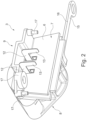
- the electrical adaptor 3 as can be seen in Fig. 1 and Fig. 2 , especially for an electric heat exchanger 2, has a base body 6 having a first side 7 and having a second side 8.
- the first side 7 of the base body 6 and the second side 8 of the base body 6 are located at the opposite sides of the base body 6.
- the base body 6 has a shape of a flat plate at which different features are arranged and located.
- the base body 6 is provided with a first electric interface 9 on the first side 7 and the base body 6 furthermore is provided with a second electric interface 10 on the second side 8.
- the first electric interface 9 is designed to be mechanically and electrically connected with a control unit 1 to allow a safe mechanical fastening of the electrical adaptor 3 to the control unit 1 and to allow a safe electric connection of the electrical adaptor 3 to the control unit 1.
- the electric connection of the electrical adaptor 3 to the control unit 1 can be realised directly to an electric cardboard 11 of the control unit 1.
- Such electric cardboard 11 of the control unit 1 might be the cardboard 11 carrying the electronic components of the control unit 1, e.g. electronic circuits, electronic switches, sensors etc.
- the second electric interface 10 is designed to be mechanically and electrically connected to a connector 4 of a power supply.
- This electric connection might be a plug-in connection, as can be seen in Fig. 1 .
- the mechanical connection might be a plug-in connection and/or a form-fitting connection, which can be realised alternatively or additionally by the use of screws or bolts to connect the body of the connector 4 to the electrical adaptor 3.
- the base body 6 comprises at least two bus bars 12 which intersect the base body 6 from the first side 7 to the second side 8 creating each electric connectors 13, 14 on the first side 7 and on the second side 8.
- the bus bars 12 connect the first side 7 with the second side 8 electrically.
- the connectors 13 on the first side 7 are designed as male connector elements, especially L-shaped male connector elements.
- the connectors 14 on the second side 8 are designed as female connector elements, especially clamp-shaped female connector elements.
- the base body 6 may further comprise a third bus bar 15 as ground bus bar which intersects the base body 6 from the first side 7 to the second side 8 creating an electric connector 16 on the first side 7 and on the second side 8.
- a third bus bar 15 as ground bus bar which intersects the base body 6 from the first side 7 to the second side 8 creating an electric connector 16 on the first side 7 and on the second side 8.
- the base body 6 comprises first mechanical connecting means 17 on the first side 7 for the connection of the base body 6 with the control unit 1 and the base body 6 further comprises second mechanical connecting means 18 on the second side 8 for the connection of the base body 6 with the connector 4 of a power supply.
- the base body 6 comprises a cylindrical hole 19 in which the female connector elements 14 are located. Additionally, the hole 19 has an open end or an opening on one side for the insertion of the connector 4 of the power supply. On the other side the hole 19 is closed by the base body 6.
- the first mechanical connecting means 17 are made as pin type elements which stick out from a plane of the base body 6.
- the plane is located at a right angle compared to the main body of the base body 6. Additionally, at least one through hole can be used as connecting means 17.
- the second mechanical connecting means 18 are made as through holes intersecting the base body 6.
- the base body 6 comprises a sealing interface 20 for a sealed connection with a housing 21 of the control unit 1.
- the housing 21 has a further sealing interface 22 which interacts with the sealing interface 20 of the base body 6. This design allows to integrate the base body 6 as part of the housing 21 of the control unit 1.
- the housing 21 is basically made of housing elements 23, e.g. like shells, which are mounted together and the base body 6 can sealingly be inserted in a free space to sealingly complete and close the housing 21.
- FIG. 3 shows a perspective representation of an arrangement of a control unit 1 of an electric heat exchanger 2 with an electrical adaptor 3 to allow an electrical and mechanical connection of a connector 4 of a power supply, especially a high-voltage (HV) connection or a low-voltage (LV) connection.
- HV high-voltage
- LV low-voltage
- the electric heat exchanger 2 displays heating means 5 and radiator means 24.
- the heating means 5 are arranged in a staggering relationship with the radiator means 24 such that each heating means 5 has on both sides arranged a radiator means 24 to allow better heat transfer to the radiator means 24 and from the radiator means 24 to the air flow flowing through the radiator means 24.
- the radiator means 24 is e.g. made as corrugated fin element as can be seen in Figure 3 .
- Figure 4 shows a further embodiment of an electrical adaptor 3 having a design with an angle of 90° between the first side 7 and the second side 8.
- the other features of the electrical adaptor 3 are almost identical to the electrical adaptor 3 according to Figures 1 and 2 .
- the two sides of the base body 6 are located at an angle of 90° and they can be arranged even in another arrangement. As can be seen, they are located on opposite sides of the base body 6.
Landscapes
- Engineering & Computer Science (AREA)
- Physics & Mathematics (AREA)
- Thermal Sciences (AREA)
- Mechanical Engineering (AREA)
- General Engineering & Computer Science (AREA)
- Air-Conditioning For Vehicles (AREA)
- Connector Housings Or Holding Contact Members (AREA)
Abstract
The invention relates to an electrical adaptor (3), especially for an electric heat exchanger (2), having a base body (6) having a first side (7) and having a second side (8), the first side (7) of the base body (6) and the second side (8) of the base body (6) are located at the opposite sides of the base body (6), the base body (6) is provided with a first electric interface (9) on the first side (7) and the base body (6) is provided with a second electric interface (10) on the second side (8), the first electric interface (9) is designed to be mechanically and electrically connected with a control unit (1) whereas the second electric interface (10) is designed to be mechanically and electrically connected to a connector (4) of a power supply, whereas the base body (6) comprises at least two bus bars (12) which intersect the base body (6) from the first side (7) to the second side (8) creating each electric connectors (13, 14) on the first side (7) and on the second side (8). The invention further relates to an electric heat exchanger (2) having an electric adaptor.
Description
- The invention relates to an electrical adaptor, especially for an electric heat exchanger, especially for a motor vehicle.
- Motor vehicles, especially electric driven motor vehicles have a need for electric heat exchangers to heat up the vehicle interior. Such electric heat exchangers are basically low-voltage applications or high-voltage applications depending on the provided heating power or the available electrical power supply within the motor vehicle.
- It has been shown that the electrical connection of such an electric heat exchanger by way of electric connectors varies from car manufacturer to car manufacturer or from application to application such that the manufacturer of such electric heat exchangers has to cope with different designs of electric connectors for different projects. This means that the design of the electric connector of an electric heat exchanger has specifically to be designed for every application to be able to be used with the electric connector to be used by the car manufacturer for this specific application. This leads to an increased design work, additional tooling costs and over all to higher costs of the electric heater.
- It is the aim of the invention to create a solution to allow a reduction of costs regarding the manufacturing of the electric heat exchanger.
- The aim is solved by an adaptor with the features of claim 1.
- One exemplary embodiment of the invention relates to an electrical adaptor, especially for an electric heat exchanger, having a base body having a first side and having a second side, the first side of the base body and the second side of the base body are located at the opposite sides of the base body, the base body is provided with a first electric interface on the first side and the base body is provided with a second electric interface on the second side, the first electric interface is designed to be mechanically and electrically connected with a control unit whereas the second electric interface is designed to be mechanically and electrically connected to a connector of a power supply, whereas the base body comprises at least two bus bars which intersect the base body from the first side to the second side creating each electric connectors on the first side and on the second side. An adaptor according to such features allows to connect e.g. a control unit to an external power supply and additionally allows to be a cost reduced solution.
- According to an embodiment of the invention it is of advantage that the base body further comprises a third bus bar as a ground bus bar which intersects the base body from the first side to the second side creating an electric connector on the first side and on the second side. Therefore, the bus bars allow the electrical connection between the control unit and the connector of a power source.
- According to another embodiment it is of advantage that the base body comprises first mechanical connecting means on the first side for the connection of the base body with the control unit and the base body further comprises second mechanical connecting means on the second side for the connection of the base body with the connector of a power supply. Therefore, the base body further comprises mechanical connection means on the first side for the mechanical fastening of the adaptor to the control unit, especially to a housing of the control unit. Furthermore, the base body comprises mechanical connecting means on the second side to allow a mechanical connection of the adaptor to the connector of the power supply. This prevents loosing the connection to the connector e.g. due to vibrations.
- Furthermore, it is of advantage that the connectors on the first side are male connector elements, especially L-shaped male connector elements and/or the connectors on the second side are female connector elements, especially clamp-shaped female connector elements. The male type connectors of the first side allow a quick and safe direct connection to e.g. a cardboard of the control unit. The L-shaped design allows a connection to a cardboard from the top while reaching through the base body in a horizontal direction. The female type connectors of the second side allow a quick connection to a male connector of the power source.
- Additionally, it is of advantage that the base body comprises a cylindrical hole in which the female connector elements are located and wherein the hole has an opening on one side for the insertion of the connector of the power supply. This design allows a penetration of the connector of the power supply within the hole to allow a firm and safe mechanical connection and a firm and durable electrical connection even under applied mechanical stress.
- A further embodiment of the invention provides a solution that the first mechanical connecting means are made as pin type elements which stick out from a plane of the base body. This solution allows a quick and durable fastening of the adaptor to the control unit, e.g. to the housing of the control unit and it is of advantage that the direction of movement of the adaptor during the fastening process is the same as for generating the electrical connection with the connectors on the first side.
- Furthermore, it is of advantage that the second mechanical connecting means are made as through holes intersecting the base body. This allows a fast connection of the connector to the base body e.g. by way of screws or bolts.
- Additionally, it is of advantage that the base body comprises a sealing interface for a sealed connection with a housing of the control unit. Therefore, the base body of the adaptor can be used as part of a wall structure of the housing of the control unit and the base body can be integrated to the housing in a sealed manner.
- The aim concerning the electric heat exchanger is solved with the features of
claim 9. - An exemplary embodiment of the invention relates to an electric heat exchanger having heating means and a control unit for the control of the heating means whereas the control unit comprises an electrical adaptor according to the invention to allow an electrical and mechanical connection to a connector of a power supply and to allow a cost reduced manufacturing of the heat exchanger.
- According to an embodiment of the invention it is of advantage that the control unit comprises a housing with at least one housing element which is in sealing contact with the adaptor at the sealing interface of the adaptor. This allows the sealed integration of the adaptor to the control unit preventing the intrusion of water and dirt into the control unit at the interface between the base body and the control unit.
- Further advantageous designs are described by the following description of the figures and by the dependent claims.
- In the following, the invention will be further explained based on several example embodiments using the drawing figures.
- In the figures:
- Fig. 1
- is a perspective representation of a control unit with an embodiment of an inventive adaptor,
- Fig. 2
- is a perspective representation of an adaptor according to
Fig. 1 , - Fig. 3
- is a perspective representation of a control unit with another embodiment of an inventive adaptor, and
- Fig. 4
- is a perspective representation of another adaptor.
-
Figure 1 shows a perspective representation of an arrangement of a control unit 1 of anelectric heat exchanger 2 with anelectrical adaptor 3 to allow an electrical and mechanical connection of aconnector 4 of a power supply, especially a high-voltage (HV) connection or a low-voltage (LV) connection. - The
electric heat exchanger 2 has electric heating means 5 for heating e.g. air or another fluid in order to heat e.g. the cabin of a motor vehicle or other components e.g. a battery of a motor vehicle. Therefore, theelectric heat exchanger 2 might be integrated in an air-conditioning unit of a motor vehicle and/or in a fluid circuit for the supply of components for heating such components. - The
electric heat exchanger 2 further provides the control unit 1 for the control of the electric heating means 5. - In an exemplary embodiment of the invention the heating means 5 and the control unit 1 are connected such that they build a unit which can be installed as a single piece in a motor vehicle.
- The
electrical adaptor 3, as can be seen inFig. 1 andFig. 2 , especially for anelectric heat exchanger 2, has abase body 6 having afirst side 7 and having asecond side 8. Thefirst side 7 of thebase body 6 and thesecond side 8 of thebase body 6 are located at the opposite sides of thebase body 6. Thebase body 6 has a shape of a flat plate at which different features are arranged and located. - The
base body 6 is provided with a firstelectric interface 9 on thefirst side 7 and thebase body 6 furthermore is provided with a secondelectric interface 10 on thesecond side 8. - The first
electric interface 9 is designed to be mechanically and electrically connected with a control unit 1 to allow a safe mechanical fastening of theelectrical adaptor 3 to the control unit 1 and to allow a safe electric connection of theelectrical adaptor 3 to the control unit 1. According to an aspect of the inventive embodiment the electric connection of theelectrical adaptor 3 to the control unit 1 can be realised directly to anelectric cardboard 11 of the control unit 1. Suchelectric cardboard 11 of the control unit 1 might be thecardboard 11 carrying the electronic components of the control unit 1, e.g. electronic circuits, electronic switches, sensors etc. - The second
electric interface 10 is designed to be mechanically and electrically connected to aconnector 4 of a power supply. This electric connection might be a plug-in connection, as can be seen inFig. 1 . The mechanical connection might be a plug-in connection and/or a form-fitting connection, which can be realised alternatively or additionally by the use of screws or bolts to connect the body of theconnector 4 to theelectrical adaptor 3. - As can be seen in
Fig. 2 thebase body 6 comprises at least twobus bars 12 which intersect thebase body 6 from thefirst side 7 to thesecond side 8 creating eachelectric connectors first side 7 and on thesecond side 8. Thebus bars 12 connect thefirst side 7 with thesecond side 8 electrically. - The
connectors 13 on thefirst side 7 are designed as male connector elements, especially L-shaped male connector elements. Theconnectors 14 on thesecond side 8 are designed as female connector elements, especially clamp-shaped female connector elements. - Optionally, the
base body 6 may further comprise athird bus bar 15 as ground bus bar which intersects thebase body 6 from thefirst side 7 to thesecond side 8 creating anelectric connector 16 on thefirst side 7 and on thesecond side 8. - Furthermore, the
base body 6 comprises first mechanical connecting means 17 on thefirst side 7 for the connection of thebase body 6 with the control unit 1 and thebase body 6 further comprises second mechanical connecting means 18 on thesecond side 8 for the connection of thebase body 6 with theconnector 4 of a power supply. - It can be seen in
Fig. 1 that thebase body 6 comprises acylindrical hole 19 in which thefemale connector elements 14 are located. Additionally, thehole 19 has an open end or an opening on one side for the insertion of theconnector 4 of the power supply. On the other side thehole 19 is closed by thebase body 6. - The first mechanical connecting means 17 are made as pin type elements which stick out from a plane of the
base body 6. The plane is located at a right angle compared to the main body of thebase body 6. Additionally, at least one through hole can be used as connectingmeans 17. - The second mechanical connecting means 18 are made as through holes intersecting the
base body 6. - According to another aspect of the invention, the
base body 6 comprises a sealinginterface 20 for a sealed connection with ahousing 21 of the control unit 1. Thehousing 21 has a further sealinginterface 22 which interacts with the sealinginterface 20 of thebase body 6. This design allows to integrate thebase body 6 as part of thehousing 21 of the control unit 1. - The
housing 21 is basically made ofhousing elements 23, e.g. like shells, which are mounted together and thebase body 6 can sealingly be inserted in a free space to sealingly complete and close thehousing 21. -
Figure 3 shows a perspective representation of an arrangement of a control unit 1 of anelectric heat exchanger 2 with anelectrical adaptor 3 to allow an electrical and mechanical connection of aconnector 4 of a power supply, especially a high-voltage (HV) connection or a low-voltage (LV) connection. - In
Figure 3 theelectric heat exchanger 2 displays heating means 5 and radiator means 24. The heating means 5 are arranged in a staggering relationship with the radiator means 24 such that each heating means 5 has on both sides arranged a radiator means 24 to allow better heat transfer to the radiator means 24 and from the radiator means 24 to the air flow flowing through the radiator means 24. The radiator means 24 is e.g. made as corrugated fin element as can be seen inFigure 3 . -
Figure 4 shows a further embodiment of anelectrical adaptor 3 having a design with an angle of 90° between thefirst side 7 and thesecond side 8. The other features of theelectrical adaptor 3 are almost identical to theelectrical adaptor 3 according toFigures 1 and2 . For reference see the respective description above. In the design ofFigure 4 the two sides of thebase body 6 are located at an angle of 90° and they can be arranged even in another arrangement. As can be seen, they are located on opposite sides of thebase body 6.
Claims (10)
- An electrical adaptor (3), especially for an electric heat exchanger (2), having a base body (6) having a first side (7) and having a second side (8), the first side (7) of the base body (6) and the second side (8) of the base body (6) are located at the opposite sides of the base body (6), the base body (6) is provided with a first electric interface (9) on the first side (7) and the base body (6) is provided with a second electric interface (10) on the second side (8), the first electric interface (9) is designed to be mechanically and electrically connected with a control unit (1) whereas the second electric interface (10) is designed to be mechanically and electrically connected to a connector (4) of a power supply, characterised in that the base body (6) comprises at least two bus bars (12) which intersect the base body (6) from the first side (7) to the second side (8) creating each electric connectors (13, 14) on the first side (7) and on the second side (8).
- The electrical adaptor (3) according to claim 1, characterised in that the base body (6) further comprises a third bus bar (15) as ground bus bar which intersects the base body (6) from the first side (7) to the second side (8) creating an electric connector (16) on the first side (7) and on the second side (8).
- The electrical adaptor (3) according to claims 1 or 2, characterised in that the base body (6) comprises first mechanical connecting means (17) on the first side (7) for the connection of the base body (6) with the control unit (1) and the base body (6) further comprises second mechanical connecting means (18) on the second side for the connection of the base body (6) with the connector (4) of a power supply.
- The electrical adaptor (3) according to claims 1, 2 or 3, characterised in that the electric connectors (13) on the first side (7) are male connector elements, especially L-shaped male connector elements and/or the electric connectors (14) on the second side (8) are female connector elements, especially clamp-shaped female connector elements.
- The electrical adaptor (3) according to claim 4, characterised in that the base body (6) comprises a cylindrical hole (19) in which the female connector elements are located and wherein the hole (19) has an opening on one side for the insertion of the connector (4) of the power supply.
- The electrical adaptor (3) according to claim 3 and/or 4, characterised in that the first mechanical connecting means (17) are made as pin type elements which stick out from a plane of the base body (6).
- The electrical adaptor (3) according to claim 3, 4 and/or 5, characterised in that the second mechanical connecting means (18) are made as through holes intersecting the base body (6).
- The electrical adaptor (3) according to one of the preceding claims, characterised in that the base body (6) comprises a sealing interface (20) for a sealed connection with a housing (21) of the control unit (1).
- A heat exchanger (2) having heating means (5) and a control unit (1) for the control of the heating means (5) characterised in that the control unit (1) comprises an electrical adaptor (3) according to at least one of the preceding claims.
- The heat exchanger (2) according to claim 9, characterised in that the control unit (1) comprises a housing (21) with at least one housing element (23) which is in sealing contact with the electrical adaptor (3) at the sealing interface (20) of the electrical adaptor (3).
Priority Applications (2)
| Application Number | Priority Date | Filing Date | Title |
|---|---|---|---|
| EP23216861.7A EP4572026A1 (en) | 2023-12-14 | 2023-12-14 | Electrical adaptor and electric heat exchanger |
| CN202411451352.9A CN120165264A (en) | 2023-12-14 | 2024-10-17 | Electric adapter and electric heat exchanger |
Applications Claiming Priority (1)
| Application Number | Priority Date | Filing Date | Title |
|---|---|---|---|
| EP23216861.7A EP4572026A1 (en) | 2023-12-14 | 2023-12-14 | Electrical adaptor and electric heat exchanger |
Publications (1)
| Publication Number | Publication Date |
|---|---|
| EP4572026A1 true EP4572026A1 (en) | 2025-06-18 |
Family
ID=89222980
Family Applications (1)
| Application Number | Title | Priority Date | Filing Date |
|---|---|---|---|
| EP23216861.7A Pending EP4572026A1 (en) | 2023-12-14 | 2023-12-14 | Electrical adaptor and electric heat exchanger |
Country Status (2)
| Country | Link |
|---|---|
| EP (1) | EP4572026A1 (en) |
| CN (1) | CN120165264A (en) |
Citations (7)
| Publication number | Priority date | Publication date | Assignee | Title |
|---|---|---|---|---|
| US20130069320A1 (en) * | 2011-09-21 | 2013-03-21 | Hitachi Automotive Systems, Ltd. | Seal Structure for Electronic Control Device |
| EP2884197A1 (en) * | 2013-12-13 | 2015-06-17 | Eberspächer catem GmbH & Co. KG | Electric heating device and method for its production |
| US20150251551A1 (en) * | 2014-03-04 | 2015-09-10 | Lear Corporation | Wall plug system for electric vehicle |
| US20160353563A1 (en) * | 2015-05-28 | 2016-12-01 | Yazaki Corporation | Heat dissipation structure for connector module |
| EP3480532A1 (en) * | 2017-11-02 | 2019-05-08 | Eberspächer catem GmbH & Co. KG | Electric heating device |
| EP3971492A1 (en) * | 2020-09-17 | 2022-03-23 | Mahle International GmbH | Electrical adapter |
| EP4246779A1 (en) * | 2022-03-18 | 2023-09-20 | MAHLE International GmbH | Electric power supply device for an electric motor |
-
2023
- 2023-12-14 EP EP23216861.7A patent/EP4572026A1/en active Pending
-
2024
- 2024-10-17 CN CN202411451352.9A patent/CN120165264A/en active Pending
Patent Citations (7)
| Publication number | Priority date | Publication date | Assignee | Title |
|---|---|---|---|---|
| US20130069320A1 (en) * | 2011-09-21 | 2013-03-21 | Hitachi Automotive Systems, Ltd. | Seal Structure for Electronic Control Device |
| EP2884197A1 (en) * | 2013-12-13 | 2015-06-17 | Eberspächer catem GmbH & Co. KG | Electric heating device and method for its production |
| US20150251551A1 (en) * | 2014-03-04 | 2015-09-10 | Lear Corporation | Wall plug system for electric vehicle |
| US20160353563A1 (en) * | 2015-05-28 | 2016-12-01 | Yazaki Corporation | Heat dissipation structure for connector module |
| EP3480532A1 (en) * | 2017-11-02 | 2019-05-08 | Eberspächer catem GmbH & Co. KG | Electric heating device |
| EP3971492A1 (en) * | 2020-09-17 | 2022-03-23 | Mahle International GmbH | Electrical adapter |
| EP4246779A1 (en) * | 2022-03-18 | 2023-09-20 | MAHLE International GmbH | Electric power supply device for an electric motor |
Also Published As
| Publication number | Publication date |
|---|---|
| CN120165264A (en) | 2025-06-17 |
Similar Documents
| Publication | Publication Date | Title |
|---|---|---|
| CN103477518B (en) | Current-carrying device | |
| KR101689784B1 (en) | Modular electrical plug connector assembly | |
| CN112272902A (en) | Electric power terminal for charging system | |
| US20120298163A1 (en) | Thermoelectric unit | |
| EP2428747B2 (en) | Heat exchanger | |
| CN114616931B (en) | Circuit structure | |
| US7952024B2 (en) | U-turn bus bar | |
| JP2007168773A (en) | Electric radiator | |
| EP2131117B1 (en) | Motor vehicle air conditioning with PTC heating device | |
| CN112272896A (en) | Wiring module | |
| CN113708123A (en) | Electric connecting device with cooling function | |
| CN109690079A (en) | Inverter-integrated type electric compressor and its manufacturing method | |
| EP2346304B1 (en) | Heat exchanger | |
| CN1972048B (en) | Holder | |
| KR102553090B1 (en) | Ptc heater | |
| CN120165264A (en) | Electric adapter and electric heat exchanger | |
| DE102025115588A1 (en) | Charging inlet arrangement of a vehicle | |
| US6179628B1 (en) | Electric connection box | |
| CN212046774U (en) | Electric heating device, heating, ventilation and/or air conditioning device and motor vehicle | |
| DE102024120368A1 (en) | charging inlet assembly with wiring harness | |
| JP7376535B2 (en) | Terminal block | |
| CN115379676B (en) | Motor controller and vehicle | |
| CN111619303A (en) | Heating device with housing assembly | |
| CN218827902U (en) | High-voltage switching box, motor controller and hybrid vehicle | |
| CN108029223B (en) | Apparatus for open-loop and/or closed-loop control of fan motors |
Legal Events
| Date | Code | Title | Description |
|---|---|---|---|
| PUAI | Public reference made under article 153(3) epc to a published international application that has entered the european phase |
Free format text: ORIGINAL CODE: 0009012 |
|
| STAA | Information on the status of an ep patent application or granted ep patent |
Free format text: STATUS: THE APPLICATION HAS BEEN PUBLISHED |
|
| AK | Designated contracting states |
Kind code of ref document: A1 Designated state(s): AL AT BE BG CH CY CZ DE DK EE ES FI FR GB GR HR HU IE IS IT LI LT LU LV MC ME MK MT NL NO PL PT RO RS SE SI SK SM TR |
|
| STAA | Information on the status of an ep patent application or granted ep patent |
Free format text: STATUS: REQUEST FOR EXAMINATION WAS MADE |
|
| 17P | Request for examination filed |
Effective date: 20251120 |