EP4572008A1 - Azimuthal steering antenna for side radar - Google Patents
Azimuthal steering antenna for side radar Download PDFInfo
- Publication number
- EP4572008A1 EP4572008A1 EP24168587.4A EP24168587A EP4572008A1 EP 4572008 A1 EP4572008 A1 EP 4572008A1 EP 24168587 A EP24168587 A EP 24168587A EP 4572008 A1 EP4572008 A1 EP 4572008A1
- Authority
- EP
- European Patent Office
- Prior art keywords
- top plate
- antenna assembly
- signal
- conductive top
- riser
- Prior art date
- Legal status (The legal status is an assumption and is not a legal conclusion. Google has not performed a legal analysis and makes no representation as to the accuracy of the status listed.)
- Pending
Links
Images

Classifications
-
- H—ELECTRICITY
- H01—ELECTRIC ELEMENTS
- H01Q—ANTENNAS, i.e. RADIO AERIALS
- H01Q1/00—Details of, or arrangements associated with, antennas
- H01Q1/27—Adaptation for use in or on movable bodies
- H01Q1/32—Adaptation for use in or on road or rail vehicles
- H01Q1/325—Adaptation for use in or on road or rail vehicles characterised by the location of the antenna on the vehicle
- H01Q1/3283—Adaptation for use in or on road or rail vehicles characterised by the location of the antenna on the vehicle side-mounted antennas, e.g. bumper-mounted, door-mounted
-
- H—ELECTRICITY
- H01—ELECTRIC ELEMENTS
- H01Q—ANTENNAS, i.e. RADIO AERIALS
- H01Q5/00—Arrangements for simultaneous operation of antennas on two or more different wavebands, e.g. dual-band or multi-band arrangements
- H01Q5/50—Feeding or matching arrangements for broad-band or multi-band operation
- H01Q5/55—Feeding or matching arrangements for broad-band or multi-band operation for horn or waveguide antennas
-
- H—ELECTRICITY
- H01—ELECTRIC ELEMENTS
- H01Q—ANTENNAS, i.e. RADIO AERIALS
- H01Q1/00—Details of, or arrangements associated with, antennas
- H01Q1/36—Structural form of radiating elements, e.g. cone, spiral, umbrella; Particular materials used therewith
- H01Q1/38—Structural form of radiating elements, e.g. cone, spiral, umbrella; Particular materials used therewith formed by a conductive layer on an insulating support
-
- H—ELECTRICITY
- H01—ELECTRIC ELEMENTS
- H01Q—ANTENNAS, i.e. RADIO AERIALS
- H01Q1/00—Details of, or arrangements associated with, antennas
- H01Q1/12—Supports; Mounting means
-
- H—ELECTRICITY
- H01—ELECTRIC ELEMENTS
- H01Q—ANTENNAS, i.e. RADIO AERIALS
- H01Q1/00—Details of, or arrangements associated with, antennas
- H01Q1/27—Adaptation for use in or on movable bodies
- H01Q1/32—Adaptation for use in or on road or rail vehicles
-
- H—ELECTRICITY
- H01—ELECTRIC ELEMENTS
- H01Q—ANTENNAS, i.e. RADIO AERIALS
- H01Q1/00—Details of, or arrangements associated with, antennas
- H01Q1/27—Adaptation for use in or on movable bodies
- H01Q1/32—Adaptation for use in or on road or rail vehicles
- H01Q1/3208—Adaptation for use in or on road or rail vehicles characterised by the application wherein the antenna is used
- H01Q1/3233—Adaptation for use in or on road or rail vehicles characterised by the application wherein the antenna is used particular used as part of a sensor or in a security system, e.g. for automotive radar, navigation systems
-
- H—ELECTRICITY
- H01—ELECTRIC ELEMENTS
- H01Q—ANTENNAS, i.e. RADIO AERIALS
- H01Q1/00—Details of, or arrangements associated with, antennas
- H01Q1/50—Structural association of antennas with earthing switches, lead-in devices or lightning protectors
-
- H—ELECTRICITY
- H01—ELECTRIC ELEMENTS
- H01Q—ANTENNAS, i.e. RADIO AERIALS
- H01Q13/00—Waveguide horns or mouths; Slot antennas; Leaky-waveguide antennas; Equivalent structures causing radiation along the transmission path of a guided wave
- H01Q13/02—Waveguide horns
-
- H—ELECTRICITY
- H01—ELECTRIC ELEMENTS
- H01Q—ANTENNAS, i.e. RADIO AERIALS
- H01Q13/00—Waveguide horns or mouths; Slot antennas; Leaky-waveguide antennas; Equivalent structures causing radiation along the transmission path of a guided wave
- H01Q13/02—Waveguide horns
- H01Q13/0233—Horns fed by a slotted waveguide array
-
- H—ELECTRICITY
- H01—ELECTRIC ELEMENTS
- H01Q—ANTENNAS, i.e. RADIO AERIALS
- H01Q21/00—Antenna arrays or systems
- H01Q21/06—Arrays of individually energised antenna units similarly polarised and spaced apart
- H01Q21/061—Two dimensional planar arrays
- H01Q21/064—Two dimensional planar arrays using horn or slot aerials
-
- H—ELECTRICITY
- H01—ELECTRIC ELEMENTS
- H01Q—ANTENNAS, i.e. RADIO AERIALS
- H01Q3/00—Arrangements for changing or varying the orientation or the shape of the directional pattern of the waves radiated from an antenna or antenna system
- H01Q3/02—Arrangements for changing or varying the orientation or the shape of the directional pattern of the waves radiated from an antenna or antenna system using mechanical movement of antenna or antenna system as a whole
Definitions
- the present disclosure relates to an azimuthal steering antenna for a side radar.
- Radar uses electromagnetic signals to detect and track objects.
- the electromagnetic signals are transmitted and received using one or more antennas.
- An antenna may be characterized in terms of gain and beam width, or more specifically pattern, which is a measure of the gain as a function of direction.
- the antenna may be customized for a specific application. For example, the radiation pattern may be offset from center for a side radar application.
- the present disclosure includes, in various features, an antenna assembly configured to steer a radio frequency (RF) signal to a focus area offset from an azimuth center.
- the antenna assembly includes: a circuit board including an integrated circuit configured to process the RF signal, and a conductive trace extending from the integrated circuit; a waveguide plate over the circuit board, the waveguide plate including a waveguide configured to guide the RF signal at least one of to and from the conductive trace; and a conductive top plate over the waveguide plate.
- RF radio frequency
- the conductive top plate includes: an outer surface and an inner surface facing the waveguide plate, the outer surface is opposite to the inner surface; a feed horn defined by the conductive top plate between the inner surface and the outer surface, the feed horn is aligned with the waveguide; a first surface and a second surface of the feed horn that is opposite to the first surface, the first surface is angled towards the focus area; and a step defined by the conductive top plate extending from the first surface to the outer surface towards the focus area, the step configured to steer the RF signal to emanate from the outer surface of the conductive top plate towards the focus area.
- the feed horn is normal to the outer surface of the conductive top plate.
- the second surface of the feed horn is angled away from the first surface.
- the focus area is 60° offset from the azimuth center.
- the antenna assembly is configured as a side antenna for a vehicle.
- the step includes a tread surface extending parallel to the outer surface of the conductive top plate.
- the step includes a riser surface extending away from a tread surface towards the outer surface of the conductive top plate.
- the step includes: a tread surface extending parallel to the outer surface of the conductive top plate; a riser surface extending away from the tread surface towards the outer surface of the conductive top plate; a first curved surface extending from the first surface of the feed horn to the tread surface; a second curved surface between the tread surface and the riser surface; and a third curved surface between the riser surface and the outer surface.
- a fourth curved surface is between the second surface of the feed horn and the outer surface.
- the step includes a tread surface and a riser surface, the tread surface has a depth that is greater than a height of the riser surface.
- the step includes a tread surface and a riser surface; the tread surface has a depth of between 0.25 and 0.5 of a wavelength of the RF signal; and the riser surface has a height of 0.25 of the wavelength of the RF signal.
- the tread surface has a depth of 1.42mm; and the riser surface has a height of 1.0mm.
- the feed horn has a maximum width between the first surface and the second surface of 0.25 of a wavelength of the RF signal.
- the present disclosure further includes, in various features, an antenna assembly configured to steer a radio frequency (RF) signal to a focus area offset from an azimuth center.
- the antenna assembly includes: a circuit board including an integrated circuit configured to process the RF signal, and a conductive trace extending from the integrated circuit; a waveguide plate over the circuit board, the waveguide plate including a waveguide configured to guide the RF signal at least one of to and from the conductive trace; and a conductive top plate over the waveguide plate.
- RF radio frequency
- the conductive top plate includes: an outer surface and an inner surface facing the waveguide plate, the outer surface is opposite to the inner surface; a feed horn defined by the conductive top plate; and a step defined by the conductive top plate adjacent to the feed horn, the step including a tread surface and a riser surface extending from the tread surface towards the outer surface of the conductive top plate.
- the tread surface extends parallel to the outer surface.
- the focus area is at least 60° offset from the azimuth center.
- the tread surface has a depth that is greater than a height of the riser surface.
- the tread surface has a depth of between 0.25 and 0.5 of a wavelength of the RF signal; and the riser surface has a height of 0.25 of the wavelength of the RF signal.
- the tread surface has a depth of 1.42mm; and the riser surface has a height of 1.0mm.
- the present disclosure also includes, in various features, an antenna assembly configured to steer a radio frequency (RF) signal to a focus area offset from an azimuth center.
- the antenna assembly includes: a circuit board including an integrated circuit configured to process the RF signal, and a conductive trace extending from the integrated circuit; a waveguide plate over the circuit board, the waveguide plate including a waveguide configured to guide the RF signal at least one of to and from the conductive trace; and a conductive top plate over the waveguide plate.
- RF radio frequency
- the conductive top plate includes: an outer surface and an inner surface facing the waveguide plate, the outer surface is opposite to the inner surface; a feed horn defined by the conductive top plate between the inner surface and the outer surface, the feed horn is aligned with the waveguide; a first surface and a second surface of the feed horn, the first surface is opposite to the second surface and is angled towards the focus area away from the second surface; and a step defined by the conductive top plate extending towards the focus area from the first surface to the outer surface, the step including a tread surface and a riser surface configured to steer the RF signal to emanate from the outer surface of the conductive top plate towards the focus area.
- the tread surface has a depth of between 0.25 and 0.5 of a wavelength of the RF signal; and the riser surface has a height of 0.25 of the wavelength of the RF signal.
- Side radars may be configured to steer radio frequency (RF) signals towards a particular area to optimize performance.
- RF radio frequency
- the present disclosure provides for an antenna assembly configured to steer the RF signals to a focus area offset from an azimuth center of the antenna assembly.
- a conductive top plate of the antenna assembly defines a feed horn, and a step extending from the feed horn to an outer surface of the top plate.
- the step is configured to steer the RF signals to emanate from the outer surface towards the focus area.
- the step includes a tread surface and a riser surface.
- the step may be formed with a tread surface and a riser surface of any suitable dimensions to generate a customized radiation pattern suitable for a particular application. For example, the depth of the tread surface and height of the riser surface may be varied to customize the radiation pattern, as explained herein.
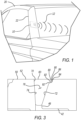
- FIGS. 1 and 2 illustrate an exemplary antenna assembly 10 in accordance with the present disclosure.
- the antenna assembly 10 is configured for use in any suitable application, such as an automotive application.
- the antenna assembly 10 is mounted to a vehicle 20.
- the antenna assembly 10 may be mounted to any suitable location of the vehicle 20, such as on an A-pillar 22 of the vehicle 20.
- the antenna assembly 10 is configured to transmit and/or receive radio frequency (RF) signals 12 to a focus area offset from an azimuth center of the antenna assembly.
- RF radio frequency
- the RF signals 12 are directed towards a focus area at a front of the vehicle 20, even though a conductive top plate of the antenna assembly 10 faces towards a side of the vehicle 20, or towards a front corner of the vehicle 20.
- the antenna assembly 10 may be configured for any other suitable automotive or non-automotive use as well.
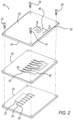
- the antenna assembly 10 generally includes a circuit board 30, a waveguide plate 40, and a conductive top plate 50.
- the circuit board 30, the waveguide plate 40, and the conductive top plate 50 are secured together in any suitable manner, such as with any suitable fasteners 24.
- the waveguide plate 40 is secured between the circuit board 30 and the conductive top plate 50.
- the circuit board 30 includes an integrated circuit (IC) 32 configured to process radio frequency (RF) signals. Extending from the IC 32 are conductive traces 34, which are electrically connected to the IC 32. Conductive pads 36 are at distal ends of the traces 34. The pads 36 and the traces 34 are configured to electrically conduct RF signals to and from the IC 32.
- IC integrated circuit
- RF radio frequency
- the waveguide plate 40 defines a plurality of waveguides 42.
- the waveguides 42 extend from feeding holes 44.
- the feeding holes 44 are aligned with the pads 36 of the circuit board 30.
- RF signals transmitted from the IC 32 are conducted along the traces 34 to the pads 36, and through the feeding holes 44 of the waveguide plate 40 to the waveguides 42.
- received RF signals are directed by the waveguides 42 to the feeding holes 44 and to the IC 32 by way of the pads 36 and the traces 34.
- Distal ends 46 of the waveguides 42 opposite to the feeding holes 44 are positioned and shaped to align with feed horns 70 of the conductive top plate 50.
- Each one of the distal ends 46 may include multiple branch ends. Each branch end may be aligned with a different feed horn 70. In some applications, more than one branch end of the multiple branches may be aligned with the same feed horn 70.
- the conductive top plate 50 has an outer surface 52 and an inner surface 54.
- the outer surface 52 is opposite to the inner surface 54.
- the inner surface 54 faces the waveguide plate 40.
- the outer surface 52 is an outer surface of the antenna assembly 10.
- the conductive top plate 50 is made of any suitable conductive material, such as any suitable metallic material.
- the conductive top plate 50 defines a plurality of slots 60, each of which are openings of a different feed horn 70.
- FIG. 3 is a cross-sectional view of one of the feed horns 70.
- the feed horns 70 are normal to the outer surface 52 and configured to direct transmitted RF signals to the focus area offset from the azimuth center of the antenna assembly 10, as explained herein.
- the feed horns 70 are also configured to direct received RF signals to the distal ends 46 of the waveguides 42.
- the feed horns 70 may be symmetric or asymmetric.
- Each feed horn 70 includes a first surface 72 and a second surface 74.
- the first and the second surfaces 72 and 74 extend away from the distal end 46 of the waveguide 42 towards the outer surface 52 of the conductive top plate 50.
- the first surface 72 is opposite to the second surface 74.
- the first and the second surfaces 72, 74 are connected by side surfaces 76.
- the first and the second surfaces 72, 74 may be generally symmetrical whereby the first and the second surfaces 72, 74 extend generally parallel to each other. In other applications, the first and the second surfaces 72, 74 may be asymmetrical.
- the first surface 72 is angled away from the second surface 74 towards the focus area.
- the first surface 72 is angled in a direction in which the RF signals 12 are to be steered.
- the first surface 72 terminates prior to reaching the outer surface 52.
- the conductive top plate 50 also defines a step 80, which extends from the first surface 72 to the outer surface 52.
- the step 80 also extends towards the focus area.
- the step 80 is configured to steer the RF signal 12 to emanate from the outer surface 52 of the conductive top plate 50 towards the focus area, as explained further herein and generally illustrated in FIG. 5 .
- the step 80 includes a tread surface 82 and a riser surface 84.
- the tread surface 82 extends parallel to, or generally parallel to, the outer surface 52.
- the riser surface 84 extends away from the tread surface 82 towards the outer surface 52 of the conductive top plate 50.
- the riser surface 84 may be at a right angle to the tread surface 82, or angled away from the tread surface 82.
- the riser surface 84 may be angled to extend along a line that is parallel to, or generally parallel to, the first surface 72.
- the step 80 may further include a third curved surface extending from the riser surface 84 to the outer surface 52. As shown in the example of FIG. 4 , a fourth curved surface 96 may extend from the second surface 74 to the outer surface 52.
- the feed horns 70 may be formed with any customized dimensions suitable to steer the RF signals 12 towards the focus area offset from the azimuth center of the antenna assembly 10.
- the feed horn 70 may be formed with any suitable maximum distance A between the first surface 72 and the second surface 74.
- the tread surface 82 may be formed with any suitable depth B from the first surface 72 to the riser surface 84.
- the riser surface 84 may be formed with any suitable height C from the tread surface 82 to the outer surface 52.
- the maximum distance A of the feed horn 70 between the first surface 72 and the second surface 74 may be one-quarter of the wavelength of the RF signal 12, which may be 1.0 mm, for example.
- the tread surface 82 may be formed with depth B of between one-quarter and one-half of a wavelength of the RF signal 12.
- the tread surface 82 may have a depth B of 1.42 mm.
- the riser surface 84 may have a height C that is one-quarter of the wavelength of the RF signal 12.
- the riser surface 84 may have a height C of 1.0 mm.
- feed horn 70 and the step 80 are suitable, in some applications, to focus the RF signal 12 to be offset from the azimuth center by 60°, or about 60°, for example.
- the feed horn 70 and the step 80 may be formed with any other suitable dimensions to focus the RF signal 12 to an area offset from the azimuth center at any other suitable angle as well.
- FIG. 5 illustrates an exemplary RF signal 12 emanating from the feed horn 70 along the step 80 to the focus area offset from the azimuth center of the antenna assembly 10.
- the feed horn 70 and the step 80 cause the RF signal 12 to be delayed in the positive X-direction identified in FIG. 5 . This delay in field propagation effectively steers the RF signal 12 to the focus area offset from the azimuth center.
- the height C of the riser surface 84 may also be customized to vary the radiation pattern of the RF signal 12. Generally, the greater the height C, and thus the higher the riser surface 84 extends in the Z direction, the more space there is for the RF signal 12 propagation to become even by the final aperture at the slot 60, which thereby reduces the beam steering. Conversely, if the riser surface 84 is too tall along line C, there may not be enough of a potential for the RF signal 12 to couple through the step 80. Providing the riser surface 84 with a height C that is one-quarter of a wavelength of the RF signal 12, such as 1 mm, may be suitable for a range of side radar applications.
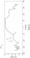
- FIG. 6 illustrates exemplary radiation patterns 110 of the antenna assembly 10.
- Radiation pattern A is generated by the antenna assembly 10 when the tread surface 82 is provided with a depth B that is just under half a wavelength of the RF signal 12, which may be 1.42 mm, or about 1.42 mm, for example.
- radiation pattern A is generated when the riser surface 84 is provided with a height C that is 1 mm.
- Radiation pattern B results when the tread surface 82 is formed with a relatively shorter depth B.
- Radiation pattern C results when the tread surface 82 is formed with a relatively longer depth B.
- the radiation patterns represent the tuneability of the antenna assembly 10.
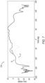
- FIG. 7 illustrates additional exemplary radiation patterns 210 of the antenna assembly 10.
- Radiation pattern A' is generated by the antenna assembly 10 when the riser surface 84 has a height C of one-quarter of a wavelength of the RF signal 12, which may be 1.0 mm, or about 1.0 mm., for example.
- radiation pattern A' is generated when the tread surface 82 is provided with a depth B that is 2 mm.
- Radiation pattern B' results when the riser surface 84 is formed with a relatively shorter height C.
- Radiation pattern C' results when the riser surface 84 is formed with a relatively taller height C.
- the radiation patterns represent the tuneability of the antenna assembly 10.
- the antenna assembly 10 may thus be configured to steer the RF signal 12 to a focus area offset from the azimuth center of the antenna assembly 10.
- the feed horn 70 and the step 80 may be formed with any suitable dimensions to customize the radiation pattern to be offset any suitable distance from the azimuth center.
- Example embodiments are provided so that this disclosure will be thorough, and will fully convey the scope to those who are skilled in the art. Numerous specific details are set forth such as examples of specific components, devices, and methods, to provide a thorough understanding of embodiments of the present disclosure. It will be apparent to those skilled in the art that specific details need not be employed, that example embodiments may be embodied in many different forms and that neither should be construed to limit the scope of the disclosure. In some example embodiments, well-known processes, well-known device structures, and well-known technologies are not described in detail.
- first, second, third, etc. may be used herein to describe various elements, components, regions, layers and/or sections, these elements, components, regions, layers and/or sections should not be limited by these terms. These terms may be only used to distinguish one element, component, region, layer or section from another region, layer or section. Terms such as “first,” “second,” and other numerical terms when used herein do not imply a sequence or order unless clearly indicated by the context. Thus, a first element, component, region, layer or section discussed below could be termed a second element, component, region, layer or section without departing from the teachings of the example embodiments.
- spatially relative terms such as “inner,” “outer,” “beneath,” “below,” “lower,” “above,” “upper,” and the like, may be used herein for ease of description to describe one element or feature's relationship to another element(s) or feature(s) as illustrated in the figures.
- Spatially relative terms may be intended to encompass different orientations of the device in use or operation in addition to the orientation depicted in the figures. For example, if the device in the figures is turned over, elements described as “below” or “beneath” other elements or features would then be oriented “above” the other elements or features.
- the example term “below” can encompass both an orientation of above and below.
- the device may be otherwise oriented (rotated 90 degrees or at other orientations) and the spatially relative descriptors used herein interpreted accordingly.
Landscapes
- Engineering & Computer Science (AREA)
- Remote Sensing (AREA)
- Computer Security & Cryptography (AREA)
- Radar, Positioning & Navigation (AREA)
- Waveguide Aerials (AREA)
- Details Of Aerials (AREA)
Abstract
An antenna assembly configured to steer a radio frequency (RF) signal to a focus area offset from an azimuth center. The antenna assembly includes a feed horn defined by a conductive top plate between an inner surface and an outer surface of the plate. The feed horn is aligned with a waveguide. A step is defined by the conductive top plate extending from a surface of the feed horn towards the focus area. The step is configured to steer the RF signal to emanate from the outer surface of the conductive top plate towards the focus area.
Description
- The present disclosure relates to an azimuthal steering antenna for a side radar.
- This section provides background information related to the present disclosure, which is not necessarily prior art.
- Radar uses electromagnetic signals to detect and track objects. The electromagnetic signals are transmitted and received using one or more antennas. An antenna may be characterized in terms of gain and beam width, or more specifically pattern, which is a measure of the gain as a function of direction. By modifying the radiation pattern, the antenna may be customized for a specific application. For example, the radiation pattern may be offset from center for a side radar application.
- This section provides a general summary of the disclosure, and is not a comprehensive disclosure of its full scope or all of its features.
- The present disclosure includes, in various features, an antenna assembly configured to steer a radio frequency (RF) signal to a focus area offset from an azimuth center. The antenna assembly includes: a circuit board including an integrated circuit configured to process the RF signal, and a conductive trace extending from the integrated circuit; a waveguide plate over the circuit board, the waveguide plate including a waveguide configured to guide the RF signal at least one of to and from the conductive trace; and a conductive top plate over the waveguide plate. The conductive top plate includes: an outer surface and an inner surface facing the waveguide plate, the outer surface is opposite to the inner surface; a feed horn defined by the conductive top plate between the inner surface and the outer surface, the feed horn is aligned with the waveguide; a first surface and a second surface of the feed horn that is opposite to the first surface, the first surface is angled towards the focus area; and a step defined by the conductive top plate extending from the first surface to the outer surface towards the focus area, the step configured to steer the RF signal to emanate from the outer surface of the conductive top plate towards the focus area.
- In further features, the feed horn is normal to the outer surface of the conductive top plate.
- In further features, the second surface of the feed horn is angled away from the first surface.
- In further features, the focus area is 60° offset from the azimuth center.
- In further features, the antenna assembly is configured as a side antenna for a vehicle.
- In further features, the step includes a tread surface extending parallel to the outer surface of the conductive top plate.
- In further features, the step includes a riser surface extending away from a tread surface towards the outer surface of the conductive top plate.
- In further features, the step includes: a tread surface extending parallel to the outer surface of the conductive top plate; a riser surface extending away from the tread surface towards the outer surface of the conductive top plate; a first curved surface extending from the first surface of the feed horn to the tread surface; a second curved surface between the tread surface and the riser surface; and a third curved surface between the riser surface and the outer surface.
- In further features, a fourth curved surface is between the second surface of the feed horn and the outer surface.
- In further features, the step includes a tread surface and a riser surface, the tread surface has a depth that is greater than a height of the riser surface.
- In further features, the step includes a tread surface and a riser surface; the tread surface has a depth of between 0.25 and 0.5 of a wavelength of the RF signal; and the riser surface has a height of 0.25 of the wavelength of the RF signal.
- In further features, the tread surface has a depth of 1.42mm; and the riser surface has a height of 1.0mm.
- In further features, the feed horn has a maximum width between the first surface and the second surface of 0.25 of a wavelength of the RF signal.
- The present disclosure further includes, in various features, an antenna assembly configured to steer a radio frequency (RF) signal to a focus area offset from an azimuth center. The antenna assembly includes: a circuit board including an integrated circuit configured to process the RF signal, and a conductive trace extending from the integrated circuit; a waveguide plate over the circuit board, the waveguide plate including a waveguide configured to guide the RF signal at least one of to and from the conductive trace; and a conductive top plate over the waveguide plate. The conductive top plate includes: an outer surface and an inner surface facing the waveguide plate, the outer surface is opposite to the inner surface; a feed horn defined by the conductive top plate; and a step defined by the conductive top plate adjacent to the feed horn, the step including a tread surface and a riser surface extending from the tread surface towards the outer surface of the conductive top plate.
- In further features, the tread surface extends parallel to the outer surface.
- In further features, the focus area is at least 60° offset from the azimuth center.
- In further features, the tread surface has a depth that is greater than a height of the riser surface.
- In further features, the tread surface has a depth of between 0.25 and 0.5 of a wavelength of the RF signal; and the riser surface has a height of 0.25 of the wavelength of the RF signal.
- In further features, the tread surface has a depth of 1.42mm; and the riser surface has a height of 1.0mm.
- The present disclosure also includes, in various features, an antenna assembly configured to steer a radio frequency (RF) signal to a focus area offset from an azimuth center. The antenna assembly includes: a circuit board including an integrated circuit configured to process the RF signal, and a conductive trace extending from the integrated circuit; a waveguide plate over the circuit board, the waveguide plate including a waveguide configured to guide the RF signal at least one of to and from the conductive trace; and a conductive top plate over the waveguide plate. The conductive top plate includes: an outer surface and an inner surface facing the waveguide plate, the outer surface is opposite to the inner surface; a feed horn defined by the conductive top plate between the inner surface and the outer surface, the feed horn is aligned with the waveguide; a first surface and a second surface of the feed horn, the first surface is opposite to the second surface and is angled towards the focus area away from the second surface; and a step defined by the conductive top plate extending towards the focus area from the first surface to the outer surface, the step including a tread surface and a riser surface configured to steer the RF signal to emanate from the outer surface of the conductive top plate towards the focus area. The tread surface has a depth of between 0.25 and 0.5 of a wavelength of the RF signal; and the riser surface has a height of 0.25 of the wavelength of the RF signal.
- Further areas of applicability will become apparent from the description provided herein. The description and specific examples in this summary are intended for purposes of illustration only and are not intended to limit the scope of the present disclosure.
- The drawings described herein are for illustrative purposes only of select embodiments and not all possible implementations, and are not intended to limit the scope of the present disclosure.
-
FIG. 1 illustrates a radar assembly in accordance with the present disclosure configured as a side radar mounted at an exemplary installation site on a vehicle; -
FIG. 2 is an exploded view of the antenna assembly ofFIG. 1 ; -
FIG. 3 a cross-sectional view of a conductive top plate of the radar assembly taken along line 3-3 ofFIG. 2 ; -
FIG. 4 is another cross-sectional view of a conductive top plate in accordance with the present disclosure; -
FIG. 5 illustrates exemplary radio frequency signals emanating from the conductive top plate ofFIG. 4 ; -
FIG. 6 is a graph illustrating an exemplary radiation pattern of an antenna assembly in accordance with the present disclosure; and -
FIG. 7 is a graph illustrating another exemplary radiation pattern of an antenna assembly in accordance with the present disclosure. - Corresponding reference numerals indicate corresponding parts throughout the several views of the drawings.
- Example embodiments will now be described more fully with reference to the accompanying drawings.
- Side radars may be configured to steer radio frequency (RF) signals towards a particular area to optimize performance. The present disclosure provides for an antenna assembly configured to steer the RF signals to a focus area offset from an azimuth center of the antenna assembly. A conductive top plate of the antenna assembly defines a feed horn, and a step extending from the feed horn to an outer surface of the top plate. The step is configured to steer the RF signals to emanate from the outer surface towards the focus area. The step includes a tread surface and a riser surface. The step may be formed with a tread surface and a riser surface of any suitable dimensions to generate a customized radiation pattern suitable for a particular application. For example, the depth of the tread surface and height of the riser surface may be varied to customize the radiation pattern, as explained herein.
-
FIGS. 1 and2 illustrate anexemplary antenna assembly 10 in accordance with the present disclosure. Theantenna assembly 10 is configured for use in any suitable application, such as an automotive application. In the example ofFIG. 1 , theantenna assembly 10 is mounted to avehicle 20. Theantenna assembly 10 may be mounted to any suitable location of thevehicle 20, such as on anA-pillar 22 of thevehicle 20. Theantenna assembly 10 is configured to transmit and/or receive radio frequency (RF)signals 12 to a focus area offset from an azimuth center of the antenna assembly. Theantenna assembly 10 is thus particularly suited for being mounted as a side radar. In the example ofFIG. 1 , the RF signals 12 are directed towards a focus area at a front of thevehicle 20, even though a conductive top plate of theantenna assembly 10 faces towards a side of thevehicle 20, or towards a front corner of thevehicle 20. Theantenna assembly 10 may be configured for any other suitable automotive or non-automotive use as well. - With particular reference to
FIG. 2 , theantenna assembly 10 generally includes acircuit board 30, awaveguide plate 40, and a conductivetop plate 50. Thecircuit board 30, thewaveguide plate 40, and the conductivetop plate 50 are secured together in any suitable manner, such as with anysuitable fasteners 24. Thewaveguide plate 40 is secured between thecircuit board 30 and the conductivetop plate 50. - The
circuit board 30 includes an integrated circuit (IC) 32 configured to process radio frequency (RF) signals. Extending from theIC 32 areconductive traces 34, which are electrically connected to theIC 32.Conductive pads 36 are at distal ends of thetraces 34. Thepads 36 and thetraces 34 are configured to electrically conduct RF signals to and from theIC 32. - Mounted over the
circuit board 30 is thewaveguide plate 40. Thewaveguide plate 40 defines a plurality ofwaveguides 42. Thewaveguides 42 extend from feedingholes 44. The feeding holes 44 are aligned with thepads 36 of thecircuit board 30. RF signals transmitted from theIC 32 are conducted along thetraces 34 to thepads 36, and through the feeding holes 44 of thewaveguide plate 40 to thewaveguides 42. Conversely, received RF signals are directed by thewaveguides 42 to the feeding holes 44 and to theIC 32 by way of thepads 36 and thetraces 34. Distal ends 46 of thewaveguides 42 opposite to the feeding holes 44 are positioned and shaped to align withfeed horns 70 of the conductivetop plate 50. Each one of the distal ends 46 may include multiple branch ends. Each branch end may be aligned with adifferent feed horn 70. In some applications, more than one branch end of the multiple branches may be aligned with thesame feed horn 70. - The conductive
top plate 50 has anouter surface 52 and aninner surface 54. Theouter surface 52 is opposite to theinner surface 54. Theinner surface 54 faces thewaveguide plate 40. Theouter surface 52 is an outer surface of theantenna assembly 10. The conductivetop plate 50 is made of any suitable conductive material, such as any suitable metallic material. - With continued reference to
FIGS. 1 and2 , and additional reference toFIG. 3 , the conductivetop plate 50 defines a plurality ofslots 60, each of which are openings of adifferent feed horn 70.FIG. 3 is a cross-sectional view of one of thefeed horns 70. Thefeed horns 70 are normal to theouter surface 52 and configured to direct transmitted RF signals to the focus area offset from the azimuth center of theantenna assembly 10, as explained herein. Thefeed horns 70 are also configured to direct received RF signals to the distal ends 46 of thewaveguides 42. Thefeed horns 70 may be symmetric or asymmetric. - Each
feed horn 70 includes afirst surface 72 and asecond surface 74. The first and thesecond surfaces distal end 46 of thewaveguide 42 towards theouter surface 52 of the conductivetop plate 50. Thefirst surface 72 is opposite to thesecond surface 74. The first and thesecond surfaces second surfaces second surfaces second surfaces FIG. 3 , thefirst surface 72 is angled away from thesecond surface 74 towards the focus area. Thus, thefirst surface 72 is angled in a direction in which the RF signals 12 are to be steered. Thefirst surface 72 terminates prior to reaching theouter surface 52. - The conductive
top plate 50 also defines astep 80, which extends from thefirst surface 72 to theouter surface 52. Thestep 80 also extends towards the focus area. Thestep 80 is configured to steer theRF signal 12 to emanate from theouter surface 52 of the conductivetop plate 50 towards the focus area, as explained further herein and generally illustrated inFIG. 5 . - The
step 80 includes atread surface 82 and ariser surface 84. Thetread surface 82 extends parallel to, or generally parallel to, theouter surface 52. Theriser surface 84 extends away from thetread surface 82 towards theouter surface 52 of the conductivetop plate 50. Theriser surface 84 may be at a right angle to thetread surface 82, or angled away from thetread surface 82. For example, theriser surface 84 may be angled to extend along a line that is parallel to, or generally parallel to, thefirst surface 72. - Between the
tread surface 82 and theriser surface 84 is a firstcurved surface 90. Between thefirst surface 72 and thetread surface 82 is a secondcurved surface 92. Thestep 80 may further include a third curved surface extending from theriser surface 84 to theouter surface 52. As shown in the example ofFIG. 4 , a fourthcurved surface 96 may extend from thesecond surface 74 to theouter surface 52. - The
feed horns 70 may be formed with any customized dimensions suitable to steer the RF signals 12 towards the focus area offset from the azimuth center of theantenna assembly 10. For example and with reference to the exemplary configuration ofFIG. 4 , thefeed horn 70 may be formed with any suitable maximum distance A between thefirst surface 72 and thesecond surface 74. Thetread surface 82 may be formed with any suitable depth B from thefirst surface 72 to theriser surface 84. And theriser surface 84 may be formed with any suitable height C from thetread surface 82 to theouter surface 52. - In one exemplary configuration, the maximum distance A of the
feed horn 70 between thefirst surface 72 and thesecond surface 74 may be one-quarter of the wavelength of theRF signal 12, which may be 1.0 mm, for example. Thetread surface 82 may be formed with depth B of between one-quarter and one-half of a wavelength of theRF signal 12. For example, thetread surface 82 may have a depth B of 1.42 mm. Theriser surface 84 may have a height C that is one-quarter of the wavelength of theRF signal 12. For example, theriser surface 84 may have a height C of 1.0 mm. These dimensions of thefeed horn 70 and thestep 80 are suitable, in some applications, to focus theRF signal 12 to be offset from the azimuth center by 60°, or about 60°, for example. Thefeed horn 70 and thestep 80 may be formed with any other suitable dimensions to focus theRF signal 12 to an area offset from the azimuth center at any other suitable angle as well. -
FIG. 5 illustrates anexemplary RF signal 12 emanating from thefeed horn 70 along thestep 80 to the focus area offset from the azimuth center of theantenna assembly 10. Thefeed horn 70 and thestep 80 cause theRF signal 12 to be delayed in the positive X-direction identified inFIG. 5 . This delay in field propagation effectively steers theRF signal 12 to the focus area offset from the azimuth center. - Generally, the greater the depth B of the
tread surface 82, the greater the delay of theRF signal 12, which allows for higher gain towards the edge of the field of view along the azimuth. The shorter the depth B of thetread surface 82, the less beam steering that will occur. If the depth becomes too great, grating lobes may occur. - With respect to the height C of the
riser surface 84, it may also be customized to vary the radiation pattern of theRF signal 12. Generally, the greater the height C, and thus the higher theriser surface 84 extends in the Z direction, the more space there is for theRF signal 12 propagation to become even by the final aperture at theslot 60, which thereby reduces the beam steering. Conversely, if theriser surface 84 is too tall along line C, there may not be enough of a potential for theRF signal 12 to couple through thestep 80. Providing theriser surface 84 with a height C that is one-quarter of a wavelength of theRF signal 12, such as 1 mm, may be suitable for a range of side radar applications. -
FIG. 6 illustratesexemplary radiation patterns 110 of theantenna assembly 10. Radiation pattern A is generated by theantenna assembly 10 when thetread surface 82 is provided with a depth B that is just under half a wavelength of theRF signal 12, which may be 1.42 mm, or about 1.42 mm, for example. And radiation pattern A is generated when theriser surface 84 is provided with a height C that is 1 mm. Radiation pattern B results when thetread surface 82 is formed with a relatively shorter depth B. Radiation pattern C results when thetread surface 82 is formed with a relatively longer depth B. The radiation patterns represent the tuneability of theantenna assembly 10. -
FIG. 7 illustrates additionalexemplary radiation patterns 210 of theantenna assembly 10. Radiation pattern A' is generated by theantenna assembly 10 when theriser surface 84 has a height C of one-quarter of a wavelength of theRF signal 12, which may be 1.0 mm, or about 1.0 mm., for example. And radiation pattern A' is generated when thetread surface 82 is provided with a depth B that is 2 mm. Radiation pattern B' results when theriser surface 84 is formed with a relatively shorter height C. Radiation pattern C' results when theriser surface 84 is formed with a relatively taller height C. The radiation patterns represent the tuneability of theantenna assembly 10. - The
antenna assembly 10 may thus be configured to steer theRF signal 12 to a focus area offset from the azimuth center of theantenna assembly 10. In particular, thefeed horn 70 and thestep 80 may be formed with any suitable dimensions to customize the radiation pattern to be offset any suitable distance from the azimuth center. - The foregoing description of the embodiments has been provided for purposes of illustration and description. It is not intended to be exhaustive or to limit the disclosure. Individual elements or features of a particular embodiment are generally not limited to that particular embodiment, but, where applicable, are interchangeable and can be used in a selected embodiment, even if not specifically shown or described. The same may also be varied in many ways. Such variations are not to be regarded as a departure from the disclosure, and all such modifications are intended to be included within the scope of the disclosure.
- Example embodiments are provided so that this disclosure will be thorough, and will fully convey the scope to those who are skilled in the art. Numerous specific details are set forth such as examples of specific components, devices, and methods, to provide a thorough understanding of embodiments of the present disclosure. It will be apparent to those skilled in the art that specific details need not be employed, that example embodiments may be embodied in many different forms and that neither should be construed to limit the scope of the disclosure. In some example embodiments, well-known processes, well-known device structures, and well-known technologies are not described in detail.
- The terminology used herein is for the purpose of describing particular example embodiments only and is not intended to be limiting. As used herein, the singular forms "a," "an," and "the" may be intended to include the plural forms as well, unless the context clearly indicates otherwise. The terms "comprises," "comprising," "including," and "having," are inclusive and therefore specify the presence of stated features, integers, steps, operations, elements, and/or components, but do not preclude the presence or addition of one or more other features, integers, steps, operations, elements, components, and/or groups thereof. The method steps, processes, and operations described herein are not to be construed as necessarily requiring their performance in the particular order discussed or illustrated, unless specifically identified as an order of performance. It is also to be understood that additional or alternative steps may be employed.
- When an element or layer is referred to as being "on," "engaged to," "connected to," or "coupled to" another element or layer, it may be directly on, engaged, connected or coupled to the other element or layer, or intervening elements or layers may be present. In contrast, when an element is referred to as being "directly on," "directly engaged to," "directly connected to," or "directly coupled to" another element or layer, there may be no intervening elements or layers present. Other words used to describe the relationship between elements should be interpreted in a like fashion (e.g., "between" versus "directly between," "adjacent" versus "directly adjacent," etc.). As used herein, the term "and/or" includes any and all combinations of one or more of the associated listed items.
- Although the terms first, second, third, etc. may be used herein to describe various elements, components, regions, layers and/or sections, these elements, components, regions, layers and/or sections should not be limited by these terms. These terms may be only used to distinguish one element, component, region, layer or section from another region, layer or section. Terms such as "first," "second," and other numerical terms when used herein do not imply a sequence or order unless clearly indicated by the context. Thus, a first element, component, region, layer or section discussed below could be termed a second element, component, region, layer or section without departing from the teachings of the example embodiments.
- Spatially relative terms, such as "inner," "outer," "beneath," "below," "lower," "above," "upper," and the like, may be used herein for ease of description to describe one element or feature's relationship to another element(s) or feature(s) as illustrated in the figures. Spatially relative terms may be intended to encompass different orientations of the device in use or operation in addition to the orientation depicted in the figures. For example, if the device in the figures is turned over, elements described as "below" or "beneath" other elements or features would then be oriented "above" the other elements or features. Thus, the example term "below" can encompass both an orientation of above and below. The device may be otherwise oriented (rotated 90 degrees or at other orientations) and the spatially relative descriptors used herein interpreted accordingly.
Claims (15)
- An antenna assembly configured to steer a radio frequency (RF) signal to a focus area offset from an azimuth center, the antenna assembly comprising:a circuit board including an integrated circuit configured to process the RF signal, and a conductive trace extending from the integrated circuit;a waveguide plate over the circuit board, the waveguide plate including a waveguide configured to guide the RF signal at least one of to and from the conductive trace; anda conductive top plate over the waveguide plate, the conductive top plate including,an outer surface and an inner surface facing the waveguide plate, the outer surface is opposite to the inner surface,a feed horn defined by the conductive top plate between the inner surface and the outer surface, the feed horn is aligned with the waveguide,a first surface and a second surface of the feed horn that is opposite to the first surface, the first surface is angled towards the focus area, anda step defined by the conductive top plate extending from the first surface to the outer surface towards the focus area, the step configured to steer the RF signal to emanate from the outer surface of the conductive top plate towards the focus area.
- The antenna assembly of claim 1, wherein the feed horn is normal to the outer surface of the conductive top plate.
- The antenna assembly of claim 1 or 2, wherein the second surface of the feed horn is angled away from the first surface.
- The antenna assembly of any one of the preceding claims, wherein the antenna assembly is configured as a side antenna for a vehicle.
- The antenna assembly of any one of the preceding claims, wherein the step includes a tread surface extending parallel to the outer surface of the conductive top plate.
- The antenna assembly of any one of the preceding claims, wherein the step includes a riser surface extending away from a tread surface towards the outer surface of the conductive top plate.
- The antenna assembly of any one of claims 1 - 4, wherein the step includes:a tread surface extending parallel to the outer surface of the conductive top plate;a riser surface extending away from the tread surface towards the outer surface of the conductive top plate;a first curved surface extending from the first surface of the feed horn to the tread surface;a second curved surface between the tread surface and the riser surface; anda third curved surface between the riser surface and the outer surface,further optionally comprising a fourth curved surface between the second surface of the feed horn and the outer surface.
- The antenna assembly of any one of the preceding claims, wherein the step includes a tread surface and a riser surface, the tread surface has a depth that is greater than a height of the riser surface.
- The antenna assembly of any one of claims 1 - 4, wherein:the step includes a tread surface and a riser surface;the tread surface has a depth of between 0.25 and 0.5 of a wavelength of the RF signal; andthe riser surface has a height of 0.25 of the wavelength of the RF signal,wherein optionally: the tread surface has a depth of 1.42mm; andthe riser surface has a height of 1.0mm, and/orwherein the feed horn has optionally a maximum width between the first surface and the second surface of 0.25 of a wavelength of the RF signal.
- An antenna assembly configured to steer a radio frequency (RF) signal to a focus area offset from an azimuth center, the antenna assembly comprising:a circuit board including an integrated circuit configured to process the RF signal, and a conductive trace extending from the integrated circuit;a waveguide plate over the circuit board, the waveguide plate including a waveguide configured to guide the RF signal at least one of to and from the conductive trace; anda conductive top plate over the waveguide plate, the conductive top plate including,an outer surface and an inner surface facing the waveguide plate, the outer surface is opposite to the inner surface,a feed horn defined by the conductive top plate, anda step defined by the conductive top plate adjacent to the feed horn, the step including a tread surface and a riser surface extending from the tread surface towards the outer surface of the conductive top plate.
- The antenna assembly of claim 10, wherein the tread surface extends parallel to the outer surface.
- The antenna assembly of any one of the preceding claims, wherein the focus area is 60° or at least 60° offset from the azimuth center.
- The antenna assembly of any one of the preceding claims, wherein the tread surface has a depth that is greater than a height of the riser surface, and/or
wherein:the tread surface has a depth of between 0.25 and 0.5 of a wavelength of the RF signal; andthe riser surface has a height of 0.25 of the wavelength of the RF signal. - The antenna assembly of any one of the preceding claims, wherein:the tread surface has a depth of 1.42mm; andthe riser surface has a height of 1.0mm.
- An antenna assembly configured to steer a radio frequency (RF) signal to a focus area offset from an azimuth center, the antenna assembly comprising:a circuit board including an integrated circuit configured to process the RF signal, and a conductive trace extending from the integrated circuit;a waveguide plate over the circuit board, the waveguide plate including a waveguide configured to guide the RF signal at least one of to and from the conductive trace; anda conductive top plate over the waveguide plate, the conductive top plate including,an outer surface and an inner surface facing the waveguide plate, the outer surface is opposite to the inner surface,a feed horn defined by the conductive top plate between the inner surface and the outer surface, the feed horn is aligned with the waveguide,a first surface and a second surface of the feed horn, the first surface is opposite to the second surface and is angled towards the focus area away from the second surface, anda step defined by the conductive top plate extending towards the focus area from the first surface to the outer surface, the step including a tread surface and a riser surface configured to steer the RF signal to emanate from the outer surface of the conductive top plate towards the focus area;wherein:the tread surface has a depth of between 0.25 and 0.5 of a wavelength of the RF signal; andthe riser surface has a height of 0.25 of the wavelength of the RF signal.
Applications Claiming Priority (1)
| Application Number | Priority Date | Filing Date | Title |
|---|---|---|---|
| US18/538,848 US12482940B2 (en) | 2023-12-13 | 2023-12-13 | Azimuthal steering antenna for side radar |
Publications (1)
| Publication Number | Publication Date |
|---|---|
| EP4572008A1 true EP4572008A1 (en) | 2025-06-18 |
Family
ID=90718989
Family Applications (1)
| Application Number | Title | Priority Date | Filing Date |
|---|---|---|---|
| EP24168587.4A Pending EP4572008A1 (en) | 2023-12-13 | 2024-04-04 | Azimuthal steering antenna for side radar |
Country Status (3)
| Country | Link |
|---|---|
| US (1) | US12482940B2 (en) |
| EP (1) | EP4572008A1 (en) |
| CN (1) | CN120149804A (en) |
Citations (3)
| Publication number | Priority date | Publication date | Assignee | Title |
|---|---|---|---|---|
| US20160056537A1 (en) * | 2014-08-19 | 2016-02-25 | Honeywell International Inc. | Systems and methods for a steered beam horn antenna |
| KR102464791B1 (en) * | 2021-05-17 | 2022-11-09 | 주식회사 에이치제이웨이브 | Antenna structure with a power feeding structure that supports broadband characteristics |
| KR20230118592A (en) * | 2020-12-08 | 2023-08-11 | 후버 앤드 주흐너 아게 | antenna device |
Family Cites Families (5)
| Publication number | Priority date | Publication date | Assignee | Title |
|---|---|---|---|---|
| GB2260649B (en) * | 1990-06-14 | 1994-11-30 | John Louis Frederick C Collins | Microwave antennas |
| FI99221C (en) * | 1995-08-25 | 1997-10-27 | Nokia Telecommunications Oy | Planar antenna construction |
| WO2014111996A1 (en) * | 2013-01-21 | 2014-07-24 | 日本電気株式会社 | Antenna |
| CN111009710A (en) * | 2018-10-04 | 2020-04-14 | 日本电产株式会社 | Waveguide device and antenna device |
| KR102572820B1 (en) * | 2018-11-19 | 2023-08-30 | 삼성전자 주식회사 | Antenna using horn structure and electronic device including the same |
-
2023
- 2023-12-13 US US18/538,848 patent/US12482940B2/en active Active
-
2024
- 2024-04-04 EP EP24168587.4A patent/EP4572008A1/en active Pending
- 2024-05-14 CN CN202410593992.7A patent/CN120149804A/en active Pending
Patent Citations (3)
| Publication number | Priority date | Publication date | Assignee | Title |
|---|---|---|---|---|
| US20160056537A1 (en) * | 2014-08-19 | 2016-02-25 | Honeywell International Inc. | Systems and methods for a steered beam horn antenna |
| KR20230118592A (en) * | 2020-12-08 | 2023-08-11 | 후버 앤드 주흐너 아게 | antenna device |
| KR102464791B1 (en) * | 2021-05-17 | 2022-11-09 | 주식회사 에이치제이웨이브 | Antenna structure with a power feeding structure that supports broadband characteristics |
Also Published As
| Publication number | Publication date |
|---|---|
| US20250202117A1 (en) | 2025-06-19 |
| US12482940B2 (en) | 2025-11-25 |
| CN120149804A (en) | 2025-06-13 |
Similar Documents
| Publication | Publication Date | Title |
|---|---|---|
| KR101621480B1 (en) | Transit structure of waveguide and dielectric waveguide | |
| US10082570B1 (en) | Integrated MIMO and SAR radar antenna architecture for self driving cars | |
| USRE47068E1 (en) | Microstrip antenna and radar module | |
| US10777878B2 (en) | Radome and vehicular radar apparatus comprising same | |
| EP1418643A2 (en) | Microstrip antenna array with periodic filters | |
| US11515624B2 (en) | Integrated cavity backed slot array antenna system | |
| US11223112B2 (en) | Inverted microstrip travelling wave patch array antenna system | |
| US10297924B2 (en) | Radar antenna unit and radar device | |
| US20200191904A1 (en) | Radar apparatus | |
| CN218213411U (en) | Radar system for vehicle | |
| JP2019174246A (en) | Radar equipment | |
| US6452550B1 (en) | Reduction of the effects of process misalignment in millimeter wave antennas | |
| CN116914393A (en) | Waveguides with radiating slots and parasitic elements for asymmetric coverage | |
| CN110416702A (en) | Antenna with beam switchable pattern | |
| US20080266195A1 (en) | Waveguide Slot Array Antenna Assembly | |
| CN113866719B (en) | Radar apparatus | |
| US11056766B2 (en) | Antenna apparatus | |
| US12482940B2 (en) | Azimuthal steering antenna for side radar | |
| US11749884B2 (en) | Multi-layer antenna structure supporting wide band and wide angle | |
| CN113078467A (en) | Antenna for improving surface wave influence and increasing beam width | |
| EP3059802B1 (en) | Array antenna | |
| US6211833B1 (en) | Parking aid | |
| US12500347B2 (en) | Antenna assembly including negative harmonic wave-ground | |
| US20250239755A1 (en) | Antenna assembly including two-dimensional surface wave fed array for azimuth gain control | |
| US20250370090A1 (en) | Side radar antenna including quasi artificial magnetic conductors |
Legal Events
| Date | Code | Title | Description |
|---|---|---|---|
| PUAI | Public reference made under article 153(3) epc to a published international application that has entered the european phase |
Free format text: ORIGINAL CODE: 0009012 |
|
| STAA | Information on the status of an ep patent application or granted ep patent |
Free format text: STATUS: THE APPLICATION HAS BEEN PUBLISHED |
|
| AK | Designated contracting states |
Kind code of ref document: A1 Designated state(s): AL AT BE BG CH CY CZ DE DK EE ES FI FR GB GR HR HU IE IS IT LI LT LU LV MC ME MK MT NL NO PL PT RO RS SE SI SK SM TR |
|
| STAA | Information on the status of an ep patent application or granted ep patent |
Free format text: STATUS: REQUEST FOR EXAMINATION WAS MADE |
|
| 17P | Request for examination filed |
Effective date: 20251211 |