EP4571996A1 - Post terminal, top cover structure, battery, battery module and battery pack - Google Patents
Post terminal, top cover structure, battery, battery module and battery pack Download PDFInfo
- Publication number
- EP4571996A1 EP4571996A1 EP23864405.8A EP23864405A EP4571996A1 EP 4571996 A1 EP4571996 A1 EP 4571996A1 EP 23864405 A EP23864405 A EP 23864405A EP 4571996 A1 EP4571996 A1 EP 4571996A1
- Authority
- EP
- European Patent Office
- Prior art keywords
- pole
- groove
- flange portion
- top cover
- sealing flange
- Prior art date
- Legal status (The legal status is an assumption and is not a legal conclusion. Google has not performed a legal analysis and makes no representation as to the accuracy of the status listed.)
- Pending
Links
Images




Classifications
-
- H—ELECTRICITY
- H01—ELECTRIC ELEMENTS
- H01M—PROCESSES OR MEANS, e.g. BATTERIES, FOR THE DIRECT CONVERSION OF CHEMICAL ENERGY INTO ELECTRICAL ENERGY
- H01M50/00—Constructional details or processes of manufacture of the non-active parts of electrochemical cells other than fuel cells, e.g. hybrid cells
- H01M50/10—Primary casings; Jackets or wrappings
- H01M50/147—Lids or covers
- H01M50/148—Lids or covers characterised by their shape
- H01M50/15—Lids or covers characterised by their shape for prismatic or rectangular cells
-
- H—ELECTRICITY
- H01—ELECTRIC ELEMENTS
- H01M—PROCESSES OR MEANS, e.g. BATTERIES, FOR THE DIRECT CONVERSION OF CHEMICAL ENERGY INTO ELECTRICAL ENERGY
- H01M50/00—Constructional details or processes of manufacture of the non-active parts of electrochemical cells other than fuel cells, e.g. hybrid cells
- H01M50/10—Primary casings; Jackets or wrappings
- H01M50/172—Arrangements of electric connectors penetrating the casing
- H01M50/174—Arrangements of electric connectors penetrating the casing adapted for the shape of the cells
- H01M50/176—Arrangements of electric connectors penetrating the casing adapted for the shape of the cells for prismatic or rectangular cells
-
- H—ELECTRICITY
- H01—ELECTRIC ELEMENTS
- H01M—PROCESSES OR MEANS, e.g. BATTERIES, FOR THE DIRECT CONVERSION OF CHEMICAL ENERGY INTO ELECTRICAL ENERGY
- H01M50/00—Constructional details or processes of manufacture of the non-active parts of electrochemical cells other than fuel cells, e.g. hybrid cells
- H01M50/10—Primary casings; Jackets or wrappings
- H01M50/183—Sealing members
- H01M50/186—Sealing members characterised by the disposition of the sealing members
- H01M50/188—Sealing members characterised by the disposition of the sealing members the sealing members being arranged between the lid and terminal
-
- H—ELECTRICITY
- H01—ELECTRIC ELEMENTS
- H01M—PROCESSES OR MEANS, e.g. BATTERIES, FOR THE DIRECT CONVERSION OF CHEMICAL ENERGY INTO ELECTRICAL ENERGY
- H01M50/00—Constructional details or processes of manufacture of the non-active parts of electrochemical cells other than fuel cells, e.g. hybrid cells
- H01M50/50—Current conducting connections for cells or batteries
- H01M50/531—Electrode connections inside a battery casing
-
- H—ELECTRICITY
- H01—ELECTRIC ELEMENTS
- H01M—PROCESSES OR MEANS, e.g. BATTERIES, FOR THE DIRECT CONVERSION OF CHEMICAL ENERGY INTO ELECTRICAL ENERGY
- H01M50/00—Constructional details or processes of manufacture of the non-active parts of electrochemical cells other than fuel cells, e.g. hybrid cells
- H01M50/50—Current conducting connections for cells or batteries
- H01M50/543—Terminals
- H01M50/552—Terminals characterised by their shape
- H01M50/553—Terminals adapted for prismatic, pouch or rectangular cells
-
- H—ELECTRICITY
- H01—ELECTRIC ELEMENTS
- H01M—PROCESSES OR MEANS, e.g. BATTERIES, FOR THE DIRECT CONVERSION OF CHEMICAL ENERGY INTO ELECTRICAL ENERGY
- H01M50/00—Constructional details or processes of manufacture of the non-active parts of electrochemical cells other than fuel cells, e.g. hybrid cells
- H01M50/50—Current conducting connections for cells or batteries
- H01M50/543—Terminals
- H01M50/562—Terminals characterised by the material
-
- H—ELECTRICITY
- H01—ELECTRIC ELEMENTS
- H01M—PROCESSES OR MEANS, e.g. BATTERIES, FOR THE DIRECT CONVERSION OF CHEMICAL ENERGY INTO ELECTRICAL ENERGY
- H01M50/00—Constructional details or processes of manufacture of the non-active parts of electrochemical cells other than fuel cells, e.g. hybrid cells
- H01M50/50—Current conducting connections for cells or batteries
- H01M50/543—Terminals
- H01M50/564—Terminals characterised by their manufacturing process
-
- H—ELECTRICITY
- H01—ELECTRIC ELEMENTS
- H01M—PROCESSES OR MEANS, e.g. BATTERIES, FOR THE DIRECT CONVERSION OF CHEMICAL ENERGY INTO ELECTRICAL ENERGY
- H01M50/00—Constructional details or processes of manufacture of the non-active parts of electrochemical cells other than fuel cells, e.g. hybrid cells
- H01M50/50—Current conducting connections for cells or batteries
- H01M50/543—Terminals
- H01M50/564—Terminals characterised by their manufacturing process
- H01M50/567—Terminals characterised by their manufacturing process by fixing means, e.g. screws, rivets or bolts
-
- Y—GENERAL TAGGING OF NEW TECHNOLOGICAL DEVELOPMENTS; GENERAL TAGGING OF CROSS-SECTIONAL TECHNOLOGIES SPANNING OVER SEVERAL SECTIONS OF THE IPC; TECHNICAL SUBJECTS COVERED BY FORMER USPC CROSS-REFERENCE ART COLLECTIONS [XRACs] AND DIGESTS
- Y02—TECHNOLOGIES OR APPLICATIONS FOR MITIGATION OR ADAPTATION AGAINST CLIMATE CHANGE
- Y02E—REDUCTION OF GREENHOUSE GAS [GHG] EMISSIONS, RELATED TO ENERGY GENERATION, TRANSMISSION OR DISTRIBUTION
- Y02E60/00—Enabling technologies; Technologies with a potential or indirect contribution to GHG emissions mitigation
- Y02E60/10—Energy storage using batteries
Definitions
- the present disclosure relates to the technology field of batteries, for example, to a pole, a top cover structure, a battery, a battery module and a battery pack.
- the battery generally includes a cell, a housing and a top cover.
- the top cover is sealed on the housing to form a protective shell with the housing, and the cell is accommodated in the protective shell.
- the top cover is often pierced with positive and negative conductive poles, so as to lead the positive electrode and the negative electrode of the cell out of the protective shell respectively.
- the material of the positive pole is aluminum
- the material of the negative pole is copper
- the processing technology is stamping.
- the material utilization rate of the stamping process is about 55%, and the cost is high.
- copper has a high density and is heavy.
- some negative poles use copper-aluminum composite poles to reduce the proportion of copper in the negative poles. Although this reduces the overall weight of the top cover, the forming process of the copper-aluminum composite poles is generally copper-aluminum friction welding or copper-aluminum composite plate stamping, which has low material utilization and complex processes, resulting in the cost of the top cover still being very high.
- the present disclosure provides a pole, a top cover structure, a battery, a battery module and a battery pack, which have a simple connection structure and can reduce the production cost of the pole.
- an embodiment of the present disclosure provides a pole.
- the pole includes a first metal pillar and a second metal pillar connected to each other.
- a first end of the first metal pillar is provided with a cold heading forming groove, and a second end of the first metal pillar is provided with a protruding portion.
- the second metal pillar is provided with a recessed portion.
- the protruding portion is embedded in the recessed portion to form a cold heading joint surface.
- the recessed portion is recessed in a direction away from the cold heading forming groove.
- an outer periphery of the first metal pillar is provided with a sealing flange portion.
- One side of the sealing flange portion close to the cold heading forming groove is provided with a connecting step, and the cold heading forming groove is provided on an end face of the connecting step.
- the thickness of the sealing flange portion is 0.3-2.0 mm, and the thickness of the connecting step is 0.3-1.5 mm.
- a cross-sectional shape of the cold heading joint surface is boss-shaped, circular, elliptical, triangular or arc-shaped.
- one of the first metal pillar and the second metal pillar is a copper pillar, and the other is an aluminum pillar.
- an embodiment of the present disclosure provides a top cover structure, including any one of the poles described above.
- the top cover structure includes the above-mentioned pole and further includes:
- the pin piece is provided with a convex bump protruding toward the pole.
- the plug-in portion is provided on the convex bump, and the sealing flange portion is located between the convex bump and the cover assembly.
- the convex bump is provided with a first step groove located at a periphery of one end of the plug-in portion close to the pole.
- the sealing flange portion is embedded in the first step groove.
- the cover assembly is provided with a first groove.
- the convex bump is embedded in the first groove.
- the cover assembly is provided with a second step groove located in the first groove.
- the sealing flange portion is embedded in the second step groove.
- the cover assembly is provided with a second groove.
- the first groove is located in the second groove, and the pin piece is embedded in the second groove.
- an insulating sealing ring is further included.
- the cover assembly is provided with a through hole.
- the pole penetrates the through hole, the insulating sealing ring is sleeved on the pole, and the insulating sealing ring is arranged between the sealing flange portion and the cover assembly.
- an embodiment of the present disclosure provides a battery, including any one of the top cover structures described above, and further including a core package and a shell, where the core package is arranged in the shell, and the top cover structure is sealed on the shell.
- an embodiment of the present disclosure provides a battery module, including the above-mentioned battery.
- an embodiment of the present disclosure provides a battery pack, including the above-mentioned battery module.
- the present disclosure provides a pole, a top cover structure, a battery, a battery module and a battery pack.
- the pole can be made of a composite plate of a first metal pillar and a second metal pillar through a cold heading process.
- the first side of the first metal pillar is repeatedly pressed by a cold heading mold. While the cold heading forming groove is formed by pressing, the protruding portion is formed on the second side of the first metal pillar.
- the protruding portion is then punched into the recessed portion on the second metal pillar, and the protruding portion is embedded in the recessed portion to form the cold heading joint surface to connect the first metal pillar and the second metal pillar, thereby obtaining the pole.
- the shape of the connection structure of the pole provided in the present disclosure is suitable for preparation by cold heading process, which has simple process and high material utilization rate, thereby reducing the manufacturing cost.
- the terms “mounted”, “connected with”, and “fixed” should be interpreted broadly, and may be, for example, fixed connections, detachable connections, or integral connections; it may be mechanical or electrical connections; it may also be direct connections or indirect connections via intermediate structures; it may also be internal communications of two elements or interaction relationships between two elements.
- a first feature being “on” or “under” a second feature may include an embodiment in which the first feature is in direct contact with the second feature, or may also include an embodiment in which the first feature and the second feature are not in direct contact with each other, but are contacted via another feature formed therebetween.
- a first feature being "on”, “above”, or “on top of” a second feature may include an embodiment in which the first feature is right or obliquely above the second feature, or just means that the first feature is at a height higher than that of the second feature.
- a first feature being “below”, “under”, or “on bottom of” a second feature may include an embodiment in which the first feature is right or obliquely below the second feature, or just means that the first feature is at a height lower than that of the second feature.
- orientations or positional relationships indicated by terms such as “up”, “down”, “right”, “left”, are based on the orientations or positional relationships shown in the accompanying drawings, and are merely for the convenience of description and simplification of operation, rather than indicating or implying that the indicated device or element must have a specific orientation, be constructed and operated in a specific orientation, and therefore should not be understood as a limitation on the present disclosure.
- the terms “first” and “second” are only used for distinction in description, and have no special meanings.
- this embodiment provides a pole 4, which includes a first metal pillar 41 and a second metal pillar 42 connected to each other.
- a first end of the first metal pillar 41 is provided with a cold heading forming groove 411
- a second end of the first metal pillar 41 is provided with a protruding portion 412.
- the second metal pillar 42 is provided with a recessed portion 421.
- the protruding portion 412 is embedded in the recessed portion 421 to form a cold heading joint surface 43.
- the recessed portion 421 is recessed in a direction away from the cold heading forming groove 411.
- one of the first metal pillar 41 and the second metal pillar 42 is a copper pillar, and the other is an aluminum pillar.
- the first metal pillar 41 is a copper pillar
- the second metal pillar 42 is an aluminum pillar.
- a mass proportion of copper is 5%-50%.
- the pole 4 in this embodiment can be made of a composite plate of the first metal pillar 41 and the second metal pillar 42 through a cold heading process.
- the first end of the first metal pillar 41 is repeatedly pressed using a cold heading mold. While the cold heading forming groove 411 is formed by pressing, the protruding portion 412 is formed on the second end of the first metal pillar 41.
- the protruding portion 412 is then punched into the recessed portion 421 on the second metal pillar 42, and the protruding portion 412 is embedded in the recessed portion 421 to form the cold heading joint surface 43 to connect the first metal pillar 41 and the second metal pillar 42, so as to manufacture the pole 4.
- connection structure of the pole 4 is suitable for preparation by cold heading process, which has simple process and high material utilization rate, thereby reducing the manufacturing cost.
- the shape of the cold heading joint surface 43 is not limited. In one embodiment, the cross-sectional shape of the cold heading joint surface 43 is boss-shaped, circular, elliptical, triangular or arc-shaped.
- an outer periphery of the first metal pillar 41 is provided with a sealing flange portion 414.
- One side of the sealing flange portion 414 close to the cold heading forming groove 411 is provided with a connecting step 413, and the cold heading forming groove 411 is provided on an end surface of the connecting step 413. That is, the sealing flange portion 414 of the first metal pillar 41 forms the connecting step 413 on one side close to the cold heading forming groove 411.
- the sealing flange portion 414 is provided to facilitate the sealing between the pole 4 and a cover assembly 1, and the connecting step 413 is provided to facilitate the connection between the pole 4 and a pin piece 31.
- the sealing flange portion 414 and the connecting step 413 are also formed by a cold heading process, so as to improve material utilization and reduce costs.
- the thickness of the sealing flange portion 414 is 0.3-2.0 mm, and the thickness of the connecting step 413 is 0.3-1.5 mm, so as to reduce the material consumption of the pole 4 while ensuring the connection strength.
- the thickness of the sealing flange portion 414 is less than 0.3 mm, the thickness of the sealing flange portion 414 is too thin and the structural strength is poor.
- the thickness of the sealing flange portion 414 is greater than 2 mm, the volume is too large, resulting in a significant increase in material consumption.
- the thickness of the connecting step 413 is less than 0.3 mm, the thickness of the connecting step 413 is too thin and the structural strength is poor.
- the thickness of the connecting step 413 is greater than 2 mm, the volume is too large, resulting in a significant increase in material consumption.
- the thickness of the sealing flange portion 414 is 0.3 mm, 0.4 mm, 0.5 mm, 0.6 mm, 0.7 mm, 0.8 mm, 0.9 mm, 1.0 mm, 1.1 mm, 1.2 mm, 1.3 mm, 1.4 mm, 1.5 mm, 1.6 mm, 1.7 mm, 1.8 mm, 1.9 mm or 2.0 mm;
- the thickness of the connecting step 413 is 0.3 mm, 0.4 mm, 0.5 mm, 0.6 mm, 0.7 mm, 0.8 mm, 0.9 mm, 1.0 mm, 1.1 mm, 1.2 mm, 1.3 mm, 1.4 mm or 1.5 mm.
- the cross-sections of the sealing flange portion 414 and the connecting step 413 are circular, the diameter of the sealing flange portion 414 is 1.0-2.5 mm, and the diameter of the connecting step 413 is 0.5-1.5 mm.
- the sealing flange portion 414 and the connecting step 413 are elliptical, a major axis length of the sealing flange portion 414 is 1.0-2.5 mm, and a major axis length of the connecting step 413 is 0.5-1.5 mm.
- the second metal pillar 42 is provided with a riveted flange portion 422.
- the riveted flange portion 422 is located at an end of the second metal pillar 42 away from the recessed portion 421.
- the riveted flange portion 422 is formed by a cold heading process, so as to improve material utilization.
- this embodiment provides a top cover structure, which includes a cover assembly 1, a terminal 2, an adapter 3 and the above-mentioned pole 4.
- the terminal 2 is arranged on a first side of the cover assembly 1.
- the adapter 3 includes a pin piece 31.
- the pin piece 31 is located on a second side of the cover assembly 1.
- the pin piece 31 is provided with a plug-in portion 3112.
- the pole 4 penetrates the cover assembly 1, a first end of the pole 4 is connected to the terminal 2, and a second end is plugged into the plug-in portion 3112.
- the sealing flange portion 414 is located between the pin piece 31 and the cover assembly 1.
- a cross-sectional area of the sealing flange portion 414 is larger than a cross-sectional area of the plug-in portion 3112, and the sealing flange portion 414 is able to cover the plug-in portion 3112.
- the cross-sectional shape of the sealing flange portion 414 is not limited, and may be circular, elliptical, triangular, diamond-shaped, rectangular, irregular, etc.
- one end of the pole 4 located on one side of the sealing flange portion 414 and plugged into the plug-in portion 3112 is the connecting step 413.
- the plug-in portion 3112 in this embodiment is a through hole.
- the cross-sectional area of the sealing flange portion 414 is larger than the cross-sectional area of the plug-in portion 3112, which can shield a gap between the connecting step 413 and a hole wall of the plug-in portion 3112, thereby preventing the heat generated by the welding from being conducted to the vicinity of the cover assembly 1 through the gap, thereby improving the insulation and sealing effects between the pole 4 and the cover assembly 1.
- the cross-sectional shape of the plug-in portion 3112 is not limited, and the cross-sectional shape of the plug-in portion 3112 is adapted to the cross-sectional shape of the connecting step 413.
- the plug-in portion 3112 is circular.
- the cover assembly 1 includes a top cover plate 11 and an insulating plate 12 arranged in a stack.
- the terminal 2 is arranged on one side of the top cover plate 11 away from the insulating plate 12, the pin plate 31 is located on one side of the insulating plate 12 away from the top cover plate 11, and the sealing flange portion 414 is located between the pin plate 31 and the insulating plate 12.
- the insulating plate 12 is a plastic plate, and is configured to isolate the pin piece 31 from the top cover piece 11, so as to prevent the pin piece 31 from being electrically connected to the top cover piece 11.
- the sealing flange portion 414 can be provided to protect the insulating plate 12, thereby preventing the insulating plate 12 from being deformed by heat when welding the connection step 413, thereby preventing the insulating effect from being reduced.
- the top cover structure further includes an upper insulating sheet 6, which is sandwiched between the top cover sheet 11 and the terminal 2 to prevent the top cover sheet 11 and the terminal 2 from being electrically connected.
- the top cover structure further includes an insulating sealing ring 5.
- the cover assembly 1 is provided with a through hole 16.
- the pole 4 penetrates the through hole 16, the insulating sealing ring 5 is sleeved on the pole 4, and the insulating sealing ring 5 is arranged between the sealing flange portion 414 and the cover assembly 1.
- the insulating sealing ring 5 is at least partially arranged between the pole 4 and an inner wall of the through hole 16.
- the insulating sealing ring 5 not only serves to insulate the pole 4 from the cover assembly 1, but also serves to seal the through hole 16.
- the sealing flange portion 414 can be provided to protect the insulating sealing ring 5, thereby preventing the insulating sealing ring 5 from being deformed by heat when welding the connection step 413, thereby preventing the insulating and sealing effects from being reduced.
- the pin piece 31 is provided with a convex bump 311 protruding toward the pole 4.
- the plug-in portion 3112 is provided on the convex bump 311, and the sealing flange portion 414 is located between the convex bump 311 and the cover assembly 1.
- the convex bump 311 can make the pin piece 31 closer to the cover assembly 1, thereby reducing the size of the pole 4 in a direction from the pin piece 31 to the terminal 2, saving the material of the pole 4, and reducing the weight and cost.
- the cover assembly 1 is formed with a first groove 13, and the convex bump 311 is embedded in the first groove 13.
- the convex bump 311 is embedded in the first groove 13, so that the plug-in portion 3112 on the convex bump 311 is closer to the terminal 2, which can further reduce the size of the pole 4 in the direction from the pin piece 31 to the terminal 2, saving materials for the pole 4 and reducing weight and cost.
- the first groove 13 is formed on the insulating plate 12.
- the convex bump 311 is provided with a first step groove 3111, the first step groove 3111 is located at a periphery of one end of the plug-in portion 3112 close to the cover assembly 1, and the sealing flange portion 414 is embedded in the first step groove 3111.
- the sealing flange portion 414 and the first step groove 3111 cooperate with each other, and the sealing performance between the sealing flange portion 414 and the convex bump 311 is better, and the blocking effect of the sealing flange portion 414 on the convex bump 311 is improved, thereby improving the sealing effect and insulation effect between the pole 4 and the cover assembly 1.
- the cover assembly 1 is provided with a second step groove 14.
- the second step groove 14 is located in the first groove 13.
- a first end of the sealing flange portion 414 is embedded in the first step groove 3111, and a second end of the sealing flange portion 414 is embedded in the second step groove 14.
- the second step groove 14 is formed on the insulating plate 12. The second step groove 14 not only increases the contact area between the sealing flange portion 414 and the cover assembly 1, and improves the sealing between the sealing flange portion 414 and the insulating plate 12, but also can further reduce the design size of the pole 4, save materials, reduce weight, and reduce costs.
- the cover assembly 1 is provided with a second groove 15, the first groove 13 is located in the second groove 15, and the pin piece 31 is embedded in the second groove 15.
- the second groove 15 is formed on the insulating plate 12.
- the pin piece 31 is entirely embedded in the second groove 15, which facilitates the relative positioning between the pin piece 31 and the insulating plate 12, at the same time, the design size of the pole 4 can be further reduced, the weight can be reduced, and the cost can be reduced.
- the pole 4 is riveted to the terminal 2 via the riveted flange portion 422.
- the terminal 2 is provided with a third step groove 21, and the riveted flange portion 422 is embedded in the third step groove 21.
- the cross-sectional area of the middle portion of the pole 4 is smaller than the cross-sectional area of the riveted flange portion 422.
- One side of the terminal 2 away from the pin piece 31 is riveted to the riveted flange portion 422 and the terminal 2.
- the pole 4 serving as the negative electrode on the cover assembly 1 is made of copper-aluminum composite plate by cold heading process
- the sealing flange portion 414 and the riveted flange portion 422 are formed by cold heading process
- the material utilization rate of the copper-aluminum composite plate can reach 100%.
- the thickness of the sealing flange portion 414 is 0.3-2.0 mm, and the thickness of the connecting step 413 is 0.3-1.5 mm.
- the diameter of the sealing flange portion 414 is 1.0-2.5 mm, and the diameter of the connecting step 413 is 0.5-1.5 mm.
- the adapter 3 further includes a tab connection portion 32 connected to the pin piece 31, and the tab connection portion 32 is connected to a tab of a core package.
- the tab connection portion 32 is provided with a tab groove 321, and the tab groove 321 is configured to accommodate and limit the tab.
- one end of the pin piece 31 close to the tab connection portion 32 is provided with a fuse slot 312.
- the fuse slot 312 can reduce the cross-sectional area of the pin piece 31. When the current on the pin piece 31 surges, the pin piece 31 at the fuse slot 312 will be fused to achieve protection.
- the tab connecting portion 32 is further provided with a machine clamping portion 33 to facilitate an external jig to clamp the adapter 3 and implement production operations.
- a protective film 7 can insulate and isolate the core package from the adapter 3, and can also prevent the adapter 3 from being scratched during the production process, thereby affecting the performance of the adapter 3.
- This embodiment further provides a battery, as shown in FIG. 12 , the battery includes the above-mentioned top cover structure, a core package 10 and a shell 20.
- the core package 10 is provided in the shell 20, and the top cover structure is sealed on the shell 20.
- This embodiment further provides a battery module, including the above-mentioned battery.
- a battery module including the above-mentioned battery.
- This embodiment further provides a battery pack, including the above-mentioned battery module.
- a battery pack including the above-mentioned battery module.
Landscapes
- Chemical & Material Sciences (AREA)
- Chemical Kinetics & Catalysis (AREA)
- Electrochemistry (AREA)
- General Chemical & Material Sciences (AREA)
- Engineering & Computer Science (AREA)
- Manufacturing & Machinery (AREA)
- Connection Of Batteries Or Terminals (AREA)
Abstract
Description
- The present disclosure claims priority to
Chinese Patent Application No. 202321090677.X, filed to the Chinese Patent Office on May 9, 2023 - The present disclosure relates to the technology field of batteries, for example, to a pole, a top cover structure, a battery, a battery module and a battery pack.
- The battery generally includes a cell, a housing and a top cover. The top cover is sealed on the housing to form a protective shell with the housing, and the cell is accommodated in the protective shell. In related technologies, the top cover is often pierced with positive and negative conductive poles, so as to lead the positive electrode and the negative electrode of the cell out of the protective shell respectively.
- In the related technologies, the material of the positive pole is aluminum, the material of the negative pole is copper, and the processing technology is stamping. The material utilization rate of the stamping process is about 55%, and the cost is high. Moreover, copper has a high density and is heavy. In order to reduce the weight of the top cover, some negative poles use copper-aluminum composite poles to reduce the proportion of copper in the negative poles. Although this reduces the overall weight of the top cover, the forming process of the copper-aluminum composite poles is generally copper-aluminum friction welding or copper-aluminum composite plate stamping, which has low material utilization and complex processes, resulting in the cost of the top cover still being very high.
- The present disclosure provides a pole, a top cover structure, a battery, a battery module and a battery pack, which have a simple connection structure and can reduce the production cost of the pole.
- In the first aspect, an embodiment of the present disclosure provides a pole. The pole includes a first metal pillar and a second metal pillar connected to each other. A first end of the first metal pillar is provided with a cold heading forming groove, and a second end of the first metal pillar is provided with a protruding portion. The second metal pillar is provided with a recessed portion. The protruding portion is embedded in the recessed portion to form a cold heading joint surface. The recessed portion is recessed in a direction away from the cold heading forming groove.
- In one embodiment, an outer periphery of the first metal pillar is provided with a sealing flange portion. One side of the sealing flange portion close to the cold heading forming groove is provided with a connecting step, and the cold heading forming groove is provided on an end face of the connecting step.
- In one embodiment, along a direction from the cold heading forming groove to the protruding portion, the thickness of the sealing flange portion is 0.3-2.0 mm, and the thickness of the connecting step is 0.3-1.5 mm.
- In one embodiment, a cross-sectional shape of the cold heading joint surface is boss-shaped, circular, elliptical, triangular or arc-shaped.
- In one embodiment, one of the first metal pillar and the second metal pillar is a copper pillar, and the other is an aluminum pillar.
- In a second aspect, an embodiment of the present disclosure provides a top cover structure, including any one of the poles described above.
- The top cover structure includes the above-mentioned pole and further includes:
- a cover assembly;
- a pin piece provided with a plug-in portion;
- where the pole penetrates the cover assembly, with one end being plugged into the plug-in portion, and the sealing flange portion being located between the pin piece and the cover assembly; where a cross-sectional area of the sealing flange portion is larger than a cross-sectional area of the plug-in portion, and the sealing flange portion is able to cover the plug-in portion.
- In one embodiment, the pin piece is provided with a convex bump protruding toward the pole. The plug-in portion is provided on the convex bump, and the sealing flange portion is located between the convex bump and the cover assembly.
- In one embodiment, the convex bump is provided with a first step groove located at a periphery of one end of the plug-in portion close to the pole. The sealing flange portion is embedded in the first step groove.
- In one embodiment, the cover assembly is provided with a first groove. The convex bump is embedded in the first groove.
- In one embodiment, the cover assembly is provided with a second step groove located in the first groove. The sealing flange portion is embedded in the second step groove.
- In one embodiment, the cover assembly is provided with a second groove. The first groove is located in the second groove, and the pin piece is embedded in the second groove.
- In one embodiment, an insulating sealing ring is further included. The cover assembly is provided with a through hole. The pole penetrates the through hole, the insulating sealing ring is sleeved on the pole, and the insulating sealing ring is arranged between the sealing flange portion and the cover assembly.
- In a third aspect, an embodiment of the present disclosure provides a battery, including any one of the top cover structures described above, and further including a core package and a shell, where the core package is arranged in the shell, and the top cover structure is sealed on the shell.
- In a fourth aspect, an embodiment of the present disclosure provides a battery module, including the above-mentioned battery.
- In a fifth aspect, an embodiment of the present disclosure provides a battery pack, including the above-mentioned battery module.
- The present disclosure provides a pole, a top cover structure, a battery, a battery module and a battery pack. The pole can be made of a composite plate of a first metal pillar and a second metal pillar through a cold heading process. The first side of the first metal pillar is repeatedly pressed by a cold heading mold. While the cold heading forming groove is formed by pressing, the protruding portion is formed on the second side of the first metal pillar. The protruding portion is then punched into the recessed portion on the second metal pillar, and the protruding portion is embedded in the recessed portion to form the cold heading joint surface to connect the first metal pillar and the second metal pillar, thereby obtaining the pole. The shape of the connection structure of the pole provided in the present disclosure is suitable for preparation by cold heading process, which has simple process and high material utilization rate, thereby reducing the manufacturing cost.
-
-
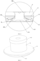
FIG. 1 is a schematic structural diagram of a pole provided in an embodiment of the present disclosure; -
FIG. 2 is a first exploded schematic diagram of the pole shown inFIG. 1 ; -
FIG. 3 is a second exploded schematic diagram of the pole shown inFIG. 1 ; -
FIG. 4 is a cross-sectional view of the pole shown inFIG. 1 ; -
FIG. 5 is a schematic structural diagram of a top cover structure provided in an embodiment of the present disclosure; -
FIG. 6 is an exploded schematic diagram of the top cover structure shown inFIG. 5 ; -
FIG. 7 is a partial schematic diagram of a top cover structure provided in an embodiment of the present disclosure; -
FIG. 8 is an enlarged schematic diagram of position A shown inFIG. 7 ; -
FIG. 9 is a schematic structural diagram of the pole shown inFIG. 6 ; -
FIG. 10 is a schematic structural diagram of an adapter provided in an embodiment of the present disclosure; -
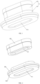
FIG. 11 is a schematic structural diagram of an insulating plate provided in an embodiment of the present disclosure; -
FIG. 12 is a schematic structural diagram of a battery provided in an embodiment of the present disclosure. -
- 1, cover assembly; 11, top cover plate; 12, insulating plate; 13, first groove; 14, second step groove; 15, second groove; 16, through hole;
- 2, terminal; 21, third step groove;
- 3, adapter; 31, pin piece; 311, convex bump; 3111, first step groove; 3112, plug-in portion; 312, fuse slot; 32, tab connection portion; 321, tab groove; 33, machine clamping portion;
- 4, pole; 41, first metal pillar; 411, cold heading forming groove; 412, protruding portion; 413, connecting step; 414, sealing flange portion; 42, second metal pillar; 421, recessed portion; 422, riveted flange portion; 43, cold heading joint surface;
- 5, insulation sealing ring;
- 6, upper insulation sheet;
- 7, protective film;
- 10, core package;
- 20, shell.
- In the description of the present disclosure, unless otherwise clearly specified and limited, the terms "mounted", "connected with", and "fixed" should be interpreted broadly, and may be, for example, fixed connections, detachable connections, or integral connections; it may be mechanical or electrical connections; it may also be direct connections or indirect connections via intermediate structures; it may also be internal communications of two elements or interaction relationships between two elements.
- In the present disclosure, unless otherwise clearly specified or limited, a first feature being "on" or "under" a second feature may include an embodiment in which the first feature is in direct contact with the second feature, or may also include an embodiment in which the first feature and the second feature are not in direct contact with each other, but are contacted via another feature formed therebetween. Furthermore, a first feature being "on", "above", or "on top of" a second feature may include an embodiment in which the first feature is right or obliquely above the second feature, or just means that the first feature is at a height higher than that of the second feature. A first feature being "below", "under", or "on bottom of" a second feature may include an embodiment in which the first feature is right or obliquely below the second feature, or just means that the first feature is at a height lower than that of the second feature.
- In the description of this embodiment, orientations or positional relationships indicated by terms such as "up", "down", "right", "left", are based on the orientations or positional relationships shown in the accompanying drawings, and are merely for the convenience of description and simplification of operation, rather than indicating or implying that the indicated device or element must have a specific orientation, be constructed and operated in a specific orientation, and therefore should not be understood as a limitation on the present disclosure. Furthermore, the terms "first" and "second" are only used for distinction in description, and have no special meanings.
- As shown in
FIGs. 1 to 4 , this embodiment provides apole 4, which includes afirst metal pillar 41 and asecond metal pillar 42 connected to each other. A first end of thefirst metal pillar 41 is provided with a coldheading forming groove 411, a second end of thefirst metal pillar 41 is provided with a protrudingportion 412. Thesecond metal pillar 42 is provided with a recessedportion 421. The protrudingportion 412 is embedded in the recessedportion 421 to form a cold headingjoint surface 43. The recessedportion 421 is recessed in a direction away from the coldheading forming groove 411. In one embodiment, one of thefirst metal pillar 41 and thesecond metal pillar 42 is a copper pillar, and the other is an aluminum pillar. In this embodiment, thefirst metal pillar 41 is a copper pillar, and thesecond metal pillar 42 is an aluminum pillar. In thepole 4, a mass proportion of copper is 5%-50%. - The
pole 4 in this embodiment can be made of a composite plate of thefirst metal pillar 41 and thesecond metal pillar 42 through a cold heading process. The first end of thefirst metal pillar 41 is repeatedly pressed using a cold heading mold. While the coldheading forming groove 411 is formed by pressing, the protrudingportion 412 is formed on the second end of thefirst metal pillar 41. The protrudingportion 412 is then punched into the recessedportion 421 on thesecond metal pillar 42, and the protrudingportion 412 is embedded in the recessedportion 421 to form the cold headingjoint surface 43 to connect thefirst metal pillar 41 and thesecond metal pillar 42, so as to manufacture thepole 4. The shape of the connection structure of thepole 4 is suitable for preparation by cold heading process, which has simple process and high material utilization rate, thereby reducing the manufacturing cost. The shape of the cold headingjoint surface 43 is not limited. In one embodiment, the cross-sectional shape of the cold headingjoint surface 43 is boss-shaped, circular, elliptical, triangular or arc-shaped. - Continuing to refer to
FIGs. 1 to 4 , in one embodiment, an outer periphery of thefirst metal pillar 41 is provided with a sealingflange portion 414. One side of the sealingflange portion 414 close to the coldheading forming groove 411 is provided with a connectingstep 413, and the coldheading forming groove 411 is provided on an end surface of the connectingstep 413. That is, the sealingflange portion 414 of thefirst metal pillar 41 forms the connectingstep 413 on one side close to the coldheading forming groove 411. The sealingflange portion 414 is provided to facilitate the sealing between thepole 4 and a cover assembly 1, and the connectingstep 413 is provided to facilitate the connection between thepole 4 and apin piece 31. In this embodiment, the sealingflange portion 414 and the connectingstep 413 are also formed by a cold heading process, so as to improve material utilization and reduce costs. - In one embodiment, along a direction from the cold
heading forming groove 411 to the protrudingportion 412, the thickness of the sealingflange portion 414 is 0.3-2.0 mm, and the thickness of the connectingstep 413 is 0.3-1.5 mm, so as to reduce the material consumption of thepole 4 while ensuring the connection strength. When the thickness of the sealingflange portion 414 is less than 0.3 mm, the thickness of the sealingflange portion 414 is too thin and the structural strength is poor. When the thickness of the sealingflange portion 414 is greater than 2 mm, the volume is too large, resulting in a significant increase in material consumption. When the thickness of the connectingstep 413 is less than 0.3 mm, the thickness of the connectingstep 413 is too thin and the structural strength is poor. When the thickness of the connectingstep 413 is greater than 2 mm, the volume is too large, resulting in a significant increase in material consumption. In one embodiment, the thickness of the sealingflange portion 414 is 0.3 mm, 0.4 mm, 0.5 mm, 0.6 mm, 0.7 mm, 0.8 mm, 0.9 mm, 1.0 mm, 1.1 mm, 1.2 mm, 1.3 mm, 1.4 mm, 1.5 mm, 1.6 mm, 1.7 mm, 1.8 mm, 1.9 mm or 2.0 mm; the thickness of the connectingstep 413 is 0.3 mm, 0.4 mm, 0.5 mm, 0.6 mm, 0.7 mm, 0.8 mm, 0.9 mm, 1.0 mm, 1.1 mm, 1.2 mm, 1.3 mm, 1.4 mm or 1.5 mm. In one embodiment, the cross-sections of the sealingflange portion 414 and the connectingstep 413 are circular, the diameter of the sealingflange portion 414 is 1.0-2.5 mm, and the diameter of the connectingstep 413 is 0.5-1.5 mm. In another embodiment, the sealingflange portion 414 and the connectingstep 413 are elliptical, a major axis length of the sealingflange portion 414 is 1.0-2.5 mm, and a major axis length of the connectingstep 413 is 0.5-1.5 mm. - In one embodiment, as shown in
FIGs. 3 andFIG. 4 , thesecond metal pillar 42 is provided with a rivetedflange portion 422. The rivetedflange portion 422 is located at an end of thesecond metal pillar 42 away from the recessedportion 421. The rivetedflange portion 422 is formed by a cold heading process, so as to improve material utilization. - As shown in
FIG. 5 , this embodiment provides a top cover structure, which includes a cover assembly 1, aterminal 2, anadapter 3 and the above-mentionedpole 4. - In one embodiment, as shown in
FIGs. 5 to 11 , theterminal 2 is arranged on a first side of the cover assembly 1. Theadapter 3 includes apin piece 31. Thepin piece 31 is located on a second side of the cover assembly 1. Thepin piece 31 is provided with a plug-inportion 3112. Thepole 4 penetrates the cover assembly 1, a first end of thepole 4 is connected to theterminal 2, and a second end is plugged into the plug-inportion 3112. The sealingflange portion 414 is located between thepin piece 31 and the cover assembly 1. A cross-sectional area of the sealingflange portion 414 is larger than a cross-sectional area of the plug-inportion 3112, and the sealingflange portion 414 is able to cover the plug-inportion 3112. In this embodiment, the cross-sectional shape of the sealingflange portion 414 is not limited, and may be circular, elliptical, triangular, diamond-shaped, rectangular, irregular, etc. - As shown in
FIGs. 7 to 9 , one end of thepole 4 located on one side of the sealingflange portion 414 and plugged into the plug-inportion 3112 is the connectingstep 413. The plug-inportion 3112 in this embodiment is a through hole. During the welding process of the connectingstep 413 on one side of thepin piece 31 away from the cover assembly 1, the cross-sectional area of the sealingflange portion 414 is larger than the cross-sectional area of the plug-inportion 3112, which can shield a gap between the connectingstep 413 and a hole wall of the plug-inportion 3112, thereby preventing the heat generated by the welding from being conducted to the vicinity of the cover assembly 1 through the gap, thereby improving the insulation and sealing effects between thepole 4 and the cover assembly 1. The cross-sectional shape of the plug-inportion 3112 is not limited, and the cross-sectional shape of the plug-inportion 3112 is adapted to the cross-sectional shape of the connectingstep 413. In the present embodiment, the plug-inportion 3112 is circular. - As shown in
FIG. 6 , in one embodiment, the cover assembly 1 includes atop cover plate 11 and an insulatingplate 12 arranged in a stack. Theterminal 2 is arranged on one side of thetop cover plate 11 away from the insulatingplate 12, thepin plate 31 is located on one side of the insulatingplate 12 away from thetop cover plate 11, and the sealingflange portion 414 is located between thepin plate 31 and the insulatingplate 12. In this embodiment, the insulatingplate 12 is a plastic plate, and is configured to isolate thepin piece 31 from thetop cover piece 11, so as to prevent thepin piece 31 from being electrically connected to thetop cover piece 11. The sealingflange portion 414 can be provided to protect the insulatingplate 12, thereby preventing the insulatingplate 12 from being deformed by heat when welding theconnection step 413, thereby preventing the insulating effect from being reduced. In order to insulate theterminal 2 and thetop cover sheet 11, the top cover structure further includes an upper insulating sheet 6, which is sandwiched between thetop cover sheet 11 and theterminal 2 to prevent thetop cover sheet 11 and the terminal 2 from being electrically connected. - As shown in
FIG. 6 , in one embodiment, the top cover structure further includes an insulatingsealing ring 5. The cover assembly 1 is provided with a throughhole 16. Thepole 4 penetrates the throughhole 16, the insulatingsealing ring 5 is sleeved on thepole 4, and the insulatingsealing ring 5 is arranged between the sealingflange portion 414 and the cover assembly 1. The insulatingsealing ring 5 is at least partially arranged between thepole 4 and an inner wall of the throughhole 16. The insulatingsealing ring 5 not only serves to insulate thepole 4 from the cover assembly 1, but also serves to seal the throughhole 16. The sealingflange portion 414 can be provided to protect the insulatingsealing ring 5, thereby preventing the insulatingsealing ring 5 from being deformed by heat when welding theconnection step 413, thereby preventing the insulating and sealing effects from being reduced. - As shown in
FIGs. 8 to 10 , in one embodiment, thepin piece 31 is provided with aconvex bump 311 protruding toward thepole 4. The plug-inportion 3112 is provided on theconvex bump 311, and the sealingflange portion 414 is located between theconvex bump 311 and the cover assembly 1. Theconvex bump 311 can make thepin piece 31 closer to the cover assembly 1, thereby reducing the size of thepole 4 in a direction from thepin piece 31 to theterminal 2, saving the material of thepole 4, and reducing the weight and cost. - In one embodiment, the cover assembly 1 is formed with a
first groove 13, and theconvex bump 311 is embedded in thefirst groove 13. Theconvex bump 311 is embedded in thefirst groove 13, so that the plug-inportion 3112 on theconvex bump 311 is closer to theterminal 2, which can further reduce the size of thepole 4 in the direction from thepin piece 31 to theterminal 2, saving materials for thepole 4 and reducing weight and cost. In this embodiment, thefirst groove 13 is formed on the insulatingplate 12. - Continuing to refer to
FIGs. 8-10 , in one embodiment, theconvex bump 311 is provided with afirst step groove 3111, thefirst step groove 3111 is located at a periphery of one end of the plug-inportion 3112 close to the cover assembly 1, and the sealingflange portion 414 is embedded in thefirst step groove 3111. The sealingflange portion 414 and thefirst step groove 3111 cooperate with each other, and the sealing performance between the sealingflange portion 414 and theconvex bump 311 is better, and the blocking effect of the sealingflange portion 414 on theconvex bump 311 is improved, thereby improving the sealing effect and insulation effect between thepole 4 and the cover assembly 1. - As shown in
FIG. 11 , in one embodiment, the cover assembly 1 is provided with asecond step groove 14. Thesecond step groove 14 is located in thefirst groove 13. A first end of the sealingflange portion 414 is embedded in thefirst step groove 3111, and a second end of the sealingflange portion 414 is embedded in thesecond step groove 14. In this embodiment, thesecond step groove 14 is formed on the insulatingplate 12. Thesecond step groove 14 not only increases the contact area between the sealingflange portion 414 and the cover assembly 1, and improves the sealing between the sealingflange portion 414 and the insulatingplate 12, but also can further reduce the design size of thepole 4, save materials, reduce weight, and reduce costs. - As shown in
FIG. 11 , in one embodiment, the cover assembly 1 is provided with asecond groove 15, thefirst groove 13 is located in thesecond groove 15, and thepin piece 31 is embedded in thesecond groove 15. In this embodiment, thesecond groove 15 is formed on the insulatingplate 12. Thepin piece 31 is entirely embedded in thesecond groove 15, which facilitates the relative positioning between thepin piece 31 and the insulatingplate 12, at the same time, the design size of thepole 4 can be further reduced, the weight can be reduced, and the cost can be reduced. - As shown in
FIG. 9 , thepole 4 is riveted to theterminal 2 via the rivetedflange portion 422. In one embodiment, as shown inFIG. 6 , theterminal 2 is provided with athird step groove 21, and the rivetedflange portion 422 is embedded in thethird step groove 21. The cross-sectional area of the middle portion of thepole 4 is smaller than the cross-sectional area of the rivetedflange portion 422. One side of theterminal 2 away from thepin piece 31 is riveted to the rivetedflange portion 422 and theterminal 2. - In this embodiment, the
pole 4 serving as the negative electrode on the cover assembly 1 is made of copper-aluminum composite plate by cold heading process, the sealingflange portion 414 and the rivetedflange portion 422 are formed by cold heading process, and the material utilization rate of the copper-aluminum composite plate can reach 100%. - Along a direction from the
pin piece 31 to theterminal 2, the thickness of the sealingflange portion 414 is 0.3-2.0 mm, and the thickness of the connectingstep 413 is 0.3-1.5 mm. In this embodiment, the diameter of the sealingflange portion 414 is 1.0-2.5 mm, and the diameter of the connectingstep 413 is 0.5-1.5 mm. By designing the dimensions of the sealingflange portion 414 and the connectingstep 413, the conduction of heat to an inner layer of the top cover structure during the welding process can be reduced. - As shown in
FIG. 10 , in one embodiment, theadapter 3 further includes atab connection portion 32 connected to thepin piece 31, and thetab connection portion 32 is connected to a tab of a core package. In one embodiment, thetab connection portion 32 is provided with atab groove 321, and thetab groove 321 is configured to accommodate and limit the tab. In this embodiment, one end of thepin piece 31 close to thetab connection portion 32 is provided with afuse slot 312. Thefuse slot 312 can reduce the cross-sectional area of thepin piece 31. When the current on thepin piece 31 surges, thepin piece 31 at thefuse slot 312 will be fused to achieve protection. - In one embodiment, still referring to
FIG. 10 , thetab connecting portion 32 is further provided with amachine clamping portion 33 to facilitate an external jig to clamp theadapter 3 and implement production operations. In one embodiment, one side of theadapter 3 facing away from the cover assembly 1 is attached with aprotective film 7. Theprotective film 7 can insulate and isolate the core package from theadapter 3, and can also prevent theadapter 3 from being scratched during the production process, thereby affecting the performance of theadapter 3. - This embodiment further provides a battery, as shown in
FIG. 12 , the battery includes the above-mentioned top cover structure, acore package 10 and ashell 20. Thecore package 10 is provided in theshell 20, and the top cover structure is sealed on theshell 20. By using the above-mentioned top cover structure, the cost of the battery can be reduced and the safety of the battery can be improved. - This embodiment further provides a battery module, including the above-mentioned battery. By using the above-mentioned battery, the cost of the battery module can be reduced and the safety of the battery module can be improved.
- This embodiment further provides a battery pack, including the above-mentioned battery module. By using the above-mentioned battery module, the cost of the battery pack can be reduced and the safety of the battery pack can be improved.
Claims (16)
- A pole comprises a first metal pillar (41) and a second metal pillar (42) connected to each other; wherein a first end of the first metal pillar (41) is provided with a cold heading forming groove (411), and a second end of the first metal pillar (41) is provided with a protruding portion (412); the second metal pillar (42) is provided with a recessed portion (421); the protruding portion (412) is embedded in the recessed portion (421) to form a cold heading joint surface (43); the recessed portion (421) is recessed in a direction away from the cold heading forming groove (411).
- The pole according to claim 1, wherein an outer periphery of the first metal pillar (41) is provided with a sealing flange portion (414); wherein one side of the sealing flange portion (414) close to the cold heading forming groove (411) is provided with a connecting step (413), and the cold heading forming groove (411) is provided on an end face of the connecting step (413).
- The pole according to claim 2, wherein, along a direction from the cold heading forming groove (411) to the protruding portion (412), the thickness of the sealing flange portion (414) is 0.3-2.0 mm, and the thickness of the connecting step (413) is 0.3-1.5 mm.
- The pole according to claim 1, wherein a cross-sectional shape of the cold heading joint surface (43) is boss-shaped, circular, elliptical, triangular or arc-shaped.
- The pole according to claim 1, wherein one of the first metal pillar (41) and the second metal pillar (42) is a copper pillar, and the other is an aluminum pillar.
- A top cover structure, comprising the pole (4) as claimed in any one of claims 1 to 5.
- A top cover structure, comprising:the pole (4) as claimed in any one of claims 2 to 3;a cover assembly (1); anda pin piece (31) provided with a plug-in portion (3112);wherein the pole (4) penetrates the cover assembly (1), with the connecting step (413) being plugged into the plug-in portion (3112), and the sealing flange portion (414) being located between the pin piece (31) and the cover assembly (1); wherein a cross-sectional area of the sealing flange portion (414) is larger than a cross-sectional area of the plug-in portion (3112), and the sealing flange portion (414) is able to cover the plug-in portion (3112).
- The top cover structure according to claim 7, wherein the pin piece (31) is provided with a convex bump (311) protruding toward the pole (4); the plug-in portion (3112) is provided on the convex bump (311), and the sealing flange portion (414) is located between the convex bump (311) and the cover assembly (1).
- The top cover structure according to claim 8, wherein the convex bump (311) is provided with a first step groove (3111) located at a periphery of one end of the plug-in portion (3112) close to the pole (4); wherein the sealing flange portion (414) is embedded in the first step groove (3111).
- The top cover structure according to claim 8, wherein the cover assembly (1) is provided with a first groove (13); wherein the convex bump (311) is embedded in the first groove (13).
- The top cover structure according to claim 10, wherein the cover assembly (1) is provided with a second step groove (14) located in the first groove (13); wherein the sealing flange portion (414) is embedded in the second step groove (14).
- The top cover structure according to claim 10, wherein the cover assembly (1) is provided with a second groove (15); wherein the first groove (13) is located in the second groove (15), and the pin piece (31) is embedded in the second groove.
- The top cover structure according to claim 7, further comprising an insulating sealing ring (5); wherein the cover assembly (1) is provided with a through hole (16); the pole (4) penetrates the through hole (16), the insulating sealing ring (5) is sleeved on the pole (4), and the insulating sealing ring (5) is arranged between the sealing flange portion (414) and the cover assembly (1).
- A battery, comprising the top cover structure as claimed in any one of claims 6 to 13, a core package (10) and a shell (20), wherein the core package (10) is provided in the shell (20), and the top cover structure is sealed on the shell (20).
- A battery module comprising the battery as claimed in claim 14.
- A battery pack comprising the battery module as claimed in claim 15.
Applications Claiming Priority (2)
| Application Number | Priority Date | Filing Date | Title |
|---|---|---|---|
| CN202321090677.XU CN220291026U (en) | 2023-05-09 | 2023-05-09 | Poles, top cover structures, batteries, battery modules and battery packs |
| PCT/CN2023/101622 WO2024055666A1 (en) | 2023-05-09 | 2023-06-21 | Post terminal, top cover structure, battery, battery module and battery pack |
Publications (2)
| Publication Number | Publication Date |
|---|---|
| EP4571996A1 true EP4571996A1 (en) | 2025-06-18 |
| EP4571996A4 EP4571996A4 (en) | 2026-01-21 |
Family
ID=89325549
Family Applications (1)
| Application Number | Title | Priority Date | Filing Date |
|---|---|---|---|
| EP23864405.8A Pending EP4571996A4 (en) | 2023-05-09 | 2023-06-21 | Terminal clamp, upper cover structure, battery, battery module and battery pack |
Country Status (5)
| Country | Link |
|---|---|
| US (1) | US20250158180A1 (en) |
| EP (1) | EP4571996A4 (en) |
| CN (1) | CN220291026U (en) |
| MX (1) | MX2025007026A (en) |
| WO (1) | WO2024055666A1 (en) |
Families Citing this family (4)
| Publication number | Priority date | Publication date | Assignee | Title |
|---|---|---|---|---|
| US20240413441A1 (en) * | 2023-06-09 | 2024-12-12 | Huizhou Eve Power Co., Ltd | Pole post, top cap assembly, and cell |
| CN220710580U (en) * | 2023-07-20 | 2024-04-02 | 湖北亿纬动力有限公司 | A pole, top cover structure, battery core, battery module and battery pack |
| CN118040253B (en) * | 2024-04-12 | 2024-07-26 | 广州众山精密科技有限公司 | A method for preparing copper-aluminum composite pole plate |
| CN119651010A (en) * | 2025-02-19 | 2025-03-18 | 蜂巢能源科技股份有限公司 | Battery cover structure and battery |
Family Cites Families (5)
| Publication number | Priority date | Publication date | Assignee | Title |
|---|---|---|---|---|
| US6844110B2 (en) * | 2000-05-24 | 2005-01-18 | Ngk Insulators, Ltd. | Lithium secondary cell and assembly thereof |
| KR20150136412A (en) * | 2014-05-27 | 2015-12-07 | 삼성에스디아이 주식회사 | Rechargeable battery having plate terminal |
| CN204946994U (en) * | 2015-08-19 | 2016-01-06 | 宁波市华宝塑胶模具股份有限公司 | The combination electrode of automobile batteries |
| CN213989132U (en) * | 2020-12-11 | 2021-08-17 | 厦门海辰新能源科技有限公司 | Light-duty utmost point post subassembly, top cap structure and power battery |
| CN218005058U (en) * | 2022-07-19 | 2022-12-09 | 湖北亿纬动力有限公司 | Top cover assembly and battery |
-
2023
- 2023-05-09 CN CN202321090677.XU patent/CN220291026U/en active Active
- 2023-06-21 WO PCT/CN2023/101622 patent/WO2024055666A1/en not_active Ceased
- 2023-06-21 EP EP23864405.8A patent/EP4571996A4/en active Pending
-
2025
- 2025-01-14 US US19/021,062 patent/US20250158180A1/en active Pending
- 2025-06-16 MX MX2025007026A patent/MX2025007026A/en unknown
Also Published As
| Publication number | Publication date |
|---|---|
| MX2025007026A (en) | 2025-07-01 |
| EP4571996A4 (en) | 2026-01-21 |
| US20250158180A1 (en) | 2025-05-15 |
| CN220291026U (en) | 2024-01-02 |
| WO2024055666A1 (en) | 2024-03-21 |
Similar Documents
| Publication | Publication Date | Title |
|---|---|---|
| EP4571996A1 (en) | Post terminal, top cover structure, battery, battery module and battery pack | |
| US20220238973A1 (en) | Battery and electric apparatus with such battery | |
| WO2023151320A1 (en) | Battery cover plate assembly, cylindrical battery, and battery pack | |
| CN210743993U (en) | Top cover assembly, secondary battery, battery module, and device | |
| CN217009372U (en) | Battery with a battery cell | |
| EP4568004A1 (en) | Power battery cover and power battery | |
| CN217009287U (en) | Cylindrical lithium ion battery | |
| CN220358209U (en) | Battery cell | |
| WO2025237325A1 (en) | Pole, cover plate and battery | |
| CN214043796U (en) | Power battery device | |
| CN210200769U (en) | Power battery top cover structure and power battery | |
| US20250158178A1 (en) | Battery, battery module, and electric device | |
| CN214625188U (en) | Power battery cover plate assembly and power battery | |
| EP4395019A1 (en) | Cylindrical battery and electronic device | |
| CN223092979U (en) | Battery Cells and Battery Packs | |
| CN213304244U (en) | Battery shell assembly and battery | |
| CN211629148U (en) | Cover plate structure of lithium battery | |
| CN221708822U (en) | Battery cover plate and lithium ion battery | |
| CN221407474U (en) | Battery top cover and power battery | |
| CN218101629U (en) | Current collectors, batteries, battery packs and electrical equipment | |
| CN218648042U (en) | Power battery structure | |
| CN223273390U (en) | Positive electrode terminal assembly for battery cell top cover and battery cell top cover assembly | |
| CN223785219U (en) | A battery top cover structure | |
| CN223245857U (en) | Top cap module and battery | |
| CN222927625U (en) | Negative electrode terminal assembly for battery cell top cap and battery cell top cap assembly |
Legal Events
| Date | Code | Title | Description |
|---|---|---|---|
| STAA | Information on the status of an ep patent application or granted ep patent |
Free format text: STATUS: THE INTERNATIONAL PUBLICATION HAS BEEN MADE |
|
| PUAI | Public reference made under article 153(3) epc to a published international application that has entered the european phase |
Free format text: ORIGINAL CODE: 0009012 |
|
| STAA | Information on the status of an ep patent application or granted ep patent |
Free format text: STATUS: REQUEST FOR EXAMINATION WAS MADE |
|
| 17P | Request for examination filed |
Effective date: 20250310 |
|
| AK | Designated contracting states |
Kind code of ref document: A1 Designated state(s): AL AT BE BG CH CY CZ DE DK EE ES FI FR GB GR HR HU IE IS IT LI LT LU LV MC ME MK MT NL NO PL PT RO RS SE SI SK SM TR |
|
| A4 | Supplementary search report drawn up and despatched |
Effective date: 20251219 |
|
| RIC1 | Information provided on ipc code assigned before grant |
Ipc: H01M 50/553 20210101AFI20251215BHEP Ipc: H01M 50/564 20210101ALI20251215BHEP Ipc: H01M 50/15 20210101ALI20251215BHEP Ipc: H01M 50/176 20210101ALI20251215BHEP Ipc: H01M 50/562 20210101ALI20251215BHEP |