EP4571992A1 - Jelly roll center pin and battery - Google Patents
Jelly roll center pin and battery Download PDFInfo
- Publication number
- EP4571992A1 EP4571992A1 EP24861299.6A EP24861299A EP4571992A1 EP 4571992 A1 EP4571992 A1 EP 4571992A1 EP 24861299 A EP24861299 A EP 24861299A EP 4571992 A1 EP4571992 A1 EP 4571992A1
- Authority
- EP
- European Patent Office
- Prior art keywords
- support
- winding core
- wall
- central pin
- support rod
- Prior art date
- Legal status (The legal status is an assumption and is not a legal conclusion. Google has not performed a legal analysis and makes no representation as to the accuracy of the status listed.)
- Pending
Links
Images

Classifications
-
- H—ELECTRICITY
- H01—ELECTRIC ELEMENTS
- H01M—PROCESSES OR MEANS, e.g. BATTERIES, FOR THE DIRECT CONVERSION OF CHEMICAL ENERGY INTO ELECTRICAL ENERGY
- H01M10/00—Secondary cells; Manufacture thereof
- H01M10/05—Accumulators with non-aqueous electrolyte
- H01M10/058—Construction or manufacture
- H01M10/0587—Construction or manufacture of accumulators having only wound construction elements, i.e. wound positive electrodes, wound negative electrodes and wound separators
-
- H—ELECTRICITY
- H01—ELECTRIC ELEMENTS
- H01M—PROCESSES OR MEANS, e.g. BATTERIES, FOR THE DIRECT CONVERSION OF CHEMICAL ENERGY INTO ELECTRICAL ENERGY
- H01M10/00—Secondary cells; Manufacture thereof
- H01M10/04—Construction or manufacture in general
- H01M10/0431—Cells with wound or folded electrodes
-
- Y—GENERAL TAGGING OF NEW TECHNOLOGICAL DEVELOPMENTS; GENERAL TAGGING OF CROSS-SECTIONAL TECHNOLOGIES SPANNING OVER SEVERAL SECTIONS OF THE IPC; TECHNICAL SUBJECTS COVERED BY FORMER USPC CROSS-REFERENCE ART COLLECTIONS [XRACs] AND DIGESTS
- Y02—TECHNOLOGIES OR APPLICATIONS FOR MITIGATION OR ADAPTATION AGAINST CLIMATE CHANGE
- Y02E—REDUCTION OF GREENHOUSE GAS [GHG] EMISSIONS, RELATED TO ENERGY GENERATION, TRANSMISSION OR DISTRIBUTION
- Y02E60/00—Enabling technologies; Technologies with a potential or indirect contribution to GHG emissions mitigation
- Y02E60/10—Energy storage using batteries
-
- Y—GENERAL TAGGING OF NEW TECHNOLOGICAL DEVELOPMENTS; GENERAL TAGGING OF CROSS-SECTIONAL TECHNOLOGIES SPANNING OVER SEVERAL SECTIONS OF THE IPC; TECHNICAL SUBJECTS COVERED BY FORMER USPC CROSS-REFERENCE ART COLLECTIONS [XRACs] AND DIGESTS
- Y02—TECHNOLOGIES OR APPLICATIONS FOR MITIGATION OR ADAPTATION AGAINST CLIMATE CHANGE
- Y02P—CLIMATE CHANGE MITIGATION TECHNOLOGIES IN THE PRODUCTION OR PROCESSING OF GOODS
- Y02P70/00—Climate change mitigation technologies in the production process for final industrial or consumer products
- Y02P70/50—Manufacturing or production processes characterised by the final manufactured product
Definitions
- the present disclosure relates to the field of battery manufacturing, and in particular to a winding core central pin and a battery.
- a cylindrical battery usually includes a housing and a winding core arranged inside the housing.
- the winding core is formed by winding a positive electrode, a separator, and a negative electrode.
- an interior of the formed winding core is hollow.
- the winding core may be expanded, such that the interior of the winding core may be collapsed and deformed. Therefore, the winding core may be fractured, affecting a service life of the battery.
- a cylindrical central pin may be arranged in the hollow interior of the winding core to support the winding core to prevent the winding core from collapsing and deforming inwardly.
- the above technical solution has following defects: the cylindrical central pin is attached to an inner wall of the hollow interior of the winding core, and in this way, flowing of an electrolyte is blocked, affecting absorption of the electrolyte by the winding core.
- a winding core central pin in a first aspect, includes a support rod and a plurality of support ribs.
- the support rod is cylindrical; the plurality of support ribs are arranged along a circumferential direction of an outer wall of the support rod and have an equal inclination angle with respect to the outer wall of the support rod; the plurality of support ribs are configured to abut against an inner wall of a center hole of a winding core; an avoidance space is defined between every two adjacent support ribs of the plurality of support ribs to allow an electrolyte to flow through the avoidance space.
- a battery in a second aspect, includes a housing, a winding core arranged inside the housing, and the winding core central pin in the first aspect.
- the winding core central pin is inserted in the center hole of the winding core.
- all support ribs uniformly are arranged along a circumferential direction and abut against an inner wall of the center hole of the winding core.
- Two adjacent support ribs and the inner wall of the center hole of the winding core cooperatively form a sector-shaped structure, which is similar to a triangle, such that the winding core is stably supported.
- an avoiding space formed between the two adjacent support ribs allows the electrolyte to flow through, obstruction of the flowing of electrolyte is reduced, enabling the winding core to be soaked in and to absorb the electrolyte.
- a contact area between the support ribs and the inner wall of the center hole of the winding core is smaller, such that a contact area between the inner wall of the center hole of the winding core and the electrolyte is increased. In this way, an influence, caused by the central pin, on the absorption of electrolyte by the winding core is reduced, such that performance of the winding core is ensured.
- a winding core central pin is provided and includes a support rod 1 and a plurality of support ribs 2.
- the support rod 1 is cylindrical.
- the plurality of support ribs 2 are arranged along a circumferential direction of an outer wall of the support rod 1 and have an equal inclination angle with respect to the outer wall of the support rod 1.
- the plurality of support ribs 2 are configured to abut against an inner wall of a center hole 101 of the winding core 100 to support the winding core 100 to prevent the winding core 100 from collapsing and deformation inwardly.
- An avoidance space 3 is defined between every two adjacent support ribs 2 of the plurality of support ribs 2, allowing the electrolyte to flow through the avoidance space 3.
- all the plurality of support ribs 2 are uniformly arranged along the circumferential direction and abut against the inner wall of the center hole 101 of the winding core 100.
- the every two adjacent support ribs 2 and the inner wall of the center hole 101 of the winding core 100 cooperatively form a substantially triangular-sector structure, such that the winding core 100 is stably supported.
- the avoidance space 3 defined between the every two adjacent support ribs 2 allows the electrolyte flow through. Obstruction against the flowing of the electrolyte is reduced, facilitating the winding core 100 to be soaked in and to absorb the electrolyte.
- a contact area between the plurality of support ribs 2 and the inner wall of the center hole 101 of the winding core 100 is smaller, such that a contact area between the inner wall of the center hole 101 of the winding core 100 and the electrolyte is increased. In this way, the influence, caused by the winding core central pin, on the absorption of the electrolyte by the winding core 100 is reduced optimally, ensuring performance of the winding core 100.
- the number of the plurality of support ribs 2 may be two or more, and the number of the plurality of support ribs 2 is not specifically limited herein.
- the outer wall of the support rod 1 and/or the plurality of support ribs 2 define a plurality of through holes 9 extending through the outer wall of the support rod 1 and/or the plurality of support ribs 2.
- the plurality of through holes 9 are defined in and extend through both the outer wall of the support rod 1 and the plurality of support ribs 2.
- the plurality of through holes 9 are communicated with all avoidance spaces 3 to allow the electrolyte to flow through all of the avoidance spaces 3 to facilitate the winding core 100 to be soaked in and to absorb the electrolyte.
- a diameter of each of the plurality of through holes 9 is in a range of 1mm to 3mm.
- the diameter of the through hole 9 may be 1mm, 1.5mm, 2mm, 2.5mm, 3mm and so on. If the diameter of the through hole 9 is excessively large, strength of the winding core central pin is reduced. The excessively large diameter of the through hole 9 may affect a flowing efficiency of the electrolyte. The above configuration may improve the flowing efficiency of the electrolyte as much as possible without affecting the strength of the winding core central pin.
- each of the outer wall of the support rod 1 and the outer wall of each support rib 2 defines an air guiding slot 8.
- the air guiding slot 8 extends along a length direction of the central pin. That is, a length direction of the support rod 1 is the same as a length direction of each support rib 2.
- the air guiding slot 8 on the support rod 1 extends along the length direction of the support rod 1 and extends through both ends of the support rod 1 in the length direction.
- the air guiding slot 8 on the support rib 2 extends along the length direction of the support rib 2 and extends through both ends of the support rod 1 along the length direction.
- the air guiding slot 8 quickly directs the gas to an exterior of the winding core 100 to improve an efficiency of gas and pressure releasing.
- all of the support ribs 2 are arranged on the support rod 1 and are extendable and retractable along a radial direction of the support rod 1, such that a supportive outer diameter of the winding core central pin is adjustable, and the winding core central pin may be applied to various center holes 101 of winding cores 100 having various diameters.
- a mounting cavity 11 is defined inside the support rod 1.
- the winding core central pin further includes a contraction structure 4.
- the contraction structure 4 is arranged inside the mounting cavity 11.
- the contraction structure 4 includes a cylindrical connecting rod 41.
- a center axis of the connecting rod 41 coincides with a center axis of the support rod 1.
- a plurality of elastic members 42 are arranged along a circumferential direction of the connecting rod 41, and the plurality of elastic members 42 have an equal inclination angle with respect to the circumferential direction of the connecting rod 41.
- the outer wall of the support rod 1 defines a plurality of openings 12 at positions corresponding to the plurality of support ribs 2.
- the number of the plurality of elastic members 42, the number of the plurality of openings 12, and the number of the plurality of support ribs 2 are the same to each other.
- An end of each of the plurality of support ribs 2 is arranged inside the support rod 1 and is connected to a respective one of the plurality of elastic members 42, and the other end of each of the plurality of support ribs 2 extends to an exterior of the support rod 1 through a respective one of the plurality of openings 12.
- the plurality of elastic members 42 drive the plurality of support ribs 2 to have a tendency to move to abut against the inner wall of the center hole 101 of the winding core 100, such that the support ribs 2 are extendable and retractable to be arranged on the support rod 1.
- the support ribs 2 When the winding core central pin needs to be inserted into the center hole 101 of the winding core 100, the support ribs 2 are compressed to move towards the interior of the mounting cavity 11 to reduce the supportive outer diameter of the winding core central pin, enabling the winding core central pin to be inserted into the center hole 101. After inserting the winding core central pin into the center hole 101, the support ribs 2, under actions of the elastic members 42, automatically move towards the exterior of the support rod 1 to abut against the inner wall of the center hole 101 of the winding core 100. In this way, the winding core central pin is mounted.
- a limiting member 5 is arranged in the mounting cavity 11.
- the limiting member 5 includes a plurality of support portions 51 arranged along the circumferential direction of the support rod 1, and the plurality of support portions 51 have an equal inclination angle with respect to the circumferential direction.
- the number of the plurality of support portions 51 is the same as the number of the plurality of openings 12.
- Each of the plurality of support portions 51 defines a limiting through slot 511 communicating with the respective one of the plurality of openings 12.
- a length of each limiting through slot 511 extends along a moving direction of the respective support rib 2.
- the support rib 2 is slidably arranged inside the limiting through slot 511.
- At least portion of the respective elastic member 42 is arranged inside the limiting through slot 511 and is connected to an end of the support rib 2.
- the elastic member 42 drives the support rib 2 to slide in the limiting through slot, such that the other end of the support rib 2 to slide out of the limiting through hole 9 and extend through the opening 12 to the exterior of the support rod 1.
- the elastic member 5 guides the moving direction of the support rib 2 to prevent the support rib 2 from being shifted to be stuck inside the support rod 1, ensuring that the support rib 2 can be extended to the exterior of the support rod 1.
- each support portion 51 has a first end and a second end opposite to the first end.
- the length direction of the limiting through slot 511 is the same as a direction extending from the first end to the second end.
- the limiting through slot 511 extends through the first end and the second end.
- First ends of all of the plurality of support portions 51 are connected to each other, and second ends of all of the plurality of support portions 51 are connected to an inner wall of the support rod 1 and the plurality of openings 12 respectively.
- the first ends of all the plurality of support portions 51 are connected to each other to cooperatively form an integral and one-piece limiting member 5, enabling the plurality of support portions 51 to interact with each other to support the inner wall of the support rod 1 to improve the strength of the support rod 1.
- limiting through slots 511 of all the plurality of support portions 51 are communicated with each other in order to form a mounting space inside the limiting member 5.
- the contraction structure 4 is arranged inside the mounting space and is connected to the support ribs 2.
- the center axis of a connection position of the first ends of all the plurality of support portions 51 is the center axis of the limiting member 5.
- the connecting rod 41 is disposed at the center axis of the limiting member 5.
- the center axis of the connecting rod 41 coincides with the center axis of the limiting member 5.
- All the plurality of elastic members 42 are arranged along the circumferential direction of the connecting rod 41 and have an equal inclination angle with respect to the circumferential direction. An end of each elastic member 42 away from the connecting rod 41 extends into the respective limiting through slot 511 and is connected to the respective support rib 2.
- a slot wall of the limiting through slot 511 defines a first limiting portion 6 at a position adjacent to the second end.
- the support rib 2 is arranged with a second limiting portion 7 that is snap-fitted with the first limiting portion 6.
- the first limiting portion 6 is a first protrusion.
- the first protrusion protrudes toward a center of the limiting through slot 511.
- the second limiting portion 7 is a second protrusion.
- An outer wall of the end of the support rib 2 connected to the elastic member 42 is arranged with the second protrusion.
- the limiting member 5 separates the interior of the support rod 1 into a plurality of circulation spaces.
- the limiting member 5 defines a flow guiding hole extending through the limiting member 5. All the plurality of circulation spaces are communicated, through the flow guiding hole, to each other.
- the avoidance spaces 3 are also communicated, through the plurality of through holes 9, to each other, enabling the electrolyte to circulate in the interior and the exterior of the winding core central pin to soak the winding core 100.
- Each of the inner wall and the outer wall of the support rod 1 defines the air guiding slot 8.
- An outer wall of the limiting member 5 also defines the air guiding slot 8. In this way, an air guiding effect is improved.
- a battery is further provided and includes a housing, the cylindrical winding core 100 arranged inside the housing, and the winding core central pin as described in any of the above embodiments.
- the winding core central pin is inserted in the center hole 101 of the winding core 100.
- the winding core central pin is arranged to prevent the winding core 100 from collapsing and deformation inwardly and to minimize the influence on the absorption of the electrolyte by the winding core 100. The performance and the service life of the battery are improved.
Landscapes
- Engineering & Computer Science (AREA)
- Manufacturing & Machinery (AREA)
- Chemical & Material Sciences (AREA)
- Chemical Kinetics & Catalysis (AREA)
- Electrochemistry (AREA)
- General Chemical & Material Sciences (AREA)
- Secondary Cells (AREA)
Abstract
Description
- The present application claims the priority of the
Chinese patent application No. 202322561513.7, filed on September 20, 2023 - The present disclosure relates to the field of battery manufacturing, and in particular to a winding core central pin and a battery.
- A cylindrical battery usually includes a housing and a winding core arranged inside the housing. The winding core is formed by winding a positive electrode, a separator, and a negative electrode. However, an interior of the formed winding core is hollow. When the battery is being used cyclically, due to the hollow interior, the winding core may be expanded, such that the interior of the winding core may be collapsed and deformed. Therefore, the winding core may be fractured, affecting a service life of the battery.
- In the art, a cylindrical central pin may be arranged in the hollow interior of the winding core to support the winding core to prevent the winding core from collapsing and deforming inwardly. The above technical solution has following defects: the cylindrical central pin is attached to an inner wall of the hollow interior of the winding core, and in this way, flowing of an electrolyte is blocked, affecting absorption of the electrolyte by the winding core.
- In a first aspect, a winding core central pin is provided and includes a support rod and a plurality of support ribs. The support rod is cylindrical; the plurality of support ribs are arranged along a circumferential direction of an outer wall of the support rod and have an equal inclination angle with respect to the outer wall of the support rod; the plurality of support ribs are configured to abut against an inner wall of a center hole of a winding core; an avoidance space is defined between every two adjacent support ribs of the plurality of support ribs to allow an electrolyte to flow through the avoidance space.
- In a second aspect, a battery is provided and includes a housing, a winding core arranged inside the housing, and the winding core central pin in the first aspect. The winding core central pin is inserted in the center hole of the winding core.
- According to the present disclosure, when the central pin is inserted into a center hole of the winding core, all support ribs uniformly are arranged along a circumferential direction and abut against an inner wall of the center hole of the winding core. Two adjacent support ribs and the inner wall of the center hole of the winding core cooperatively form a sector-shaped structure, which is similar to a triangle, such that the winding core is stably supported. In addition, an avoiding space formed between the two adjacent support ribs allows the electrolyte to flow through, obstruction of the flowing of electrolyte is reduced, enabling the winding core to be soaked in and to absorb the electrolyte. A contact area between the support ribs and the inner wall of the center hole of the winding core is smaller, such that a contact area between the inner wall of the center hole of the winding core and the electrolyte is increased. In this way, an influence, caused by the central pin, on the absorption of electrolyte by the winding core is reduced, such that performance of the winding core is ensured.
-
-
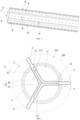
FIG. 1 is a perspective view of a winding core central pin according to some embodiments. -
FIG. 2 is a cross-sectional view of the winding core central pin providing support according to some embodiments. -
FIG. 3 is a cross-sectional view of the winding core central pin being contracted according to some embodiments. -
FIG. 4 shows an enlarged view of a portion A shown inFIG. 2 . - Reference numerals in the drawings:
- 100, winding core; 101, center hole;
- 1, support rod; 11, mounting cavity; 12, opening; 2, support rib; 3, avoiding space; 4, contraction structure;
- 41, connecting rod; 42, elastic member; 5, limiting member; 51, support portion; 511, limiting through slot; 6, first limiting portion; 7, second limiting portion; 8, air guiding slot; 9, through hole.
- As shown in
FIGS. 1 to 3 , a winding core central pin is provided and includes asupport rod 1 and a plurality ofsupport ribs 2. Thesupport rod 1 is cylindrical. The plurality ofsupport ribs 2 are arranged along a circumferential direction of an outer wall of thesupport rod 1 and have an equal inclination angle with respect to the outer wall of thesupport rod 1. The plurality ofsupport ribs 2 are configured to abut against an inner wall of acenter hole 101 of the windingcore 100 to support the windingcore 100 to prevent the windingcore 100 from collapsing and deformation inwardly. Anavoidance space 3 is defined between every twoadjacent support ribs 2 of the plurality ofsupport ribs 2, allowing the electrolyte to flow through theavoidance space 3. - When the winding core central pin is inserted into the
center hole 101 of the windingcore 100, all the plurality ofsupport ribs 2 are uniformly arranged along the circumferential direction and abut against the inner wall of thecenter hole 101 of thewinding core 100. The every twoadjacent support ribs 2 and the inner wall of thecenter hole 101 of the windingcore 100 cooperatively form a substantially triangular-sector structure, such that the windingcore 100 is stably supported. In addition, theavoidance space 3 defined between the every twoadjacent support ribs 2 allows the electrolyte flow through. Obstruction against the flowing of the electrolyte is reduced, facilitating the windingcore 100 to be soaked in and to absorb the electrolyte. Furthermore, when the battery is operating abnormally and needs to release a pressure, gas can be released from theavoidance space 3. A contact area between the plurality ofsupport ribs 2 and the inner wall of thecenter hole 101 of thewinding core 100 is smaller, such that a contact area between the inner wall of thecenter hole 101 of thewinding core 100 and the electrolyte is increased. In this way, the influence, caused by the winding core central pin, on the absorption of the electrolyte by the windingcore 100 is reduced optimally, ensuring performance of the windingcore 100. - It should be noted that the number of the plurality of
support ribs 2 may be two or more, and the number of the plurality ofsupport ribs 2 is not specifically limited herein. - Further, as shown in
FIG. 1 , the outer wall of thesupport rod 1 and/or the plurality ofsupport ribs 2 define a plurality of throughholes 9 extending through the outer wall of thesupport rod 1 and/or the plurality ofsupport ribs 2. In the present embodiment, the plurality of throughholes 9 are defined in and extend through both the outer wall of thesupport rod 1 and the plurality ofsupport ribs 2. The plurality of throughholes 9 are communicated with allavoidance spaces 3 to allow the electrolyte to flow through all of theavoidance spaces 3 to facilitate the windingcore 100 to be soaked in and to absorb the electrolyte. - In some embodiments, a diameter of each of the plurality of through
holes 9 is in a range of 1mm to 3mm. For example, the diameter of thethrough hole 9 may be 1mm, 1.5mm, 2mm, 2.5mm, 3mm and so on. If the diameter of the throughhole 9 is excessively large, strength of the winding core central pin is reduced. The excessively large diameter of thethrough hole 9 may affect a flowing efficiency of the electrolyte. The above configuration may improve the flowing efficiency of the electrolyte as much as possible without affecting the strength of the winding core central pin. - In some embodiments, as shown in
FIG. 1 , each of the outer wall of thesupport rod 1 and the outer wall of eachsupport rib 2 defines an air guidingslot 8. The air guidingslot 8 extends along a length direction of the central pin. That is, a length direction of thesupport rod 1 is the same as a length direction of eachsupport rib 2. The air guidingslot 8 on thesupport rod 1 extends along the length direction of thesupport rod 1 and extends through both ends of thesupport rod 1 in the length direction. The air guidingslot 8 on thesupport rib 2 extends along the length direction of thesupport rib 2 and extends through both ends of thesupport rod 1 along the length direction. When the battery needs to release gas to release the pressure, the air guidingslot 8 quickly directs the gas to an exterior of the windingcore 100 to improve an efficiency of gas and pressure releasing. - In some embodiments, all of the
support ribs 2 are arranged on thesupport rod 1 and are extendable and retractable along a radial direction of thesupport rod 1, such that a supportive outer diameter of the winding core central pin is adjustable, and the winding core central pin may be applied tovarious center holes 101 ofwinding cores 100 having various diameters. - For example, as shown in
FIGS. 2 and3 , amounting cavity 11 is defined inside thesupport rod 1. The winding core central pin further includes acontraction structure 4. Thecontraction structure 4 is arranged inside themounting cavity 11. Specifically, thecontraction structure 4 includes acylindrical connecting rod 41. A center axis of the connectingrod 41 coincides with a center axis of thesupport rod 1. A plurality ofelastic members 42 are arranged along a circumferential direction of the connectingrod 41, and the plurality ofelastic members 42 have an equal inclination angle with respect to the circumferential direction of the connectingrod 41. The outer wall of thesupport rod 1 defines a plurality ofopenings 12 at positions corresponding to the plurality ofsupport ribs 2. The number of the plurality ofelastic members 42, the number of the plurality ofopenings 12, and the number of the plurality ofsupport ribs 2 are the same to each other. An end of each of the plurality ofsupport ribs 2 is arranged inside thesupport rod 1 and is connected to a respective one of the plurality ofelastic members 42, and the other end of each of the plurality ofsupport ribs 2 extends to an exterior of thesupport rod 1 through a respective one of the plurality ofopenings 12. The plurality ofelastic members 42 drive the plurality ofsupport ribs 2 to have a tendency to move to abut against the inner wall of thecenter hole 101 of the windingcore 100, such that thesupport ribs 2 are extendable and retractable to be arranged on thesupport rod 1. - When the winding core central pin needs to be inserted into the
center hole 101 of the windingcore 100, thesupport ribs 2 are compressed to move towards the interior of the mountingcavity 11 to reduce the supportive outer diameter of the winding core central pin, enabling the winding core central pin to be inserted into thecenter hole 101. After inserting the winding core central pin into thecenter hole 101, thesupport ribs 2, under actions of theelastic members 42, automatically move towards the exterior of thesupport rod 1 to abut against the inner wall of thecenter hole 101 of the windingcore 100. In this way, the winding core central pin is mounted. - Further, a limiting
member 5 is arranged in the mountingcavity 11. The limitingmember 5 includes a plurality ofsupport portions 51 arranged along the circumferential direction of thesupport rod 1, and the plurality ofsupport portions 51 have an equal inclination angle with respect to the circumferential direction. The number of the plurality ofsupport portions 51 is the same as the number of the plurality ofopenings 12. Each of the plurality ofsupport portions 51 defines a limiting throughslot 511 communicating with the respective one of the plurality ofopenings 12. A length of each limiting throughslot 511 extends along a moving direction of therespective support rib 2. Thesupport rib 2 is slidably arranged inside the limiting throughslot 511. At least portion of the respectiveelastic member 42 is arranged inside the limiting throughslot 511 and is connected to an end of thesupport rib 2. Theelastic member 42 drives thesupport rib 2 to slide in the limiting through slot, such that the other end of thesupport rib 2 to slide out of the limiting throughhole 9 and extend through theopening 12 to the exterior of thesupport rod 1. By defining the limiting throughslot 511, theelastic member 5 guides the moving direction of thesupport rib 2 to prevent thesupport rib 2 from being shifted to be stuck inside thesupport rod 1, ensuring that thesupport rib 2 can be extended to the exterior of thesupport rod 1. - Furthermore, each
support portion 51 has a first end and a second end opposite to the first end. The length direction of the limiting throughslot 511 is the same as a direction extending from the first end to the second end. The limiting throughslot 511 extends through the first end and the second end. First ends of all of the plurality ofsupport portions 51 are connected to each other, and second ends of all of the plurality ofsupport portions 51 are connected to an inner wall of thesupport rod 1 and the plurality ofopenings 12 respectively. In this way, the first ends of all the plurality ofsupport portions 51 are connected to each other to cooperatively form an integral and one-piece limiting member 5, enabling the plurality ofsupport portions 51 to interact with each other to support the inner wall of thesupport rod 1 to improve the strength of thesupport rod 1. Furthermore, limiting throughslots 511 of all the plurality ofsupport portions 51 are communicated with each other in order to form a mounting space inside the limitingmember 5. Thecontraction structure 4 is arranged inside the mounting space and is connected to thesupport ribs 2. - The center axis of a connection position of the first ends of all the plurality of
support portions 51 is the center axis of the limitingmember 5. The connectingrod 41 is disposed at the center axis of the limitingmember 5. The center axis of the connectingrod 41 coincides with the center axis of the limitingmember 5. All the plurality ofelastic members 42 are arranged along the circumferential direction of the connectingrod 41 and have an equal inclination angle with respect to the circumferential direction. An end of eachelastic member 42 away from the connectingrod 41 extends into the respective limiting throughslot 511 and is connected to therespective support rib 2. - In some embodiments, as shown in
FIG. 4 , a slot wall of the limiting throughslot 511 defines a first limitingportion 6 at a position adjacent to the second end. Thesupport rib 2 is arranged with a second limitingportion 7 that is snap-fitted with the first limitingportion 6. For example, the first limitingportion 6 is a first protrusion. The first protrusion protrudes toward a center of the limiting throughslot 511. The second limitingportion 7 is a second protrusion. An outer wall of the end of thesupport rib 2 connected to theelastic member 42 is arranged with the second protrusion. When thesupport rib 2 moves to an extreme position, the second protrusion abuts against the first protrusion to limit the movement of thesupport rib 2, preventing thesupport rib 2 from moving out of the limiting throughslot 511. - In an example, the limiting
member 5 separates the interior of thesupport rod 1 into a plurality of circulation spaces. The limitingmember 5 defines a flow guiding hole extending through the limitingmember 5. All the plurality of circulation spaces are communicated, through the flow guiding hole, to each other. In addition, theavoidance spaces 3 are also communicated, through the plurality of throughholes 9, to each other, enabling the electrolyte to circulate in the interior and the exterior of the winding core central pin to soak the windingcore 100. - Each of the inner wall and the outer wall of the
support rod 1 defines theair guiding slot 8. An outer wall of the limitingmember 5 also defines theair guiding slot 8. In this way, an air guiding effect is improved. - A battery is further provided and includes a housing, the
cylindrical winding core 100 arranged inside the housing, and the winding core central pin as described in any of the above embodiments. The winding core central pin is inserted in thecenter hole 101 of the windingcore 100. For the battery in the present embodiment, the winding core central pin is arranged to prevent the windingcore 100 from collapsing and deformation inwardly and to minimize the influence on the absorption of the electrolyte by the windingcore 100. The performance and the service life of the battery are improved.
Claims (10)
- A winding core central pin, comprising a support rod and a plurality of support ribs, wherein, the support rod is cylindrical; the plurality of support ribs are arranged along a circumferential direction of an outer wall of the support rod and have an equal inclination angle with respect to the outer wall of the support rod; the plurality of support ribs are configured to abut against an inner wall of a center hole of a winding core; an avoidance space is defined between every two adjacent support ribs of the plurality of support ribs to allow an electrolyte to flow through the avoidance space.
- The winding core central pin according to claim 1, wherein, all of the plurality of support ribs are arranged on the support rod and are extendable and retractable along a radial direction of the support rod.
- The winding core central pin according to claim 2, wherein, a mounting cavity is defined inside the support rod, the winding core central pin further comprises a contraction structure; the contraction structure is arranged inside the mounting cavity; and
the contraction structure comprises a cylindrical connecting rod; a plurality of elastic members are arranged along a circumferential direction of the connecting rod, and the plurality of elastic members have an equal inclination angle with respect to the circumferential direction of the connecting rod; the outer wall of the support rod defines a plurality of openings at positions corresponding to the plurality of support ribs; an end of each of the plurality of support ribs is connected to a respective one of the plurality of elastic members, and the other end of each of the plurality of support ribs extends to an exterior of the support rod through a respective one of the plurality of openings; the plurality of elastic members are configured to drive the plurality of support ribs respectively to have a tendency to move to abut against the inner wall of the center hole of the winding core. - The winding core central pin according to claim 3, wherein, a limiting member is arranged in the mounting cavity; the limiting member comprises a plurality of support portions arranged along the circumferential direction of the connecting rod, and the plurality of support portions have an equal inclination angle with respect to the circumferential direction; each of the plurality of support portions defines a limiting through slot communicating with the respective one of the plurality of openings; a length of the limiting through slot extends along a moving direction of the respective one of the plurality of support ribs; at least a portion of the respective support rib is slidably arranged inside the limiting through slot.
- The winding core central pin according to claim 4, wherein, each of the plurality of support portions has a first end and a second end opposite to the first end; the limiting through slot extends through the first end and the second end; first ends of all of the plurality of support portions are connected to each other, enabling the limiting member to form a mounting space therein; second ends of all of the plurality of support portions abut against an inner wall of the support rod and are connected to the plurality of openings respectively; and the contraction structure is arranged inside the mounting space and is connected to the plurality of support ribs.
- The winding core central pin according to claim 5, wherein, a slot wall of the limiting through slot defines a first limiting portion at a position adjacent to the second end; each of the plurality of support rib is arranged with a second limiting portion that is snap-fitted with the first limiting portion to prevent the respective support rib from moving out of the limiting through slot.
- The winding core central pin according to any one of claims 1 to 6, wherein, each of the outer wall of the support rod and an outer wall of each support rib defines a plurality of air guiding slots; the plurality of air guiding slots extend along a length direction of the winding core central pin.
- The winding core central pin according to any one of claims 1 to 6, wherein, the outer wall of the support rod and/or the plurality of support ribs define a plurality of through holes extending through the outer wall of the support rod and/or the plurality of support ribs; all avoidance spaces are communicated, through the plurality of through holes, to each other to allow the electrolyte to flow through.
- The winding core central pin according to claim 8, wherein, a diameter of each of the plurality of through holes is in a range of 1mm to 3mm.
- A battery, comprising a housing, a winding core arranged inside the housing, and the winding core central pin according to any one of claims 1 to 9, wherein, the winding core central pin is inserted in the center hole of the winding core.
Applications Claiming Priority (2)
| Application Number | Priority Date | Filing Date | Title |
|---|---|---|---|
| CN202322561513.7U CN220895570U (en) | 2023-09-20 | 2023-09-20 | Core center pin and battery |
| PCT/CN2024/118444 WO2025060944A1 (en) | 2023-09-20 | 2024-09-12 | Jelly roll center pin and battery |
Publications (2)
| Publication Number | Publication Date |
|---|---|
| EP4571992A1 true EP4571992A1 (en) | 2025-06-18 |
| EP4571992A4 EP4571992A4 (en) | 2026-01-28 |
Family
ID=90870885
Family Applications (1)
| Application Number | Title | Priority Date | Filing Date |
|---|---|---|---|
| EP24861299.6A Pending EP4571992A4 (en) | 2023-09-20 | 2024-09-12 | JELLY ROLL CENTRAL PEN AND BATTERY |
Country Status (3)
| Country | Link |
|---|---|
| EP (1) | EP4571992A4 (en) |
| CN (1) | CN220895570U (en) |
| WO (1) | WO2025060944A1 (en) |
Families Citing this family (3)
| Publication number | Priority date | Publication date | Assignee | Title |
|---|---|---|---|---|
| CN220895570U (en) * | 2023-09-20 | 2024-05-03 | 惠州亿纬锂能股份有限公司 | Core center pin and battery |
| CN119812681A (en) * | 2024-06-28 | 2025-04-11 | 比亚迪股份有限公司 | Core support frame, batteries and electrical equipment |
| CN119650792B (en) * | 2024-11-01 | 2025-11-14 | 东莞市创明电池技术有限公司 | Core support rod structure, power battery and power battery assembly method |
Family Cites Families (9)
| Publication number | Priority date | Publication date | Assignee | Title |
|---|---|---|---|---|
| WO2014076828A1 (en) * | 2012-11-19 | 2014-05-22 | 株式会社 日立製作所 | Secondary battery |
| KR101671176B1 (en) * | 2014-11-05 | 2016-11-01 | 주식회사 비츠로셀 | battery of wound type for enhancing durability and stability |
| JP2020152575A (en) * | 2019-03-18 | 2020-09-24 | 株式会社昭和丸筒 | Core |
| CN210200843U (en) * | 2019-07-17 | 2020-03-27 | 张静 | Lithium battery center tube structure |
| CN113036281A (en) * | 2021-03-26 | 2021-06-25 | 深圳市璞厉科技有限公司 | A hollow tube and cylinder battery for cylinder battery |
| CN218274975U (en) * | 2022-10-17 | 2023-01-10 | 宁德时代新能源科技股份有限公司 | Battery cells, batteries and electrical devices |
| CN219610510U (en) * | 2023-04-21 | 2023-08-29 | 苏州清陶新能源科技有限公司 | Battery cell and battery convenient for imbibition infiltration |
| CN220895570U (en) * | 2023-09-20 | 2024-05-03 | 惠州亿纬锂能股份有限公司 | Core center pin and battery |
| CN221327808U (en) * | 2023-11-01 | 2024-07-12 | 惠州亿纬锂能股份有限公司 | Core center pin and battery |
-
2023
- 2023-09-20 CN CN202322561513.7U patent/CN220895570U/en active Active
-
2024
- 2024-09-12 WO PCT/CN2024/118444 patent/WO2025060944A1/en active Pending
- 2024-09-12 EP EP24861299.6A patent/EP4571992A4/en active Pending
Also Published As
| Publication number | Publication date |
|---|---|
| CN220895570U (en) | 2024-05-03 |
| EP4571992A4 (en) | 2026-01-28 |
| WO2025060944A1 (en) | 2025-03-27 |
Similar Documents
| Publication | Publication Date | Title |
|---|---|---|
| WO2025060944A1 (en) | Jelly roll center pin and battery | |
| ES2922313T3 (en) | thermal sleeve | |
| US20250309425A1 (en) | Terminal-post assembly, end cover assembly, battery, energy-storage apparatus, and electricity-consumption device | |
| CN221327808U (en) | Core center pin and battery | |
| US10273979B2 (en) | Accumulator | |
| ES2453617T3 (en) | Support collar | |
| US5898354A (en) | Molding structure for flyback transformer | |
| CN110931886B (en) | Cylindrical battery bottom welding pin device and bottom welding pin method | |
| KR20230145389A (en) | Hollow membrane module and dehumidification device | |
| EP4685075A1 (en) | Container and pump assembly thereof | |
| CN221009147U (en) | Wound battery | |
| KR20070061338A (en) | Telescopic vacuum cleaner suction tube | |
| CN219862778U (en) | Clamp spring with inner slots and inner shrinkage, connecting assembly of building and connecting mechanism of building | |
| CN109250544B (en) | Tensioning structure and winding machine with same | |
| CN215578687U (en) | Cell winding device | |
| CN215910705U (en) | Zoom lens and mobile terminal | |
| CN119998581A (en) | Connecting device | |
| CN107503784A (en) | Safety valve | |
| CN120933063A (en) | Low-loss type capacitor core set structure and matched capacitor structure | |
| CN221352963U (en) | Lower plastic parts and end cover assembly | |
| CN208284372U (en) | Aluminum electrolytic capacitor | |
| CN220324546U (en) | Battery pack | |
| CN221519545U (en) | Anti-collision beam | |
| KR20220141556A (en) | Motor | |
| CN217892450U (en) | Heater core assembly and heater core tube seat of vehicle air conditioner |
Legal Events
| Date | Code | Title | Description |
|---|---|---|---|
| STAA | Information on the status of an ep patent application or granted ep patent |
Free format text: STATUS: UNKNOWN |
|
| STAA | Information on the status of an ep patent application or granted ep patent |
Free format text: STATUS: THE INTERNATIONAL PUBLICATION HAS BEEN MADE |
|
| PUAI | Public reference made under article 153(3) epc to a published international application that has entered the european phase |
Free format text: ORIGINAL CODE: 0009012 |
|
| STAA | Information on the status of an ep patent application or granted ep patent |
Free format text: STATUS: REQUEST FOR EXAMINATION WAS MADE |
|
| 17P | Request for examination filed |
Effective date: 20250310 |
|
| AK | Designated contracting states |
Kind code of ref document: A1 Designated state(s): AL AT BE BG CH CY CZ DE DK EE ES FI FR GB GR HR HU IE IS IT LI LT LU LV MC ME MK MT NL NO PL PT RO RS SE SI SK SM TR |
|
| A4 | Supplementary search report drawn up and despatched |
Effective date: 20260105 |
|
| RIC1 | Information provided on ipc code assigned before grant |
Ipc: H01M 50/474 20210101AFI20251219BHEP Ipc: H01M 10/04 20060101ALI20251219BHEP Ipc: H01M 10/0587 20100101ALI20251219BHEP |