EP4571984A1 - Gas exhaust member, box, battery, and electrical apparatus - Google Patents
Gas exhaust member, box, battery, and electrical apparatus Download PDFInfo
- Publication number
- EP4571984A1 EP4571984A1 EP22955305.2A EP22955305A EP4571984A1 EP 4571984 A1 EP4571984 A1 EP 4571984A1 EP 22955305 A EP22955305 A EP 22955305A EP 4571984 A1 EP4571984 A1 EP 4571984A1
- Authority
- EP
- European Patent Office
- Prior art keywords
- ventilation holes
- battery
- main body
- pressure relief
- exhaust chamber
- Prior art date
- Legal status (The legal status is an assumption and is not a legal conclusion. Google has not performed a legal analysis and makes no representation as to the accuracy of the status listed.)
- Pending
Links
Images




Classifications
-
- H—ELECTRICITY
- H01—ELECTRIC ELEMENTS
- H01M—PROCESSES OR MEANS, e.g. BATTERIES, FOR THE DIRECT CONVERSION OF CHEMICAL ENERGY INTO ELECTRICAL ENERGY
- H01M50/00—Constructional details or processes of manufacture of the non-active parts of electrochemical cells other than fuel cells, e.g. hybrid cells
- H01M50/30—Arrangements for facilitating escape of gases
-
- B—PERFORMING OPERATIONS; TRANSPORTING
- B60—VEHICLES IN GENERAL
- B60L—PROPULSION OF ELECTRICALLY-PROPELLED VEHICLES; SUPPLYING ELECTRIC POWER FOR AUXILIARY EQUIPMENT OF ELECTRICALLY-PROPELLED VEHICLES; ELECTRODYNAMIC BRAKE SYSTEMS FOR VEHICLES IN GENERAL; MAGNETIC SUSPENSION OR LEVITATION FOR VEHICLES; MONITORING OPERATING VARIABLES OF ELECTRICALLY-PROPELLED VEHICLES; ELECTRIC SAFETY DEVICES FOR ELECTRICALLY-PROPELLED VEHICLES
- B60L50/00—Electric propulsion with power supplied within the vehicle
- B60L50/50—Electric propulsion with power supplied within the vehicle using propulsion power supplied by batteries or fuel cells
- B60L50/60—Electric propulsion with power supplied within the vehicle using propulsion power supplied by batteries or fuel cells using power supplied by batteries
- B60L50/64—Constructional details of batteries specially adapted for electric vehicles
-
- B—PERFORMING OPERATIONS; TRANSPORTING
- B60—VEHICLES IN GENERAL
- B60L—PROPULSION OF ELECTRICALLY-PROPELLED VEHICLES; SUPPLYING ELECTRIC POWER FOR AUXILIARY EQUIPMENT OF ELECTRICALLY-PROPELLED VEHICLES; ELECTRODYNAMIC BRAKE SYSTEMS FOR VEHICLES IN GENERAL; MAGNETIC SUSPENSION OR LEVITATION FOR VEHICLES; MONITORING OPERATING VARIABLES OF ELECTRICALLY-PROPELLED VEHICLES; ELECTRIC SAFETY DEVICES FOR ELECTRICALLY-PROPELLED VEHICLES
- B60L58/00—Methods or circuit arrangements for monitoring or controlling batteries or fuel cells, specially adapted for electric vehicles
- B60L58/10—Methods or circuit arrangements for monitoring or controlling batteries or fuel cells, specially adapted for electric vehicles for monitoring or controlling batteries
- B60L58/24—Methods or circuit arrangements for monitoring or controlling batteries or fuel cells, specially adapted for electric vehicles for monitoring or controlling batteries for controlling the temperature of batteries
- B60L58/26—Methods or circuit arrangements for monitoring or controlling batteries or fuel cells, specially adapted for electric vehicles for monitoring or controlling batteries for controlling the temperature of batteries by cooling
-
- H—ELECTRICITY
- H01—ELECTRIC ELEMENTS
- H01M—PROCESSES OR MEANS, e.g. BATTERIES, FOR THE DIRECT CONVERSION OF CHEMICAL ENERGY INTO ELECTRICAL ENERGY
- H01M10/00—Secondary cells; Manufacture thereof
- H01M10/60—Heating or cooling; Temperature control
- H01M10/61—Types of temperature control
- H01M10/613—Cooling or keeping cold
-
- H—ELECTRICITY
- H01—ELECTRIC ELEMENTS
- H01M—PROCESSES OR MEANS, e.g. BATTERIES, FOR THE DIRECT CONVERSION OF CHEMICAL ENERGY INTO ELECTRICAL ENERGY
- H01M10/00—Secondary cells; Manufacture thereof
- H01M10/60—Heating or cooling; Temperature control
- H01M10/65—Means for temperature control structurally associated with the cells
- H01M10/655—Solid structures for heat exchange or heat conduction
- H01M10/6556—Solid parts with flow channel passages or pipes for heat exchange
-
- H—ELECTRICITY
- H01—ELECTRIC ELEMENTS
- H01M—PROCESSES OR MEANS, e.g. BATTERIES, FOR THE DIRECT CONVERSION OF CHEMICAL ENERGY INTO ELECTRICAL ENERGY
- H01M50/00—Constructional details or processes of manufacture of the non-active parts of electrochemical cells other than fuel cells, e.g. hybrid cells
- H01M50/20—Mountings; Secondary casings or frames; Racks, modules or packs; Suspension devices; Shock absorbers; Transport or carrying devices; Holders
- H01M50/204—Racks, modules or packs for multiple batteries or multiple cells
- H01M50/207—Racks, modules or packs for multiple batteries or multiple cells characterised by their shape
- H01M50/209—Racks, modules or packs for multiple batteries or multiple cells characterised by their shape adapted for prismatic or rectangular cells
-
- H—ELECTRICITY
- H01—ELECTRIC ELEMENTS
- H01M—PROCESSES OR MEANS, e.g. BATTERIES, FOR THE DIRECT CONVERSION OF CHEMICAL ENERGY INTO ELECTRICAL ENERGY
- H01M50/00—Constructional details or processes of manufacture of the non-active parts of electrochemical cells other than fuel cells, e.g. hybrid cells
- H01M50/20—Mountings; Secondary casings or frames; Racks, modules or packs; Suspension devices; Shock absorbers; Transport or carrying devices; Holders
- H01M50/249—Mountings; Secondary casings or frames; Racks, modules or packs; Suspension devices; Shock absorbers; Transport or carrying devices; Holders specially adapted for aircraft or vehicles, e.g. cars or trains
-
- H—ELECTRICITY
- H01—ELECTRIC ELEMENTS
- H01M—PROCESSES OR MEANS, e.g. BATTERIES, FOR THE DIRECT CONVERSION OF CHEMICAL ENERGY INTO ELECTRICAL ENERGY
- H01M50/00—Constructional details or processes of manufacture of the non-active parts of electrochemical cells other than fuel cells, e.g. hybrid cells
- H01M50/30—Arrangements for facilitating escape of gases
- H01M50/342—Non-re-sealable arrangements
- H01M50/3425—Non-re-sealable arrangements in the form of rupturable membranes or weakened parts, e.g. pierced with the aid of a sharp member
-
- H—ELECTRICITY
- H01—ELECTRIC ELEMENTS
- H01M—PROCESSES OR MEANS, e.g. BATTERIES, FOR THE DIRECT CONVERSION OF CHEMICAL ENERGY INTO ELECTRICAL ENERGY
- H01M50/00—Constructional details or processes of manufacture of the non-active parts of electrochemical cells other than fuel cells, e.g. hybrid cells
- H01M50/30—Arrangements for facilitating escape of gases
- H01M50/35—Gas exhaust passages comprising elongated, tortuous or labyrinth-shaped exhaust passages
- H01M50/358—External gas exhaust passages located on the battery cover or case
-
- H—ELECTRICITY
- H01—ELECTRIC ELEMENTS
- H01M—PROCESSES OR MEANS, e.g. BATTERIES, FOR THE DIRECT CONVERSION OF CHEMICAL ENERGY INTO ELECTRICAL ENERGY
- H01M50/00—Constructional details or processes of manufacture of the non-active parts of electrochemical cells other than fuel cells, e.g. hybrid cells
- H01M50/30—Arrangements for facilitating escape of gases
- H01M50/35—Gas exhaust passages comprising elongated, tortuous or labyrinth-shaped exhaust passages
- H01M50/367—Internal gas exhaust passages forming part of the battery cover or case; Double cover vent systems
-
- H—ELECTRICITY
- H01—ELECTRIC ELEMENTS
- H01M—PROCESSES OR MEANS, e.g. BATTERIES, FOR THE DIRECT CONVERSION OF CHEMICAL ENERGY INTO ELECTRICAL ENERGY
- H01M50/00—Constructional details or processes of manufacture of the non-active parts of electrochemical cells other than fuel cells, e.g. hybrid cells
- H01M50/30—Arrangements for facilitating escape of gases
- H01M50/375—Vent means sensitive to or responsive to temperature
-
- H—ELECTRICITY
- H01—ELECTRIC ELEMENTS
- H01M—PROCESSES OR MEANS, e.g. BATTERIES, FOR THE DIRECT CONVERSION OF CHEMICAL ENERGY INTO ELECTRICAL ENERGY
- H01M50/00—Constructional details or processes of manufacture of the non-active parts of electrochemical cells other than fuel cells, e.g. hybrid cells
- H01M50/30—Arrangements for facilitating escape of gases
- H01M50/383—Flame arresting or ignition-preventing means
-
- B—PERFORMING OPERATIONS; TRANSPORTING
- B60—VEHICLES IN GENERAL
- B60L—PROPULSION OF ELECTRICALLY-PROPELLED VEHICLES; SUPPLYING ELECTRIC POWER FOR AUXILIARY EQUIPMENT OF ELECTRICALLY-PROPELLED VEHICLES; ELECTRODYNAMIC BRAKE SYSTEMS FOR VEHICLES IN GENERAL; MAGNETIC SUSPENSION OR LEVITATION FOR VEHICLES; MONITORING OPERATING VARIABLES OF ELECTRICALLY-PROPELLED VEHICLES; ELECTRIC SAFETY DEVICES FOR ELECTRICALLY-PROPELLED VEHICLES
- B60L50/00—Electric propulsion with power supplied within the vehicle
- B60L50/50—Electric propulsion with power supplied within the vehicle using propulsion power supplied by batteries or fuel cells
- B60L50/60—Electric propulsion with power supplied within the vehicle using propulsion power supplied by batteries or fuel cells using power supplied by batteries
-
- B—PERFORMING OPERATIONS; TRANSPORTING
- B60—VEHICLES IN GENERAL
- B60R—VEHICLES, VEHICLE FITTINGS, OR VEHICLE PARTS, NOT OTHERWISE PROVIDED FOR
- B60R16/00—Electric or fluid circuits specially adapted for vehicles and not otherwise provided for; Arrangement of elements of electric or fluid circuits specially adapted for vehicles and not otherwise provided for
- B60R16/02—Electric or fluid circuits specially adapted for vehicles and not otherwise provided for; Arrangement of elements of electric or fluid circuits specially adapted for vehicles and not otherwise provided for electric constitutive elements
- B60R16/03—Electric or fluid circuits specially adapted for vehicles and not otherwise provided for; Arrangement of elements of electric or fluid circuits specially adapted for vehicles and not otherwise provided for electric constitutive elements for supply of electrical power to vehicle subsystems or for
- B60R16/033—Electric or fluid circuits specially adapted for vehicles and not otherwise provided for; Arrangement of elements of electric or fluid circuits specially adapted for vehicles and not otherwise provided for electric constitutive elements for supply of electrical power to vehicle subsystems or for characterised by the use of electrical cells or batteries
-
- H—ELECTRICITY
- H01—ELECTRIC ELEMENTS
- H01M—PROCESSES OR MEANS, e.g. BATTERIES, FOR THE DIRECT CONVERSION OF CHEMICAL ENERGY INTO ELECTRICAL ENERGY
- H01M2220/00—Batteries for particular applications
- H01M2220/20—Batteries in motive systems, e.g. vehicle, ship, plane
-
- Y—GENERAL TAGGING OF NEW TECHNOLOGICAL DEVELOPMENTS; GENERAL TAGGING OF CROSS-SECTIONAL TECHNOLOGIES SPANNING OVER SEVERAL SECTIONS OF THE IPC; TECHNICAL SUBJECTS COVERED BY FORMER USPC CROSS-REFERENCE ART COLLECTIONS [XRACs] AND DIGESTS
- Y02—TECHNOLOGIES OR APPLICATIONS FOR MITIGATION OR ADAPTATION AGAINST CLIMATE CHANGE
- Y02E—REDUCTION OF GREENHOUSE GAS [GHG] EMISSIONS, RELATED TO ENERGY GENERATION, TRANSMISSION OR DISTRIBUTION
- Y02E60/00—Enabling technologies; Technologies with a potential or indirect contribution to GHG emissions mitigation
- Y02E60/10—Energy storage using batteries
Definitions
- the present disclosure relates to the technology field of batteries, specifically to an exhaust component, a box, a battery, and an electric device.
- the embodiments of the present disclosure provide an exhaust component, a box, a battery, and an electric device, capable of effectively reducing the safety hazards of the battery during use.
- the embodiments of the present disclosure provide an exhaust component comprising a main body part and a one-way guiding part.
- the main body part is therein provided with an exhaust chamber, and the main body part is provided with a first surface, wherein the first surface is provided with ventilation holes communicating with the exhaust chamber.
- the one-way guiding part is arranged on the main body part.
- the one-way guiding part is configured to allow emissions released by the pressure relief mechanism of the battery cell to enter the exhaust chamber through the ventilation holes and is also configured to prevent the emissions within the exhaust chamber from being discharged through the ventilation holes.
- the battery provided with such an exhaust component allows emissions released by the pressure relief mechanism of the battery cell to enter the exhaust chamber through the ventilation holes in case of thermal runaway of the battery cell. This achieves the function of directing the emissions released by the battery cell in a controlled manner.
- the main body part is provided with a one-way guiding part, wherein the one-way guiding part can allow emissions to enter the exhaust chamber through the ventilation holes and prevent emissions from flowing out of the exhaust chamber to the external of the exhaust component.
- one side of the main body part forms a first surface
- the ventilation holes are configured to be arranged oppositely to the pressure relief mechanism along the first direction.
- the first surface is provided with multiple ventilation holes, and the one-way guiding part seals the ventilation holes.
- the one-way guiding part corresponds one-to-one with the ventilation holes.
- the one-way guiding part is configured to be triggered by emissions released by the pressure relief mechanism arranged oppositely so as to open the ventilation holes.
- the one-way guiding part covers the ventilation holes and the one-way guiding part is configured to detach from the main body part under the impact of emissions released by the pressure relief mechanism so as to open the ventilation holes.
- the one-way guiding part is configured to seal the ventilation holes in a manner that covers the ventilation holes.
- the main body part can be disengaged under the impact of the emissions released by the corresponding pressure relief mechanism, thus achieving the functionality of opening the ventilation holes triggered by the emissions released by the pressure relief mechanism.
- the structure is simple and easy to implement and manufacture.
- the one-way guiding part is a plate-like structure that covers the ventilation holes.
- the structure of the one-way guiding part is advantageous in that it facilitates the one-way guiding part to cover the ventilation holes, thus providing a relatively good sealing effect on the ventilation holes. Additionally, it optimizes the space occupied by the one-way guiding part.
- the ventilation holes penetrate a cavity wall surface of the exhaust chamber, and the one-way guiding part is connected to the cavity wall surface of the exhaust chamber.
- the ventilation holes penetrating the cavity wall surface of the exhaust chamber are covered by arranging the one-way guiding part on the cavity wall surface of the exhaust chamber.
- the structure of the exhaust component is advantageous in that, on the one hand, it facilitates the one-way guiding part to detach better from the cavity wall surface of the exhaust chamber under the impact of emissions released by the pressure relief mechanism, thus achieving the function of opening the ventilation holes.
- the emissions impact the one-way guiding part covering other ventilation holes from inside the exhaust chamber it tightly presses the one-way guiding part onto the cavity wall surface of the exhaust chamber. This enhances the sealing effect of the one-way guiding part on the ventilation holes, thus eliminating the occurrence of backflow of the emissions from other ventilation holes.
- the cavity wall surface of the exhaust chamber is provided with a receiving groove, wherein the receiving groove communicates with the ventilation holes and the exhaust chamber. At least a portion of the one-way guiding part is accommodated within the receiving groove.
- the cavity wall surface of the exhaust chamber is provided with a groove configured for accommodating the one-way guiding part. Additionally, the ventilation holes and the exhaust chamber are communicated through the groove. In other words, the ventilation holes penetrate the groove bottom wall of the groove.
- the exhaust component by using this structure, not only ensures the sealing of the ventilation holes by the one-way guiding part but also enhances the assembly stability of the one-way guiding part provided on the main body part. This reduces the risk of the one-way guiding part unintentionally detaching from the main body part during use due to vibrations or other environmental factors. Consequently, it effectively minimizes the occurrence of the one-way guiding part mistakenly opening the ventilation holes.
- the one-way guiding part is a one-way valve arranged within the ventilation holes.
- the one-way guiding part as a one-way valve located within the ventilation hole, it achieves the functionality of the one-way guiding part opening the ventilation holes under the impact of the emissions released by the pressure relief mechanism so as to prevent the backflow of emissions within the exhaust chamber.
- the one-way guiding part of the structure possesses a better effect of anti-backflow.
- the main body part is provided with two first surfaces opposite each other, and both first surfaces are provided with ventilation holes.
- the main body part is provided with a first surface on each side along the first direction, and both first surfaces are provided with ventilation holes.
- the main body part is provided with ventilation holes communicating with the exhaust chamber on both sides along the first direction so as to allow the assembly of battery cells on both sides of the exhaust component, thus enabling a single exhaust component to adapt to two rows of battery cells arranged oppositely to the pressure relief mechanism. Further, this is advantageous for saving production costs for batteries provided with this exhaust component and optimizing the arrangement of battery cells within the battery.
- the first surface is a surface having the largest area among the outer surfaces of the main body part.
- the exhaust component with this structure is advantageous in that, on the one hand, it facilitates the arrangement on the first surface of the ventilation holes provided oppositely to the pressure relief mechanism of the battery cell; on the other hand, the first surface can be provided for a side of the battery cell arranged with the pressure relief mechanism, and thus, this facilitates the discharge of emissions released by the pressure relief mechanism through the ventilation holes into the exhaust chamber of the main body part.
- the main body part is provided therein with a medium channel.
- the medium channel and the exhaust chamber are not in communication with each other, and the medium channel is configured to accommodate a refrigerant to manage the temperature of the battery cell.
- the medium channel and the exhaust chamber are arranged independently and do not interfere with each other. Therefore, introducing a refrigerant into the medium channel can manage the temperature of the battery cell.
- This enables a structure where the exhaust component integrates the containment of emissions released by the pressure relief mechanism of the battery cell and the thermal management of the battery cell. This is advantageous for optimizing the internal space of the battery provided with the exhaust component.
- the embodiments of the present disclosure also provide a box, comprising a box body and the aforementioned exhaust component.
- the exhaust component is provided inside the box body.
- the exhaust component is configured to partition the interior of the box body into multiple containment cavities, wherein the containment cavities are configured for accommodating battery cells.
- the embodiments of the present disclosure further provide a battery, comprising a battery cell and the aforementioned box.
- the battery cell is housed in the containment cavity.
- the battery cell is provided with a pressure relief mechanism, wherein the pressure relief mechanism is configured to release the internal pressure of the battery cell.
- one side of the main body part forms the first surface
- the pressure relief mechanism is arranged on one side of the battery cell along the first direction.
- the pressure relief mechanism is arranged oppositely to the ventilation holes.
- one side of the main body part forms the first surface along the first direction, meaning that the ventilation holes are arranged on one side of the main body part along the first direction.
- the pressure relief mechanism is arranged on one side of the battery cell along the first direction, thus allowing the pressure relief mechanism to be arranged relative to the ventilation holes on the main body part. This facilitates emissions released by the pressure relief mechanism to be discharged directly into the exhaust chamber of the main body part through the ventilation holes during the thermal runaway of the battery cell, thus helping eliminate the occurrence of the spread of emissions released by the pressure relief mechanism within the box.
- the battery comprises multiple battery cells arranged along a second direction, and the main body part extends along the second direction.
- the ventilation holes correspond one-to-one with the pressure relief mechanisms, and the second direction is perpendicular to the first direction.
- the battery cell is rectangular in structure, and the battery cell is provided with a second surface.
- the second surface is a surface having the largest area among the outer surfaces of the battery cell, and the second surface is parallel to both the first direction and the second direction.
- the battery cell is configured in a rectangular structure and the second surface having the largest surface area on the outer surface of the battery cell is parallel to both the first direction and second direction.
- the thickness direction of the battery cell is perpendicular to both the first direction and second direction so as to ensure that a direction in which the battery cell is arranged along the second direction is the length direction or width direction of the battery cell.
- the battery includes multiple rows of battery cells arranged along a third direction.
- Each row of battery cells includes multiple battery cells arranged along the second direction, and the third direction is perpendicular to the first direction and second direction.
- the multiple battery cells within the battery are arranged in multiple rows along the third direction, and each row of battery cells includes multiple battery cells arranged along the second direction.
- the embodiments of the present disclosure further provide an electric device comprising the battery as described above, wherein the battery is configured to provide electrical energy.
- Reference numerals 1000- vehicle; 100- battery; 10- box; 11- box body; 111- first portion; 112- second portion; 12- exhaust component; 121-main body part; 1211- exhaust chamber; 1212- first surface; 1213- ventilation hole; 1214- receiving groove; 1215- medium channel; 122- one-way guiding part; 13- containment cavity; 20- battery cell; 21- pressure relief mechanism; 22- second surface; 200- controller; 300- motor; X- first direction; Y- second direction; Z- third direction.
- the term "and/or” is used as a way to describe the relationship between associated objects, indicating that there can be three possible relationships.
- a and/or B can represent: the presence of A alone, the presence of both A and B, or the presence of B alone.
- the character “/” in the present disclosure generally represents an "or" relationship between the preceding and following associated objects.
- the term “multiple” refers to two or more (including two).
- the battery cell can comprise various types of batteries such as lithium-ion secondary batteries, lithium-ion primary batteries, lithium-sulfur batteries, sodium-ion batteries, magnesium-ion batteries, etc.
- the embodiments of the present disclosure are not limited to any specific type of battery.
- the battery cell can have various shapes such as cylindrical, flat, rectangular, or other shapes. The embodiments of the embodiments of the present disclosure do not impose limitations on this aspect either.
- the battery cells are generally categorized into three packaging types: cylindrical battery cells, prismatic battery cells, and pouch battery cells. The embodiments of the embodiments of the present disclosure do not impose limitations in this regard either.
- the batteries mentioned in the embodiments of the present disclosure refer to a single physical module that comprises one or multiple battery cells to provide higher voltage and capacity.
- the batteries mentioned in the present disclosure can comprise battery modules or battery packs, and so on.
- a battery generally comprises a box for encapsulating one or multiple battery cells or multiple battery modules. The box helps to prevent liquids or other foreign substances from affecting the charging or discharging of the battery cells.
- the battery cell comprises a casing, an electrode assembly, and an electrolyte, and the casing is configured to accommodate the electrode assembly and the electrolyte.
- the electrode assembly is the component within the battery cell where electrochemical reactions occur.
- the electrode assembly is composed of a positive electrode sheet, a negative electrode sheet, and a separator.
- the battery cells work primarily on the movement of metal ions between the positive electrode sheet and the negative electrode sheet.
- the positive electrode sheet comprises a positive current collector and a positive active material layer.
- the positive electrode active material layer is coated on a surface of the positive electrode current collector, and the positive electrode current collector not coated with the positive electrode active material layer protrudes from the positive electrode current collector coated with the positive electrode active material layer.
- the positive electrode current collector not coated with the positive electrode active material layer serves as the positive electrode tab.
- the material for the positive electrode current collector can be aluminum, and the positive active material can be lithium cobalt oxide, lithium iron phosphate, lithium manganese oxide, or lithium nickel cobalt manganese oxide, and so on.
- the negative electrode sheet comprises a negative electrode current collector and a negative electrode active material layer.
- the negative electrode active material layer is coated on a surface of the negative electrode current collector, and the negative electrode current collector not coated with the negative electrode active material layer protrudes from the negative electrode current collector coated with the negative electrode active material layer.
- the negative electrode current collector not coated with the negative electrode active material layer serves as the negative electrode tab.
- the material of the negative electrode current collector can be copper, and the negative active material can be carbon or silicon, and so on. To ensure that there is no fuse blow during high current flow, the number of positive electrode tabs is multiple and stacked together, and the number of negative electrode tabs is multiple and stacked together.
- the material of the separator can be PP (polypropylene), PE (polyethylene), and so on.
- the electrode assembly can be a wound structure or a stacked structure. The embodiments of the present disclosure are not limited herein.
- Batteries have prominent advantages such as high energy density, low environmental pollution, high power density, long service life, broad applicability, and low self-discharge coefficient. They are an important component of the current development of new energy sources. With the continuous development of battery technology, higher requirements have been put forward in terms of safety in the use of batteries.
- pressure relief mechanisms are usually provided on the battery cells. This allows the pressure relief mechanisms to release the internal pressure of the battery cell when the battery cells undergo thermal runaway, thus reducing the risk of explosion of the battery cells caused by thermal runaway.
- emissions released by the pressure relief mechanism of individual battery cells during thermal runaway can spread within the battery, such as high-temperature smoke. Thus, it is very easy to trigger a large-area thermal runaway phenomenon of the battery.
- baffles are provided inside the box of the battery.
- the baffles partition the interior of the box into multiple chambers for accommodating individual battery cells.
- the baffle is provided therein with an exhaust channel configured for ventilation. Additionally, an opening communicating with the exhaust channel is provided on one side of the baffle. This enables the high-temperature smoke released by the pressure relief mechanism of the battery cell to enter the exhaust channel within the baffle through the opening, thus eliminating the internal spread of high-temperature smoke within the battery.
- the exhaust component comprises a main body part and a one-way guiding part.
- the main body part is therein provided with an exhaust chamber, and the main body part is provided with a first surface, wherein the first surface is provided with ventilation holes communicating with the exhaust chamber.
- the one-way guiding part is arranged on the main body part.
- the one-way guiding part is configured to allow emissions released by the pressure relief mechanism of the battery cell to enter the exhaust chamber through the ventilation holes and is also configured to prevent the emissions within the exhaust chamber from being discharged through the ventilation holes.
- the battery provided with such an exhaust component allows emissions released by the pressure relief mechanism of the battery cell to enter the exhaust chamber through the ventilation holes in case of thermal runaway of the battery cell. This achieves the function of directing the emissions released by the battery cell in a controlled manner.
- the main body part is provided with a one-way guiding part, wherein the one-way guiding part can allow emissions to enter the exhaust chamber through the ventilation holes and prevent emissions from flowing out of the exhaust chamber to the external of the exhaust component.
- the exhaust component disclosed in the embodiments of the present disclosure can be used in various electric devices, including but not limited to vehicles, ships, or aircraft.
- the power system of the electric device can be formed using the box and battery disclosed in the present disclosure. In this way, this is beneficial for eliminating the occurrence of backflow of emissions discharged into the exhaust chamber of the exhaust component that spreads inside the cell so as to enhance the safety of the battery during use.
- the embodiments of the present disclosure provide an electric device that uses batteries as a power source.
- the electric device can comprise but is not limited to, mobile phones, tablets, laptops, electric toys, power tools, electric bicycles, electric cars, boats, spacecraft, and more.
- the electric toys can include stationary or mobile electric toys, for example, video game consoles, electric car toys, electric boat toys, and electric airplane toys.
- the spacecraft can include aircraft, rockets, space shuttles, and spacecraft, among others.
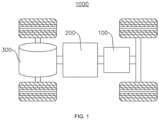
- the electric device is a vehicle 1000 as an example.
- FIG. 1 is a schematic diagram of a structure of a vehicle 1000 provided in some embodiments of the present disclosure.
- the vehicle 1000 can be a gasoline-powered car, a natural gas car, or a new energy vehicle.
- the new energy vehicles can be pure electric cars, hybrid cars, extended-range cars, etc.
- a battery 100 is provided inside the vehicle 1000, wherein the battery 100 can be arranged at the bottom, front, or rear of the vehicle 1000.
- the battery 100 is configured to provide power for the vehicle 1000.
- the battery 100 can serve as the operational power source for the vehicle 1000.
- the vehicle 1000 also comprises a controller 200 and a motor 300.
- the controller 200 is configured to manage the supply of power from the battery 100 to the motor 300, e.g., for working power requirements for starting, navigating, and driving the vehicle 1000.
- the battery 100 serves not only as the operational power source for the vehicle 1000 but also as the driving power source for the vehicle 1000. It can replace or partially substitute for conventional fuels like gasoline or natural gas to provide driving propulsion for the vehicle 1000.
- FIG. 2 is an exploded view of the structure of a battery 100 provided in some embodiments of the present disclosure
- FIG. 3 is a schematic diagram of a structure of a battery cell 20 provided in some embodiments of the present disclosure.
- the battery 100 comprises a box 10 and a battery cell 20, wherein the box 20 is housed the battery cell 10.
- the box 10 includes a box body 11, wherein the box body 11 is configured to provide an assembly space for the battery cell 20, and the box body 11 can be of various structures.
- the box body 11 comprises a first portion 111 and a second portion 112.
- the second portion 112 is capped over the first portion 111.
- the first portion 111, and the second portion 112 together define an assembly space for accommodating the battery cell 20.
- the first portion 111 can be a hollow structure opening on one side, and the second portion 112 can be a plate-like structure.
- the second portion 112 is capped over an open side of the first portion 111 so that the first portion 111 and the second portion 112 together define an assembly space for accommodating the battery cell 20.
- first portion 111 and the second portion 112 can both be hollow structures opening on one side.
- the open side of the second portion 112 is capped over the open side of the first portion 111.
- the box 11 formed by the first portion 111 and the second portion 112 can be of a variety of shapes, e.g., cylindrical, rectangular, etc. Exemplarily, in FIG. 2 , the box body 11 is of rectangular structure.
- the battery cell 20 can be one or multiple. If there are multiple battery cells 20 comprised in the battery 100, the multiple battery cells 20 can be connected in series, parallel, or hybrid. A hybrid connection refers to having both series and parallel connections among multiple battery cells 20.
- the multiple battery cells 20 can be directly connected in series, parallel, or a combination thereof, and then the unit composed of these multiple battery cells 20 can be placed inside the box 10.
- the battery 100 can also be in the form that, the multiple battery cells 20 can be first connected in series, parallel, or a mixed connection to form battery modules, and then the multiple battery modules can be connected in series, parallel, or a mixed connection to form an overall structure, which is accommodated within the box 10.
- the battery 100 can also comprise other structures.
- the battery 100 can also comprise a busbar component, configured for achieving an electrical connection between the multiple battery cells 20.
- the battery cell 20 is provided with a pressure relief mechanism 21.
- the pressure relief mechanism 21 is located on one side of the battery cell 20.
- the pressure relief mechanism 21 is configured to release the internal pressure of the battery cell 20.
- the pressure relief mechanism 21 is configured to release emissions from the interior of the battery cell 20, such as high-temperature smoke, when the battery cell 20 experiences thermal runaway.
- the pressure relief mechanism 21 can be of various components such as explosion-proof valves, burst discs, gas valves, relief valves, or safety valves, among others.
- Each battery cell 20 can be a secondary battery or a primary battery. It can also be a lithium-sulfur battery, sodium-ion battery, magnesium-ion battery, or other types, but is not limited to these.
- the battery cell 20 can have various shapes such as cylindrical, flat, rectangular, or other shapes. Exemplarily, in FIG. 3 , the battery cell 20 is of a cylindrical structure.
- the box 10 comprises at least one exhaust component 12.
- the exhaust component 12 is provided inside the box body 11.
- the at least one exhaust component 12 is configured to partition the interior of the box body 11 into multiple containment cavities 13 configured for accommodating battery cells 20.
- the exhaust component 12 is configured to accommodate the emissions, such as high-temperature smoke, released by the pressure relief mechanism 21 of the battery cell 20 during thermal runaway.
- one side of the battery cell 20 providing the pressure relief mechanism 21 abuts against the exhaust component 12 so as to facilitate the discharge of emissions released by the pressure relief mechanism 21 of the battery cell 20 into the exhaust component 12.
- the side of the battery cell 20 providing the pressure relief mechanism 21 can be arranged facing either the first portion 111 or the second portion 112.
- the exhaust component 12 is provided within the first portion 111 of the box body 11.
- FIG. 4 is a schematic diagram of a structure of the exhaust component 12 provided in some embodiments of the present disclosure
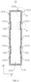
- FIG. 5 is a sectional view of the exhaust component 12 provided in some embodiments of the present disclosure.
- the present disclosure provides an exhaust component 12, wherein the exhaust component 12 comprises a main body part 121 and a one-way guiding part 122.
- the main body part 121 is therein provided with an exhaust chamber 1211, and the main body part 121 is provided with a first surface 1212, wherein the first surface 1212 is provided with ventilation holes 1213 communicating with the exhaust chamber 1211.
- the one-way guiding part 122 is arranged on the main body part 121.
- the one-way guiding part 122 is configured to allow emissions released by the pressure relief mechanism 21 of the battery cell 20 to enter the exhaust chamber 1211 through the ventilation holes 1213 and is also configured to prevent the emissions within the exhaust chamber 1211 from being discharged through the ventilation holes 1213.
- the first surface 1212 is one of the outer surfaces of the main body part 121.
- the exhaust chamber 1211 of the main body part 121 serves to house the emissions released by the pressure relief mechanism 21 of the battery cell 20.
- the exhaust chamber 1211 can be communicated with the external environment through the box 10 of the battery 100 to discharge emissions released by the pressure relief mechanism 21 to the outside of the battery 100. It can also not be in communication with the external environment so that the emissions released by the pressure relief mechanism 21 are housed in the exhaust chamber 1211.
- the one-way guiding part 122 is configured to allow emissions released by the pressure relief mechanism 21 of the battery cell 20 to enter the exhaust chamber 1211 through the ventilation holes 1213 and is also configured to prevent the emissions within the exhaust chamber 1211 from being discharged through the ventilation holes 1213. That is, the one-way guiding part 122 serves to allow only a one-way flow of the emissions released by the pressure relief mechanism 21. In other words, only the emissions released by the pressure relief mechanism 21 are allowed to enter from the containment cavity 13 within the box 10 through the ventilation holes 1213 into the exhaust chamber 1211 of the main body part 121.
- the one-way guiding part 122 can be of various structures, such as an airway one-way valve, a one-way flow diaphragm, or a one-way flow tube.
- the battery 100 provided with such an exhaust component 12 allows emissions released by the pressure relief mechanism 21 of the battery cell 20 to enter the exhaust chamber 1211 through the ventilation holes 1213 in case of thermal runaway of the battery cell 20. This achieves the function of directing the emissions released by the battery cell 20 in a controlled manner.
- the main body part 121 is provided with a one-way guiding part 122, wherein the one-way guiding part 122 can allow emissions to enter the exhaust chamber 1211 through the ventilation holes 1213 and prevent emissions from flowing out of the exhaust chamber 1211 to the external of the exhaust component 12.
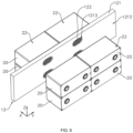
- FIG. 6 is a schematic diagram of an assembly of the exhaust component 12 with the battery cell 20 provided in some embodiments of the present disclosure.
- first surface 1212 is provided with multiple ventilation holes 1213, and the one-way guiding part 122 seals the ventilation holes 1213.
- the one-way guiding part 122 corresponds one-to-one with the ventilation holes 1213.
- the one-way guiding part 122 is configured to be triggered by emissions released by the pressure relief mechanism 21 arranged oppositely so as to open the ventilation holes 1213.
- the first surface 1212 is a surface of the side of the main body part 121 in the first direction X.
- the ventilation holes 1213 are configured to be arranged oppositely to the pressure relief mechanism 21 along the first direction X. That is, each ventilation hole 1213 is arranged oppositely to the pressure relief mechanism 21 of one battery cell 20 along the first direction X. In other words, the pressure relief mechanism 21 of each battery cell 20 is aligned with one ventilation hole 1213 along the first direction X.
- the one-way guiding part 122 functions to seal the ventilation hole 1213 and opens the ventilation hole 1213 under the action of the emissions released by the pressure relief mechanism 21.
- the emissions released by the pressure relief mechanism 21 of the battery cell 20 will impact the ventilation holes 1213, thereby triggering the one-way guiding part 122 to open the ventilation holes 1213. This allows the emissions to enter the exhaust chamber 1211 through the ventilation holes 1213.
- the ways to seal the ventilation holes 1213 with the one-way guiding part 122 can be various.
- the one-way guiding part 122 can seal the ventilation holes 1213 by covering the ventilation holes 1213. That is, the projection of the one-way guiding part 122 in the first direction X is greater than the ventilation holes 1213.
- the one-way guiding part 122 can also seal the ventilation holes 1213 in a manner of being provided within the ventilation holes 1213 to seal the ventilation holes 1213.
- the one-way guiding part 122 is triggered by the impact of the emissions released by the pressure relief mechanism 21.
- the triggering function of the one-way guiding part 122 can also be achieved through a control mechanism.
- a control mechanism is provided within the box 10 of the battery 100. The control mechanism is configured to detect the use of the pressure relief mechanism 21 of the battery cell 20. When the control mechanism detects the triggering and release of the internal pressure of the battery cell 20 by the pressure relief mechanism 21, the control mechanism can control the one-way guiding part 122 to open the ventilation holes 1213, thus realizing the triggering function of the one-way guiding part 122.
- the one-way guiding part 122 is able to prevent emissions within the exhaust chamber 1211 from flowing out of the exhaust chamber 1211 through other ventilation holes 1213 to the external environment of the main body part 121.
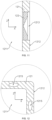
- FIG. 7 is a partially enlarged view at A of the exhaust component 12 shown in FIG. 5 .
- the one-way guiding part 122 covers the ventilation holes 1213 and the one-way guiding part 122 is configured to detach from the main body part 121 under the impact of emissions released by the pressure relief mechanism 21 so as to open the ventilation holes 1213.
- the one-way guiding part 122 covers the ventilation holes 1213, that is to say, along the first direction X, the one-way guiding part 122 completely covers the ventilation holes 1213 to seal the ventilation hole 1213.
- the one-way guiding part 122 is configured to detach from the main body part 121 under the impact of emissions released by the pressure relief mechanism 21.
- the emissions released by the pressure relief mechanism 21 impact the one-way guiding part 122 so as to cause the one-way guiding part 122 to detach from the main body part 121 and no longer cover the ventilation hole 1213, thereby opening the ventilation hole 1213.
- the one-way guiding part 122 can be connected to the cavity wall surface of the exhaust chamber 1211 to cover the ventilation hole 1213, or it can be connected to the hole wall surface of the ventilation hole 1213 to achieve the cover of the ventilation hole 1213.
- the one-way guiding part 122 can be connected to the main body part 121 using methods such as adhesion or clamping, thereby allowing the one-way flow part 122 to better detach from the main body part 121 under the impact of the emissions released by the pressure relief mechanism 21.
- the material of the one-way guiding part 122 can be heat-resistant, such as steel, mica, or ceramic, thus ensuring that the one-way guiding part 122 does not melt under the high-temperature impact of the emissions released by the pressure relief mechanism 21. Therefore, the normal operation of the one-way flow part 122 is ensured.
- the one-way guiding part 122 is configured to seal the ventilation holes 1213 in a manner that covers the ventilation holes 1213. Moreover, the main body part 121 can be disengaged under the impact of the emissions released by the corresponding pressure relief mechanism 21, thus achieving the functionality of opening the ventilation holes 1213 triggered by the emissions released by the pressure relief mechanism 21.
- the structure is simple and easy to implement and manufacture.
- the one-way guiding part 122 is a plate-like structure that covers the ventilation holes 1213.
- the structure of the one-way guiding part 122 is advantageous in that it facilitates the one-way guiding part 122 to cover the ventilation holes 1213, thus providing a relatively good sealing effect on the ventilation holes 1213. Additionally, it optimizes the space occupied by the one-way guiding part 122.
- the ventilation holes 1213 penetrate a cavity wall surface of the exhaust chamber 1211, and the one-way guiding part 122 is connected to the cavity wall surface of the exhaust chamber 1211.
- the one-way guiding part 122 is connected to the cavity wall surface of the exhaust chamber 1211. That is to say, the one-way flow part 122 is arranged inside the exhaust chamber 1211 and is connected to the cavity wall surface of the exhaust chamber 1211. This allows the one-way guiding part 122 to cover the ventilation holes 1213 from the interior of the exhaust chamber 1211, thereby achieving the sealing of the ventilation holes 1213.
- the one-way guiding part 122 is adhered to the cavity wall surface of the exhaust chamber 1211, thereby enabling the effective detachment of the one-way guiding part 122 from the main body part 121 when the emissions released by the pressure relief mechanism 21 impacts the one-way guiding part 122 from the outside of the main body part 121.
- the one-way guiding part 122 increases the pressure of the one-way guiding part 122 against the cavity wall surface of the exhaust chamber 1211, thereby effectively preventing the backflow of the emissions.
- the one-way guiding part 122 can also be connected to the cavity wall surface of the exhaust chamber 1211 by a snap connection.
- the ventilation holes 1213 penetrating the cavity wall surface of the exhaust chamber 1211 are covered by arranging the one-way guiding part 122 on the cavity wall surface of the exhaust chamber 1211.
- the structure of the exhaust component 12 is advantageous in that, on the one hand, it facilitates the one-way guiding part 122 to detach better from the cavity wall surface of the exhaust chamber 1211 under the impact of emissions released by the pressure relief mechanism 21, thus achieving the function of opening the ventilation holes 1213.
- the emissions impact the one-way guiding part 122 covering other ventilation holes 1213 from inside the exhaust chamber 1211, it tightly presses the one-way guiding part 122 onto the cavity wall surface of the exhaust chamber 1211. This enhances the sealing effect of the one-way guiding part 122 on the ventilation holes 1213, thus eliminating the occurrence of backflow of the emissions from other ventilation holes 1213.
- FIG. 8 is a sectional view of the exhaust component 12 provided in some other embodiments of the present disclosure
- FIG. 9 is a partially enlarged view at B of the exhaust component 12 shown in FIG. 8
- the cavity wall surface of the exhaust chamber 1211 is provided with a receiving groove 1214, wherein the receiving groove 1214 communicates with the ventilation holes 1213 and the exhaust chamber 1211. At least a portion of the one-way guiding part 122 is accommodated within the receiving groove 1214.
- the cavity wall surface of the exhaust chamber 1211 is provided with a receiving groove 1214, wherein the receiving groove 1214 communicates with the ventilation holes 1213 and the exhaust chamber 1211.
- the ventilation hole 1213 penetrates the groove bottom wall of the groove so that the ventilation hole 1213 is in communication with the exhaust chamber 1211 through the groove.
- the one-way guiding part 122 can be connected to the groove bottom wall of the groove or the groove side wall of the groove. The connection method can be achieved through adhesion or snap, thereby achieving covering for the ventilation hole 1213.
- the one-way guiding part 122 is accommodated in the receiving groove 1214.
- the one-way guiding part 122 can be either entirely accommodated within the receiving groove 1214 or partially accommodated within the receiving groove 1214, which means that the one-way guiding part 122 has a portion along the first direction X that extends from the groove into the exhaust chamber 1211.
- the cavity wall surface of the exhaust chamber 1211 is provided with a groove configured for accommodating the one-way guiding part 122.
- the ventilation hole 1213 is in communication with the exhaust chamber 1211 through the groove.
- the exhaust component 12 by using this structure, not only ensures the sealing of the ventilation holes 1213 by the one-way guiding part 122 but also enhances the assembly stability of the one-way guiding part 122 provided on the main body part 121. This reduces the risk of the one-way guiding part 122 unintentionally detaching from the main body part 121 during use due to vibrations or other environmental factors. Consequently, it effectively minimizes the occurrence of the one-way guiding part 122 mistakenly opening the ventilation holes 1213.
- FIG. 10 is a sectional view of the exhaust component 12 provided in some embodiments of the present disclosure
- FIG. 11 is a partially enlarged view at C of the exhaust component 12 shown in FIG. 10
- the one-way guiding part 122 is a one-way valve arranged within the ventilation holes 1213.
- the one-way guiding part 122 can also seal the ventilation holes 1213 in a manner of being provided within the ventilation holes 1213.
- the specific structure of the one-way valve can be found in the related technology and will not be repeated here.
- the one-way guiding part 122 can be an air path one-way valve, and its structure can be of various types, such as a spring-type one-way valve, gravity-type one-way valve, or diaphragm-type one-way valve, among others.
- the one-way guiding part 122 By configuring the one-way guiding part 122 as a one-way valve located within the ventilation hole 1213, it achieves the functionality of the one-way guiding part 122 opening the ventilation holes 1213 under the impact of the emissions released by the pressure relief mechanism 21 so as to prevent the backflow of emissions within the exhaust chamber 1211.
- the one-way guiding part 122 with this structure possesses a better effect of anti-backflow.
- the main body part 121 is provided with two first surfaces 1212 opposite each other, and both first surfaces 1212 are provided with ventilation holes 1213.
- the main body part 121 is provided with two first surfaces 1212 opposite each other, and both first surfaces 1212 are provided with ventilation holes 1213.
- the main body part 121 is provided with ventilation holes 1213 communicating with the exhaust chamber 1211 on both sides along the first direction X.
- the main body part 121 is provided with a first surface 1212 on each side along the first direction X, and both first surfaces 1212 are provided with ventilation holes 1213.
- the main body part 121 is provided with ventilation holes 1213 communicating with the exhaust chamber 1211 on both sides along the first direction X so as to allow the assembly of battery cell 20 on both sides of the exhaust component 12, thus enabling a single exhaust component 12 to adapt to two rows of battery cells 20 arranged oppositely to the pressure relief mechanism 21. Further, this is advantageous for saving production costs for batteries 100 provided with the exhaust component 12 and optimizing the arrangement of battery cells 20 within the battery 100.
- the first surface 1212 is a surface having the largest area among the outer surfaces of the main body part 121.
- the main body part 121 is a rectangular structure, and the first direction X is a thickness direction of the main body part 121. Therefore, the first surface 1212 is a surface having the largest area among the outer surfaces of the main body part 121.
- the first surface 1212 provided with ventilation holes 1213 is the surface having the largest area among the outer surfaces of the main body part 121.
- the exhaust component 12 with this structure is advantageous in that, on the one hand, it facilitates the arrangement on the first surface 1212 of the ventilation holes 1213 provided oppositely to the pressure relief mechanism 21 of the battery cell 20; on the other hand, the first surface 1212 can be provided for a side of the battery cell 20 arranged with the pressure relief mechanism 21, and thus, this facilitates the discharge of emissions released by the pressure relief mechanism 21 through the ventilation holes 1213 into the exhaust chamber 1211 of the main body part 121.
- FIG. 12 is a partially enlarged view at D of the exhaust component 12 shown in FIG. 5 .
- the main body part 121 is provided therein with a medium channel 1215.
- the medium channel 1215 and the exhaust chamber 1211 are not in communication with each other, and the medium channel 1215 is configured to accommodate a refrigerant to manage the temperature of the battery cell 20.
- the medium channel 1215 and the exhaust chamber 1211 are not in communication with each other, that is to say, the medium channel 1215 and the exhaust chamber 1211 are provided independently of each other and do not interfere with each other.
- one or multiple medium channels 1215 can be provided on the main body part 121.
- the main body part 121 is provided with multiple medium channels 1215 extending in an extension direction of the main body part 121.
- the medium channel 1215 is configured to accommodate the refrigerant, thus enabling the function of cooling down the battery cell 20 by injecting the refrigerant into the medium channel 1215 so as to realize the management of the temperature of the battery cell 20.
- the refrigerant can be a gas, such as air or hydrogen, or it can be a liquid, such as water, saline solution, or liquid nitrogen, and so on.
- introducing a refrigerant into the medium channel 1215 can manage the temperature of the battery cell 20.
- This enables a structure where the exhaust component 12 integrates the containment of emissions released by the pressure relief mechanism 21 of the battery cell 20 and the thermal management for the battery cell 20. This is advantageous for optimizing the internal space of the battery 100 provided with the exhaust component 12.
- the embodiments of the present disclosure also provide a box 10, wherein the box 10 comprises a box body 11 and the exhaust component 12 according to any one of the embodiments above.
- the exhaust component 12 is provided inside the box body 11.
- the exhaust component 12 is configured to partition the interior of the box body 11 into multiple containment cavities 13, wherein the containment cavities 13 are configured for accommodating battery cells 20.
- the exhaust component 12 is provided within the first portion 111 of the box body 11 so as to partition the interior of the box body 11 into multiple containment cavities 13.
- the number of exhaust components 12 provided within the box body 11 can be one or more.
- the exhaust component 12 partitions the interior of the box body 11 into two containment cavities 13 so that the exhaust component 12 and the first portion 111 form a structure of the Chinese character " ".
- the multiple exhaust components 12 can be arranged at intervals along the length direction or width direction of the box body 11 so that the exhaust component 12 and the first portion 111 form a structure of Chinese character " ", and the like.
- multiple exhaust components 12 can also be arranged crossing each other within the first portion 111 so that the exhaust component 12 and the first portion 111 form a structure of the Chinese character " ", and the like.
- FIG. 2 two exhaust components 12 are provided, wherein the two exhaust components 12 are arranged at intervals along the first direction X so as to partition the interior of the box body 11 into three containment cavities 13.
- the embodiments of the present disclosure further provide a battery 100, wherein the battery 100 comprises a battery cell 20 and the box 10 according to any one of the embodiments above.
- the battery cell 20 is housed in the containment cavity 13.
- the battery cell 20 is provided with a pressure relief mechanism 21, wherein the pressure relief mechanism 21 is configured to release the internal pressure of the battery cell 20.
- the form in which the battery cell 20 is assembled into the containment cavity 13 can be various. For example, it can be with the side of the battery cell 20 arranged with the pressure relief mechanism 21 to face the first surface 1212 of the exhaust component 12. It can also be with the side of the battery cell 20 arranged with the pressure relief mechanism 21 to face either the first portion 111 or the second portion 112.
- one side of the main body part 121 forms the first surface 1212, and the pressure relief mechanism 21 is arranged on one side of the battery cell 20 along the first direction X.
- the pressure relief mechanism 21 is arranged oppositely to the ventilation holes 1213.
- the pressure relief mechanism 21 is arranged opposite to the ventilation hole 1213, meaning that along the first direction X, the pressure relief mechanism 21 is arranged in alignment with the ventilation hole 1213.
- the side of the battery cell 20 arranged with the pressure relief mechanism 21 can abut against the first surface 1212 of the main body part 121, or, a gap can be provided in the first surface 1212 of the main body part 121 in the first direction X.
- the side of the battery cell 20 arranged with the pressure relief mechanism 21 can abut against the first surface 1212 of the main body part 121. This helps improve the assembly stability between the battery cell 20 and the exhaust component 12 and facilitates the discharge of the emissions released by the pressure relief mechanism 21 through the ventilation holes 1213 into the exhaust chamber 1211 of the main body part 121.
- One side of the main body part 121 forms the first surface 1212 along the first direction X, meaning that the ventilation holes 1213 are arranged on one side of the main body part 121 along the first direction X.
- the pressure relief mechanism 21 is arranged on one side of the battery cell 20 along the first direction X, thus allowing the pressure relief mechanism 21 to be arranged relative to the ventilation holes 1213 on the main body part 121. This facilitates emissions released by the pressure relief mechanism 21 to be discharged directly into the exhaust chamber 1211 of the main body part 121 through the ventilation holes 1213 during the thermal runaway of the battery cell 20, thus helping eliminate the occurrence of the spread of emissions released by the pressure relief mechanism 21 within the box 10.
- the battery 100 comprises multiple battery cells 20 arranged along a second direction Y, and the main body part 121 extends along the second direction Y.
- the ventilation holes 1213 correspond one-to-one with the pressure relief mechanisms 21, and the second direction Y is perpendicular to the first direction X.
- the main body part 121 is a rectangular structure extending along the second direction Y, and the ventilation holes 1213 are provided on a side of the main body part 121 in the thickness direction of the main body part 121.
- the main body part 121 is provided with a first surface 1212 on each side along the first direction X, and each first surface 1212 is provided with the ventilation hole 1213.
- both sides of the body part 121, along the first direction X, are provided with battery cell 20.
- the pressure relief mechanisms 21 of the battery cells 20 arranged on both sides of the main body part 121 along the first direction X are provided facing each other.
- the battery cell 20 is rectangular in structure, and the battery cell 20 is provided with a second surface 22.
- the second surface 22 is a surface having the largest area among the outer surfaces of the battery cell 20, and the second surface 22 is parallel to both the first direction X, and the second direction Y.
- the second surface 22 is a surface having the largest area among the outer surfaces of the battery cell 20, meaning that the second surface 22 is the surface of the battery cell 20 in the thickness direction of the battery cell 20.
- the second surface 22 is parallel to the first direction X and the second direction Y, meaning that the plane defined by the first direction X and the second direction Y is parallel to the second surface 22.
- the thickness direction of the battery cell 20 is perpendicular to both the first direction X and second direction Y.
- the second direction Y is the length direction of the battery cell 20
- the pressure relief mechanism 21 is provided on one side of the battery cell 20 in the width direction (first direction X) of the battery cell 20.
- the second direction Y can also be the thickness direction of the battery monomer 20, meaning that the second surface 22 is perpendicular to the second direction Y.
- the multiple battery cells 20 are arranged along the thickness direction of the battery cell 20.
- the battery cell 20 is configured in a rectangular structure and the second surface 22 having the largest surface area on the outer surface of the battery cell 20 is parallel to both the first direction X and second direction Y.
- the thickness direction of the battery cell 20 is perpendicular to both the first direction X and the second direction Y so as to ensure that a direction in which the battery cell 20 is arranged along the second direction Y is the length direction or width direction of the battery cell 20.
- the battery 100 adopting the structure effectively increases the spacing between the pressure relief mechanisms 21 of the battery cells 20 in the second direction Y, thereby facilitating an increase in the distance of the ventilation holes 1213 in the second direction Y.
- the battery 100 includes multiple rows of battery cells 20 arranged along a third direction Z.
- Each row of battery cells 20 includes multiple battery cells 20 arranged along the second direction Y, and the third direction Z is perpendicular to the first direction X and the second direction Y.
- the third direction Z is perpendicular to both the first direction X and the second direction Y.
- the third direction Z is perpendicular to the second surface 22 of the battery cell 20, meaning that the third direction Z is the thickness direction of the battery cell 20.
- the battery 100 includes two rows of battery cells 20 arranged along the third direction Z.
- the battery 100 includes three rows, four rows, five rows, or six rows of battery cells 20 arranged along the third direction Z.
- the multiple battery cells 20 within the battery 100 are arranged in multiple rows along the third direction Z, and each row of battery cells 20 includes multiple battery cells 20 arranged along the second direction Y.
- each row of battery cells 20 includes multiple battery cells 20 arranged along the second direction Y.
- the embodiments of the present disclosure provide an electric device, wherein the electric device comprises a battery 100 of any of the above solutions, and the battery 100 is configured to provide electrical energy to the electric device.
- the electric device can be any of the above-mentioned devices or systems that apply the battery 100.
- the present disclosure provides an exhaust component 12, wherein the exhaust component 12 comprises a main body part 121 and a one-way guiding part 122.
- the main body part 121 is therein provided with an exhaust chamber 1211, and along the first direction X, both sides of the main body part 121 are provided with first surfaces 1212, wherein the first surfaces 1212 are provided with multiple ventilation holes 1213 communicating with the exhaust chamber 1211.
- the ventilation holes 1213 are configured to be arranged oppositely to the pressure relief mechanism 21 along the first direction X.
- the cavity wall surface of the exhaust chamber 1211 is provided with a receiving groove 1214, wherein the receiving groove 1214 communicates with the ventilation holes 1213 and the exhaust chamber 1211.
- the one-way guiding parts 122 are provided in one-to-one correspondence with the ventilation holes 1213, the one-way guiding part 122 is connected to the main body part 121 and at least a portion of the one-way guiding part 122 is accommodated in the receiving groove 1214.
- the one-way guiding part 122 covers the ventilation holes 1213 and the one-way guiding part 122 is configured to detach from the main body part 121 under the impact of emissions released by the pressure relief mechanism 21 so as to open the ventilation holes 1213.
- the main body part 121 is provided therein with a medium channel 1215.
- the medium channel 1215 and the exhaust chamber 1211 are not in communication with each other, and the medium channel 1215 is configured to accommodate a refrigerant to manage the temperature of the battery cell 20.
Landscapes
- Chemical Kinetics & Catalysis (AREA)
- Electrochemistry (AREA)
- General Chemical & Material Sciences (AREA)
- Chemical & Material Sciences (AREA)
- Engineering & Computer Science (AREA)
- Sustainable Development (AREA)
- Life Sciences & Earth Sciences (AREA)
- Sustainable Energy (AREA)
- Power Engineering (AREA)
- Transportation (AREA)
- Mechanical Engineering (AREA)
- Manufacturing & Machinery (AREA)
- Aviation & Aerospace Engineering (AREA)
- Gas Exhaust Devices For Batteries (AREA)
- Battery Mounting, Suspending (AREA)
Abstract
Description
- The present disclosure relates to the technology field of batteries, specifically to an exhaust component, a box, a battery, and an electric device.
- In recent years, new energy vehicles have experienced a leapfrog development. In the field of electric vehicles, power batteries serve as the energy source for electric vehicles and play an irreplaceable important role. With the strong promotion of new energy vehicles, the demand for power battery products is also increasing. The battery, as the core component of new energy vehicles, has high requirements in terms of both service life and safety. The battery is composed of multiple battery cells, and the thermal runaway of a battery cell is one of the crucial factors threatening the safety performance of the battery. However, in the battery of the existing technologies, the emissions released from the internal of the battery cell during its thermal runaway can still pose significant safety hazards, such as high-temperature smoke, which is not conducive to consumer safety during use.
- The embodiments of the present disclosure provide an exhaust component, a box, a battery, and an electric device, capable of effectively reducing the safety hazards of the battery during use.
- In the first aspect, the embodiments of the present disclosure provide an exhaust component comprising a main body part and a one-way guiding part. The main body part is therein provided with an exhaust chamber, and the main body part is provided with a first surface, wherein the first surface is provided with ventilation holes communicating with the exhaust chamber. The one-way guiding part is arranged on the main body part. The one-way guiding part is configured to allow emissions released by the pressure relief mechanism of the battery cell to enter the exhaust chamber through the ventilation holes and is also configured to prevent the emissions within the exhaust chamber from being discharged through the ventilation holes.
- In the above technical solution, by arranging the ventilation holes that communicate with the exhaust chamber on the first surface of the main body part, the battery provided with such an exhaust component allows emissions released by the pressure relief mechanism of the battery cell to enter the exhaust chamber through the ventilation holes in case of thermal runaway of the battery cell. This achieves the function of directing the emissions released by the battery cell in a controlled manner. Furthermore, the main body part is provided with a one-way guiding part, wherein the one-way guiding part can allow emissions to enter the exhaust chamber through the ventilation holes and prevent emissions from flowing out of the exhaust chamber to the external of the exhaust component. It ensures that the emissions released by the pressure relief mechanism will not flow out from other ventilation holes after entering the exhaust chamber through the ventilation holes, which eliminates the occurrence of backflow of emissions released into the exhaust chamber by the pressure relief mechanism. Thus, it can reduce the risk of backflow of emissions within the exhaust chamber, preventing the further spread of emissions inside the battery. This contributes to improving the usage safety of batteries comprising the exhaust component.
- In some embodiments, along a first direction, one side of the main body part forms a first surface, and the ventilation holes are configured to be arranged oppositely to the pressure relief mechanism along the first direction. The first surface is provided with multiple ventilation holes, and the one-way guiding part seals the ventilation holes. The one-way guiding part corresponds one-to-one with the ventilation holes. The one-way guiding part is configured to be triggered by emissions released by the pressure relief mechanism arranged oppositely so as to open the ventilation holes.
- In the above technical solution, by arranging multiple ventilation holes along the first direction on the first surface of the main body part corresponding to the pressure relief mechanism of the battery cell, and by sealing each ventilation hole through a one-way guiding part, emissions released by the pressure relief mechanism of the battery cell during thermal runaway can directly impact the ventilation holes and trigger the one-way guiding part to open the ventilation holes. This allows emissions released by the pressure relief mechanism of the battery cell to be discharged directly into the exhaust chamber through the ventilation holes. Simultaneously, the one-way guiding part is able to prevent emissions within the exhaust chamber from flowing out of the exhaust chamber through other ventilation holes to the external environment of the main body part. It ensures that the emissions released by the pressure relief mechanism will not flow out from other ventilation holes after entering the exhaust chamber through the ventilation holes, which eliminates the occurrence of backflow of emissions released into the exhaust chamber by the pressure relief mechanism. Thus, while ensuring that the size of the space of the exhaust chamber inside the exhaust component is sufficient, the risk of further spreading of emissions inside the battery can be effectively reduced. Additionally, it helps eliminate the phenomenon of emissions impacting other battery cells through other ventilation holes, thereby reducing the risk of large-area ignition and explosion of battery cells due to the thermal runaway of individual battery cells of the battery.
- In some embodiments, the one-way guiding part covers the ventilation holes and the one-way guiding part is configured to detach from the main body part under the impact of emissions released by the pressure relief mechanism so as to open the ventilation holes.
- In the above technical solution, the one-way guiding part is configured to seal the ventilation holes in a manner that covers the ventilation holes. Moreover, the main body part can be disengaged under the impact of the emissions released by the corresponding pressure relief mechanism, thus achieving the functionality of opening the ventilation holes triggered by the emissions released by the pressure relief mechanism. The structure is simple and easy to implement and manufacture.
- In some embodiments, the one-way guiding part is a plate-like structure that covers the ventilation holes.
- In the above technical solution, by providing the one-way guiding part, configured to cover the ventilation holes, as a plate-like structure, the structure of the one-way guiding part is advantageous in that it facilitates the one-way guiding part to cover the ventilation holes, thus providing a relatively good sealing effect on the ventilation holes. Additionally, it optimizes the space occupied by the one-way guiding part.
- In some embodiments, the ventilation holes penetrate a cavity wall surface of the exhaust chamber, and the one-way guiding part is connected to the cavity wall surface of the exhaust chamber.
- In the above technical solution, the ventilation holes penetrating the cavity wall surface of the exhaust chamber are covered by arranging the one-way guiding part on the cavity wall surface of the exhaust chamber. The structure of the exhaust component is advantageous in that, on the one hand, it facilitates the one-way guiding part to detach better from the cavity wall surface of the exhaust chamber under the impact of emissions released by the pressure relief mechanism, thus achieving the function of opening the ventilation holes. On the other hand, when the emissions impact the one-way guiding part covering other ventilation holes from inside the exhaust chamber, it tightly presses the one-way guiding part onto the cavity wall surface of the exhaust chamber. This enhances the sealing effect of the one-way guiding part on the ventilation holes, thus eliminating the occurrence of backflow of the emissions from other ventilation holes.
- In some embodiments, the cavity wall surface of the exhaust chamber is provided with a receiving groove, wherein the receiving groove communicates with the ventilation holes and the exhaust chamber. At least a portion of the one-way guiding part is accommodated within the receiving groove.
- In the above technical solution, the cavity wall surface of the exhaust chamber is provided with a groove configured for accommodating the one-way guiding part. Additionally, the ventilation holes and the exhaust chamber are communicated through the groove. In other words, the ventilation holes penetrate the groove bottom wall of the groove. The exhaust component, by using this structure, not only ensures the sealing of the ventilation holes by the one-way guiding part but also enhances the assembly stability of the one-way guiding part provided on the main body part. This reduces the risk of the one-way guiding part unintentionally detaching from the main body part during use due to vibrations or other environmental factors. Consequently, it effectively minimizes the occurrence of the one-way guiding part mistakenly opening the ventilation holes.
- In some embodiments, the one-way guiding part is a one-way valve arranged within the ventilation holes.
- In the above technical solution, by configuring the one-way guiding part as a one-way valve located within the ventilation hole, it achieves the functionality of the one-way guiding part opening the ventilation holes under the impact of the emissions released by the pressure relief mechanism so as to prevent the backflow of emissions within the exhaust chamber. The one-way guiding part of the structure possesses a better effect of anti-backflow.
- In some embodiments, along the first direction, the main body part is provided with two first surfaces opposite each other, and both first surfaces are provided with ventilation holes.
- In the above technical solution, the main body part is provided with a first surface on each side along the first direction, and both first surfaces are provided with ventilation holes. In other words, the main body part is provided with ventilation holes communicating with the exhaust chamber on both sides along the first direction so as to allow the assembly of battery cells on both sides of the exhaust component, thus enabling a single exhaust component to adapt to two rows of battery cells arranged oppositely to the pressure relief mechanism. Further, this is advantageous for saving production costs for batteries provided with this exhaust component and optimizing the arrangement of battery cells within the battery.
- In some embodiments, the first surface is a surface having the largest area among the outer surfaces of the main body part.
- In the above technical solution, where the first surface provided with ventilation holes is the surface having the largest area among the outer surfaces of the main body part, the exhaust component with this structure is advantageous in that, on the one hand, it facilitates the arrangement on the first surface of the ventilation holes provided oppositely to the pressure relief mechanism of the battery cell; on the other hand, the first surface can be provided for a side of the battery cell arranged with the pressure relief mechanism, and thus, this facilitates the discharge of emissions released by the pressure relief mechanism through the ventilation holes into the exhaust chamber of the main body part.
- In some embodiments, further, the main body part is provided therein with a medium channel. The medium channel and the exhaust chamber are not in communication with each other, and the medium channel is configured to accommodate a refrigerant to manage the temperature of the battery cell.
- In the above technical solution, by arranging the medium channel inside the main body part that is in communication with the exhaust chamber, the medium channel and the exhaust chamber are arranged independently and do not interfere with each other. Therefore, introducing a refrigerant into the medium channel can manage the temperature of the battery cell. This enables a structure where the exhaust component integrates the containment of emissions released by the pressure relief mechanism of the battery cell and the thermal management of the battery cell. This is advantageous for optimizing the internal space of the battery provided with the exhaust component.
- In the second aspect, the embodiments of the present disclosure also provide a box, comprising a box body and the aforementioned exhaust component. The exhaust component is provided inside the box body. The exhaust component is configured to partition the interior of the box body into multiple containment cavities, wherein the containment cavities are configured for accommodating battery cells.
- In the third aspect, the embodiments of the present disclosure further provide a battery, comprising a battery cell and the aforementioned box. The battery cell is housed in the containment cavity. The battery cell is provided with a pressure relief mechanism, wherein the pressure relief mechanism is configured to release the internal pressure of the battery cell.
- In some embodiments, along the first direction, one side of the main body part forms the first surface, and the pressure relief mechanism is arranged on one side of the battery cell along the first direction. The pressure relief mechanism is arranged oppositely to the ventilation holes.
- In the above technical solution, one side of the main body part forms the first surface along the first direction, meaning that the ventilation holes are arranged on one side of the main body part along the first direction. Correspondingly, the pressure relief mechanism is arranged on one side of the battery cell along the first direction, thus allowing the pressure relief mechanism to be arranged relative to the ventilation holes on the main body part. This facilitates emissions released by the pressure relief mechanism to be discharged directly into the exhaust chamber of the main body part through the ventilation holes during the thermal runaway of the battery cell, thus helping eliminate the occurrence of the spread of emissions released by the pressure relief mechanism within the box.
- In some embodiments, the battery comprises multiple battery cells arranged along a second direction, and the main body part extends along the second direction. The ventilation holes correspond one-to-one with the pressure relief mechanisms, and the second direction is perpendicular to the first direction.
- In the above technical solution, by arranging multiple battery cells within the battery along the second direction and arranging ventilation holes corresponding one-to-one with the pressure relief mechanisms of multiple battery cells on the main body part extending along the second direction, it can be achieved to have multiple battery cells arranged along the second direction sharing a single exhaust component. This not only reduces the difficulty of assembling between the exhaust component and the battery cells but also helps lower the manufacturing cost of the battery.
- In some embodiments, the battery cell is rectangular in structure, and the battery cell is provided with a second surface. The second surface is a surface having the largest area among the outer surfaces of the battery cell, and the second surface is parallel to both the first direction and the second direction.
- In the above technical solution, the battery cell is configured in a rectangular structure and the second surface having the largest surface area on the outer surface of the battery cell is parallel to both the first direction and second direction. In other words, the thickness direction of the battery cell is perpendicular to both the first direction and second direction so as to ensure that a direction in which the battery cell is arranged along the second direction is the length direction or width direction of the battery cell. The battery adopting the structure effectively increases the spacing between the pressure relief mechanisms of the battery cells in the second direction, thereby facilitating an increase in the distance of the ventilation holes in the second direction. On one hand, this effectively mitigates the case of the insufficient structural strength of the main body part due to the excessive density of ventilation holes in the first direction, thus reducing the risk of damage to the main body part under the high-temperature conditions of emissions released by the pressure relief mechanism. On the other hand, it minimizes the impact of emissions released by the pressure relief mechanism of the battery cell on the one-way guiding parts arranged on adjacent ventilation holes.
- In some embodiments, the battery includes multiple rows of battery cells arranged along a third direction. Each row of battery cells includes multiple battery cells arranged along the second direction, and the third direction is perpendicular to the first direction and second direction.
- In the above technical solution, the multiple battery cells within the battery are arranged in multiple rows along the third direction, and each row of battery cells includes multiple battery cells arranged along the second direction. Thus, it is possible to realize one exhaust component adapted to more battery cells, which is conducive to reducing the manufacturing cost of the battery and saving the internal space of the battery.
- In the fourth aspect, the embodiments of the present disclosure further provide an electric device comprising the battery as described above, wherein the battery is configured to provide electrical energy.
- To more clearly illustrate the technical solutions of the embodiments of the present disclosure, the following will briefly introduce the drawings used in the embodiments. It should be understood that the following drawings only show some embodiments of the present disclosure, and therefore they should not be regarded as a limitation on the scope. Those ordinary skilled in the art can also obtain other related drawings based on these drawings without inventive effort.
-
FIG. 1 is a schematic diagram of a structure of a vehicle provided in some embodiments of the present disclosure; -
FIG. 2 is an exploded view of the structure of a battery provided in some embodiments of the present disclosure; -
FIG. 3 is a schematic diagram of a structure of a battery cell provided in some embodiments of the present disclosure; -
FIG. 4 is a schematic diagram of a structure of an exhaust component provided in some embodiments of the present disclosure; -
FIG. 5 is a sectional view of the exhaust component provided in some embodiments of the present disclosure; -
FIG. 6 is a schematic diagram of an assembly of the exhaust component with the battery cell provided in some embodiments of the present disclosure; -
FIG. 7 is a partially enlarged view at A of the exhaust component shown inFIG. 5 ; -
FIG. 8 is a sectional view of the exhaust component provided in some other embodiments of the present disclosure; -
FIG. 9 is a partially enlarged view at B of the exhaust component shown inFIG. 8 ; -
FIG. 10 is a sectional view of the exhaust component provided in some other embodiments of the present disclosure; -
FIG. 11 is a partially enlarged view at C of the exhaust component shown inFIG. 10 ; and -
FIG. 12 is a partially enlarged view at D of the exhaust component shown inFIG. 5 . - Reference numerals: 1000- vehicle; 100- battery; 10- box; 11- box body; 111- first portion; 112- second portion; 12- exhaust component; 121-main body part; 1211- exhaust chamber; 1212- first surface; 1213- ventilation hole; 1214- receiving groove; 1215- medium channel; 122- one-way guiding part; 13- containment cavity; 20- battery cell; 21- pressure relief mechanism; 22- second surface; 200- controller; 300- motor; X- first direction; Y- second direction; Z- third direction.
- In order to make the objective, technical solution, and advantages of the embodiments of the present disclosure clearer, the following will provide a clear and complete description of the technical solution in the embodiments of the present disclosure, in conjunction with the drawings in the embodiments of the present disclosure. Obviously, the described embodiments are only a part of the embodiments of the present disclosure, rather than all embodiments. Based on the embodiments in the present disclosure, all other embodiments obtained by those of ordinary skill in the art without making inventive efforts are within the scope of protection of the present disclosure.
- Unless otherwise defined, all technical and scientific terms used herein have the same meaning as understood by those skilled in the art of the relevant technical field. The terms used in the summary of the present disclosure are used for the purpose of describing specific embodiments and are not intended to limit the present disclosure. The terms "comprise" and "provide" and their variations, as well as any other variations, are intended to cover non-exclusive inclusion in the summary and the claims of the present disclosure, as well as in the drawings. The terms "first", "second", etc., used in the summary and claims of the present disclosure, or in the above drawings, are used to distinguish between different objects and are not intended to describe a specific sequence or hierarchy.
- The term "embodiment" used in the present disclosure means that specific features, structures, or characteristics described in conjunction with the embodiment can be included in at least one embodiment of the present disclosure. The use of this phrase in various parts of the summary does not necessarily refer to the same embodiment, nor does it imply that these embodiments are mutually exclusive or independent of each other.
- In the description of the present disclosure, it should be noted that, unless otherwise clearly stipulated and limited, the terms "provide", "interconnect", "connect" and "attach" should be understood in a broad sense, for example, it can be a fixed connection, a detachable connection, or an integral connection, and it can be a direct connection, an indirect connection through an intermediary, or an internal communication between two components. Those of ordinary skill in the art can understand the meanings of the above terms in the present disclosure according to specific situations.
- In the present disclosure, the term "and/or" is used as a way to describe the relationship between associated objects, indicating that there can be three possible relationships. For example, "A and/or B" can represent: the presence of A alone, the presence of both A and B, or the presence of B alone. Additionally, the character "/" in the present disclosure generally represents an "or" relationship between the preceding and following associated objects.
- In the embodiments of the present disclosure, identical reference numerals indicate the same components. For the sake of conciseness, detailed explanations of the same components are omitted in different embodiments. It should be understood that the dimensions such as thickness, length, and width of various components in the embodiments of the present disclosure as shown in the drawings, as well as the overall dimensions such as thickness, length, and width of the integrated device, are provided as illustrative examples and should not be construed to limit the scope of the present disclosure.
- In the present disclosure, the term "multiple" refers to two or more (including two).
- In the present disclosure, the battery cell can comprise various types of batteries such as lithium-ion secondary batteries, lithium-ion primary batteries, lithium-sulfur batteries, sodium-ion batteries, magnesium-ion batteries, etc. The embodiments of the present disclosure are not limited to any specific type of battery. The battery cell can have various shapes such as cylindrical, flat, rectangular, or other shapes. The embodiments of the embodiments of the present disclosure do not impose limitations on this aspect either. The battery cells are generally categorized into three packaging types: cylindrical battery cells, prismatic battery cells, and pouch battery cells. The embodiments of the embodiments of the present disclosure do not impose limitations in this regard either.
- The batteries mentioned in the embodiments of the present disclosure refer to a single physical module that comprises one or multiple battery cells to provide higher voltage and capacity. For example, the batteries mentioned in the present disclosure can comprise battery modules or battery packs, and so on. A battery generally comprises a box for encapsulating one or multiple battery cells or multiple battery modules. The box helps to prevent liquids or other foreign substances from affecting the charging or discharging of the battery cells.
- The battery cell comprises a casing, an electrode assembly, and an electrolyte, and the casing is configured to accommodate the electrode assembly and the electrolyte. The electrode assembly is the component within the battery cell where electrochemical reactions occur. The electrode assembly is composed of a positive electrode sheet, a negative electrode sheet, and a separator. The battery cells work primarily on the movement of metal ions between the positive electrode sheet and the negative electrode sheet. The positive electrode sheet comprises a positive current collector and a positive active material layer. The positive electrode active material layer is coated on a surface of the positive electrode current collector, and the positive electrode current collector not coated with the positive electrode active material layer protrudes from the positive electrode current collector coated with the positive electrode active material layer. The positive electrode current collector not coated with the positive electrode active material layer serves as the positive electrode tab. In the case of lithium-ion batteries, the material for the positive electrode current collector can be aluminum, and the positive active material can be lithium cobalt oxide, lithium iron phosphate, lithium manganese oxide, or lithium nickel cobalt manganese oxide, and so on. The negative electrode sheet comprises a negative electrode current collector and a negative electrode active material layer. The negative electrode active material layer is coated on a surface of the negative electrode current collector, and the negative electrode current collector not coated with the negative electrode active material layer protrudes from the negative electrode current collector coated with the negative electrode active material layer. The negative electrode current collector not coated with the negative electrode active material layer serves as the negative electrode tab. The material of the negative electrode current collector can be copper, and the negative active material can be carbon or silicon, and so on. To ensure that there is no fuse blow during high current flow, the number of positive electrode tabs is multiple and stacked together, and the number of negative electrode tabs is multiple and stacked together.
- The material of the separator can be PP (polypropylene), PE (polyethylene), and so on. Furthermore, the electrode assembly can be a wound structure or a stacked structure. The embodiments of the present disclosure are not limited herein.
- Batteries have prominent advantages such as high energy density, low environmental pollution, high power density, long service life, broad applicability, and low self-discharge coefficient. They are an important component of the current development of new energy sources. With the continuous development of battery technology, higher requirements have been put forward in terms of safety in the use of batteries.
- The inventors have found that, for typical batteries, which are composed of multiple battery cells, pressure relief mechanisms are usually provided on the battery cells. This allows the pressure relief mechanisms to release the internal pressure of the battery cell when the battery cells undergo thermal runaway, thus reducing the risk of explosion of the battery cells caused by thermal runaway. However, emissions released by the pressure relief mechanism of individual battery cells during thermal runaway can spread within the battery, such as high-temperature smoke. Thus, it is very easy to trigger a large-area thermal runaway phenomenon of the battery.
- Therefore, to address the issue of the spread of high-temperature smoke generated during the thermal runaway of individual battery cells within the battery, in existing technology, multiple baffles are provided inside the box of the battery. The baffles partition the interior of the box into multiple chambers for accommodating individual battery cells. The baffle is provided therein with an exhaust channel configured for ventilation. Additionally, an opening communicating with the exhaust channel is provided on one side of the baffle. This enables the high-temperature smoke released by the pressure relief mechanism of the battery cell to enter the exhaust channel within the baffle through the opening, thus eliminating the internal spread of high-temperature smoke within the battery. However, in batteries of this structure, it is highly likely that the high-temperature smoke released by the pressure relief mechanism of the battery cell, after entering the exhaust channel through the opening, can easily flow out from other openings of the baffle. As a result, on one hand, there is an occurrence of backflow of the high-temperature smoke released by the pressure relief mechanisms, leading to the continued spread of high-temperature smoke within the battery. On the other hand, this causes the high-temperature smoke within the exhaust channel to flow out through the opening, resulting in an impact on other battery cells. This leads to potential safety hazards such as thermal runaway or fire explosions in other battery cells, thereby adversely affecting the safety of the battery during use.
- Based on the considerations mentioned above and to address the greater safety hazards of the battery during use, the inventors conducted in-depth research and provided an exhaust component. The exhaust component comprises a main body part and a one-way guiding part. The main body part is therein provided with an exhaust chamber, and the main body part is provided with a first surface, wherein the first surface is provided with ventilation holes communicating with the exhaust chamber. The one-way guiding part is arranged on the main body part. The one-way guiding part is configured to allow emissions released by the pressure relief mechanism of the battery cell to enter the exhaust chamber through the ventilation holes and is also configured to prevent the emissions within the exhaust chamber from being discharged through the ventilation holes.
- In the exhaust component of this structure, by arranging the ventilation holes that communicate with the exhaust chamber on the first surface of the main body part, the battery provided with such an exhaust component allows emissions released by the pressure relief mechanism of the battery cell to enter the exhaust chamber through the ventilation holes in case of thermal runaway of the battery cell. This achieves the function of directing the emissions released by the battery cell in a controlled manner. Furthermore, the main body part is provided with a one-way guiding part, wherein the one-way guiding part can allow emissions to enter the exhaust chamber through the ventilation holes and prevent emissions from flowing out of the exhaust chamber to the external of the exhaust component. It ensures that the emissions released by the pressure relief mechanism will not flow out from other ventilation holes after entering the exhaust chamber through the ventilation holes, which eliminates the occurrence of backflow of emissions released into the exhaust chamber by the pressure relief mechanism. Thus, it can reduce the risk of backflow of emissions within the exhaust chamber, preventing the further spread of emissions inside the battery. This contributes to improving the usage safety of batteries comprising the exhaust component.
- The exhaust component disclosed in the embodiments of the present disclosure can be used in various electric devices, including but not limited to vehicles, ships, or aircraft. The power system of the electric device can be formed using the box and battery disclosed in the present disclosure. In this way, this is beneficial for eliminating the occurrence of backflow of emissions discharged into the exhaust chamber of the exhaust component that spreads inside the cell so as to enhance the safety of the battery during use.
- The embodiments of the present disclosure provide an electric device that uses batteries as a power source. The electric device can comprise but is not limited to, mobile phones, tablets, laptops, electric toys, power tools, electric bicycles, electric cars, boats, spacecraft, and more. The electric toys can include stationary or mobile electric toys, for example, video game consoles, electric car toys, electric boat toys, and electric airplane toys. The spacecraft can include aircraft, rockets, space shuttles, and spacecraft, among others.
- For ease of explanation, the following embodiment will be described using one embodiment of the present disclosure where the electric device is a
vehicle 1000 as an example. - Referring to
FIG. 1, FIG. 1 is a schematic diagram of a structure of avehicle 1000 provided in some embodiments of the present disclosure. Thevehicle 1000 can be a gasoline-powered car, a natural gas car, or a new energy vehicle. The new energy vehicles can be pure electric cars, hybrid cars, extended-range cars, etc. Abattery 100 is provided inside thevehicle 1000, wherein thebattery 100 can be arranged at the bottom, front, or rear of thevehicle 1000. Thebattery 100 is configured to provide power for thevehicle 1000. For instance, thebattery 100 can serve as the operational power source for thevehicle 1000. Additionally, thevehicle 1000 also comprises acontroller 200 and amotor 300. Thecontroller 200 is configured to manage the supply of power from thebattery 100 to themotor 300, e.g., for working power requirements for starting, navigating, and driving thevehicle 1000. - In some embodiments of the present disclosure, the
battery 100 serves not only as the operational power source for thevehicle 1000 but also as the driving power source for thevehicle 1000. It can replace or partially substitute for conventional fuels like gasoline or natural gas to provide driving propulsion for thevehicle 1000. - Referring to
FIGS. 2 and3 ,FIG. 2 is an exploded view of the structure of abattery 100 provided in some embodiments of the present disclosure, andFIG. 3 is a schematic diagram of a structure of abattery cell 20 provided in some embodiments of the present disclosure. Thebattery 100 comprises abox 10 and abattery cell 20, wherein thebox 20 is housed thebattery cell 10. - The
box 10 includes a box body 11, wherein the box body 11 is configured to provide an assembly space for thebattery cell 20, and the box body 11 can be of various structures. InFIG. 2 , the box body 11 comprises afirst portion 111 and asecond portion 112. Thesecond portion 112 is capped over thefirst portion 111. Thefirst portion 111, and thesecond portion 112 together define an assembly space for accommodating thebattery cell 20. Thefirst portion 111 can be a hollow structure opening on one side, and thesecond portion 112 can be a plate-like structure. Thesecond portion 112 is capped over an open side of thefirst portion 111 so that thefirst portion 111 and thesecond portion 112 together define an assembly space for accommodating thebattery cell 20. In some embodiments, further, thefirst portion 111 and thesecond portion 112 can both be hollow structures opening on one side. The open side of thesecond portion 112 is capped over the open side of thefirst portion 111. Of course, the box 11 formed by thefirst portion 111 and thesecond portion 112 can be of a variety of shapes, e.g., cylindrical, rectangular, etc. Exemplarily, inFIG. 2 , the box body 11 is of rectangular structure. - In the
battery 100, thebattery cell 20 can be one or multiple. If there aremultiple battery cells 20 comprised in thebattery 100, themultiple battery cells 20 can be connected in series, parallel, or hybrid. A hybrid connection refers to having both series and parallel connections amongmultiple battery cells 20. Themultiple battery cells 20 can be directly connected in series, parallel, or a combination thereof, and then the unit composed of thesemultiple battery cells 20 can be placed inside thebox 10. Of course, thebattery 100 can also be in the form that, themultiple battery cells 20 can be first connected in series, parallel, or a mixed connection to form battery modules, and then the multiple battery modules can be connected in series, parallel, or a mixed connection to form an overall structure, which is accommodated within thebox 10. Thebattery 100 can also comprise other structures. For example, thebattery 100 can also comprise a busbar component, configured for achieving an electrical connection between themultiple battery cells 20. - Referring to
FIG. 3 , thebattery cell 20 is provided with apressure relief mechanism 21. Thepressure relief mechanism 21 is located on one side of thebattery cell 20. Thepressure relief mechanism 21 is configured to release the internal pressure of thebattery cell 20. In other words, thepressure relief mechanism 21 is configured to release emissions from the interior of thebattery cell 20, such as high-temperature smoke, when thebattery cell 20 experiences thermal runaway. Thepressure relief mechanism 21 can be of various components such as explosion-proof valves, burst discs, gas valves, relief valves, or safety valves, among others. - Each
battery cell 20 can be a secondary battery or a primary battery. It can also be a lithium-sulfur battery, sodium-ion battery, magnesium-ion battery, or other types, but is not limited to these. Thebattery cell 20 can have various shapes such as cylindrical, flat, rectangular, or other shapes. Exemplarily, inFIG. 3 , thebattery cell 20 is of a cylindrical structure. - In some embodiments, referring to
FIGS. 2 and3 , thebox 10 comprises at least oneexhaust component 12. Theexhaust component 12 is provided inside the box body 11. The at least oneexhaust component 12 is configured to partition the interior of the box body 11 intomultiple containment cavities 13 configured for accommodatingbattery cells 20. Theexhaust component 12 is configured to accommodate the emissions, such as high-temperature smoke, released by thepressure relief mechanism 21 of thebattery cell 20 during thermal runaway. - Exemplarily, in
FIG. 2 , one side of thebattery cell 20 providing thepressure relief mechanism 21 abuts against theexhaust component 12 so as to facilitate the discharge of emissions released by thepressure relief mechanism 21 of thebattery cell 20 into theexhaust component 12. Certainly, in other embodiments, the side of thebattery cell 20 providing thepressure relief mechanism 21 can be arranged facing either thefirst portion 111 or thesecond portion 112. - Exemplarily, in
FIG. 2 , theexhaust component 12 is provided within thefirst portion 111 of the box body 11. - According to some embodiments of the present disclosure, with reference to
FIGS. 2 and3 , and with further reference toFIGS. 4 and5 ,FIG. 4 is a schematic diagram of a structure of theexhaust component 12 provided in some embodiments of the present disclosure, andFIG. 5 is a sectional view of theexhaust component 12 provided in some embodiments of the present disclosure. The present disclosure provides anexhaust component 12, wherein theexhaust component 12 comprises amain body part 121 and a one-way guiding part 122. Themain body part 121 is therein provided with anexhaust chamber 1211, and themain body part 121 is provided with afirst surface 1212, wherein thefirst surface 1212 is provided withventilation holes 1213 communicating with theexhaust chamber 1211. The one-way guiding part 122 is arranged on themain body part 121. The one-way guiding part 122 is configured to allow emissions released by thepressure relief mechanism 21 of thebattery cell 20 to enter theexhaust chamber 1211 through theventilation holes 1213 and is also configured to prevent the emissions within theexhaust chamber 1211 from being discharged through the ventilation holes 1213. - The
first surface 1212 is one of the outer surfaces of themain body part 121. - The
exhaust chamber 1211 of themain body part 121 serves to house the emissions released by thepressure relief mechanism 21 of thebattery cell 20. Theexhaust chamber 1211 can be communicated with the external environment through thebox 10 of thebattery 100 to discharge emissions released by thepressure relief mechanism 21 to the outside of thebattery 100. It can also not be in communication with the external environment so that the emissions released by thepressure relief mechanism 21 are housed in theexhaust chamber 1211. - The one-
way guiding part 122 is configured to allow emissions released by thepressure relief mechanism 21 of thebattery cell 20 to enter theexhaust chamber 1211 through theventilation holes 1213 and is also configured to prevent the emissions within theexhaust chamber 1211 from being discharged through the ventilation holes 1213. That is, the one-way guiding part 122 serves to allow only a one-way flow of the emissions released by thepressure relief mechanism 21. In other words, only the emissions released by thepressure relief mechanism 21 are allowed to enter from thecontainment cavity 13 within thebox 10 through theventilation holes 1213 into theexhaust chamber 1211 of themain body part 121. - Exemplarily, the one-
way guiding part 122 can be of various structures, such as an airway one-way valve, a one-way flow diaphragm, or a one-way flow tube. - By arranging the
ventilation holes 1213 that communicate with theexhaust chamber 1211 on thefirst surface 1212 of themain body part 121, thebattery 100 provided with such anexhaust component 12 allows emissions released by thepressure relief mechanism 21 of thebattery cell 20 to enter theexhaust chamber 1211 through theventilation holes 1213 in case of thermal runaway of thebattery cell 20. This achieves the function of directing the emissions released by thebattery cell 20 in a controlled manner. Furthermore, themain body part 121 is provided with a one-way guiding part 122, wherein the one-way guiding part 122 can allow emissions to enter theexhaust chamber 1211 through theventilation holes 1213 and prevent emissions from flowing out of theexhaust chamber 1211 to the external of theexhaust component 12. It ensures that the emissions released by thepressure relief mechanism 21 will not flow out fromother ventilation holes 1213 after entering theexhaust chamber 1211 through the ventilation holes 1213, which eliminates the occurrence of backflow of emissions released into theexhaust chamber 1211 by thepressure relief mechanism 21. Thus, it can reduce the risk of backflow of emissions within theexhaust chamber 1211, preventing the further spread of emissions inside thebattery 100. This contributes to improving the usage safety ofbatteries 100 comprising theexhaust component 12. - According to some embodiments of the present disclosure, with reference to
FIGS. 4 and5 , and with further reference toFIG. 6, FIG. 6 is a schematic diagram of an assembly of theexhaust component 12 with thebattery cell 20 provided in some embodiments of the present disclosure. Along a first direction X, one side of themain body part 121 forms afirst surface 1212, and theventilation holes 1213 are configured to be arranged oppositely to thepressure relief mechanism 21 along the first direction X. Thefirst surface 1212 is provided withmultiple ventilation holes 1213, and the one-way guiding part 122 seals the ventilation holes 1213. The one-way guiding part 122 corresponds one-to-one with the ventilation holes 1213. The one-way guiding part 122 is configured to be triggered by emissions released by thepressure relief mechanism 21 arranged oppositely so as to open the ventilation holes 1213. - The
first surface 1212 is a surface of the side of themain body part 121 in the first direction X. - The ventilation holes 1213 are configured to be arranged oppositely to the
pressure relief mechanism 21 along the first direction X. That is, eachventilation hole 1213 is arranged oppositely to thepressure relief mechanism 21 of onebattery cell 20 along the first direction X. In other words, thepressure relief mechanism 21 of eachbattery cell 20 is aligned with oneventilation hole 1213 along the first direction X. - The one-
way guiding part 122 functions to seal theventilation hole 1213 and opens theventilation hole 1213 under the action of the emissions released by thepressure relief mechanism 21. In other words, when thermal runaway occurs inbattery cell 20, the emissions released by thepressure relief mechanism 21 of thebattery cell 20 will impact the ventilation holes 1213, thereby triggering the one-way guiding part 122 to open the ventilation holes 1213. This allows the emissions to enter theexhaust chamber 1211 through the ventilation holes 1213. - The ways to seal the
ventilation holes 1213 with the one-way guiding part 122 can be various. For example, the one-way guiding part 122 can seal theventilation holes 1213 by covering the ventilation holes 1213. That is, the projection of the one-way guiding part 122 in the first direction X is greater than the ventilation holes 1213. Of course, the one-way guiding part 122 can also seal theventilation holes 1213 in a manner of being provided within theventilation holes 1213 to seal the ventilation holes 1213. - It should be noted that, in the embodiments of the present disclosure, the one-
way guiding part 122 is triggered by the impact of the emissions released by thepressure relief mechanism 21. Of course, in other embodiments, the triggering function of the one-way guiding part 122 can also be achieved through a control mechanism. For example, a control mechanism is provided within thebox 10 of thebattery 100. The control mechanism is configured to detect the use of thepressure relief mechanism 21 of thebattery cell 20. When the control mechanism detects the triggering and release of the internal pressure of thebattery cell 20 by thepressure relief mechanism 21, the control mechanism can control the one-way guiding part 122 to open the ventilation holes 1213, thus realizing the triggering function of the one-way guiding part 122. - By arranging
multiple ventilation holes 1213 along the first direction X on thefirst surface 1212 of themain body part 121 corresponding to thepressure relief mechanism 21 of thebattery cell 20, and by sealing eachventilation hole 1213 through a one-way guiding part 122, emissions released by thepressure relief mechanism 21 of thebattery cell 20 during thermal runaway can directly impact theventilation holes 1213 and trigger the one-way guiding part 122 to open the ventilation holes 1213. This allows emissions released by thepressure relief mechanism 21 of thebattery cell 20 to be discharged directly into theexhaust chamber 1211 through the ventilation holes 1213. Simultaneously, the one-way guiding part 122 is able to prevent emissions within theexhaust chamber 1211 from flowing out of theexhaust chamber 1211 throughother ventilation holes 1213 to the external environment of themain body part 121. It ensures that the emissions released by thepressure relief mechanism 21 will not flow out fromother ventilation holes 1213 after entering theexhaust chamber 1211 through the ventilation holes 1213, which eliminates the occurrence of backflow of emissions released into theexhaust chamber 1211 by thepressure relief mechanism 21. Thus, while ensuring that the size of the space of theexhaust chamber 1211 inside theexhaust component 12 is sufficient, the risk of further spreading of emissions inside thebattery 100 can be effectively reduced. Additionally, it helps eliminate the phenomenon of emissions impactingother battery cells 20 throughother ventilation holes 1213, thereby reducing the risk of large-area ignition and explosion ofbattery cells 20 due to the thermal runaway ofindividual battery cells 20 of thebattery 100. - According to some embodiments of the present disclosure, with reference to
FIG. 5 , and with further reference toFIG. 7, FIG. 7 is a partially enlarged view at A of theexhaust component 12 shown inFIG. 5 . The one-way guiding part 122 covers theventilation holes 1213 and the one-way guiding part 122 is configured to detach from themain body part 121 under the impact of emissions released by thepressure relief mechanism 21 so as to open the ventilation holes 1213. - The one-
way guiding part 122 covers the ventilation holes 1213, that is to say, along the first direction X, the one-way guiding part 122 completely covers theventilation holes 1213 to seal theventilation hole 1213. - The one-
way guiding part 122 is configured to detach from themain body part 121 under the impact of emissions released by thepressure relief mechanism 21. In other words, when thebattery cell 20 undergoes thermal runaway, the emissions released by thepressure relief mechanism 21 impact the one-way guiding part 122 so as to cause the one-way guiding part 122 to detach from themain body part 121 and no longer cover theventilation hole 1213, thereby opening theventilation hole 1213. - Optionally, the one-
way guiding part 122 can be connected to the cavity wall surface of theexhaust chamber 1211 to cover theventilation hole 1213, or it can be connected to the hole wall surface of theventilation hole 1213 to achieve the cover of theventilation hole 1213. - The one-
way guiding part 122 can be connected to themain body part 121 using methods such as adhesion or clamping, thereby allowing the one-way flow part 122 to better detach from themain body part 121 under the impact of the emissions released by thepressure relief mechanism 21. - Exemplarily, in the embodiment, the material of the one-
way guiding part 122 can be heat-resistant, such as steel, mica, or ceramic, thus ensuring that the one-way guiding part 122 does not melt under the high-temperature impact of the emissions released by thepressure relief mechanism 21. Therefore, the normal operation of the one-way flow part 122 is ensured. - The one-
way guiding part 122 is configured to seal theventilation holes 1213 in a manner that covers the ventilation holes 1213. Moreover, themain body part 121 can be disengaged under the impact of the emissions released by the correspondingpressure relief mechanism 21, thus achieving the functionality of opening theventilation holes 1213 triggered by the emissions released by thepressure relief mechanism 21. The structure is simple and easy to implement and manufacture. - In some embodiments, the one-
way guiding part 122 is a plate-like structure that covers the ventilation holes 1213. By providing the one-way guiding part 122, configured to cover the ventilation holes 1213, as a plate-like structure, the structure of the one-way guiding part 122 is advantageous in that it facilitates the one-way guiding part 122 to cover the ventilation holes 1213, thus providing a relatively good sealing effect on the ventilation holes 1213. Additionally, it optimizes the space occupied by the one-way guiding part 122. - According to some embodiments of the present disclosure, with reference to
FIG. 5 andFIG. 7 , theventilation holes 1213 penetrate a cavity wall surface of theexhaust chamber 1211, and the one-way guiding part 122 is connected to the cavity wall surface of theexhaust chamber 1211. - The one-
way guiding part 122 is connected to the cavity wall surface of theexhaust chamber 1211. That is to say, the one-way flow part 122 is arranged inside theexhaust chamber 1211 and is connected to the cavity wall surface of theexhaust chamber 1211. This allows the one-way guiding part 122 to cover theventilation holes 1213 from the interior of theexhaust chamber 1211, thereby achieving the sealing of the ventilation holes 1213. - Exemplarily, the one-
way guiding part 122 is adhered to the cavity wall surface of theexhaust chamber 1211, thereby enabling the effective detachment of the one-way guiding part 122 from themain body part 121 when the emissions released by thepressure relief mechanism 21 impacts the one-way guiding part 122 from the outside of themain body part 121. Conversely, when the emissions inside theexhaust chamber 1211 impact the one-way guiding part 122, it increases the pressure of the one-way guiding part 122 against the cavity wall surface of theexhaust chamber 1211, thereby effectively preventing the backflow of the emissions. Of course, in other embodiments, the one-way guiding part 122 can also be connected to the cavity wall surface of theexhaust chamber 1211 by a snap connection. - The ventilation holes 1213 penetrating the cavity wall surface of the
exhaust chamber 1211 are covered by arranging the one-way guiding part 122 on the cavity wall surface of theexhaust chamber 1211. The structure of theexhaust component 12 is advantageous in that, on the one hand, it facilitates the one-way guiding part 122 to detach better from the cavity wall surface of theexhaust chamber 1211 under the impact of emissions released by thepressure relief mechanism 21, thus achieving the function of opening the ventilation holes 1213. On the other hand, when the emissions impact the one-way guiding part 122 coveringother ventilation holes 1213 from inside theexhaust chamber 1211, it tightly presses the one-way guiding part 122 onto the cavity wall surface of theexhaust chamber 1211. This enhances the sealing effect of the one-way guiding part 122 on the ventilation holes 1213, thus eliminating the occurrence of backflow of the emissions from other ventilation holes 1213. - According to some embodiments of the present disclosure, with reference to
FIG. 8 andFIG. 9 ,FIG. 8 is a sectional view of theexhaust component 12 provided in some other embodiments of the present disclosure, andFIG. 9 is a partially enlarged view at B of theexhaust component 12 shown inFIG. 8 . The cavity wall surface of theexhaust chamber 1211 is provided with a receivinggroove 1214, wherein the receivinggroove 1214 communicates with theventilation holes 1213 and theexhaust chamber 1211. At least a portion of the one-way guiding part 122 is accommodated within the receivinggroove 1214. - The cavity wall surface of the
exhaust chamber 1211 is provided with a receivinggroove 1214, wherein the receivinggroove 1214 communicates with theventilation holes 1213 and theexhaust chamber 1211. In other words, theventilation hole 1213 penetrates the groove bottom wall of the groove so that theventilation hole 1213 is in communication with theexhaust chamber 1211 through the groove. Exemplarily, In the embodiment, the one-way guiding part 122 can be connected to the groove bottom wall of the groove or the groove side wall of the groove. The connection method can be achieved through adhesion or snap, thereby achieving covering for theventilation hole 1213. - At least a portion of the one-
way guiding part 122 is accommodated in the receivinggroove 1214. In other words, the one-way guiding part 122 can be either entirely accommodated within the receivinggroove 1214 or partially accommodated within the receivinggroove 1214, which means that the one-way guiding part 122 has a portion along the first direction X that extends from the groove into theexhaust chamber 1211. - The cavity wall surface of the
exhaust chamber 1211 is provided with a groove configured for accommodating the one-way guiding part 122. Theventilation hole 1213 is in communication with theexhaust chamber 1211 through the groove. Theexhaust component 12, by using this structure, not only ensures the sealing of theventilation holes 1213 by the one-way guiding part 122 but also enhances the assembly stability of the one-way guiding part 122 provided on themain body part 121. This reduces the risk of the one-way guiding part 122 unintentionally detaching from themain body part 121 during use due to vibrations or other environmental factors. Consequently, it effectively minimizes the occurrence of the one-way guiding part 122 mistakenly opening the ventilation holes 1213. - According to some embodiments of the present disclosure, with reference to
FIG. 10 andFIG. 11 ,FIG. 10 is a sectional view of theexhaust component 12 provided in some embodiments of the present disclosure; andFIG. 11 is a partially enlarged view at C of theexhaust component 12 shown inFIG. 10 . The one-way guiding part 122 is a one-way valve arranged within the ventilation holes 1213. In other words, the one-way guiding part 122 can also seal theventilation holes 1213 in a manner of being provided within the ventilation holes 1213. The specific structure of the one-way valve can be found in the related technology and will not be repeated here. - Exemplarily, the one-
way guiding part 122 can be an air path one-way valve, and its structure can be of various types, such as a spring-type one-way valve, gravity-type one-way valve, or diaphragm-type one-way valve, among others. - By configuring the one-
way guiding part 122 as a one-way valve located within theventilation hole 1213, it achieves the functionality of the one-way guiding part 122 opening theventilation holes 1213 under the impact of the emissions released by thepressure relief mechanism 21 so as to prevent the backflow of emissions within theexhaust chamber 1211. The one-way guiding part 122 with this structure possesses a better effect of anti-backflow. - According to some embodiments of the present disclosure, with reference to
FIG. 4 ,FIG. 5 , andFIG. 6 , along the first direction X, themain body part 121 is provided with twofirst surfaces 1212 opposite each other, and bothfirst surfaces 1212 are provided withventilation holes 1213. - The
main body part 121 is provided with twofirst surfaces 1212 opposite each other, and bothfirst surfaces 1212 are provided withventilation holes 1213. In other words, themain body part 121 is provided withventilation holes 1213 communicating with theexhaust chamber 1211 on both sides along the first direction X. - The
main body part 121 is provided with afirst surface 1212 on each side along the first direction X, and bothfirst surfaces 1212 are provided withventilation holes 1213. In other words, themain body part 121 is provided withventilation holes 1213 communicating with theexhaust chamber 1211 on both sides along the first direction X so as to allow the assembly ofbattery cell 20 on both sides of theexhaust component 12, thus enabling asingle exhaust component 12 to adapt to two rows ofbattery cells 20 arranged oppositely to thepressure relief mechanism 21. Further, this is advantageous for saving production costs forbatteries 100 provided with theexhaust component 12 and optimizing the arrangement ofbattery cells 20 within thebattery 100. - According to some embodiments of the present disclosure, with reference to
FIG. 4 , thefirst surface 1212 is a surface having the largest area among the outer surfaces of themain body part 121. - Exemplarily, the
main body part 121 is a rectangular structure, and the first direction X is a thickness direction of themain body part 121. Therefore, thefirst surface 1212 is a surface having the largest area among the outer surfaces of themain body part 121. - The
first surface 1212 provided withventilation holes 1213 is the surface having the largest area among the outer surfaces of themain body part 121. Theexhaust component 12 with this structure is advantageous in that, on the one hand, it facilitates the arrangement on thefirst surface 1212 of the ventilation holes 1213 provided oppositely to thepressure relief mechanism 21 of thebattery cell 20; on the other hand, thefirst surface 1212 can be provided for a side of thebattery cell 20 arranged with thepressure relief mechanism 21, and thus, this facilitates the discharge of emissions released by thepressure relief mechanism 21 through theventilation holes 1213 into theexhaust chamber 1211 of themain body part 121. - According to some embodiments of the present disclosure, with reference to
FIG. 5 , and with further reference toFIG. 12, FIG. 12 is a partially enlarged view at D of theexhaust component 12 shown inFIG. 5 . Further, themain body part 121 is provided therein with amedium channel 1215. Themedium channel 1215 and theexhaust chamber 1211 are not in communication with each other, and themedium channel 1215 is configured to accommodate a refrigerant to manage the temperature of thebattery cell 20. - The
medium channel 1215 and theexhaust chamber 1211 are not in communication with each other, that is to say, themedium channel 1215 and theexhaust chamber 1211 are provided independently of each other and do not interfere with each other. - Optionally, one or multiple
medium channels 1215 can be provided on themain body part 121. Exemplarily, inFIG. 12 , themain body part 121 is provided with multiplemedium channels 1215 extending in an extension direction of themain body part 121. - The
medium channel 1215 is configured to accommodate the refrigerant, thus enabling the function of cooling down thebattery cell 20 by injecting the refrigerant into themedium channel 1215 so as to realize the management of the temperature of thebattery cell 20. - Exemplarily, the refrigerant can be a gas, such as air or hydrogen, or it can be a liquid, such as water, saline solution, or liquid nitrogen, and so on.
- By arranging a
medium channel 1215 that is not in communicate with theexhaust chamber 1211 in themain body part 121, introducing a refrigerant into themedium channel 1215 can manage the temperature of thebattery cell 20. This enables a structure where theexhaust component 12 integrates the containment of emissions released by thepressure relief mechanism 21 of thebattery cell 20 and the thermal management for thebattery cell 20. This is advantageous for optimizing the internal space of thebattery 100 provided with theexhaust component 12. - According to some embodiments of the present disclosure, with reference to
FIG. 2 , the embodiments of the present disclosure also provide abox 10, wherein thebox 10 comprises a box body 11 and theexhaust component 12 according to any one of the embodiments above. Theexhaust component 12 is provided inside the box body 11. Theexhaust component 12 is configured to partition the interior of the box body 11 intomultiple containment cavities 13, wherein thecontainment cavities 13 are configured for accommodatingbattery cells 20. - The
exhaust component 12 is provided within thefirst portion 111 of the box body 11 so as to partition the interior of the box body 11 intomultiple containment cavities 13. - Optionally, the number of
exhaust components 12 provided within the box body 11 can be one or more. When oneexhaust component 12 is provided, theexhaust component 12 partitions the interior of the box body 11 into twocontainment cavities 13 so that theexhaust component 12 and thefirst portion 111 form a structure of the Chinese character "". When
multiple exhaust components 12 are provided, themultiple exhaust components 12 can be arranged at intervals along the length direction or width direction of the box body 11 so that theexhaust component 12 and thefirst portion 111 form a structure of Chinese character "", and the like. Of course,
multiple exhaust components 12 can also be arranged crossing each other within thefirst portion 111 so that theexhaust component 12 and thefirst portion 111 form a structure of the Chinese character "", and the like. Exemplarily, in
FIG. 2 , twoexhaust components 12 are provided, wherein the twoexhaust components 12 are arranged at intervals along the first direction X so as to partition the interior of the box body 11 into threecontainment cavities 13. - According to some embodiments of the present disclosure, with reference to
FIG. 2 , the embodiments of the present disclosure further provide abattery 100, wherein thebattery 100 comprises abattery cell 20 and thebox 10 according to any one of the embodiments above. Thebattery cell 20 is housed in thecontainment cavity 13. Thebattery cell 20 is provided with apressure relief mechanism 21, wherein thepressure relief mechanism 21 is configured to release the internal pressure of thebattery cell 20. - The form in which the
battery cell 20 is assembled into thecontainment cavity 13 can be various. For example, it can be with the side of thebattery cell 20 arranged with thepressure relief mechanism 21 to face thefirst surface 1212 of theexhaust component 12. It can also be with the side of thebattery cell 20 arranged with thepressure relief mechanism 21 to face either thefirst portion 111 or thesecond portion 112. - According to some embodiments of the present disclosure, with reference to
FIG. 2 ,FIG. 5 , andFIG. 6 , along the first direction X, one side of themain body part 121 forms thefirst surface 1212, and thepressure relief mechanism 21 is arranged on one side of thebattery cell 20 along the first direction X. Thepressure relief mechanism 21 is arranged oppositely to the ventilation holes 1213. - The
pressure relief mechanism 21 is arranged opposite to theventilation hole 1213, meaning that along the first direction X, thepressure relief mechanism 21 is arranged in alignment with theventilation hole 1213. - Optionally, the side of the
battery cell 20 arranged with thepressure relief mechanism 21 can abut against thefirst surface 1212 of themain body part 121, or, a gap can be provided in thefirst surface 1212 of themain body part 121 in the first direction X. Exemplarily, in the embodiments of the present disclosure, the side of thebattery cell 20 arranged with thepressure relief mechanism 21 can abut against thefirst surface 1212 of themain body part 121. This helps improve the assembly stability between thebattery cell 20 and theexhaust component 12 and facilitates the discharge of the emissions released by thepressure relief mechanism 21 through theventilation holes 1213 into theexhaust chamber 1211 of themain body part 121. - One side of the
main body part 121 forms thefirst surface 1212 along the first direction X, meaning that theventilation holes 1213 are arranged on one side of themain body part 121 along the first direction X. Correspondingly, thepressure relief mechanism 21 is arranged on one side of thebattery cell 20 along the first direction X, thus allowing thepressure relief mechanism 21 to be arranged relative to the ventilation holes 1213 on themain body part 121. This facilitates emissions released by thepressure relief mechanism 21 to be discharged directly into theexhaust chamber 1211 of themain body part 121 through theventilation holes 1213 during the thermal runaway of thebattery cell 20, thus helping eliminate the occurrence of the spread of emissions released by thepressure relief mechanism 21 within thebox 10. - According to some embodiments of the present disclosure, with reference to
FIG. 2 andFIG. 6 , thebattery 100 comprisesmultiple battery cells 20 arranged along a second direction Y, and themain body part 121 extends along the second direction Y. The ventilation holes 1213 correspond one-to-one with thepressure relief mechanisms 21, and the second direction Y is perpendicular to the first direction X. - Exemplarily, the
main body part 121 is a rectangular structure extending along the second direction Y, and theventilation holes 1213 are provided on a side of themain body part 121 in the thickness direction of themain body part 121. - In some embodiments, the
main body part 121 is provided with afirst surface 1212 on each side along the first direction X, and eachfirst surface 1212 is provided with theventilation hole 1213. Correspondingly, both sides of thebody part 121, along the first direction X, are provided withbattery cell 20. Thepressure relief mechanisms 21 of thebattery cells 20 arranged on both sides of themain body part 121 along the first direction X are provided facing each other. - By arranging
multiple battery cells 20 within thebattery 100 along the second direction Y and arrangingventilation holes 1213 corresponding one-to-one with thepressure relief mechanisms 21 ofmultiple battery cells 20 on themain body part 121 extending along the second direction Y, it can be achieved to havemultiple battery cells 20 arranged along the second direction Y sharing asingle exhaust component 12. This not only reduces the difficulty of assembling between theexhaust component 12 and thebattery cells 20 but also helps lower the manufacturing cost of thebattery 100. - According to some embodiments of the present disclosure, with reference to
FIGS 2 ,3 , and6 , thebattery cell 20 is rectangular in structure, and thebattery cell 20 is provided with asecond surface 22. Thesecond surface 22 is a surface having the largest area among the outer surfaces of thebattery cell 20, and thesecond surface 22 is parallel to both the first direction X, and the second direction Y. - The
second surface 22 is a surface having the largest area among the outer surfaces of thebattery cell 20, meaning that thesecond surface 22 is the surface of thebattery cell 20 in the thickness direction of thebattery cell 20. - The
second surface 22 is parallel to the first direction X and the second direction Y, meaning that the plane defined by the first direction X and the second direction Y is parallel to thesecond surface 22. In other words, the thickness direction of thebattery cell 20 is perpendicular to both the first direction X and second direction Y. Exemplarily, inFIG. 6 , the second direction Y is the length direction of thebattery cell 20, and thepressure relief mechanism 21 is provided on one side of thebattery cell 20 in the width direction (first direction X) of thebattery cell 20. - It is noted that in other embodiments, the second direction Y can also be the thickness direction of the
battery monomer 20, meaning that thesecond surface 22 is perpendicular to the second direction Y. In other words, themultiple battery cells 20 are arranged along the thickness direction of thebattery cell 20. - The
battery cell 20 is configured in a rectangular structure and thesecond surface 22 having the largest surface area on the outer surface of thebattery cell 20 is parallel to both the first direction X and second direction Y. In other words, the thickness direction of thebattery cell 20 is perpendicular to both the first direction X and the second direction Y so as to ensure that a direction in which thebattery cell 20 is arranged along the second direction Y is the length direction or width direction of thebattery cell 20. Thebattery 100 adopting the structure effectively increases the spacing between thepressure relief mechanisms 21 of thebattery cells 20 in the second direction Y, thereby facilitating an increase in the distance of theventilation holes 1213 in the second direction Y. On one hand, this effectively mitigates the case of the insufficient structural strength of themain body part 121 due to the excessive density ofventilation holes 1213 in the first direction X, thus reducing the risk of damage to themain body part 121 under the high-temperature conditions of emissions released by thepressure relief mechanism 21. On the other hand, it minimizes the impact of emissions released by the pressure relief mechanism of thebattery cell 20 on the one-way guiding parts 122 arranged on adjacent ventilation holes 1213. - In some embodiments of the present disclosure, with reference to
FIG. 2 ,FIG. 3 andFIG. 6 , thebattery 100 includes multiple rows ofbattery cells 20 arranged along a third direction Z. Each row ofbattery cells 20 includesmultiple battery cells 20 arranged along the second direction Y, and the third direction Z is perpendicular to the first direction X and the second direction Y. - The third direction Z is perpendicular to both the first direction X and the second direction Y. In other words, the third direction Z is perpendicular to the
second surface 22 of thebattery cell 20, meaning that the third direction Z is the thickness direction of thebattery cell 20. - Exemplarily, the
battery 100 includes two rows ofbattery cells 20 arranged along the third direction Z. Of course, in other embodiments, thebattery 100 includes three rows, four rows, five rows, or six rows ofbattery cells 20 arranged along the third direction Z. - The
multiple battery cells 20 within thebattery 100 are arranged in multiple rows along the third direction Z, and each row ofbattery cells 20 includesmultiple battery cells 20 arranged along the second direction Y. Thus, it is possible to realize oneexhaust component 12 adapted tomore battery cells 20, which is conducive to reducing the manufacturing cost of thebattery 100 and saving the internal space of thebattery 100. - According to some embodiments of the present disclosure, the embodiments of the present disclosure provide an electric device, wherein the electric device comprises a
battery 100 of any of the above solutions, and thebattery 100 is configured to provide electrical energy to the electric device. - The electric device can be any of the above-mentioned devices or systems that apply the
battery 100. - According to some embodiments of the present disclosure, with reference to
FIGS. 2 to 4 ,FIG. 8 , andFIGS. 9 to 12 , the present disclosure provides anexhaust component 12, wherein theexhaust component 12 comprises amain body part 121 and a one-way guiding part 122. Themain body part 121 is therein provided with anexhaust chamber 1211, and along the first direction X, both sides of themain body part 121 are provided withfirst surfaces 1212, wherein thefirst surfaces 1212 are provided withmultiple ventilation holes 1213 communicating with theexhaust chamber 1211. The ventilation holes 1213 are configured to be arranged oppositely to thepressure relief mechanism 21 along the first direction X. The cavity wall surface of theexhaust chamber 1211 is provided with a receivinggroove 1214, wherein the receivinggroove 1214 communicates with theventilation holes 1213 and theexhaust chamber 1211. The one-way guiding parts 122 are provided in one-to-one correspondence with the ventilation holes 1213, the one-way guiding part 122 is connected to themain body part 121 and at least a portion of the one-way guiding part 122 is accommodated in the receivinggroove 1214. The one-way guiding part 122 covers theventilation holes 1213 and the one-way guiding part 122 is configured to detach from themain body part 121 under the impact of emissions released by thepressure relief mechanism 21 so as to open the ventilation holes 1213. Themain body part 121 is provided therein with amedium channel 1215. Themedium channel 1215 and theexhaust chamber 1211 are not in communication with each other, and themedium channel 1215 is configured to accommodate a refrigerant to manage the temperature of thebattery cell 20. - It should be noted that, without conflict, the embodiments and features described in the embodiments of the present disclosure can be combined with each other.
- The above are only preferred embodiments of the present disclosure, which is not intended to limit, and the present disclosure can have various changes and variations for those skilled in the art. Any modification, equivalent substitution, improvement, etc. made within the spirit and principles of the present disclosure shall be included in the scope of protection of the present disclosure.
Claims (17)
- An exhaust component, comprisinga main body part, wherein an exhaust chamber is provided therein; and the main body part is provided with a first surface, wherein the first surface is provided with ventilation holes communicating with the exhaust chamber; anda one-way guiding part, arranged on the main body part, wherein the one-way guiding part is configured to allow emissions released by a pressure relief mechanism of a battery cell to enter the exhaust chamber through the ventilation holes, and is further configured to prevent the emissions within the exhaust chamber from being discharged through the ventilation holes.
- The exhaust component according to claim 1, wherein along a first direction, one side of the main body part forms a first surface, and the ventilation holes are configured to be arranged oppositely to the pressure relief mechanism along the first direction; and
the first surface is provided with the multiple ventilation holes, and the one-way guiding part seals the ventilation holes; one-way guiding parts correspond one-to-one with the ventilation holes; and the one-way guiding part is configured to be triggered by the emissions released by the pressure relief mechanism arranged oppositely so as to open the ventilation holes. - The exhaust component according to claim 2, wherein the one-way guiding part covers the ventilation holes and the one-way guiding part is configured to detach from the main body part under an impact of the emissions released by the pressure relief mechanism so as to open the ventilation holes.
- The exhaust component according to claim 3, wherein the one-way guiding part is a plate-like structure that covers the ventilation holes.
- The exhaust component according to claim 3 or 4, wherein the ventilation holes penetrate a cavity wall surface of the exhaust chamber, and the one-way guiding part is connected to the cavity wall surface of the exhaust chamber.
- The exhaust component according to claim 5, wherein the cavity wall surface of the exhaust chamber is provided with a receiving groove, wherein the receiving groove communicates with the ventilation holes and the exhaust chamber; and at least a portion of the one-way guiding part is accommodated within the receiving groove.
- The exhaust component according to claim 2, wherein the one-way guiding part is a one-way valve arranged within the ventilation holes.
- The exhaust component according to any one of claims 2 to 7, wherein along the first direction, the main body part is provided with two first surfaces opposite each other, and both first surfaces are provided with the ventilation holes.
- The exhaust component according to any one of claims 1 to 8, wherein the first surface is a surface having a largest area among outer surfaces of the main body part.
- The exhaust component according to any one of claims 1 to 9, wherein the main body part is further provided therein with a medium channel, wherein the medium channel and the exhaust chamber are not in communication with each other, and the medium channel is configured to accommodate a refrigerant to manage a temperature of the battery cell.
- A box, comprisinga box body; andthe exhaust component according to any one of claims 1 to 10, wherein the exhaust component is provided inside the box body; and the exhaust component is configured to partition an interior of the box body into multiple containment cavities, wherein the containment cavities are configured for accommodating battery cells.
- A battery, comprisingthe box according to claim 11; anda battery cell, wherein the battery cell is housed in a containment cavity; and the battery cell is provided with a pressure relief mechanism, wherein the pressure relief mechanism is configured to release an internal pressure of the battery cell.
- The battery according to claim 12, wherein along the first direction, one side of the main body part forms the first surface; the pressure relief mechanism is arranged on one side of the battery cell along the first direction; and the pressure relief mechanism is arranged oppositely to the ventilation holes.
- The battery according to claim 13, wherein the battery comprises multiple battery cells arranged along a second direction; the main body part extends along the second direction; the ventilation holes correspond one-to-one with pressure relief mechanisms; and the second direction is perpendicular to the first direction.
- The battery according to claim 14, wherein the battery cell is rectangular in structure, and the battery cell is provided with a second surface, wherein the second surface is a surface having a largest area among outer surfaces of the battery cell, and the second surface is parallel to both the first direction and the second direction.
- The battery according to claim 15, wherein the battery comprises multiple rows of battery cells arranged along a third direction; each row of battery cells comprises multiple battery cells arranged along the second direction; and the third direction is perpendicular to the first direction and the second direction.
- An electric device, comprising the battery according to any one of claims 12 to 16, wherein the battery is configured to provide electrical energy.
Applications Claiming Priority (1)
| Application Number | Priority Date | Filing Date | Title |
|---|---|---|---|
| PCT/CN2022/113129 WO2024036524A1 (en) | 2022-08-17 | 2022-08-17 | Gas exhaust member, box, battery, and electrical apparatus |
Publications (2)
| Publication Number | Publication Date |
|---|---|
| EP4571984A1 true EP4571984A1 (en) | 2025-06-18 |
| EP4571984A4 EP4571984A4 (en) | 2025-10-01 |
Family
ID=89940455
Family Applications (1)
| Application Number | Title | Priority Date | Filing Date |
|---|---|---|---|
| EP22955305.2A Pending EP4571984A4 (en) | 2022-08-17 | 2022-08-17 | EXHAUST ELEMENT, HOUSING, BATTERY AND ELECTRICAL DEVICE |
Country Status (4)
| Country | Link |
|---|---|
| US (1) | US20250192360A1 (en) |
| EP (1) | EP4571984A4 (en) |
| CN (1) | CN223502114U (en) |
| WO (1) | WO2024036524A1 (en) |
Families Citing this family (3)
| Publication number | Priority date | Publication date | Assignee | Title |
|---|---|---|---|---|
| CN222775462U (en) * | 2024-05-27 | 2025-04-18 | 宁德时代新能源科技股份有限公司 | Battery and electricity utilization device |
| CN222775519U (en) * | 2024-05-27 | 2025-04-18 | 宁德时代新能源科技股份有限公司 | Battery cells, batteries and electrical devices |
| CN121149569A (en) * | 2024-06-13 | 2025-12-16 | 宁德时代新能源科技股份有限公司 | A battery, electrical device and enclosure |
Family Cites Families (9)
| Publication number | Priority date | Publication date | Assignee | Title |
|---|---|---|---|---|
| JP2007027011A (en) * | 2005-07-20 | 2007-02-01 | Sanyo Electric Co Ltd | Power supply |
| US10476115B2 (en) * | 2017-05-31 | 2019-11-12 | Nio Usa, Inc. | Battery cell cooling plate with cell vents |
| CN111668410B (en) * | 2019-03-08 | 2021-12-07 | 比亚迪股份有限公司 | Power battery package and vehicle |
| CN111446397A (en) * | 2020-04-26 | 2020-07-24 | 天津市捷威动力工业有限公司 | Battery pack box and battery pack |
| CN111640888B (en) * | 2020-05-19 | 2023-01-03 | 威睿电动汽车技术(宁波)有限公司 | Battery pack pressure relief protection system, design method thereof and vehicle |
| CN112018288B (en) * | 2020-08-21 | 2023-04-07 | 常州瑞德丰精密技术有限公司 | Battery pack box, battery pack, electric automobile and energy storage device |
| CN215816098U (en) * | 2021-06-04 | 2022-02-11 | 恒大新能源技术(深圳)有限公司 | Battery pack thermal runaway protection system and battery pack |
| KR102280326B1 (en) * | 2021-06-08 | 2021-07-22 | 덕양산업 주식회사 | Battery module with thermal runaway delay structure and gas emission structure |
| CN114678638B (en) * | 2022-03-31 | 2023-08-15 | 欣旺达电动汽车电池有限公司 | Exhaust components, battery modules and battery packs |
-
2022
- 2022-08-17 CN CN202290000904.2U patent/CN223502114U/en active Active
- 2022-08-17 WO PCT/CN2022/113129 patent/WO2024036524A1/en not_active Ceased
- 2022-08-17 EP EP22955305.2A patent/EP4571984A4/en active Pending
-
2025
- 2025-02-14 US US19/054,051 patent/US20250192360A1/en active Pending
Also Published As
| Publication number | Publication date |
|---|---|
| EP4571984A4 (en) | 2025-10-01 |
| CN223502114U (en) | 2025-10-31 |
| WO2024036524A1 (en) | 2024-02-22 |
| US20250192360A1 (en) | 2025-06-12 |
Similar Documents
| Publication | Publication Date | Title |
|---|---|---|
| KR102686170B1 (en) | Batteries and related devices, manufacturing methods and manufacturing equipment | |
| US20250192360A1 (en) | Exhaust Component, Box, Battery, and Electric Device | |
| JP7696902B2 (en) | Battery housing, battery, power consumption device, battery manufacturing method and device | |
| CN219917485U (en) | Battery and electric equipment | |
| KR20220102642A (en) | Batteries and related devices, manufacturing methods and manufacturing devices | |
| US20250192357A1 (en) | Battery and Electrical Device | |
| US12603385B2 (en) | Structural beam, box, battery, and electric device | |
| US20240405355A1 (en) | Battery, electric device, and manufacturing method and manufacturing device for battery | |
| CN221176564U (en) | Battery and power utilization device | |
| CN221687719U (en) | Battery cell cover, cover assembly, battery cell, battery and electrical device | |
| EP4152478A1 (en) | Battery, power utilization apparatus, method for preparing battery, and apparatus for preparing battery | |
| CN222775512U (en) | Battery packs, battery devices and power-consuming devices | |
| WO2023179192A1 (en) | Battery and electric apparatus | |
| CN119908049A (en) | Battery cells, batteries, energy storage devices and electrical devices | |
| US20250379344A1 (en) | Battery and electrical apparatus | |
| KR102885662B1 (en) | Batteries, electrical devices, methods and equipment for manufacturing batteries | |
| CN222394931U (en) | Batteries and electrical devices | |
| WO2025241383A1 (en) | Battery and electric device | |
| US20230361423A1 (en) | Battery, electric device, and method and device for manufacturing battery | |
| CN222126709U (en) | Battery cell, battery, device, and battery cell manufacturing equipment | |
| CN120691037A (en) | Isolation component, battery, manufacturing method and manufacturing system thereof, and power-consuming device | |
| CN223079253U (en) | Battery device and electricity utilization device | |
| CN119153852B (en) | Battery device and electric equipment | |
| CN222214397U (en) | Battery device and electricity utilization device | |
| CN223181266U (en) | Batteries and electrical equipment |
Legal Events
| Date | Code | Title | Description |
|---|---|---|---|
| STAA | Information on the status of an ep patent application or granted ep patent |
Free format text: STATUS: THE INTERNATIONAL PUBLICATION HAS BEEN MADE |
|
| PUAI | Public reference made under article 153(3) epc to a published international application that has entered the european phase |
Free format text: ORIGINAL CODE: 0009012 |
|
| STAA | Information on the status of an ep patent application or granted ep patent |
Free format text: STATUS: REQUEST FOR EXAMINATION WAS MADE |
|
| 17P | Request for examination filed |
Effective date: 20250312 |
|
| AK | Designated contracting states |
Kind code of ref document: A1 Designated state(s): AL AT BE BG CH CY CZ DE DK EE ES FI FR GB GR HR HU IE IS IT LI LT LU LV MC MK MT NL NO PL PT RO RS SE SI SK SM TR |
|
| A4 | Supplementary search report drawn up and despatched |
Effective date: 20250829 |
|
| RIC1 | Information provided on ipc code assigned before grant |
Ipc: H01M 50/30 20210101AFI20250825BHEP |
|
| DAV | Request for validation of the european patent (deleted) | ||
| DAX | Request for extension of the european patent (deleted) |