EP4571981A1 - Cell stack assembly and battery pack comprising same - Google Patents
Cell stack assembly and battery pack comprising same Download PDFInfo
- Publication number
- EP4571981A1 EP4571981A1 EP24753568.5A EP24753568A EP4571981A1 EP 4571981 A1 EP4571981 A1 EP 4571981A1 EP 24753568 A EP24753568 A EP 24753568A EP 4571981 A1 EP4571981 A1 EP 4571981A1
- Authority
- EP
- European Patent Office
- Prior art keywords
- cell stack
- separating member
- stack assembly
- battery pack
- supporting part
- Prior art date
- Legal status (The legal status is an assumption and is not a legal conclusion. Google has not performed a legal analysis and makes no representation as to the accuracy of the status listed.)
- Pending
Links
Images






Classifications
-
- H—ELECTRICITY
- H01—ELECTRIC ELEMENTS
- H01M—PROCESSES OR MEANS, e.g. BATTERIES, FOR THE DIRECT CONVERSION OF CHEMICAL ENERGY INTO ELECTRICAL ENERGY
- H01M50/00—Constructional details or processes of manufacture of the non-active parts of electrochemical cells other than fuel cells, e.g. hybrid cells
- H01M50/20—Mountings; Secondary casings or frames; Racks, modules or packs; Suspension devices; Shock absorbers; Transport or carrying devices; Holders
- H01M50/289—Mountings; Secondary casings or frames; Racks, modules or packs; Suspension devices; Shock absorbers; Transport or carrying devices; Holders characterised by spacing elements or positioning means within frames, racks or packs
- H01M50/291—Mountings; Secondary casings or frames; Racks, modules or packs; Suspension devices; Shock absorbers; Transport or carrying devices; Holders characterised by spacing elements or positioning means within frames, racks or packs characterised by their shape
-
- H—ELECTRICITY
- H01—ELECTRIC ELEMENTS
- H01M—PROCESSES OR MEANS, e.g. BATTERIES, FOR THE DIRECT CONVERSION OF CHEMICAL ENERGY INTO ELECTRICAL ENERGY
- H01M50/00—Constructional details or processes of manufacture of the non-active parts of electrochemical cells other than fuel cells, e.g. hybrid cells
- H01M50/20—Mountings; Secondary casings or frames; Racks, modules or packs; Suspension devices; Shock absorbers; Transport or carrying devices; Holders
- H01M50/289—Mountings; Secondary casings or frames; Racks, modules or packs; Suspension devices; Shock absorbers; Transport or carrying devices; Holders characterised by spacing elements or positioning means within frames, racks or packs
-
- H—ELECTRICITY
- H01—ELECTRIC ELEMENTS
- H01M—PROCESSES OR MEANS, e.g. BATTERIES, FOR THE DIRECT CONVERSION OF CHEMICAL ENERGY INTO ELECTRICAL ENERGY
- H01M10/00—Secondary cells; Manufacture thereof
- H01M10/60—Heating or cooling; Temperature control
-
- H—ELECTRICITY
- H01—ELECTRIC ELEMENTS
- H01M—PROCESSES OR MEANS, e.g. BATTERIES, FOR THE DIRECT CONVERSION OF CHEMICAL ENERGY INTO ELECTRICAL ENERGY
- H01M10/00—Secondary cells; Manufacture thereof
- H01M10/60—Heating or cooling; Temperature control
- H01M10/65—Means for temperature control structurally associated with the cells
- H01M10/658—Means for temperature control structurally associated with the cells by thermal insulation or shielding
-
- H—ELECTRICITY
- H01—ELECTRIC ELEMENTS
- H01M—PROCESSES OR MEANS, e.g. BATTERIES, FOR THE DIRECT CONVERSION OF CHEMICAL ENERGY INTO ELECTRICAL ENERGY
- H01M50/00—Constructional details or processes of manufacture of the non-active parts of electrochemical cells other than fuel cells, e.g. hybrid cells
- H01M50/20—Mountings; Secondary casings or frames; Racks, modules or packs; Suspension devices; Shock absorbers; Transport or carrying devices; Holders
- H01M50/204—Racks, modules or packs for multiple batteries or multiple cells
-
- H—ELECTRICITY
- H01—ELECTRIC ELEMENTS
- H01M—PROCESSES OR MEANS, e.g. BATTERIES, FOR THE DIRECT CONVERSION OF CHEMICAL ENERGY INTO ELECTRICAL ENERGY
- H01M50/00—Constructional details or processes of manufacture of the non-active parts of electrochemical cells other than fuel cells, e.g. hybrid cells
- H01M50/20—Mountings; Secondary casings or frames; Racks, modules or packs; Suspension devices; Shock absorbers; Transport or carrying devices; Holders
- H01M50/204—Racks, modules or packs for multiple batteries or multiple cells
- H01M50/207—Racks, modules or packs for multiple batteries or multiple cells characterised by their shape
- H01M50/209—Racks, modules or packs for multiple batteries or multiple cells characterised by their shape adapted for prismatic or rectangular cells
-
- H—ELECTRICITY
- H01—ELECTRIC ELEMENTS
- H01M—PROCESSES OR MEANS, e.g. BATTERIES, FOR THE DIRECT CONVERSION OF CHEMICAL ENERGY INTO ELECTRICAL ENERGY
- H01M50/00—Constructional details or processes of manufacture of the non-active parts of electrochemical cells other than fuel cells, e.g. hybrid cells
- H01M50/20—Mountings; Secondary casings or frames; Racks, modules or packs; Suspension devices; Shock absorbers; Transport or carrying devices; Holders
- H01M50/262—Mountings; Secondary casings or frames; Racks, modules or packs; Suspension devices; Shock absorbers; Transport or carrying devices; Holders with fastening means, e.g. locks
- H01M50/264—Mountings; Secondary casings or frames; Racks, modules or packs; Suspension devices; Shock absorbers; Transport or carrying devices; Holders with fastening means, e.g. locks for cells or batteries, e.g. straps, tie rods or peripheral frames
-
- H—ELECTRICITY
- H01—ELECTRIC ELEMENTS
- H01M—PROCESSES OR MEANS, e.g. BATTERIES, FOR THE DIRECT CONVERSION OF CHEMICAL ENERGY INTO ELECTRICAL ENERGY
- H01M50/00—Constructional details or processes of manufacture of the non-active parts of electrochemical cells other than fuel cells, e.g. hybrid cells
- H01M50/20—Mountings; Secondary casings or frames; Racks, modules or packs; Suspension devices; Shock absorbers; Transport or carrying devices; Holders
- H01M50/289—Mountings; Secondary casings or frames; Racks, modules or packs; Suspension devices; Shock absorbers; Transport or carrying devices; Holders characterised by spacing elements or positioning means within frames, racks or packs
- H01M50/293—Mountings; Secondary casings or frames; Racks, modules or packs; Suspension devices; Shock absorbers; Transport or carrying devices; Holders characterised by spacing elements or positioning means within frames, racks or packs characterised by the material
-
- H—ELECTRICITY
- H01—ELECTRIC ELEMENTS
- H01M—PROCESSES OR MEANS, e.g. BATTERIES, FOR THE DIRECT CONVERSION OF CHEMICAL ENERGY INTO ELECTRICAL ENERGY
- H01M50/00—Constructional details or processes of manufacture of the non-active parts of electrochemical cells other than fuel cells, e.g. hybrid cells
- H01M50/20—Mountings; Secondary casings or frames; Racks, modules or packs; Suspension devices; Shock absorbers; Transport or carrying devices; Holders
- H01M50/204—Racks, modules or packs for multiple batteries or multiple cells
- H01M50/207—Racks, modules or packs for multiple batteries or multiple cells characterised by their shape
- H01M50/211—Racks, modules or packs for multiple batteries or multiple cells characterised by their shape adapted for pouch cells
-
- Y—GENERAL TAGGING OF NEW TECHNOLOGICAL DEVELOPMENTS; GENERAL TAGGING OF CROSS-SECTIONAL TECHNOLOGIES SPANNING OVER SEVERAL SECTIONS OF THE IPC; TECHNICAL SUBJECTS COVERED BY FORMER USPC CROSS-REFERENCE ART COLLECTIONS [XRACs] AND DIGESTS
- Y02—TECHNOLOGIES OR APPLICATIONS FOR MITIGATION OR ADAPTATION AGAINST CLIMATE CHANGE
- Y02E—REDUCTION OF GREENHOUSE GAS [GHG] EMISSIONS, RELATED TO ENERGY GENERATION, TRANSMISSION OR DISTRIBUTION
- Y02E60/00—Enabling technologies; Technologies with a potential or indirect contribution to GHG emissions mitigation
- Y02E60/10—Energy storage using batteries
Definitions
- the present disclosure relates to a cell stack assembly and a battery pack including the same.
- the cell stack assembly of the present disclosure includes a separating member including a hollow interior and a protrusion part on each of both sides.
- the battery pack of the present disclosure, including the cell stack assembly is further characterized in that the separating members applied to each cell stack assembly inhibit the movement of heat in various forms.
- the types of secondary batteries that are currently widely used include lithium-ion batteries, lithium polymer batteries, nickel-cadmium batteries, nickel-hydrogen batteries, nickel-zinc batteries, etc.
- the operating voltage of such unit secondary battery cells in other words, unit battery cells, is about 2.5V to 4.5V. Therefore, if a higher output voltage than this is required, a plurality of such battery cells may be connected in series to form a battery pack.
- a battery pack may be configured by connecting a plurality of battery cells in parallel according to a charge and discharge capacity required for the battery pack. Accordingly, the number of battery cells included in the battery pack may be varied depending on the required output voltage or charge and discharge capacity.
- a battery pack by connecting a plurality of battery cells in series/parallel, it is general to first construct a battery module comprising at least one battery cell, and to construct a battery pack by adding other components using such at least one battery module.
- a conventional battery module generally includes at least one cell stack comprising battery cells and a housing structure made of a metal material in a box form accommodating such at least one cell stack, in other words, a module frame, etc.
- a cell stack assembly excluding the module frame composition that wraps and protects the cell stack is utilized as a substitute for the conventional battery module.
- FIG. 1 is a perspective view of a conventional cell stack assembly 60, excluding the module frame composition.
- a plurality of battery cells 10 are stacked in a row to form a cell stack 20 and coupled to the front and rear surfaces of the cell stack 20 is a busbar frame 30 that includes busbars that connect to electrode leads of each cell.
- a busbar frame 30 that includes busbars that connect to electrode leads of each cell.
- an end plate 40 coupling with the busbar frame 30 for protecting the electrode leads and busbars.
- FIG. 2 provides a supporting beam 50 for supporting and protecting the cell stacks 20 in the cell stack assembly 60 of FIG. 1 .
- the supporting beams 50 are configured to support each cell stack 20 on both sides of the cell stack 20 while simultaneously protecting it from external impact.
- FIG. 3 illustrates a pack case 70 included in a conventional battery pack in which the cell stack assembly 60 of FIG. 2 is accommodated.
- the supporting beam 50 may sufficiently serve to separate and protect a neighboring pair of cell stacks 20.
- each cell stack assembly 60 is in good heat transfer with the supporting beam 50 of the other neighboring cell stack assembly 60, such that if a thermal runaway occurs in one cell stack 20, there is no way to prevent the transfer of high temperature heat to the other cell stack 20.
- each cell included within the cell stack assembly 60 is stacked under pressure in contact with each other to form a single cell stack 20, there is no way to prevent the transfer of high temperature heat to the other cells if a thermal runaway occurs in any one cell within the cell stack assembly 60.
- a cell stack assembly and a battery pack comprising the same which is lightweight while applying a separating member which suppresses the movement of heat.
- a cell stack assembly comprising: a cell stack having a plurality of battery cells stacked with electrode leads derived from one or both sides; and a separating member configured to contact a first side surface of at least one battery cell of the cell stack, wherein the separating member comprising a hollow part therein and a protrusion part on each of both side surfaces.
- At least one of the outer and inner surfaces of the separating member may be coated with a metal thin film.
- the protrusion parts may comprise a pattern of any one of a dot pattern, a stripe pattern, a grid pattern, and a honeycomb pattern.
- the separating member may comprise a first supporting part and a second supporting part connecting the top and bottom of both side surfaces comprising the protrusion part, respectively, wherein the thickness of the first supporting part and the second supporting part may increase towards the edges.
- the separating member may comprise a material of any one of glass and stainless steel.
- the separating members may be attached to both side surfaces of the cell stack, respectively.
- a battery pack comprising a pack case accommodating the cell stack assembly, wherein the pack case includes: a base plate supporting a lower portion of the cell stack assembly; and side walls coupling to a rim of the base plate to support lateral portions of the cell stack assembly.
- At least one of the outer surface and the inner surface of the separating member may be coated with a metal thin film.
- the protrusion part may comprise a pattern of any one of a dot pattern, a stripe pattern, a grid pattern, and a honeycomb pattern.
- the separating member may comprise a first supporting part and a second supporting part connecting the top and bottom of both side surfaces comprising the protrusion part, respectively, wherein the thickness of the first supporting part and the second supporting part may increase towards the edges.
- the separating member may comprise a material of any one of glass and stainless steel.
- At least one of the outer surface and the inner surface of the separating member may be coated with a metal thin film.
- the separating member may be attached to each of both sides of the cell stack.
- the pack case may further include a separation wall coupling with the base plate to be interposed between each of the cell stack assemblies such that any pair of neighboring disposed cell stack assemblies are separated.
- the heat safety of cell stack assembly and battery pack can be improved.
- the cell stack assembly and battery pack can be lightweight to improve energy density.
- the present disclosure relates to a cell stack assembly 100 and a battery pack comprising the same.
- the cell stack assembly 100 of the present disclosure includes a separating member 140 that includes a hollow inside and includes a protrusion part 141 on each of both side surfaces.
- the battery pack of the present disclosure including the cell stack assembly 100 is further characterized in that the movement of heat H in various forms is inhibited using the separating member 140 applied to each cell stack assembly 100.
- FIGS. 4 to FIG. 12 relate to a cell stack assembly 100 and a battery pack comprising the same according to a first embodiment of the present disclosure
- FIGS. 13 to FIG. 15 relate to a cell stack assembly 100 according to a second embodiment
- FIGS. 16 to FIG. 17 relate to a cell stack assembly 100 and a battery pack comprising the same according to a third embodiment of the present disclosure
- FIGS. 18 to FIG. 21 relate to a cell stack assembly 100 according to a fourth to seventh embodiment of the present disclosure, respectively.
- FIG. 4 is a perspective view of a cell stack assembly 100 according to a first embodiment of the present disclosure.
- the cell stack assembly 100 includes a cell stack 110 and a separating member 140. More specifically, the cell stack assembly 100 includes a cell stack 110 stacked in one direction with a plurality of battery cells 111 having electrode leads (not shown) derived from one or both sides as shown in FIG. 4 , and a busbar 121 in electrically coupling with each electrode lead of the cell stack 110, a busbar frame 120 coupled to each front and rear surfaces of the cell stack 110, an end plate 130 coupled to the busbar frame 120 to cover the busbar 121, and a separating member 140 configured to contact one side of at least one battery cell 111 of the cell stack 110.
- FIG. 5 illustrates a cell stack assembly 100 according to another embodiment of the present disclosure applied with a module frame 150 surrounding the cell stack 110.
- the separating members 140 are interposed between any one of the pair of cells 111 among the plurality of cells 111 included in the cell stack 110, as shown in FIG. 4 .
- the separating members 140 interposed between the cells 111 as described above serve to block the movement of heat H from cell to cell by separating between the cells 111.
- the separating members 140 serve to prevent the transfer of the heat H to other neighboring cells 111 when one of the cells 111 undergoes a thermal runaway and emits high temperatures of heat H.
- FIG. 6 is a perspective view of a separating member 140 included in the cell stack assembly 100 according to a first embodiment of the present disclosure.
- the separating member 140 may be glass, which has a low thermal conductivity, or stainless steel, but any material may be used if it is safe for high heat H.
- the separating member 140 of the present disclosure is characterized in that it effectively blocks the movement of heat H by various means, including conduction, convection, and radiation.
- the separating member 140 includes protrusion parts 141 projecting in a certain pattern on both sides, as shown in FIG. 6 .
- the protrusion parts 141 have the effect of reducing the area in contact with the cell 111, thereby reducing the path for heat H to be transferred from the cell 111 to the separating member 140.
- the separating member 140 also improves structural stability as the protrusion part 141 has a stable pattern form.
- Fig. 7 and Fig. 8 are cross-sectional perspective views of the separating member 140 of FIG. 6 .
- the separating member 140 is a hollow structure that is hollow inside as shown in FIG. 7 and FIG. 8 .
- the separating member 140 includes a hollow part 142 inside.
- the hollow part 142 of the separating member 140 is maintained in a vacuum.
- the separating member 140 effectively blocks the movement of heat H in the form of conduction and convection inside the separating member 140.
- the separating member 140 includes a first supporting part 140a and a second supporting part 140b connecting the top and bottom of the two side surfaces including the protrusion part 141, respectively, and a third supporting part and a fourth supporting part connecting the lateral portions of the two side surfaces, respectively.
- FIG. 9 is an enlarged view of the top ( FIG. 9(a) ) and bottom ( FIG. 9(b) ), respectively, of the separating member 140 of FIG. 7 above.
- the outer surface of said separating member 140 may be coated with a metal thin film capable of reflecting the radiant heat H.
- the metal thin film reflects the heat H moving in the form of radiation so that only a portion of the heat H is transferred to the separating member 140.
- FIG. 10 schematically illustrates the transfer of heat (H) through a separating member 140 having a metal thin film coated on its outer surface.
- the metal thin film may be coated not only on the outer surface of the separating member 140, but also on the inner surface where the hollow part 142 is located.
- FIG. 11 schematically illustrates the transfer of heat (H) through a separating member (140) having a metal thin film coated on its inner surface.
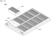
- FIG. 12 is a perspective view of a pack case 1000 included in a battery pack in which a cell stack assembly 100 according to a first embodiment of the present disclosure is accommodated.
- the pack case 1000 includes a base plate 1100 and a side wall 1200. Specifically, the pack case 1000 includes a base plate 1100 supporting a lower portion of the cell stack assembly 100 as shown in FIG. 12 , and a side wall 1200 coupling to a rim of the base plate 1100 to support a lateral portion of the cell stack assembly 100.
- the pack case 1000 further includes a plurality of separation walls 1300 coupled to the base plate 1100 to provide separation between a pair of neighboring cell stack assemblies 100.
- the separation walls 1300 have the purpose of providing separation between each cell stack assembly 100 and blocking the movement of heat.
- the battery pack Since the battery pack has a separating member 140 applied to each of the accommodated cell stack assemblies 100, the battery pack has the effect of delaying the transfer of heat (H) to the entire cell stack assembly 100 in case of a thermal runaway phenomenon in any one of the cell stack assemblies 100.
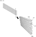
- FIG. 13 and FIG. 14 are cross-sectional perspective views of a separating member 140 included in the cell stack assembly 100 according to a second embodiment.
- the thickness of the first supporting part 140a, the second supporting part 140b, the third supporting part, and the fourth supporting part becomes thicker towards the edges and thinner towards the center; in other words, the thickness of the first to fourth supporting parts connecting both sides of the separating member 140 including the protrusion part 141 is thinner than the thickness of the first to fourth supporting parts of the separating member 140 of the cell stack assembly 100 according to the first embodiment. Accordingly, the movement of heat H through the first to fourth supporting parts may be limited, and in particular, the amount of heat H that moves through conduction may be significantly reduced.
- FIG. 15 is an enlarged view of the top ( FIG. 15(a) ) and bottom ( FIG. 15(b) ) of the separating member 140 of FIG. 13 , respectively.
- Heat H transferred to one side of the separating member 140 moves in the form of conduction to the other side through the first supporting part 140a corresponding to the top and the second supporting part 140b corresponding to the bottom of the separating member 140, as shown in FIG. 15 .
- the third supporting part and the fourth supporting part also become the only conduction pathways for the heat H to move in the same manner as the first supporting part 140a and the second supporting part 140b.
- the amount of heat H that moves may be reduced.
- FIG. 16 is a perspective view of a cell stack assembly 100 according to a third embodiment of the present disclosure.
- the cell stack assembly 100 includes a cell stack 110 and a separating member 140. More specifically, the cell stack assembly 100 includes a cell stack 110 stacked in one direction with a plurality of battery cells 111 having electrode leads (not shown) derived from one or both sides as shown in FIG. 16 , and a busbar 121 in electrical connection with each electrode lead of the cell stack 110, a busbar frame 120 coupled to each of the front and rear surfaces of the cell stack 110, an end plate 130 coupled to the busbar frame 120 to cover the busbar 121, and a separating member 140 configured to contact a first surface of the outermost cell 111 on each side of the cell stack 110.
- the cell stack assembly 100 of the present disclosure may be a structure in which the inner cells 111 and separating members 140 are exposed to the outside, as shown in FIG. 16 , but may also be a structure in which the cells 111 and separating members 140 are sealed and not exposed to the outside.
- the separating member 140 is configured to contact the outer surface of the outermost cell 111 on both sides of the cell stack 110, as shown in FIG. 16 . At this time, the separating members 140 may be coupled to and fixed to the busbar frame 120.
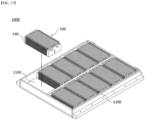
- FIG. 17 is a perspective view of a pack case 1000 included in a battery pack in which a cell stack assembly 100 according to a third embodiment of the present disclosure is accommodated.
- the pack case 1000 includes a base plate 1100 and a side wall 1200. Specifically, the pack case 1000 includes a base plate 1100 supporting a lower portion of the cell stack assembly 100 as shown in FIG. 17 , and a side wall 1200 coupling to a rim of the base plate 1100 to support a lateral portion of the cell stack assembly 100.
- each pair of neighboring cell stacks 110 has a separating member 140 provided on both sides of each cell stack 110, in other words, there are two separating members 140 between the pair of cell stacks 110.
- the separating members 140 provide separation between each cell stack 110 and prevent heat H from being transferred from one cell stack 110 to the other neighboring cell stack 110.
- the battery pack Since the battery pack has the separating member 140 applied to each of the cell stack assemblies 100 accommodated, the battery pack has the effect of delaying the transfer of heat (H) to the entire cell stack assembly 100 in the case of a thermal runaway phenomenon in any one of the cell stack assemblies 100.
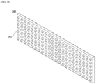
- FIG. 18 is a perspective view of a separating member 140 included in a cell stack assembly 100 according to a fourth embodiment of the present disclosure.
- the separating member 140 of the present disclosure may be formed to have a protrusion part 141 having various patterns, such as a dot pattern as shown in FIG. 18 .
- FIG. 19 is a perspective view of a separating member 140 included in a cell stack assembly 100 according to a fifth embodiment of the present disclosure.
- the separating member 140 of the present disclosure may be formed to have protrusion parts 141 having various patterns, such as a grid pattern as shown in FIG. 19 .
- FIG. 20 is a perspective view of a separating member 140 included in a cell stack assembly 100 according to a sixth embodiment of the present disclosure.
- the separating member 140 of the present disclosure may be formed to have protrusion parts 141 having various patterns, such as a striped pattern as shown in FIG. 20 .
- the protrusion parts 141 are formed to extend along the height direction of the separating member 140 and to be spaced apart at predetermined intervals along the length direction of the separating member 140.
- FIG. 21 is a perspective view of a separating member 140 included in a cell stack assembly 100 according to a seventh embodiment of the present disclosure.
- the separating member 140 of the present disclosure may be formed to have protrusion parts 141 having various patterns, such as a striped pattern as shown in FIG. 21 .
- the protrusion parts 141 are formed to extend along the length direction of the separating member 140 and to be spaced apart at predetermined intervals along the height direction of the separating member 140.
Landscapes
- Chemical & Material Sciences (AREA)
- Chemical Kinetics & Catalysis (AREA)
- Electrochemistry (AREA)
- General Chemical & Material Sciences (AREA)
- Engineering & Computer Science (AREA)
- Manufacturing & Machinery (AREA)
- Battery Mounting, Suspending (AREA)
- Secondary Cells (AREA)
Abstract
Description
- The present application is a national phase entry under of International Application No. , filed on , which claims priority from
Korean Patent Application No. 10-2023-0016354, filed on February 07, 2023 - The present disclosure relates to a cell stack assembly and a battery pack including the same. The cell stack assembly of the present disclosure includes a separating member including a hollow interior and a protrusion part on each of both sides. The battery pack of the present disclosure, including the cell stack assembly, is further characterized in that the separating members applied to each cell stack assembly inhibit the movement of heat in various forms.
- The types of secondary batteries that are currently widely used include lithium-ion batteries, lithium polymer batteries, nickel-cadmium batteries, nickel-hydrogen batteries, nickel-zinc batteries, etc. The operating voltage of such unit secondary battery cells, in other words, unit battery cells, is about 2.5V to 4.5V. Therefore, if a higher output voltage than this is required, a plurality of such battery cells may be connected in series to form a battery pack. In addition, a battery pack may be configured by connecting a plurality of battery cells in parallel according to a charge and discharge capacity required for the battery pack. Accordingly, the number of battery cells included in the battery pack may be varied depending on the required output voltage or charge and discharge capacity.
- When constructing a battery pack by connecting a plurality of battery cells in series/parallel, it is general to first construct a battery module comprising at least one battery cell, and to construct a battery pack by adding other components using such at least one battery module.
- A conventional battery module generally includes at least one cell stack comprising battery cells and a housing structure made of a metal material in a box form accommodating such at least one cell stack, in other words, a module frame, etc.
- Further, in order to solve the problem that the energy density of the entire battery pack is reduced due to the weight or volume, and the like of the module frame itself, and the weight of the entire battery pack is increased, a cell stack assembly excluding the module frame composition that wraps and protects the cell stack is utilized as a substitute for the conventional battery module.
-
FIG. 1 is a perspective view of a conventionalcell stack assembly 60, excluding the module frame composition. Referring toFIG. 1 , a plurality ofbattery cells 10 are stacked in a row to form acell stack 20 and coupled to the front and rear surfaces of thecell stack 20 is abusbar frame 30 that includes busbars that connect to electrode leads of each cell. There also shown is anend plate 40 coupling with thebusbar frame 30 for protecting the electrode leads and busbars. -
FIG. 2 provides a supportingbeam 50 for supporting and protecting the cell stacks 20 in thecell stack assembly 60 ofFIG. 1 . Referring toFIG. 2 , the supportingbeams 50 are configured to support eachcell stack 20 on both sides of thecell stack 20 while simultaneously protecting it from external impact. -
FIG. 3 illustrates apack case 70 included in a conventional battery pack in which thecell stack assembly 60 ofFIG. 2 is accommodated. - When a
cell stack assembly 60 included with a supportingbeam 50 is accommodated in apack case 70 of the same structure as shown inFIG. 3 , the supportingbeam 50 may sufficiently serve to separate and protect a neighboring pair ofcell stacks 20. - However, the supporting
beam 50 of eachcell stack assembly 60 is in good heat transfer with the supportingbeam 50 of the other neighboringcell stack assembly 60, such that if a thermal runaway occurs in onecell stack 20, there is no way to prevent the transfer of high temperature heat to theother cell stack 20. - Moreover, because each cell included within the
cell stack assembly 60 is stacked under pressure in contact with each other to form asingle cell stack 20, there is no way to prevent the transfer of high temperature heat to the other cells if a thermal runaway occurs in any one cell within thecell stack assembly 60. - Therefore, it is an object of the present disclosure to provide a cell stack assembly having a structure capable of suppressing the movement of heat in various forms, and a battery pack including the same.
- Further, it is an object of the present disclosure to provide a cell stack assembly and a battery pack comprising the same which is lightweight while applying a separating member which suppresses the movement of heat.
- Other objects and advantages of the present disclosure will be understood from the following description, which will become more apparent from the embodiments of the present disclosure, and it will be easily understood that the objects and advantages of the present disclosure may be realized by the means and combinations thereof disclosed in the claims of the patent.
- According to the present disclosure, provide a cell stack assembly comprising: a cell stack having a plurality of battery cells stacked with electrode leads derived from one or both sides; and a separating member configured to contact a first side surface of at least one battery cell of the cell stack, wherein the separating member comprising a hollow part therein and a protrusion part on each of both side surfaces.
- At least one of the outer and inner surfaces of the separating member may be coated with a metal thin film.
- The protrusion parts may comprise a pattern of any one of a dot pattern, a stripe pattern, a grid pattern, and a honeycomb pattern.
- The separating member may comprise a first supporting part and a second supporting part connecting the top and bottom of both side surfaces comprising the protrusion part, respectively, wherein the thickness of the first supporting part and the second supporting part may increase towards the edges.
- The separating member may comprise a material of any one of glass and stainless steel.
- The separating members may be attached to both side surfaces of the cell stack, respectively.
- According to the present disclosure, provide a battery pack comprising a pack case accommodating the cell stack assembly, wherein the pack case includes: a base plate supporting a lower portion of the cell stack assembly; and side walls coupling to a rim of the base plate to support lateral portions of the cell stack assembly.
- At least one of the outer surface and the inner surface of the separating member may be coated with a metal thin film.
- The protrusion part may comprise a pattern of any one of a dot pattern, a stripe pattern, a grid pattern, and a honeycomb pattern.
- The separating member may comprise a first supporting part and a second supporting part connecting the top and bottom of both side surfaces comprising the protrusion part, respectively, wherein the thickness of the first supporting part and the second supporting part may increase towards the edges.
- The separating member may comprise a material of any one of glass and stainless steel.
- At least one of the outer surface and the inner surface of the separating member may be coated with a metal thin film.
- The separating member may be attached to each of both sides of the cell stack.
- The pack case may further include a separation wall coupling with the base plate to be interposed between each of the cell stack assemblies such that any pair of neighboring disposed cell stack assemblies are separated.
- According to the present disclosure, the heat safety of cell stack assembly and battery pack can be improved.
- Further, according to the present disclosure, the cell stack assembly and battery pack can be lightweight to improve energy density.
-
-
FIG. 1 illustrates a conventional cell stack assembly. -
FIG. 2 illustrates a conventional cell stack assembly provided with a supporting beam. -
FIG. 3 illustrates a conventional battery pack. -
FIG. 4 is a perspective view of a cell stack assembly according to a first embodiment of the present disclosure. -
FIG. 5 illustrates another embodiment of a cell stack assembly applied with a module frame wrapping around the cell stack. -
FIG. 6 is a perspective view of a separating member included in a cell stack assembly according to a first embodiment of the present disclosure. -
FIG. 7 is a longitudinal perspective view ofFIG. 6 . -
FIG. 8 is a cross-sectional perspective view ofFIG. 6 . -
FIG. 9 is an enlarged view of the top and bottom of the separating member ofFIG. 7 , respectively. -
FIG. 10 illustrates heat transferred through a separating member in which a metal thin film is coated on an outer surface. -
FIG. 11 illustrates heat transferred through a separating member in which a metal thin film is coated on an inner surface. -
FIG. 12 is a perspective view of a pack case included in a battery pack in which a cell stack assembly according to a first embodiment of the present disclosure is accommodated. -
FIG. 13 is a longitudinal perspective view of a separating member included in a cell stack assembly according to a second embodiment of the present disclosure. -
FIG. 14 is a cross-sectional perspective view of a separating member included in a cell stack assembly according to a second embodiment of the present disclosure. -
FIG. 15 is an enlarged view of the top and bottom of the separating member ofFIG. 13 , respectively. -
FIG. 16 is a perspective view of a cell stack assembly according to a third embodiment of the present disclosure. -
FIG. 17 is a perspective view of a pack case included in a battery pack in which a cell stack assembly according to a third embodiment of the present disclosure is accommodated. -
FIG. 18 is a perspective view of a separating member included in a cell stack assembly according to a fourth embodiment of the present disclosure. -
FIG. 19 is a perspective view of a separating member included in a cell stack assembly according to a fifth embodiment of the present disclosure. -
FIG. 20 is a perspective view of a separating member included in a cell stack assembly according to a sixth embodiment of the present disclosure. -
FIG. 21 is a perspective view of a separating member included in a cell stack assembly according to a seventh embodiment of the present disclosure. - The present disclosure will now be described in detail with reference to the accompanying drawings, which illustrate preferred embodiments of the present disclosure. It is hereby understood that the terms and words used in this specification and claims are not to be construed in their ordinary or dictionary sense, but are to be interpreted with a meaning and concept consistent with the technical idea of the present disclosure, based on the principle that the inventor may define the concept of a term as he or she considers appropriate to best describe the disclosure.
- However, it should be understood that the present disclosure is not limited to the specific embodiments, and includes all modifications, equivalents, or alternatives within the spirit and technical scope of the present disclosure.
- In addition, in describing the present disclosure, specific descriptions of related disclosed configurations or functions are omitted where it is considered that such detailed description would obscure the subject matter of the present disclosure.
- The present disclosure is shown in embodiment to more fully explain the present disclosure to those of ordinary skill in the art, and therefore, the shapes and sizes of the components in the drawings may be exaggerated, omitted, or shown schematically for clarity. Accordingly, the size or proportions of each component are not necessarily indicative of its actual size or proportions.
- The present disclosure relates to a
cell stack assembly 100 and a battery pack comprising the same. Thecell stack assembly 100 of the present disclosure includes a separatingmember 140 that includes a hollow inside and includes aprotrusion part 141 on each of both side surfaces. The battery pack of the present disclosure including thecell stack assembly 100 is further characterized in that the movement of heat H in various forms is inhibited using the separatingmember 140 applied to eachcell stack assembly 100. -
FIGS. 4 to FIG. 12 relate to acell stack assembly 100 and a battery pack comprising the same according to a first embodiment of the present disclosure,FIGS. 13 to FIG. 15 relate to acell stack assembly 100 according to a second embodiment,FIGS. 16 to FIG. 17 relate to acell stack assembly 100 and a battery pack comprising the same according to a third embodiment of the present disclosure, andFIGS. 18 to FIG. 21 relate to acell stack assembly 100 according to a fourth to seventh embodiment of the present disclosure, respectively. - Hereinafter, with reference to each of these drawings, a
cell stack assembly 100 and a battery pack according to various embodiments of the present disclosure will be described. -
FIG. 4 is a perspective view of acell stack assembly 100 according to a first embodiment of the present disclosure. - The
cell stack assembly 100 includes acell stack 110 and a separatingmember 140. More specifically, thecell stack assembly 100 includes acell stack 110 stacked in one direction with a plurality ofbattery cells 111 having electrode leads (not shown) derived from one or both sides as shown inFIG. 4 , and abusbar 121 in electrically coupling with each electrode lead of thecell stack 110, abusbar frame 120 coupled to each front and rear surfaces of thecell stack 110, anend plate 130 coupled to thebusbar frame 120 to cover thebusbar 121, and a separatingmember 140 configured to contact one side of at least onebattery cell 111 of thecell stack 110. - The
cell stack assembly 100 of the present disclosure may be a structure in which theinner cells 111 and separatingmembers 140 are exposed to the outside, as shown inFIG. 4 , but may also be a structure in which thecells 111 and separatingmembers 140 are sealed and not exposed to the outside. -
FIG. 5 illustrates acell stack assembly 100 according to another embodiment of the present disclosure applied with amodule frame 150 surrounding thecell stack 110. - The
module frame 150 wraps around and covers the perimeter of thecell stack 110, and eachcell 111 is protected from the outside by coupling to themodule frame 150 orend plate 130. - The separating
members 140 are interposed between any one of the pair ofcells 111 among the plurality ofcells 111 included in thecell stack 110, as shown inFIG. 4 . - The separating
members 140 interposed between thecells 111 as described above serve to block the movement of heat H from cell to cell by separating between thecells 111. In other words, the separatingmembers 140 serve to prevent the transfer of the heat H to other neighboringcells 111 when one of thecells 111 undergoes a thermal runaway and emits high temperatures of heat H. -
FIG. 6 is a perspective view of a separatingmember 140 included in thecell stack assembly 100 according to a first embodiment of the present disclosure. - The separating
member 140 may be glass, which has a low thermal conductivity, or stainless steel, but any material may be used if it is safe for high heat H. - The separating
member 140 of the present disclosure is characterized in that it effectively blocks the movement of heat H by various means, including conduction, convection, and radiation. - The separating
member 140 includesprotrusion parts 141 projecting in a certain pattern on both sides, as shown inFIG. 6 . - The
protrusion parts 141 have the effect of reducing the area in contact with thecell 111, thereby reducing the path for heat H to be transferred from thecell 111 to the separatingmember 140. - The separating
member 140 also improves structural stability as theprotrusion part 141 has a stable pattern form. -
Fig. 7 andFig. 8 are cross-sectional perspective views of the separatingmember 140 ofFIG. 6 . - Specifically,
FIG. 7 is a cross-sectional view of A-A" ofFIG. 6 , andFIG. 8 is a cross-sectional view of B-B" ofFIG. 6 . - The separating
member 140 is a hollow structure that is hollow inside as shown inFIG. 7 andFIG. 8 . In other words, the separatingmember 140 includes ahollow part 142 inside. - The
hollow part 142 of the separatingmember 140 is maintained in a vacuum. - Because of the
hollow part 142 and the vacuum structure of thehollow part 142, the separatingmember 140 effectively blocks the movement of heat H in the form of conduction and convection inside the separatingmember 140. - The separating
member 140 includes a first supportingpart 140a and a second supportingpart 140b connecting the top and bottom of the two side surfaces including theprotrusion part 141, respectively, and a third supporting part and a fourth supporting part connecting the lateral portions of the two side surfaces, respectively. -
FIG. 9 is an enlarged view of the top (FIG. 9(a) ) and bottom (FIG. 9(b) ), respectively, of the separatingmember 140 ofFIG. 7 above. - Heat H transferred to one side of the separating
member 140 moves in the form of conduction to the other side through the first supportingpart 140a corresponding to the top and the second supportingpart 140b corresponding to the bottom of the separatingmember 140, as shown inFIG. 9 . Although not shown, the third supporting part and the fourth supporting part also become the only conduction pathways for heat H to move in the same manner as the first supportingpart 140a and the second supportingpart 140b. - The outer surface of said separating
member 140 may be coated with a metal thin film capable of reflecting the radiant heat H. In other words, the metal thin film reflects the heat H moving in the form of radiation so that only a portion of the heat H is transferred to the separatingmember 140. -
FIG. 10 schematically illustrates the transfer of heat (H) through a separatingmember 140 having a metal thin film coated on its outer surface. - According to
FIG. 10 , it can be noticed that the heat H moving toward the separatingmember 140 in the form of radiation is partially reflected from the surface of the separatingmember 140 and partially absorbed by the separatingmember 140. - The metal thin film may be coated not only on the outer surface of the separating
member 140, but also on the inner surface where thehollow part 142 is located. -
FIG. 11 schematically illustrates the transfer of heat (H) through a separating member (140) having a metal thin film coated on its inner surface. - According to
FIG. 11 , it can be noticed that the heat H moving in the form of radiation toward the separatingmember 140 is absorbed by the surface of the separatingmember 140, and the heat H radiating through thehollow part 142 is partially reflected through the metal thin film coated on the inner surface. -
FIG. 12 is a perspective view of apack case 1000 included in a battery pack in which acell stack assembly 100 according to a first embodiment of the present disclosure is accommodated. - The
pack case 1000 includes abase plate 1100 and aside wall 1200. Specifically, thepack case 1000 includes abase plate 1100 supporting a lower portion of thecell stack assembly 100 as shown inFIG. 12 , and aside wall 1200 coupling to a rim of thebase plate 1100 to support a lateral portion of thecell stack assembly 100. - The
pack case 1000 further includes a plurality ofseparation walls 1300 coupled to thebase plate 1100 to provide separation between a pair of neighboringcell stack assemblies 100. - The
separation walls 1300 have the purpose of providing separation between eachcell stack assembly 100 and blocking the movement of heat. - Since the battery pack has a separating
member 140 applied to each of the accommodatedcell stack assemblies 100, the battery pack has the effect of delaying the transfer of heat (H) to the entirecell stack assembly 100 in case of a thermal runaway phenomenon in any one of thecell stack assemblies 100. -
FIG. 13 andFIG. 14 are cross-sectional perspective views of a separatingmember 140 included in thecell stack assembly 100 according to a second embodiment. - In the separating
member 140, the thickness of the first supportingpart 140a, the second supportingpart 140b, the third supporting part, and the fourth supporting part becomes thicker towards the edges and thinner towards the center; in other words, the thickness of the first to fourth supporting parts connecting both sides of the separatingmember 140 including theprotrusion part 141 is thinner than the thickness of the first to fourth supporting parts of the separatingmember 140 of thecell stack assembly 100 according to the first embodiment. Accordingly, the movement of heat H through the first to fourth supporting parts may be limited, and in particular, the amount of heat H that moves through conduction may be significantly reduced. -
FIG. 15 is an enlarged view of the top (FIG. 15(a) ) and bottom (FIG. 15(b) ) of the separatingmember 140 ofFIG. 13 , respectively. - Heat H transferred to one side of the separating
member 140 moves in the form of conduction to the other side through the first supportingpart 140a corresponding to the top and the second supportingpart 140b corresponding to the bottom of the separatingmember 140, as shown inFIG. 15 . Although not shown, the third supporting part and the fourth supporting part also become the only conduction pathways for the heat H to move in the same manner as the first supportingpart 140a and the second supportingpart 140b. - However, since the thickness of the first supporting
part 140a and the second supportingpart 140b connecting both sides of the separatingmember 140 as shown inFIG. 15 is reduced, the amount of heat H that moves may be reduced. -
FIG. 16 is a perspective view of acell stack assembly 100 according to a third embodiment of the present disclosure. - The
cell stack assembly 100 includes acell stack 110 and a separatingmember 140. More specifically, thecell stack assembly 100 includes acell stack 110 stacked in one direction with a plurality ofbattery cells 111 having electrode leads (not shown) derived from one or both sides as shown inFIG. 16 , and abusbar 121 in electrical connection with each electrode lead of thecell stack 110, abusbar frame 120 coupled to each of the front and rear surfaces of thecell stack 110, anend plate 130 coupled to thebusbar frame 120 to cover thebusbar 121, and a separatingmember 140 configured to contact a first surface of theoutermost cell 111 on each side of thecell stack 110. - The
cell stack assembly 100 of the present disclosure may be a structure in which theinner cells 111 and separatingmembers 140 are exposed to the outside, as shown inFIG. 16 , but may also be a structure in which thecells 111 and separatingmembers 140 are sealed and not exposed to the outside. - The separating
member 140 is configured to contact the outer surface of theoutermost cell 111 on both sides of thecell stack 110, as shown inFIG. 16 . At this time, the separatingmembers 140 may be coupled to and fixed to thebusbar frame 120. - As described above, the separating
member 140 attached to theoutermost cell 111 of thecell stack 110 serves to support both sides of thecell stack 110, and also serves to block the heat H inside thecell stack 110 from being released to the outside. In other words, when thecell stack 110 overheats and releases high temperature heat H, the separatingmember 140 serves to prevent the heat H from being transferred to other neighboring cell stacks 110. -
FIG. 17 is a perspective view of apack case 1000 included in a battery pack in which acell stack assembly 100 according to a third embodiment of the present disclosure is accommodated. - The
pack case 1000 includes abase plate 1100 and aside wall 1200. Specifically, thepack case 1000 includes abase plate 1100 supporting a lower portion of thecell stack assembly 100 as shown inFIG. 17 , and aside wall 1200 coupling to a rim of thebase plate 1100 to support a lateral portion of thecell stack assembly 100. - In the
pack case 1000, each pair of neighboring cell stacks 110 has a separatingmember 140 provided on both sides of eachcell stack 110, in other words, there are two separatingmembers 140 between the pair of cell stacks 110. - The separating
members 140 provide separation between eachcell stack 110 and prevent heat H from being transferred from onecell stack 110 to the other neighboringcell stack 110. - Since the battery pack has the separating
member 140 applied to each of thecell stack assemblies 100 accommodated, the battery pack has the effect of delaying the transfer of heat (H) to the entirecell stack assembly 100 in the case of a thermal runaway phenomenon in any one of thecell stack assemblies 100. -
FIG. 18 is a perspective view of a separatingmember 140 included in acell stack assembly 100 according to a fourth embodiment of the present disclosure. - The separating
member 140 of the present disclosure may be formed to have aprotrusion part 141 having various patterns, such as a dot pattern as shown inFIG. 18 . -
FIG. 19 is a perspective view of a separatingmember 140 included in acell stack assembly 100 according to a fifth embodiment of the present disclosure. - The separating
member 140 of the present disclosure may be formed to haveprotrusion parts 141 having various patterns, such as a grid pattern as shown inFIG. 19 . -
FIG. 20 is a perspective view of a separatingmember 140 included in acell stack assembly 100 according to a sixth embodiment of the present disclosure. - The separating
member 140 of the present disclosure may be formed to haveprotrusion parts 141 having various patterns, such as a striped pattern as shown inFIG. 20 . In this case, theprotrusion parts 141 are formed to extend along the height direction of the separatingmember 140 and to be spaced apart at predetermined intervals along the length direction of the separatingmember 140. -
FIG. 21 is a perspective view of a separatingmember 140 included in acell stack assembly 100 according to a seventh embodiment of the present disclosure. - The separating
member 140 of the present disclosure may be formed to haveprotrusion parts 141 having various patterns, such as a striped pattern as shown inFIG. 21 . In this case, theprotrusion parts 141 are formed to extend along the length direction of the separatingmember 140 and to be spaced apart at predetermined intervals along the height direction of the separatingmember 140. - As above, the present invention has been described in more detail through the drawings and embodiments. However, since the configuration described in the drawings or embodiments described herein is merely one embodiment of the present invention and do not represent the overall technical spirit of the invention, it should be understood that the invention covers various equivalents, modifications, and substitutions at the time of filing of this application.
-
- 10: (conventional art) battery cell
- 20: (conventional art) cell stack
- 30: (conventional art) busbar frame
- 40: (conventional art) end plate
- 50: (conventional art) supporting beam
- 60: (conventional art) cell stack assembly
- 70: (conventional art) pack case
- 100: cell stack assembly
- 110: cell stack
- 111: cell
- 120: busbar frame
- 121: busbar
- 130: end plate
- 140: separating member
- 140a: first supporting part
- 140b: second supporting part
- 141: protrusion part
- 142: hollow part
- 150: module frame
- 1000: pack case
- 1100: base plate
- 1200: side wall
- 1300: separation wall
- H: heat
Claims (14)
- A cell stack assembly, comprising:a cell stack having a plurality of battery cells stacked with electrode leads derived from one or both sides; anda separating member configured to contact a first side surface of at least one battery cell of the cell stack,wherein the separating member comprising a hollow part therein and a protrusion part on each of both side surfaces.
- The cell stack assembly of claim 1, wherein at least one of the outer and inner surfaces of the separating member are coated with a metal thin film.
- The cell stack assembly of claim 1, wherein the protrusion parts comprise a pattern of any one of a dot pattern, a stripe pattern, a grid pattern, and a honeycomb pattern.
- The cell stack assembly of claim 1, wherein the separating member comprises a first supporting part and a second supporting part connecting the top and bottom of both side surfaces comprising the protrusion part, respectively,
wherein the thickness of the first supporting part and the second supporting part may increases the edges. - The cell stack assembly of claim 1, wherein the separating member comprises a material of any one of glass and stainless steel.
- The cell stack assembly of claim 1, wherein the separating members is attached to both side surfaces of the cell stack, respectively.
- A battery pack, comprising:a pack case accommodating the cell stack assembly of claim 1,wherein the pack case, comprising:a base plate supporting a lower portion of the cell stack assembly; andside walls coupling to a rim of the base plate to support lateral portions of the cell stack assembly.
- A battery pack of claim 7, wherein at least one of the outer surface and the inner surface of the separating member are coated with a metal thin film.
- A battery pack of claim 7, wherein the protrusion part comprises a pattern of any one of a dot pattern, a stripe pattern, a grid pattern, and a honeycomb pattern.
- A battery pack of claim 7, wherein the separating member comprises a first supporting part and a second supporting part connecting the top and bottom of both side surfaces comprising the protrusion part, respectively,
wherein the thickness of the first supporting part and the second supporting part increases towards the edges. - A battery pack of claim 7, wherein the separating member comprises a material of any one of glass and stainless steel.
- A battery pack of claim 7, wherein at least one of the outer surface and the inner surface of the separating member are coated with a metal thin film.
- A battery pack of claim 7, wherein the separating member is attached to each of both sides of the cell stack.
- A battery pack of claim 7, wherein the pack case further comprises a separation wall coupling with the base plate to be interposed between each of the cell stack assemblies such that any pair of neighboring disposed cell stack assemblies are separated.
Applications Claiming Priority (2)
| Application Number | Priority Date | Filing Date | Title |
|---|---|---|---|
| KR1020230016354A KR20240123671A (en) | 2023-02-07 | 2023-02-07 | Cell stack assembly and battery pack including the same |
| PCT/KR2024/001634 WO2024167239A1 (en) | 2023-02-07 | 2024-02-05 | Cell stack assembly and battery pack comprising same |
Publications (2)
| Publication Number | Publication Date |
|---|---|
| EP4571981A1 true EP4571981A1 (en) | 2025-06-18 |
| EP4571981A4 EP4571981A4 (en) | 2026-03-11 |
Family
ID=92262892
Family Applications (1)
| Application Number | Title | Priority Date | Filing Date |
|---|---|---|---|
| EP24753568.5A Pending EP4571981A4 (en) | 2023-02-07 | 2024-02-05 | CELL STACK ARRANGEMENT AND BATTERY PACK SO THAT |
Country Status (6)
| Country | Link |
|---|---|
| US (1) | US20260100469A1 (en) |
| EP (1) | EP4571981A4 (en) |
| JP (1) | JP2025530392A (en) |
| KR (1) | KR20240123671A (en) |
| CN (1) | CN119923747A (en) |
| WO (1) | WO2024167239A1 (en) |
Family Cites Families (12)
| Publication number | Priority date | Publication date | Assignee | Title |
|---|---|---|---|---|
| KR100627335B1 (en) * | 2004-06-25 | 2006-09-25 | 삼성에스디아이 주식회사 | Battery Modules and Battery Modules |
| KR100684766B1 (en) * | 2005-07-29 | 2007-02-20 | 삼성에스디아이 주식회사 | Secondary battery module |
| KR101182958B1 (en) * | 2010-02-01 | 2012-09-18 | 에스비리모티브 주식회사 | Secondary battery module |
| KR102024326B1 (en) * | 2015-10-14 | 2019-09-23 | 주식회사 엘지화학 | Battery module and battery pack comprising the smae |
| JP6726478B2 (en) * | 2016-02-19 | 2020-07-22 | 株式会社Gsユアサ | Power storage device, method of manufacturing power storage device, and method of manufacturing adjacent member for power storage device |
| CN111373600B (en) * | 2018-02-27 | 2023-11-03 | 松下知识产权经营株式会社 | battery module |
| DE102019130497A1 (en) * | 2019-11-12 | 2021-05-12 | Audi Ag | Separating device for a battery module, battery module and motor vehicle |
| KR102910004B1 (en) * | 2020-05-08 | 2026-01-08 | 에스케이온 주식회사 | Battery module |
| KR102802106B1 (en) | 2020-07-28 | 2025-05-02 | 에스케이온 주식회사 | Battery pack |
| KR102869313B1 (en) * | 2020-08-20 | 2025-10-13 | 주식회사 엘지에너지솔루션 | Battery module including heat insulating member |
| JP7488202B2 (en) * | 2021-01-18 | 2024-05-21 | イビデン株式会社 | Heat transfer suppression sheet for battery pack and battery pack |
| KR20230016354A (en) | 2021-07-26 | 2023-02-02 | 현대모비스 주식회사 | Automatic Analysis System for Quality Data Based on Machine Learning |
-
2023
- 2023-02-07 KR KR1020230016354A patent/KR20240123671A/en active Pending
-
2024
- 2024-02-05 JP JP2025515891A patent/JP2025530392A/en active Pending
- 2024-02-05 US US19/113,801 patent/US20260100469A1/en active Pending
- 2024-02-05 EP EP24753568.5A patent/EP4571981A4/en active Pending
- 2024-02-05 CN CN202480004094.1A patent/CN119923747A/en active Pending
- 2024-02-05 WO PCT/KR2024/001634 patent/WO2024167239A1/en not_active Ceased
Also Published As
| Publication number | Publication date |
|---|---|
| WO2024167239A1 (en) | 2024-08-15 |
| JP2025530392A (en) | 2025-09-11 |
| US20260100469A1 (en) | 2026-04-09 |
| KR20240123671A (en) | 2024-08-14 |
| CN119923747A (en) | 2025-05-02 |
| EP4571981A4 (en) | 2026-03-11 |
Similar Documents
| Publication | Publication Date | Title |
|---|---|---|
| KR102858412B1 (en) | Battery pack and manufacturing method thereof | |
| EP1901365B1 (en) | Battery cell with small groove at surface and battery pack including the same | |
| KR102880677B1 (en) | Battery module and, battery pack and vehicle including same | |
| EP4175041B1 (en) | Battery module, battery pack, and vehicle | |
| US20240222781A1 (en) | Battery Module and Battery Pack Including the Same | |
| EP3961792A1 (en) | Battery module and battery pack including same | |
| KR102799774B1 (en) | Battery pack and vehicle including the same | |
| KR102826209B1 (en) | Battery Module Comprising Base Insulation Member | |
| KR20240012321A (en) | Battery pack and device inctuding the same | |
| US20240072401A1 (en) | Battery module and battery pack comprising same | |
| EP4571981A1 (en) | Cell stack assembly and battery pack comprising same | |
| EP4560793A1 (en) | Cell assembly and battery pack comprising same | |
| EP4372887B1 (en) | Battery pack and vehicle including the same | |
| EP4432446A1 (en) | Battery module and, battery pack comprising same and vehicle comprising same | |
| KR20240083794A (en) | battery module and battery pack including the same | |
| KR20240021694A (en) | Battery pack and vehicle including the same | |
| KR20250020103A (en) | Battery module and battery pack including the same | |
| KR20240012303A (en) | Battery cell assembly and battery pack including the same | |
| KR20230146306A (en) | Battery pack and vehicle including the same | |
| EP4571982A1 (en) | Battery pack | |
| EP4478508B1 (en) | Battery module and battery pack including same | |
| JP7818108B2 (en) | Pack case with improved heat dissipation structure | |
| KR102945209B1 (en) | Battery pack and energy storage device including the same | |
| EP4376198B1 (en) | Battery pack and device including the same | |
| EP4629359A1 (en) | Battery pack and energy storage device including same |
Legal Events
| Date | Code | Title | Description |
|---|---|---|---|
| STAA | Information on the status of an ep patent application or granted ep patent |
Free format text: STATUS: THE INTERNATIONAL PUBLICATION HAS BEEN MADE |
|
| PUAI | Public reference made under article 153(3) epc to a published international application that has entered the european phase |
Free format text: ORIGINAL CODE: 0009012 |
|
| STAA | Information on the status of an ep patent application or granted ep patent |
Free format text: STATUS: REQUEST FOR EXAMINATION WAS MADE |
|
| 17P | Request for examination filed |
Effective date: 20250311 |
|
| AK | Designated contracting states |
Kind code of ref document: A1 Designated state(s): AL AT BE BG CH CY CZ DE DK EE ES FI FR GB GR HR HU IE IS IT LI LT LU LV MC ME MK MT NL NO PL PT RO RS SE SI SK SM TR |
|
| A4 | Supplementary search report drawn up and despatched |
Effective date: 20260205 |
|
| RIC1 | Information provided on ipc code assigned before grant |
Ipc: H01M 50/289 20210101AFI20260130BHEP Ipc: H01M 10/60 20140101ALI20260130BHEP Ipc: H01M 10/658 20140101ALI20260130BHEP Ipc: H01M 50/204 20210101ALI20260130BHEP |