EP4571975A1 - Battery gripper - Google Patents
Battery gripper Download PDFInfo
- Publication number
- EP4571975A1 EP4571975A1 EP23900992.1A EP23900992A EP4571975A1 EP 4571975 A1 EP4571975 A1 EP 4571975A1 EP 23900992 A EP23900992 A EP 23900992A EP 4571975 A1 EP4571975 A1 EP 4571975A1
- Authority
- EP
- European Patent Office
- Prior art keywords
- battery
- magnet
- battery cell
- adapter
- magnet adapter
- Prior art date
- Legal status (The legal status is an assumption and is not a legal conclusion. Google has not performed a legal analysis and makes no representation as to the accuracy of the status listed.)
- Pending
Links
Images



Classifications
-
- H—ELECTRICITY
- H01—ELECTRIC ELEMENTS
- H01M—PROCESSES OR MEANS, e.g. BATTERIES, FOR THE DIRECT CONVERSION OF CHEMICAL ENERGY INTO ELECTRICAL ENERGY
- H01M50/00—Constructional details or processes of manufacture of the non-active parts of electrochemical cells other than fuel cells, e.g. hybrid cells
- H01M50/20—Mountings; Secondary casings or frames; Racks, modules or packs; Suspension devices; Shock absorbers; Transport or carrying devices; Holders
- H01M50/244—Secondary casings; Racks; Suspension devices; Carrying devices; Holders characterised by their mounting method
-
- H—ELECTRICITY
- H01—ELECTRIC ELEMENTS
- H01F—MAGNETS; INDUCTANCES; TRANSFORMERS; SELECTION OF MATERIALS FOR THEIR MAGNETIC PROPERTIES
- H01F7/00—Magnets
- H01F7/02—Permanent magnets [PM]
- H01F7/0231—Magnetic circuits with PM for power or force generation
- H01F7/0252—PM holding devices
- H01F7/0257—Lifting, pick-up magnetic objects
-
- B—PERFORMING OPERATIONS; TRANSPORTING
- B25—HAND TOOLS; PORTABLE POWER-DRIVEN TOOLS; MANIPULATORS
- B25J—MANIPULATORS; CHAMBERS PROVIDED WITH MANIPULATION DEVICES
- B25J15/00—Gripping heads and other end effectors
- B25J15/0033—Gripping heads and other end effectors with gripping surfaces having special shapes
- B25J15/0038—Cylindrical gripping surfaces
-
- B—PERFORMING OPERATIONS; TRANSPORTING
- B25—HAND TOOLS; PORTABLE POWER-DRIVEN TOOLS; MANIPULATORS
- B25J—MANIPULATORS; CHAMBERS PROVIDED WITH MANIPULATION DEVICES
- B25J15/00—Gripping heads and other end effectors
- B25J15/06—Gripping heads and other end effectors with vacuum or magnetic holding means
- B25J15/0608—Gripping heads and other end effectors with vacuum or magnetic holding means with magnetic holding means
-
- H—ELECTRICITY
- H01—ELECTRIC ELEMENTS
- H01F—MAGNETS; INDUCTANCES; TRANSFORMERS; SELECTION OF MATERIALS FOR THEIR MAGNETIC PROPERTIES
- H01F7/00—Magnets
- H01F7/02—Permanent magnets [PM]
- H01F7/0231—Magnetic circuits with PM for power or force generation
- H01F7/0242—Magnetic drives, magnetic coupling devices
-
- H—ELECTRICITY
- H01—ELECTRIC ELEMENTS
- H01M—PROCESSES OR MEANS, e.g. BATTERIES, FOR THE DIRECT CONVERSION OF CHEMICAL ENERGY INTO ELECTRICAL ENERGY
- H01M10/00—Secondary cells; Manufacture thereof
- H01M10/04—Construction or manufacture in general
- H01M10/0404—Machines for assembling batteries
-
- H—ELECTRICITY
- H01—ELECTRIC ELEMENTS
- H01M—PROCESSES OR MEANS, e.g. BATTERIES, FOR THE DIRECT CONVERSION OF CHEMICAL ENERGY INTO ELECTRICAL ENERGY
- H01M10/00—Secondary cells; Manufacture thereof
- H01M10/04—Construction or manufacture in general
- H01M10/0422—Cells or battery with cylindrical casing
-
- H—ELECTRICITY
- H01—ELECTRIC ELEMENTS
- H01M—PROCESSES OR MEANS, e.g. BATTERIES, FOR THE DIRECT CONVERSION OF CHEMICAL ENERGY INTO ELECTRICAL ENERGY
- H01M50/00—Constructional details or processes of manufacture of the non-active parts of electrochemical cells other than fuel cells, e.g. hybrid cells
- H01M50/10—Primary casings; Jackets or wrappings
- H01M50/102—Primary casings; Jackets or wrappings characterised by their shape or physical structure
- H01M50/107—Primary casings; Jackets or wrappings characterised by their shape or physical structure having curved cross-section, e.g. round or elliptic
-
- H—ELECTRICITY
- H01—ELECTRIC ELEMENTS
- H01M—PROCESSES OR MEANS, e.g. BATTERIES, FOR THE DIRECT CONVERSION OF CHEMICAL ENERGY INTO ELECTRICAL ENERGY
- H01M50/00—Constructional details or processes of manufacture of the non-active parts of electrochemical cells other than fuel cells, e.g. hybrid cells
- H01M50/50—Current conducting connections for cells or batteries
- H01M50/528—Fixed electrical connections, i.e. not intended for disconnection
-
- Y—GENERAL TAGGING OF NEW TECHNOLOGICAL DEVELOPMENTS; GENERAL TAGGING OF CROSS-SECTIONAL TECHNOLOGIES SPANNING OVER SEVERAL SECTIONS OF THE IPC; TECHNICAL SUBJECTS COVERED BY FORMER USPC CROSS-REFERENCE ART COLLECTIONS [XRACs] AND DIGESTS
- Y02—TECHNOLOGIES OR APPLICATIONS FOR MITIGATION OR ADAPTATION AGAINST CLIMATE CHANGE
- Y02E—REDUCTION OF GREENHOUSE GAS [GHG] EMISSIONS, RELATED TO ENERGY GENERATION, TRANSMISSION OR DISTRIBUTION
- Y02E60/00—Enabling technologies; Technologies with a potential or indirect contribution to GHG emissions mitigation
- Y02E60/10—Energy storage using batteries
Definitions
- the present disclosure relates to a battery gripper. More specifically, it relates to a fixing device for a cylindrical battery cell.
- Secondary batteries have high applicability according to product groups and electrical characteristics such as high energy density, and thus are commonly applied not only to portable devices but also to electric vehicles (EVs) or hybrid electric vehicles (HEVs) driven by electric power sources.
- EVs electric vehicles
- HEVs hybrid electric vehicles
- Such secondary batteries are attracting attention as a new energy source to improve eco-friendliness and energy efficiency in that it has not only a primary advantage of dramatically reducing the use of fossil fuels, but also no by-products generated from the use of energy.
- Secondary batteries widely used at present include lithium-ion batteries, lithium polymer batteries, nickel cadmium batteries, nickel hydrogen batteries, nickel zinc batteries, and the like.
- An operating voltage of the unit secondary battery cell namely a unit battery cell, is about 2.5 V to 4.5 V. Therefore, if a higher output voltage is required, a plurality of battery cells may be connected in series to configure a battery pack. In addition, depending on the charge/discharge capacity required for the battery pack, a plurality of battery cells may be connected in parallel to configure a battery pack. Thus, the number of battery cells included in the battery pack may be variously set according to the required output voltage or the demanded charge/discharge capacity.
- a battery gripper comprising: a side support supporting the side surface of a battery cell; at least one first magnet adapter provided in at least some areas of the side support; a first magnet embedded in the first magnet adapter and configured to face the battery cell; and a lower support supporting the lower surface of the battery cell.
- the first magnet adapter is configured to be detachable from the side support.
- the first magnet adapter is provided in plurality spaced apart from each other by a predetermined distance along the outer circumferential surface of the battery cell.
- the battery gripper comprises: a second magnet adapter provided in at least some areas of the lower support; and a second magnet embedded in the second magnet adapter and configured to face the battery cell.
- the second magnet adapter is configured to be detachable from the lower support.
- the second magnet adapter has a disk shape.
- the second magnet is provided along the circumferential direction of the second magnet adapter.
- the second magnet adapter is configured to be rotatable with respect to the central axis of the battery cell.
- the battery gripper comprises a motor connected to the second magnet adapter.
- the side support comprises: a first side support that comprises the first magnet adapter; and a second side support that does not comprise the first magnet adapter.
- the first side support is configured to be capable of: advancing toward the battery cell; and retreating from the battery cell.
- the second magnet adapter is configured to be capable of: advancing toward the battery cell; and retreating from the battery cell.
- the side support and the lower support comprise a resin material.
- welding quality can be improved.
- the conventional battery gripper had a general gripper form without a separate slip prevention function in the gripper at the battery handover rotary.
- a cylindrical battery After inserting an electrode assembly in the form of a jelly roll with a current collector plate CP welded into a battery can, alignment of the battery is required for welding the current collector plate CP and the beading portion BD of the battery can.
- welding and movement are performed while rotating in a rotary form due to the driving characteristics of the equipment, so that the rotation and slip phenomenon of the battery occurred in the existing general gripper type. That is, in the conventional battery fixing device, there was no mechanism or shape to prevent the battery from slipping in the gripper, thereby causing slippage. Accordingly, it became necessary to develop a gripper in a form where the rotation or slip of the battery does not occur in order to satisfy the quality of welding.
- the present inventor carefully examined the configuration for preventing rotation or slip when welding the beading portion BD of a cylindrical battery, and as a result, the battery gripper 1 of the present disclosure has been delivered, which will be described in detail below with reference to FIGS. 1 to 9 .
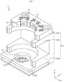
- FIG. 1 is a view for describing a battery gripper 1 according to an embodiment of the present disclosure
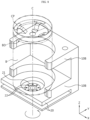
- FIG. 2 is a view for describing a state in which a battery is mounted on the battery gripper 1 of FIG. 1 .
- the battery gripper 1 includes a side support 10 and a lower support 20.
- the side support 10 may support the side surface of the battery cell B.
- the side support 10 may be configured to have a substantially arc shape to enable to support the side surface of the cylindrical battery cell B.
- the radius of the arc constituting the side support 10 may be greater than or equal to the radius of the cylindrical battery cell B. That is, in this structure, the side support 10 may be in the form of surrounding the side surface of the cylindrical battery cell B.
- the side support 10 may support at least some areas of the side surface of the battery cell B.
- the side support 10 may be provided in the form of a plurality of arc-shaped ribs.
- the side support 10 may also be provided in the form of a single arc-shaped rib.
- the side support 10 may also have a curved shape that entirely surrounds the side surface of the cylindrical battery cell B.
- At least one first magnet adapter 11 may be provided in at least some areas of the side support 10.
- the first magnet adapter 11 may be configured to face the battery cell B.
- the first magnet adapter 11 may have a first magnet 12 embedded therein.
- the first magnet 12 embedded in the first magnet adapter 11 may be configured to face the battery cell B.
- the first magnet 12 may be configured to face the battery cell B.
- the first magnet 12 may be embedded in a space within the first magnet adapter 11 and may be exposed toward the outside of the first magnet adapter 11 through a predetermined hole provided in the first magnet adapter 11.
- the side support 10 has some space recessed therein to accommodate the first magnet adapter 11, and the first magnet adapter 11 may be accommodated in the space.
- the magnet adapter may be fixed on the side support 10.
- the fixing method may be, for example, by screwing, but the coupling method is not limited thereto.
- the first magnet adapter 11 may also be removed from the side support. That is, the first magnet adapter 11 may be configured to be detachable from the side support 10.
- the first magnet adapter 11 may be provided in plurality spaced apart from each other by a predetermined distance along the outer circumferential surface of the battery cell B.
- the first magnet adapter 11 is provided in three along the side facing the battery cell B, but the embodiment of the present disclosure is not limited thereto.
- the first magnet adapter 11 may be provided in a single number or may be provided in a larger number than the embodiment of FIGS. 1 and 2 .
- the anti-slip effect of the battery cell B may be further improved.
- the magnitude of the attractive force acting between the first magnet adapter 11 and the battery cell B becomes stronger, and thus the anti-slip effect in the tangential direction of the battery cell B may be further improved.
- FIG. 3 is a cross-sectional view taken along line A-A' in FIG. 2 .
- the first magnet adapter 11 of the battery gripper 1 may be spaced apart from the battery cell B by a predetermined distance. That is, the first magnet adapter 11 may not be in direct contact with the battery cell B. Accordingly, the first magnet 12 embedded in the first magnet adapter 11 may also be spaced apart from the battery cell B by a predetermined distance. That is, the first magnet 12 may not be in direct contact with the battery cell B.
- the first magnet adapter 11 and/or the first magnet 12 by preventing direct contact of the first magnet adapter 11 and/or the first magnet 12 with the battery cell B, it is possible to prevent scratches from occurring on the battery can of the battery cell B. That is, since the first magnet 12 exerts magnetic force even without being in direct contact with the battery cell B, it does not necessarily have to be in contact with the battery cell B. Rather, it is preferable to be spaced apart from the battery cell B by a predetermined distance to prevent the occurrence of scratches. However, if the gap between the first magnet 12 and the battery cell B is too far, the strength of the magnetic force also weakens, and thus it is not preferable for the gap to become excessively large.
- the side support 10 and the lower support 20 may include a resin material.
- the side support 10 and the lower support 20 may include a plastic resin material.
- the side support 10 and the lower support 20 may include a polyether ether ketone (PEEK) material. Since the side support 10 and the lower support 20 are components in direct contact with the battery cell B, there is a high possibility of scratches occurring in the battery cell B if the side support 10 and the lower support 20 include a material with high hardness. Therefore, it is preferable to include a resin material that does not cause scratches while having a predetermined hardness. For example, since a polyether ether ketone (PEEK) material has a certain level of hardness and is also highly brittle, it can be applied to the side support 10 and the lower support 20 of the present disclosure.
- PEEK polyether ether ketone
- the first magnet adapter 11 may include a resin material.
- the first magnet adapter 11 may include a plastic resin material.
- the first magnet adapter 11 may include a polyether ether ketone (PEEK) material.
- the second magnet adapter 21 to be described later may also include a resin material.
- the second magnet adapter 21 may include a plastic resin material.
- the second magnet adapter 21 may include a polyether ether ketone (PEEK) material.
- the strength of the magnetic force may be adjusted without replacing the first magnet adapter 11 and/or the second magnet adapter 21.
- FIG. 4 is a view for describing a battery gripper 1 according to another embodiment of the present disclosure.
- the size of the first magnet 12 of the battery gripper 1 may be different.
- the size of the hole provided in the first magnet adapter 11 may be different.
- the size of the first magnet 12 may be larger or smaller.
- the size of the hole provided in the first magnet adapter 11 may be larger or smaller.
- various types of magnet adapters having various magnetic forces may be configured by varying the size of the first magnet 12 embedded in the first magnet adapter 11.
- various types of magnet adapters having various magnetic forces may be configured by varying the size of the hole provided in the first magnet adapter 11. Accordingly, it may be possible to apply various magnetic forces depending on the situation.
- FIG. 5 is a view for describing a battery gripper 1 according to still another embodiment of the present disclosure.
- the gap S between the surface of the first magnet adapter 11 facing the battery cell B and the battery cell B may be different.
- the gap S between the surface of the first magnet adapter 11 facing the battery cell B and the battery cell B may be larger than that in FIG. 1 .
- the magnitude of the magnetic force acting on the battery cell B may be smaller.
- the gap S between the surface of the first magnet adapter 11 facing the battery cell B and the battery cell B may be smaller than that in FIG. 1 .
- the magnitude of the magnetic force acting on the battery cell B may be larger.
- various types of magnet adapters having various magnetic forces may be configured by varying the gap S between the first magnet adapter 11 and the battery cell B.
- FIG. 6 is a view for describing a battery gripper 1 according to still another embodiment of the present disclosure.
- the first magnet adapter 11 may be configured to have a curved shape along the curved surface of the side support 10.
- the first magnet adapter 11 may be configured to have a substantially arc shape along the outer circumferential surface of the cylindrical battery cell B.
- the first magnet 12 embedded in the first magnet adapter 11 may also be similarly provided in an arc shape.
- the hole provided in the first magnet adapter 11 may also be provided in an arc shape, and in some cases, may also be provided in the form of a plurality of circles.
- a strong magnetic force may be secured even with a single magnet adapter.
- the battery gripper 1 may further include a second magnet adapter 21 and a second magnet 22. More specifically, the battery gripper 1 may include a second magnet adapter 21 provided in at least some areas of the lower support 20; and a second magnet 22 embedded in the second magnet adapter 21 and configured to face the battery cell B.
- the magnetic force acts on the battery cell B from the first magnet 12 in a lateral direction and the magnetic force acts on the lower portion of the battery cell B from the second magnet 22, so that the fixing force of the battery cell B may be further strengthened. That is, the anti-slip effect of the battery cell B may be improved.
- the second magnet adapter 21 may be configured to be detachable from the lower support 20.
- the second magnet adapter 21 may be located in a downward direction of the battery cell B.
- the second magnet adapter 21 may move in a direction parallel to the central axis C of the battery cell B.
- the second magnet adapter 21 may advance toward the battery cell B in a direction parallel to the central axis C of the battery cell B.
- the second magnet adapter 21 may retreat from the battery cell B in a direction parallel to the central axis C of the battery cell B.
- the second magnet adapter 21 may advance and/or retreat in a lateral direction through the space between the lower supports 20.
- the second magnet adapter 21 is configured to be detachable from the lower support 20 in this manner, it is possible to easily align the position and angle of the battery cell B. It may also enable the battery cell B to enter the next rotary.
- the second magnet adapter 21 may have a substantially disk shape.
- the second magnet adapter 21 has a substantially disk shape.
- the second magnet adapter 21 may also have a cylindrical shape with a predetermined height.
- the central axis C of the second magnet adapter 21 may coincide with the central axis C of the battery cell B.
- the battery cell B when the second magnet adapter 21 rotates, the battery cell B may rotate by an angle equal to the rotation angle of the second magnet adapter 21.
- the welding position of the beading portion BD and the current collector plate CP may not be in the correct position.
- the welding position between the beading portion BD and the current collector plate CP may be set to the correct position.
- the second magnet 22 may be provided along the circumferential direction of the second magnet adapter 21.
- the second magnet 22 may be embedded in the second magnet adapter 21.
- the second magnet 22 may be configured as a substantially ringshaped magnet embedded in the disk.
- the second magnet 22 may also be configured to have a substantially cylindrical shape with a central axis C parallel to the central axis C of the second magnet adapter 21.
- the battery cell B may rotate by an angle equal to the rotation angle of the second magnet adapter 21.
- the second magnet adapter 21 may be configured to be rotatable with respect to the central axis C of the battery cell B.
- the battery gripper 1 may include a motor connected to the second magnet adapter 21. That is, when the motor connected to the second magnet adapter 21 rotates, the second magnet adapter 21 may rotate. As a result, the battery cell B may rotate due to the magnetic force exerted by the second magnet 22 embedded in the second magnet adapter 21.
- the welding position between the beading portion BD and the current collector plate CP may be set to the correct position. This will be described in detail below with reference to FIGS. 7 to 9 .
- FIG. 7 is a view for describing a process in which a battery enters a battery gripper 1 according to an embodiment of the present disclosure.
- the side support 10 may include a first side support 10A and a second side support 10B. More specifically, the side support 10 may include a first side support 10A that includes the first magnet adapter 11; and a second side support 10B that does not include the first magnet adapter 11.
- the first side support 10A may be a support configured such that the first magnet adapter 11 is detachable therefrom.
- a second side support 10B may be provided on the battery gripper 1 as shown in FIG. 7 .
- the first side support 10A may be spaced apart from the second side support 10B when the battery cell B enters the battery gripper 1. Accordingly, when the battery cell B enters the battery gripper 1, the battery cell B may not be affected by the first magnet 12. That is, the battery cell B may enter to contact the second side support 10B without being affected by the first magnet 12 gripper.
- FIG. 8 is a view for describing a process of aligning the position of the battery in a battery gripper 1 according to an embodiment of the present disclosure after the battery enters.
- the entered battery cell B may be located on the same axis as the second magnet adapter 21.
- the welding position between the beading portion BD and the current collector plate CP of the battery cell B may deviate from the correct position.
- the battery gripper 1 may recognize the misaligned angle.
- the battery gripper 1 may rotate the second magnet adapter 21 by the misaligned angle. That is, the second magnet adapter 21 may rotate by the misaligned angle with respect to the central axis C. Accordingly, the second magnet 22 embedded in the second magnet adapter 21 may also rotate by a predetermined angle with respect to the central axis C.
- the battery cell B may also rotate by a predetermined angle with respect to the central axis C due to the magnetic force of the second magnet 22. That is, the battery cell B may rotate by the misaligned angle. Finally, the battery cell B may be rotated so that the welding position between the beading portion BD and the current collector plate CP is set to the correct position.
- FIG. 9 is a view for describing a process in which a first side support 10A of a battery gripper 1 according to an embodiment of the present disclosure enters the battery after aligning the position of the battery.
- the first side support 10A may be configured to be capable of advancing toward the battery cell B; and retreating from the battery cell B.
- the first side support 10A may enter the battery cell B.
- the first side support 10A may fix the battery cell B so that it does not rotate any more in the circumferential direction. That is, the second magnet adapter 21 may rotate to accurately set the welding position between the beading portion BD and the current collector plate CP of the battery cell B, and then the first magnet adapter 11 may fix the exact set position. Accordingly, it is possible to prevent the battery cell B from slipping by holding the battery cell B with magnetic force. As a result, it can be expected to improve the position alignment of the battery cell B and the welding position inspection yield, and welding quality can be improved.
- the second magnet adapter 21 may be configured to be capable of advancing toward the battery cell B; and retreating from the battery cell B.
- the second magnet adapter 21 may retreat in a direction away from the battery cell B. Accordingly, the battery cell B may move to the next rotary.
Landscapes
- Engineering & Computer Science (AREA)
- Chemical Kinetics & Catalysis (AREA)
- General Chemical & Material Sciences (AREA)
- Electrochemistry (AREA)
- Chemical & Material Sciences (AREA)
- Electromagnetism (AREA)
- Physics & Mathematics (AREA)
- Power Engineering (AREA)
- Manufacturing & Machinery (AREA)
- Mechanical Engineering (AREA)
- Robotics (AREA)
- Battery Mounting, Suspending (AREA)
- Connection Of Batteries Or Terminals (AREA)
Abstract
Description
- The present disclosure relates to a battery gripper. More specifically, it relates to a fixing device for a cylindrical battery cell.
- The present application claims priority to
Korean Patent Application No. 10-2022-0167798 filed on December 5, 2022 - Secondary batteries have high applicability according to product groups and electrical characteristics such as high energy density, and thus are commonly applied not only to portable devices but also to electric vehicles (EVs) or hybrid electric vehicles (HEVs) driven by electric power sources. Such secondary batteries are attracting attention as a new energy source to improve eco-friendliness and energy efficiency in that it has not only a primary advantage of dramatically reducing the use of fossil fuels, but also no by-products generated from the use of energy.
- Secondary batteries widely used at present include lithium-ion batteries, lithium polymer batteries, nickel cadmium batteries, nickel hydrogen batteries, nickel zinc batteries, and the like. An operating voltage of the unit secondary battery cell, namely a unit battery cell, is about 2.5 V to 4.5 V. Therefore, if a higher output voltage is required, a plurality of battery cells may be connected in series to configure a battery pack. In addition, depending on the charge/discharge capacity required for the battery pack, a plurality of battery cells may be connected in parallel to configure a battery pack. Thus, the number of battery cells included in the battery pack may be variously set according to the required output voltage or the demanded charge/discharge capacity.
- Meanwhile, after inserting an electrode assembly in the form of a jelly roll with a current collector plate welded into a battery can, alignment of the cell is required for welding the current collector plate and the beading portion of the battery can. At this time, welding and movement are performed while rotating in a rotary form due to the driving characteristics of the equipment, so that the rotation and slip phenomenon of the battery cell occurred in the existing general gripper type. Accordingly, it became necessary to develop a gripper in a form where the rotation or slip of the cell does not occur in order to satisfy the quality of welding.
- It is an object of the present disclosure to provide a gripper in which the position and angle of a battery do not change during movement after accurately aligning the position to a welding position in a rotary type driving equipment.
- That is, it is an object of the present disclosure to prevent the slip phenomenon of the battery.
- Furthermore, it is another object of the present disclosure to improve the position alignment of a battery and the welding position inspection yield.
- In another aspect, it is still another object of the present disclosure to improve welding quality.
- However, technical problems to be solved by the present disclosure are not limited to the above-described problems, and other problems not mentioned herein may be clearly understood by those skilled in the art from the following description of the present disclosure.
- To solve the above-described problem, a battery gripper, comprising: a side support supporting the side surface of a battery cell; at least one first magnet adapter provided in at least some areas of the side support; a first magnet embedded in the first magnet adapter and configured to face the battery cell; and a lower support supporting the lower surface of the battery cell.
- In an aspect of the present disclosure, the first magnet adapter is configured to be detachable from the side support.
- In another aspect of the present disclosure, the first magnet adapter is provided in plurality spaced apart from each other by a predetermined distance along the outer circumferential surface of the battery cell.
- In another aspect of the present disclosure, the battery gripper comprises: a second magnet adapter provided in at least some areas of the lower support; and a second magnet embedded in the second magnet adapter and configured to face the battery cell.
- In another aspect of the present disclosure, the second magnet adapter is configured to be detachable from the lower support.
- In an aspect of the present disclosure, the second magnet adapter has a disk shape.
- In another aspect of the present disclosure, the second magnet is provided along the circumferential direction of the second magnet adapter.
- In another aspect of the present disclosure, the second magnet adapter is configured to be rotatable with respect to the central axis of the battery cell.
- For instance, the battery gripper comprises a motor connected to the second magnet adapter.
- In an aspect of the present disclosure, the side support comprises: a first side support that comprises the first magnet adapter; and a second side support that does not comprise the first magnet adapter.
- Preferably, the first side support is configured to be capable of: advancing toward the battery cell; and retreating from the battery cell.
- In another aspect of the present disclosure, the second magnet adapter is configured to be capable of: advancing toward the battery cell; and retreating from the battery cell.
- In another aspect of the present disclosure, the side support and the lower support comprise a resin material.
- According to the present disclosure, it is possible to prevent the battery from slipping by holding the battery with magnetic force when moving from the rotary part to the welding head.
- In another aspect, according to the present disclosure, it can be expected to improve the position alignment of a battery and the welding position inspection yield.
- In still another aspect, according to the present disclosure, welding quality can be improved.
- However, effects to be obtained by the present disclosure are not limited to the above-described effects, and other effects not mentioned herein may be clearly understood by those skilled in the art from the following description of the present disclosure.
- The accompanying drawings illustrate a preferred embodiment of the present disclosure and together with the foregoing disclosure, serve to provide further understanding of the technical features of the present disclosure, and thus the present disclosure is not construed as being limited to the drawing.
-
FIG. 1 is a view for describing a battery gripper according to an embodiment of the present disclosure. -
FIG. 2 is a view for describing a state in which a battery is mounted on the battery gripper ofFIG. 1 . -
FIG. 3 is a cross-sectional view taken along line A-A' inFIG. 2 . -
FIG. 4 is a view for describing a battery gripper according to another embodiment of the present disclosure. -
FIG. 5 is a view for describing a battery gripper according to still another embodiment of the present disclosure. -
FIG. 6 is a view for describing a battery gripper according to still another embodiment of the present disclosure. -
FIG. 7 is a view for describing a process in which a battery enters a battery gripper according to an embodiment of the present disclosure. -
FIG. 8 is a view for describing a process of aligning the position of the battery in a battery gripper according to an embodiment of the present disclosure after the battery enters. -
FIG. 9 is a view for describing a process in which a first side support of a battery gripper according to an embodiment of the present disclosure enters the battery after aligning the position of the battery. - Hereinafter, preferred embodiments of the present disclosure will be described in detail with reference to the accompanying drawings. Prior to the description, it should be understood that the terms used in the specification and the appended claims should not be construed as limited to general and dictionary meanings, but interpreted based on the meanings and concepts corresponding to technical aspects of the present disclosure on the basis of the principle that the inventor is allowed to define terms appropriately for the best explanation.
- Therefore, the description proposed herein is just a preferable example for the purpose of illustrations only, not intended to limit the scope of the disclosure, so it should be understood that other equivalents and modifications could be made thereto without departing from the scope of the disclosure.
- The conventional battery gripper had a general gripper form without a separate slip prevention function in the gripper at the battery handover rotary. In a cylindrical battery, after inserting an electrode assembly in the form of a jelly roll with a current collector plate CP welded into a battery can, alignment of the battery is required for welding the current collector plate CP and the beading portion BD of the battery can. At this time, welding and movement are performed while rotating in a rotary form due to the driving characteristics of the equipment, so that the rotation and slip phenomenon of the battery occurred in the existing general gripper type. That is, in the conventional battery fixing device, there was no mechanism or shape to prevent the battery from slipping in the gripper, thereby causing slippage. Accordingly, it became necessary to develop a gripper in a form where the rotation or slip of the battery does not occur in order to satisfy the quality of welding.
- Accordingly, the present inventor carefully examined the configuration for preventing rotation or slip when welding the beading portion BD of a cylindrical battery, and as a result, the
battery gripper 1 of the present disclosure has been delivered, which will be described in detail below with reference toFIGS. 1 to 9 . -
FIG. 1 is a view for describing abattery gripper 1 according to an embodiment of the present disclosure, andFIG. 2 is a view for describing a state in which a battery is mounted on thebattery gripper 1 ofFIG. 1 . - Referring to
FIGS. 1 and2 , thebattery gripper 1 according to an embodiment of the present disclosure includes aside support 10 and alower support 20. - Here, the
side support 10 may support the side surface of the battery cell B. For example, when the battery cell B is a cylindrical battery cell B, theside support 10 may be configured to have a substantially arc shape to enable to support the side surface of the cylindrical battery cell B. In this case, the radius of the arc constituting theside support 10 may be greater than or equal to the radius of the cylindrical battery cell B. That is, in this structure, theside support 10 may be in the form of surrounding the side surface of the cylindrical battery cell B. Theside support 10 may support at least some areas of the side surface of the battery cell B. For example, as shown inFIGS. 1 and2 , theside support 10 may be provided in the form of a plurality of arc-shaped ribs. Alternatively, in another embodiment, theside support 10 may also be provided in the form of a single arc-shaped rib. Alternatively, in another embodiment, theside support 10 may also have a curved shape that entirely surrounds the side surface of the cylindrical battery cell B. - In one aspect of the present disclosure, at least one
first magnet adapter 11 may be provided in at least some areas of theside support 10. Here, thefirst magnet adapter 11 may be configured to face the battery cell B. Furthermore, thefirst magnet adapter 11 may have afirst magnet 12 embedded therein. Here, thefirst magnet 12 embedded in thefirst magnet adapter 11 may be configured to face the battery cell B. For example, referring toFIG. 2 , thefirst magnet 12 may be configured to face the battery cell B. More specifically, thefirst magnet 12 may be embedded in a space within thefirst magnet adapter 11 and may be exposed toward the outside of thefirst magnet adapter 11 through a predetermined hole provided in thefirst magnet adapter 11. - According to this configuration of the present disclosure, since the battery can of the battery cell B is made of a metal material, a magnetic force acts between the
first magnet 12 and the battery can. Accordingly, the battery can may be accurately fixed to a specific position within thebattery gripper 1. That is, thefirst magnet 12 holds the battery cell B with magnetic force, thereby enabling to prevent the battery cell B from slipping. As a result, the position alignment of the battery cell B and the welding position inspection yield can be improved, and welding quality can be improved. - In another aspect of the present disclosure, the
first magnet adapter 11 may be configured to be detachable from theside support 10. - For example, referring to
FIGS. 1 and2 , theside support 10 has some space recessed therein to accommodate thefirst magnet adapter 11, and thefirst magnet adapter 11 may be accommodated in the space. The magnet adapter may be fixed on theside support 10. The fixing method may be, for example, by screwing, but the coupling method is not limited thereto. On the other hand, thefirst magnet adapter 11 may also be removed from the side support. That is, thefirst magnet adapter 11 may be configured to be detachable from theside support 10. - According to this configuration of the present disclosure, the strength of the magnetic force acting on the battery can may be easily adjusted in some cases. For example, when the type of battery cell B changes or the material of which the battery can of the battery cell B is made changes, it may be necessary to adjust the strength of the magnetic force for fixing the battery cell B. In this case, by removing the installed
first magnet adapter 11 and then installing anotherfirst magnet adapter 11, the strength of the magnetic force may be easily adjusted without replacing the entire gripper or theentire side support 10. That is, if only the outer shape of thefirst magnet adapter 11 and the size of the space recessed into theside support 10 are constant, thebattery gripper 1 may be used by replacing various types of adapters composed of a variety of types or sizes of thefirst magnet 12 embedded in thefirst magnet adapter 11. - In another aspect of the present disclosure, the
first magnet adapter 11 may be provided in plurality in at least some areas of theside support 10. - For example, referring to
FIGS. 1 and2 , thefirst magnet adapter 11 may be provided in plurality spaced apart from each other by a predetermined distance along the outer circumferential surface of the battery cell B. In the embodiment ofFIGS. 1 and2 , thefirst magnet adapter 11 is provided in three along the side facing the battery cell B, but the embodiment of the present disclosure is not limited thereto. For example, thefirst magnet adapter 11 may be provided in a single number or may be provided in a larger number than the embodiment ofFIGS. 1 and2 . - Meanwhile, according to a structure in which the
first magnet adapter 11 is provided in plurality, the anti-slip effect of the battery cell B may be further improved. For example, when thefirst magnet adapter 11 is provided in plurality, the magnitude of the attractive force acting between thefirst magnet adapter 11 and the battery cell B becomes stronger, and thus the anti-slip effect in the tangential direction of the battery cell B may be further improved. -
FIG. 3 is a cross-sectional view taken along line A-A' inFIG. 2 . - Referring to
FIG. 3 , thefirst magnet adapter 11 of thebattery gripper 1 according to an embodiment of the present disclosure may be spaced apart from the battery cell B by a predetermined distance. That is, thefirst magnet adapter 11 may not be in direct contact with the battery cell B. Accordingly, thefirst magnet 12 embedded in thefirst magnet adapter 11 may also be spaced apart from the battery cell B by a predetermined distance. That is, thefirst magnet 12 may not be in direct contact with the battery cell B. - According to this structure, by preventing direct contact of the
first magnet adapter 11 and/or thefirst magnet 12 with the battery cell B, it is possible to prevent scratches from occurring on the battery can of the battery cell B. That is, since thefirst magnet 12 exerts magnetic force even without being in direct contact with the battery cell B, it does not necessarily have to be in contact with the battery cell B. Rather, it is preferable to be spaced apart from the battery cell B by a predetermined distance to prevent the occurrence of scratches. However, if the gap between thefirst magnet 12 and the battery cell B is too far, the strength of the magnetic force also weakens, and thus it is not preferable for the gap to become excessively large. - In another aspect of the present disclosure, the
side support 10 and thelower support 20 may include a resin material. - For example, the
side support 10 and thelower support 20 may include a plastic resin material. Preferably, theside support 10 and thelower support 20 may include a polyether ether ketone (PEEK) material. Since theside support 10 and thelower support 20 are components in direct contact with the battery cell B, there is a high possibility of scratches occurring in the battery cell B if theside support 10 and thelower support 20 include a material with high hardness. Therefore, it is preferable to include a resin material that does not cause scratches while having a predetermined hardness. For example, since a polyether ether ketone (PEEK) material has a certain level of hardness and is also highly brittle, it can be applied to theside support 10 and thelower support 20 of the present disclosure. - In the same intent, the
first magnet adapter 11 may include a resin material. For example, thefirst magnet adapter 11 may include a plastic resin material. Preferably, thefirst magnet adapter 11 may include a polyether ether ketone (PEEK) material. - Likewise, the
second magnet adapter 21 to be described later may also include a resin material. For example, thesecond magnet adapter 21 may include a plastic resin material. Preferably, thesecond magnet adapter 21 may include a polyether ether ketone (PEEK) material. - In still another aspect of the present disclosure, the
first magnet 12 may be made of an electromagnet. Likewise, thesecond magnet 22 to be described later may be made of an electromagnet. In this case, additional components necessary for the operation of the electromagnet may be included as components of the present disclosure. - In this way, when the
first magnet 12 and/or thesecond magnet 22 are made of electromagnets, the strength of the magnetic force may be adjusted without replacing thefirst magnet adapter 11 and/or thesecond magnet adapter 21. -
FIG. 4 is a view for describing abattery gripper 1 according to another embodiment of the present disclosure. - Referring to
FIG. 4 , the size of thefirst magnet 12 of thebattery gripper 1 according to another embodiment of the present disclosure may be different. Alternatively, as shown in the drawing, the size of the hole provided in thefirst magnet adapter 11 may be different. For example, the size of thefirst magnet 12 may be larger or smaller. Alternatively, the size of the hole provided in thefirst magnet adapter 11 may be larger or smaller. - According to this structure, various types of magnet adapters having various magnetic forces may be configured by varying the size of the
first magnet 12 embedded in thefirst magnet adapter 11. Alternatively, various types of magnet adapters having various magnetic forces may be configured by varying the size of the hole provided in thefirst magnet adapter 11. Accordingly, it may be possible to apply various magnetic forces depending on the situation. -
FIG. 5 is a view for describing abattery gripper 1 according to still another embodiment of the present disclosure. - Referring to
FIG. 5 , the gap S between the surface of thefirst magnet adapter 11 facing the battery cell B and the battery cell B, according to still another embodiment of the present disclosure, may be different. - For example, as shown in
FIG. 5 , the gap S between the surface of thefirst magnet adapter 11 facing the battery cell B and the battery cell B may be larger than that inFIG. 1 . In this case, the magnitude of the magnetic force acting on the battery cell B may be smaller. Alternatively, the gap S between the surface of thefirst magnet adapter 11 facing the battery cell B and the battery cell B may be smaller than that inFIG. 1 . In this case, the magnitude of the magnetic force acting on the battery cell B may be larger. - According to this structure, various types of magnet adapters having various magnetic forces may be configured by varying the gap S between the
first magnet adapter 11 and the battery cell B. -
FIG. 6 is a view for describing abattery gripper 1 according to still another embodiment of the present disclosure. - Referring to
FIG. 6 , thefirst magnet adapter 11 according to still another embodiment of the present disclosure may be configured to have a curved shape along the curved surface of theside support 10. - For example, as shown in
FIG. 6 , thefirst magnet adapter 11 may be configured to have a substantially arc shape along the outer circumferential surface of the cylindrical battery cell B. In this case, thefirst magnet 12 embedded in thefirst magnet adapter 11 may also be similarly provided in an arc shape. Meanwhile, the hole provided in thefirst magnet adapter 11 may also be provided in an arc shape, and in some cases, may also be provided in the form of a plurality of circles. - According to this structure, a strong magnetic force may be secured even with a single magnet adapter.
- Referring to
FIGS. 1 to 3 again, thebattery gripper 1 according to an embodiment of the present disclosure may further include asecond magnet adapter 21 and asecond magnet 22. More specifically, thebattery gripper 1 may include asecond magnet adapter 21 provided in at least some areas of thelower support 20; and asecond magnet 22 embedded in thesecond magnet adapter 21 and configured to face the battery cell B. - According to this structure, the magnetic force acts on the battery cell B from the
first magnet 12 in a lateral direction and the magnetic force acts on the lower portion of the battery cell B from thesecond magnet 22, so that the fixing force of the battery cell B may be further strengthened. That is, the anti-slip effect of the battery cell B may be improved. - In one aspect of the present disclosure, the
second magnet adapter 21 may be configured to be detachable from thelower support 20. - For example, referring to
FIGS. 1 to 3 , thesecond magnet adapter 21 may be located in a downward direction of the battery cell B. In this case, thesecond magnet adapter 21 may move in a direction parallel to the central axis C of the battery cell B. For example, thesecond magnet adapter 21 may advance toward the battery cell B in a direction parallel to the central axis C of the battery cell B. In addition, thesecond magnet adapter 21 may retreat from the battery cell B in a direction parallel to the central axis C of the battery cell B. Alternatively, thesecond magnet adapter 21 may advance and/or retreat in a lateral direction through the space between the lower supports 20. - As the
second magnet adapter 21 is configured to be detachable from thelower support 20 in this manner, it is possible to easily align the position and angle of the battery cell B. It may also enable the battery cell B to enter the next rotary. - In another aspect of the present disclosure, the
second magnet adapter 21 may have a substantially disk shape. - For example, referring to
FIGS. 1 and3 , thesecond magnet adapter 21 has a substantially disk shape. Alternatively, thesecond magnet adapter 21 may also have a cylindrical shape with a predetermined height. Here, the central axis C of thesecond magnet adapter 21 may coincide with the central axis C of the battery cell B. - According to this structure, when the
second magnet adapter 21 rotates, the battery cell B may rotate by an angle equal to the rotation angle of thesecond magnet adapter 21. For example, when the battery cell B enters thebattery gripper 1, the welding position of the beading portion BD and the current collector plate CP may not be in the correct position. In this case, by rotating the battery cell B through the rotation of thesecond magnet 22, the welding position between the beading portion BD and the current collector plate CP may be set to the correct position. - Preferably, the
second magnet 22 may be provided along the circumferential direction of thesecond magnet adapter 21. - For example, referring to
FIGS. 1 and3 , thesecond magnet 22 may be embedded in thesecond magnet adapter 21. In this case, when thesecond magnet adapter 21 has a substantially disk shape, thesecond magnet 22 may be configured as a substantially ringshaped magnet embedded in the disk. Alternatively, thesecond magnet 22 may also be configured to have a substantially cylindrical shape with a central axis C parallel to the central axis C of thesecond magnet adapter 21. - According to this structure, when the
second magnet adapter 21 rotates, the battery cell B may rotate by an angle equal to the rotation angle of thesecond magnet adapter 21. - In still another aspect of the present disclosure, the
second magnet adapter 21 may be configured to be rotatable with respect to the central axis C of the battery cell B. - For example, the
battery gripper 1 according to an embodiment of the present disclosure may include a motor connected to thesecond magnet adapter 21. That is, when the motor connected to thesecond magnet adapter 21 rotates, thesecond magnet adapter 21 may rotate. As a result, the battery cell B may rotate due to the magnetic force exerted by thesecond magnet 22 embedded in thesecond magnet adapter 21. - According to this structure, by rotating the battery cell B through the rotation of the
second magnet 22, the welding position between the beading portion BD and the current collector plate CP may be set to the correct position. This will be described in detail below with reference toFIGS. 7 to 9 . -
FIG. 7 is a view for describing a process in which a battery enters abattery gripper 1 according to an embodiment of the present disclosure. - Referring to
FIGS. 1 and7 , theside support 10 according to an embodiment of the present disclosure may include afirst side support 10A and asecond side support 10B. More specifically, theside support 10 may include afirst side support 10A that includes thefirst magnet adapter 11; and asecond side support 10B that does not include thefirst magnet adapter 11. Thefirst side support 10A may be a support configured such that thefirst magnet adapter 11 is detachable therefrom. - When the battery cell B enters the
battery gripper 1, asecond side support 10B may be provided on thebattery gripper 1 as shown inFIG. 7 . Thefirst side support 10A may be spaced apart from thesecond side support 10B when the battery cell B enters thebattery gripper 1. Accordingly, when the battery cell B enters thebattery gripper 1, the battery cell B may not be affected by thefirst magnet 12. That is, the battery cell B may enter to contact thesecond side support 10B without being affected by thefirst magnet 12 gripper. -
FIG. 8 is a view for describing a process of aligning the position of the battery in abattery gripper 1 according to an embodiment of the present disclosure after the battery enters. - Referring to
FIG. 8 , the entered battery cell B may be located on the same axis as thesecond magnet adapter 21. At this time, the welding position between the beading portion BD and the current collector plate CP of the battery cell B may deviate from the correct position. In this case, thebattery gripper 1 may recognize the misaligned angle. Thebattery gripper 1 may rotate thesecond magnet adapter 21 by the misaligned angle. That is, thesecond magnet adapter 21 may rotate by the misaligned angle with respect to the central axis C. Accordingly, thesecond magnet 22 embedded in thesecond magnet adapter 21 may also rotate by a predetermined angle with respect to the central axis C. As a result, the battery cell B may also rotate by a predetermined angle with respect to the central axis C due to the magnetic force of thesecond magnet 22. That is, the battery cell B may rotate by the misaligned angle. Finally, the battery cell B may be rotated so that the welding position between the beading portion BD and the current collector plate CP is set to the correct position. -
FIG. 9 is a view for describing a process in which afirst side support 10A of abattery gripper 1 according to an embodiment of the present disclosure enters the battery after aligning the position of the battery. - Referring to
FIG. 9 , thefirst side support 10A may be configured to be capable of advancing toward the battery cell B; and retreating from the battery cell B. - Specifically, only after the welding position between the beading portion BD and the current collector plate CP of the battery cell B is set to the correct position, the
first side support 10A may enter the battery cell B. Thefirst side support 10A may fix the battery cell B so that it does not rotate any more in the circumferential direction. That is, thesecond magnet adapter 21 may rotate to accurately set the welding position between the beading portion BD and the current collector plate CP of the battery cell B, and then thefirst magnet adapter 11 may fix the exact set position. Accordingly, it is possible to prevent the battery cell B from slipping by holding the battery cell B with magnetic force. As a result, it can be expected to improve the position alignment of the battery cell B and the welding position inspection yield, and welding quality can be improved. - Meanwhile, the
second magnet adapter 21 may be configured to be capable of advancing toward the battery cell B; and retreating from the battery cell B. - That is, when the welding position between the beading portion BD and the current collector plate CP is set and fixed to the correct position, the
second magnet adapter 21 may retreat in a direction away from the battery cell B. Accordingly, the battery cell B may move to the next rotary. - The present disclosure has been hereinabove described with regard to a limited number of embodiments and drawings, but the present disclosure is not limited thereto and it is obvious to those skilled in the art that a variety of modifications and changes may be made thereto within the technical aspects of the present disclosure and the equivalent scope of the appended claims.
-
- 1: battery gripper
- 10: side support
- 10A: first side support
- 10B: second side support
- 11: first magnet adapter
- 12: first magnet
- 20: lower support
- 21: second magnet adapter
- 22: second magnet
- B: battery cell
- BD: beading portion
- CP: current collector plate
- C: central axis
Claims (13)
- A battery gripper, comprising:a side support supporting the side surface of a battery cell;at least one first magnet adapter provided in at least some areas of the side support;a first magnet embedded in the first magnet adapter and configured to face the battery cell; anda lower support supporting the lower surface of the battery cell.
- The battery gripper according to claim 1,
wherein the first magnet adapter is configured to be detachable from the side support. - The battery gripper according to claim 1,
wherein the first magnet adapter is provided in plurality spaced apart from each other by a predetermined distance along the outer circumferential surface of the battery cell. - The battery gripper according to claim 1, comprising:a second magnet adapter provided in at least some areas of the lower support; anda second magnet embedded in the second magnet adapter and configured to face the battery cell.
- The battery gripper according to claim 4,
wherein the second magnet adapter is configured to be detachable from the lower support. - The battery gripper according to claim 4,
wherein the second magnet adapter has a disk shape. - The battery gripper according to claim 4,
wherein the second magnet is provided along the circumferential direction of the second magnet adapter. - The battery gripper according to claim 4,
wherein the second magnet adapter is configured to be rotatable with respect to the central axis of the battery cell. - The battery gripper according to claim 4, comprising a motor connected to the second magnet adapter.
- The battery gripper according to claim 1,
wherein the side support comprises:a first side support that comprises the first magnet adapter; anda second side support that does not comprise the first magnet adapter. - The battery gripper according to claim 10,
wherein the first side support is configured to be capable of:advancing toward the battery cell; andretreating from the battery cell. - The battery gripper according to claim 4,
wherein the second magnet adapter is configured to be capable of:advancing toward the battery cell; andretreating from the battery cell. - The battery gripper according to claim 1,
wherein the side support and the lower support comprise a resin material.
Applications Claiming Priority (2)
| Application Number | Priority Date | Filing Date | Title |
|---|---|---|---|
| KR20220167798 | 2022-12-05 | ||
| PCT/KR2023/019285 WO2024122973A1 (en) | 2022-12-05 | 2023-11-27 | Battery gripper |
Publications (2)
| Publication Number | Publication Date |
|---|---|
| EP4571975A1 true EP4571975A1 (en) | 2025-06-18 |
| EP4571975A4 EP4571975A4 (en) | 2025-12-31 |
Family
ID=91379662
Family Applications (1)
| Application Number | Title | Priority Date | Filing Date |
|---|---|---|---|
| EP23900992.1A Pending EP4571975A4 (en) | 2022-12-05 | 2023-11-27 | BATTERY GRAB |
Country Status (6)
| Country | Link |
|---|---|
| EP (1) | EP4571975A4 (en) |
| JP (1) | JP2026500917A (en) |
| KR (1) | KR20240083824A (en) |
| CN (1) | CN119605024A (en) |
| MX (1) | MX2025006238A (en) |
| WO (1) | WO2024122973A1 (en) |
Family Cites Families (8)
| Publication number | Priority date | Publication date | Assignee | Title |
|---|---|---|---|---|
| KR19980075096A (en) * | 1997-03-28 | 1998-11-05 | 배순훈 | Terminal Alignment Device for Lithium Battery |
| CN106848169B (en) * | 2016-11-30 | 2019-07-23 | 惠州金源精密自动化设备有限公司 | Body height adjusts device |
| CN208690370U (en) * | 2018-09-30 | 2019-04-02 | 辽宁九夷能源科技有限公司 | A kind of battery pack spot welding metal piece tooling |
| CN109551104A (en) * | 2018-12-12 | 2019-04-02 | 无锡先导智能装备股份有限公司 | Battery support jig and anode laser soldering device |
| WO2021236170A1 (en) | 2020-05-18 | 2021-11-25 | Google Llc | Low-power semi-passive relative six-degree-of-freedom tracking |
| KR102928037B1 (en) * | 2020-08-07 | 2026-02-19 | 주식회사 엘지에너지솔루션 | Battery module including a heat sink with a guide hole |
| CN217253926U (en) * | 2021-04-22 | 2022-08-23 | 武汉昊诚锂电科技股份有限公司 | Battery soldering lug spot welding fixture device |
| CN113113736B (en) * | 2021-05-11 | 2024-02-27 | 福建卫东新能源股份有限公司 | Square battery and manufacturing device and method thereof |
-
2023
- 2023-11-27 KR KR1020230167298A patent/KR20240083824A/en active Pending
- 2023-11-27 CN CN202380055957.3A patent/CN119605024A/en active Pending
- 2023-11-27 JP JP2025532594A patent/JP2026500917A/en active Pending
- 2023-11-27 EP EP23900992.1A patent/EP4571975A4/en active Pending
- 2023-11-27 WO PCT/KR2023/019285 patent/WO2024122973A1/en not_active Ceased
-
2025
- 2025-05-28 MX MX2025006238A patent/MX2025006238A/en unknown
Also Published As
| Publication number | Publication date |
|---|---|
| WO2024122973A1 (en) | 2024-06-13 |
| EP4571975A4 (en) | 2025-12-31 |
| MX2025006238A (en) | 2025-07-01 |
| JP2026500917A (en) | 2026-01-09 |
| KR20240083824A (en) | 2024-06-12 |
| CN119605024A (en) | 2025-03-11 |
Similar Documents
| Publication | Publication Date | Title |
|---|---|---|
| KR102352686B1 (en) | Battery module, battery pack comprising the battery module and vehicle comprising the battery pack | |
| KR101921295B1 (en) | Apparatus for manufacturing rechargeable battery | |
| CN104969399A (en) | Battery Cell Stacking Fixture | |
| KR101835710B1 (en) | Apparatus for insrting pole plate of rechargeable battery | |
| KR101895967B1 (en) | Apparatus For Continuous Supplying Meterial Of Rechargeable Battery And Method Of Continuous Supplying Meterial Of Rechargeable Battery Using The Same | |
| EP3293804B1 (en) | Method of gas trap removal for manufacture of battery cell using vibration | |
| CN220702504U (en) | Liquid injection system of battery and transfer device thereof | |
| KR101904414B1 (en) | Guide Zig for electrode tab and electrode tab assembling method thereof | |
| EP3512069B1 (en) | Terminal structure | |
| KR20160083685A (en) | Non-contact type Reform pin | |
| KR20240083824A (en) | Battery Gripper | |
| US12451509B2 (en) | Cutting-off apparatus and battery assembly line production equipment | |
| EP4468495A1 (en) | Battery cell, battery pack, and vehicle comprising same | |
| KR20230082176A (en) | Key type auto chucking system and chucking method thereof | |
| KR102914836B1 (en) | Carrier | |
| EP4675731A1 (en) | Insert device | |
| KR101304927B1 (en) | Secondary battery charge and discharge probe | |
| KR102842156B1 (en) | Fixing device for Cylindrical battery cell and Electrolyte impregnation device comprising thereof | |
| CA3290386A1 (en) | Insert device | |
| KR101381428B1 (en) | Secondary battery charge and discharge probe | |
| EP4576353A1 (en) | Battery cell and, battery module including same, and battery pack including same, and vehicle including same | |
| EP4625681A1 (en) | Battery, and battery pack and vehicle comprising same | |
| EP4715918A1 (en) | Apparatus and method for manufacturing secondary battery | |
| CN223378209U (en) | Diaphragm winding device | |
| KR20210114765A (en) | Robot system for testing electrical characteristic cylindrical secandary battery |
Legal Events
| Date | Code | Title | Description |
|---|---|---|---|
| STAA | Information on the status of an ep patent application or granted ep patent |
Free format text: STATUS: THE INTERNATIONAL PUBLICATION HAS BEEN MADE |
|
| PUAI | Public reference made under article 153(3) epc to a published international application that has entered the european phase |
Free format text: ORIGINAL CODE: 0009012 |
|
| STAA | Information on the status of an ep patent application or granted ep patent |
Free format text: STATUS: REQUEST FOR EXAMINATION WAS MADE |
|
| 17P | Request for examination filed |
Effective date: 20250314 |
|
| AK | Designated contracting states |
Kind code of ref document: A1 Designated state(s): AL AT BE BG CH CY CZ DE DK EE ES FI FR GB GR HR HU IE IS IT LI LT LU LV MC ME MK MT NL NO PL PT RO RS SE SI SK SM TR |
|
| REG | Reference to a national code |
Ref country code: DE Ref legal event code: R079 Free format text: PREVIOUS MAIN CLASS: H01M0050244000 Ipc: B25J0015060000 |
|
| A4 | Supplementary search report drawn up and despatched |
Effective date: 20251127 |
|
| RIC1 | Information provided on ipc code assigned before grant |
Ipc: B25J 15/06 20060101AFI20251121BHEP Ipc: B25J 15/00 20060101ALI20251121BHEP Ipc: H01F 7/02 20060101ALI20251121BHEP Ipc: H01M 10/04 20060101ALI20251121BHEP Ipc: H01M 50/528 20210101ALI20251121BHEP |
|
| DAV | Request for validation of the european patent (deleted) | ||
| DAX | Request for extension of the european patent (deleted) |