EP4571957A1 - Cylindrical secondary battery - Google Patents
Cylindrical secondary battery Download PDFInfo
- Publication number
- EP4571957A1 EP4571957A1 EP24214604.1A EP24214604A EP4571957A1 EP 4571957 A1 EP4571957 A1 EP 4571957A1 EP 24214604 A EP24214604 A EP 24214604A EP 4571957 A1 EP4571957 A1 EP 4571957A1
- Authority
- EP
- European Patent Office
- Prior art keywords
- secondary battery
- cap plate
- cylindrical secondary
- corrosion
- end portion
- Prior art date
- Legal status (The legal status is an assumption and is not a legal conclusion. Google has not performed a legal analysis and makes no representation as to the accuracy of the status listed.)
- Pending
Links
Images


Classifications
-
- H—ELECTRICITY
- H01—ELECTRIC ELEMENTS
- H01M—PROCESSES OR MEANS, e.g. BATTERIES, FOR THE DIRECT CONVERSION OF CHEMICAL ENERGY INTO ELECTRICAL ENERGY
- H01M50/00—Constructional details or processes of manufacture of the non-active parts of electrochemical cells other than fuel cells, e.g. hybrid cells
- H01M50/10—Primary casings; Jackets or wrappings
- H01M50/14—Primary casings; Jackets or wrappings for protecting against damage caused by external factors
- H01M50/145—Primary casings; Jackets or wrappings for protecting against damage caused by external factors for protecting against corrosion
-
- H—ELECTRICITY
- H01—ELECTRIC ELEMENTS
- H01M—PROCESSES OR MEANS, e.g. BATTERIES, FOR THE DIRECT CONVERSION OF CHEMICAL ENERGY INTO ELECTRICAL ENERGY
- H01M50/00—Constructional details or processes of manufacture of the non-active parts of electrochemical cells other than fuel cells, e.g. hybrid cells
- H01M50/10—Primary casings; Jackets or wrappings
- H01M50/102—Primary casings; Jackets or wrappings characterised by their shape or physical structure
- H01M50/107—Primary casings; Jackets or wrappings characterised by their shape or physical structure having curved cross-section, e.g. round or elliptic
-
- H—ELECTRICITY
- H01—ELECTRIC ELEMENTS
- H01M—PROCESSES OR MEANS, e.g. BATTERIES, FOR THE DIRECT CONVERSION OF CHEMICAL ENERGY INTO ELECTRICAL ENERGY
- H01M50/00—Constructional details or processes of manufacture of the non-active parts of electrochemical cells other than fuel cells, e.g. hybrid cells
- H01M50/10—Primary casings; Jackets or wrappings
- H01M50/116—Primary casings; Jackets or wrappings characterised by the material
- H01M50/117—Inorganic material
-
- H—ELECTRICITY
- H01—ELECTRIC ELEMENTS
- H01M—PROCESSES OR MEANS, e.g. BATTERIES, FOR THE DIRECT CONVERSION OF CHEMICAL ENERGY INTO ELECTRICAL ENERGY
- H01M50/00—Constructional details or processes of manufacture of the non-active parts of electrochemical cells other than fuel cells, e.g. hybrid cells
- H01M50/10—Primary casings; Jackets or wrappings
- H01M50/116—Primary casings; Jackets or wrappings characterised by the material
- H01M50/124—Primary casings; Jackets or wrappings characterised by the material having a layered structure
- H01M50/1245—Primary casings; Jackets or wrappings characterised by the material having a layered structure characterised by the external coating on the casing
-
- H—ELECTRICITY
- H01—ELECTRIC ELEMENTS
- H01M—PROCESSES OR MEANS, e.g. BATTERIES, FOR THE DIRECT CONVERSION OF CHEMICAL ENERGY INTO ELECTRICAL ENERGY
- H01M50/00—Constructional details or processes of manufacture of the non-active parts of electrochemical cells other than fuel cells, e.g. hybrid cells
- H01M50/10—Primary casings; Jackets or wrappings
- H01M50/116—Primary casings; Jackets or wrappings characterised by the material
- H01M50/124—Primary casings; Jackets or wrappings characterised by the material having a layered structure
- H01M50/126—Primary casings; Jackets or wrappings characterised by the material having a layered structure comprising three or more layers
- H01M50/128—Primary casings; Jackets or wrappings characterised by the material having a layered structure comprising three or more layers with two or more layers of only inorganic material
-
- H—ELECTRICITY
- H01—ELECTRIC ELEMENTS
- H01M—PROCESSES OR MEANS, e.g. BATTERIES, FOR THE DIRECT CONVERSION OF CHEMICAL ENERGY INTO ELECTRICAL ENERGY
- H01M50/00—Constructional details or processes of manufacture of the non-active parts of electrochemical cells other than fuel cells, e.g. hybrid cells
- H01M50/10—Primary casings; Jackets or wrappings
- H01M50/147—Lids or covers
-
- H—ELECTRICITY
- H01—ELECTRIC ELEMENTS
- H01M—PROCESSES OR MEANS, e.g. BATTERIES, FOR THE DIRECT CONVERSION OF CHEMICAL ENERGY INTO ELECTRICAL ENERGY
- H01M50/00—Constructional details or processes of manufacture of the non-active parts of electrochemical cells other than fuel cells, e.g. hybrid cells
- H01M50/10—Primary casings; Jackets or wrappings
- H01M50/147—Lids or covers
- H01M50/148—Lids or covers characterised by their shape
- H01M50/152—Lids or covers characterised by their shape for cells having curved cross-section, e.g. round or elliptic
-
- H—ELECTRICITY
- H01—ELECTRIC ELEMENTS
- H01M—PROCESSES OR MEANS, e.g. BATTERIES, FOR THE DIRECT CONVERSION OF CHEMICAL ENERGY INTO ELECTRICAL ENERGY
- H01M50/00—Constructional details or processes of manufacture of the non-active parts of electrochemical cells other than fuel cells, e.g. hybrid cells
- H01M50/10—Primary casings; Jackets or wrappings
- H01M50/147—Lids or covers
- H01M50/155—Lids or covers characterised by the material
- H01M50/16—Organic material
-
- H—ELECTRICITY
- H01—ELECTRIC ELEMENTS
- H01M—PROCESSES OR MEANS, e.g. BATTERIES, FOR THE DIRECT CONVERSION OF CHEMICAL ENERGY INTO ELECTRICAL ENERGY
- H01M50/00—Constructional details or processes of manufacture of the non-active parts of electrochemical cells other than fuel cells, e.g. hybrid cells
- H01M50/10—Primary casings; Jackets or wrappings
- H01M50/147—Lids or covers
- H01M50/155—Lids or covers characterised by the material
- H01M50/164—Lids or covers characterised by the material having a layered structure
-
- H—ELECTRICITY
- H01—ELECTRIC ELEMENTS
- H01M—PROCESSES OR MEANS, e.g. BATTERIES, FOR THE DIRECT CONVERSION OF CHEMICAL ENERGY INTO ELECTRICAL ENERGY
- H01M50/00—Constructional details or processes of manufacture of the non-active parts of electrochemical cells other than fuel cells, e.g. hybrid cells
- H01M50/10—Primary casings; Jackets or wrappings
- H01M50/147—Lids or covers
- H01M50/166—Lids or covers characterised by the methods of assembling casings with lids
- H01M50/167—Lids or covers characterised by the methods of assembling casings with lids by crimping
-
- H—ELECTRICITY
- H01—ELECTRIC ELEMENTS
- H01M—PROCESSES OR MEANS, e.g. BATTERIES, FOR THE DIRECT CONVERSION OF CHEMICAL ENERGY INTO ELECTRICAL ENERGY
- H01M50/00—Constructional details or processes of manufacture of the non-active parts of electrochemical cells other than fuel cells, e.g. hybrid cells
- H01M50/10—Primary casings; Jackets or wrappings
- H01M50/147—Lids or covers
- H01M50/166—Lids or covers characterised by the methods of assembling casings with lids
- H01M50/169—Lids or covers characterised by the methods of assembling casings with lids by welding, brazing or soldering
-
- H—ELECTRICITY
- H01—ELECTRIC ELEMENTS
- H01M—PROCESSES OR MEANS, e.g. BATTERIES, FOR THE DIRECT CONVERSION OF CHEMICAL ENERGY INTO ELECTRICAL ENERGY
- H01M50/00—Constructional details or processes of manufacture of the non-active parts of electrochemical cells other than fuel cells, e.g. hybrid cells
- H01M50/10—Primary casings; Jackets or wrappings
- H01M50/172—Arrangements of electric connectors penetrating the casing
- H01M50/174—Arrangements of electric connectors penetrating the casing adapted for the shape of the cells
- H01M50/179—Arrangements of electric connectors penetrating the casing adapted for the shape of the cells for cells having curved cross-section, e.g. round or elliptic
-
- H—ELECTRICITY
- H01—ELECTRIC ELEMENTS
- H01M—PROCESSES OR MEANS, e.g. BATTERIES, FOR THE DIRECT CONVERSION OF CHEMICAL ENERGY INTO ELECTRICAL ENERGY
- H01M50/00—Constructional details or processes of manufacture of the non-active parts of electrochemical cells other than fuel cells, e.g. hybrid cells
- H01M50/10—Primary casings; Jackets or wrappings
- H01M50/183—Sealing members
- H01M50/184—Sealing members characterised by their shape or structure
-
- H—ELECTRICITY
- H01—ELECTRIC ELEMENTS
- H01M—PROCESSES OR MEANS, e.g. BATTERIES, FOR THE DIRECT CONVERSION OF CHEMICAL ENERGY INTO ELECTRICAL ENERGY
- H01M50/00—Constructional details or processes of manufacture of the non-active parts of electrochemical cells other than fuel cells, e.g. hybrid cells
- H01M50/10—Primary casings; Jackets or wrappings
- H01M50/183—Sealing members
- H01M50/186—Sealing members characterised by the disposition of the sealing members
-
- H—ELECTRICITY
- H01—ELECTRIC ELEMENTS
- H01M—PROCESSES OR MEANS, e.g. BATTERIES, FOR THE DIRECT CONVERSION OF CHEMICAL ENERGY INTO ELECTRICAL ENERGY
- H01M50/00—Constructional details or processes of manufacture of the non-active parts of electrochemical cells other than fuel cells, e.g. hybrid cells
- H01M50/10—Primary casings; Jackets or wrappings
- H01M50/183—Sealing members
- H01M50/186—Sealing members characterised by the disposition of the sealing members
- H01M50/188—Sealing members characterised by the disposition of the sealing members the sealing members being arranged between the lid and terminal
-
- H—ELECTRICITY
- H01—ELECTRIC ELEMENTS
- H01M—PROCESSES OR MEANS, e.g. BATTERIES, FOR THE DIRECT CONVERSION OF CHEMICAL ENERGY INTO ELECTRICAL ENERGY
- H01M50/00—Constructional details or processes of manufacture of the non-active parts of electrochemical cells other than fuel cells, e.g. hybrid cells
- H01M50/10—Primary casings; Jackets or wrappings
- H01M50/183—Sealing members
- H01M50/19—Sealing members characterised by the material
- H01M50/193—Organic material
-
- H—ELECTRICITY
- H01—ELECTRIC ELEMENTS
- H01M—PROCESSES OR MEANS, e.g. BATTERIES, FOR THE DIRECT CONVERSION OF CHEMICAL ENERGY INTO ELECTRICAL ENERGY
- H01M50/00—Constructional details or processes of manufacture of the non-active parts of electrochemical cells other than fuel cells, e.g. hybrid cells
- H01M50/10—Primary casings; Jackets or wrappings
- H01M50/183—Sealing members
- H01M50/19—Sealing members characterised by the material
- H01M50/197—Sealing members characterised by the material having a layered structure
-
- H—ELECTRICITY
- H01—ELECTRIC ELEMENTS
- H01M—PROCESSES OR MEANS, e.g. BATTERIES, FOR THE DIRECT CONVERSION OF CHEMICAL ENERGY INTO ELECTRICAL ENERGY
- H01M50/00—Constructional details or processes of manufacture of the non-active parts of electrochemical cells other than fuel cells, e.g. hybrid cells
- H01M50/50—Current conducting connections for cells or batteries
- H01M50/543—Terminals
- H01M50/564—Terminals characterised by their manufacturing process
- H01M50/567—Terminals characterised by their manufacturing process by fixing means, e.g. screws, rivets or bolts
-
- Y—GENERAL TAGGING OF NEW TECHNOLOGICAL DEVELOPMENTS; GENERAL TAGGING OF CROSS-SECTIONAL TECHNOLOGIES SPANNING OVER SEVERAL SECTIONS OF THE IPC; TECHNICAL SUBJECTS COVERED BY FORMER USPC CROSS-REFERENCE ART COLLECTIONS [XRACs] AND DIGESTS
- Y02—TECHNOLOGIES OR APPLICATIONS FOR MITIGATION OR ADAPTATION AGAINST CLIMATE CHANGE
- Y02E—REDUCTION OF GREENHOUSE GAS [GHG] EMISSIONS, RELATED TO ENERGY GENERATION, TRANSMISSION OR DISTRIBUTION
- Y02E60/00—Enabling technologies; Technologies with a potential or indirect contribution to GHG emissions mitigation
- Y02E60/10—Energy storage using batteries
Definitions
- aspects of some embodiments of the present disclosure relate to a cylindrical secondary battery having a corrosion-resistant structure.
- This type of secondary battery may have an advantage in that an electrical connection structure with the outside is relatively simple.
- one side of a cylindrical can or housing may be open, and an electrode assembly may be accommodated therein with an electrolyte.
- a cap assembly may be coupled to the open one side of the can.
- corrosion can occur and thus rust can occur.
- corrosion can occur at a coupling portion (a welded portion) between the cap assembly and the can due to influence of the electrolyte.
- Corrosion and rust can cause the functions of the secondary battery to deteriorate, and thus may desirably be prevented.
- a cylindrical secondary battery includes: an electrode assembly; a can accommodating the electrode assembly therein, and including an upper surface portion in which a terminal hole is formed at one end, and a cylindrical side portion extending downward from the upper surface portion; a terminal portion coupled to the terminal hole to be electrically connected to the electrode assembly; a cap plate coupled to an end portion of the side portion to be electrically connected to the electrode assembly; and an anti-corrosion material or means provided at a coupling portion of the side portion and the cap plate.
- the side portion may include a beading portion concavely formed on an upper portion of the cap plate, and a crimping portion spaced apart from the beading portion and whose end portion is formed to be bent inward, and the cap plate may be between the beading portion and the crimping portion.
- the cylindrical secondary battery may further include a gasket inserted between the cap plate and the side portion.
- the anti-corrosion material may be provided to cover the end portion of the crimping portion.
- the anti-corrosion material may be provided to cover the end portion of the crimping portion and an end portion of the gasket.
- the anti-corrosion material may be provided to cover the end portion of the crimping portion, an end portion of the gasket, and a portion of the cap plate.
- the cap plate may be welded to the side portion.
- the anti-corrosion material may be provided to cover the end portion of the side portion.
- the anti-corrosion material may be provided to cover a welding portion of the end portion of the side portion and the cap plate.
- the anti-corrosion material may be an anti-corrosion liquid.
- the cylindrical secondary battery may further include a protrusion or rib formed to protrude from at least one surface of an outer end portion of the side portion and one side of the cap plate adjacent to the welding portion.
- the protrusion or rib may have a lower height than a weld bead formed in the welding portion of the cap plate.
- the protrusion or rib may have a circular ring shape.
- the cap plate may further include a groove concavely formed from a surface adjacent to the welding portion.
- a cylindrical secondary battery includes: an electrode assembly; a can accommodating the electrode assembly therein, and including an upper surface portion in which a terminal hole is formed at one end, and a cylindrical side portion extending downward from the upper surface portion; a terminal portion coupled to the terminal hole to be electrically connected to the electrode assembly; a cap plate coupled to an end portion of the side portion to be electrically connected to the electrode assembly and insulated from the can; and an anti-corrosion material provided at a coupling portion of the terminal hole and the terminal portion.
- the anti-corrosion material may be provided to cover a portion of a cut surface of the terminal hole and a portion of the upper surface portion adjacent to the terminal hole.
- the anti-corrosion material may be an anti-corrosion liquid.
- the cylindrical secondary battery may further include a coupling groove and a coupling protrusion formed adjacent to the terminal hole by forging.
- the coupling groove may be concavely formed from a surface of the upper surface portion, a depth of the coupling groove may be lower than a thickness of the upper surface portion, and the coupling protrusion may be formed adjacent to the coupling groove and faces the inside of the can.
- the terminal portion may include a rivet terminal inserted into the terminal hole to be electrically connected to the electrode assembly and at least one insulator interposed between the rivet terminal and the can to insulate the rivet terminal and the can.
- first, second, and the like are used in the present specification to describe various members, components, regions, layers and/or parts, it is clear that these members, components, regions, layers and/or parts should not be limited by these terms. These terms are used only to distinguish one member, component, region, layer, or part from another member, component, region, layer, or part. Accordingly, a first member, component, region, layer, or part to be described later may refer to a second member, component, region, layer, or part without departing from teachings of the present disclosure.
- cylindrical secondary battery according to some embodiments of the present disclosure and a manufacturing method thereof will be described with reference to the accompanying drawings.
- the cylindrical secondary battery will be described by defining an upper side as an upper direction and defining a lower side as a lower direction based on FIGS. 1 and 2 for convenience.
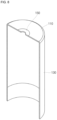
- FIG. 1 is a perspective view of a cylindrical secondary battery according to some embodiments.
- FIG. 2 is a cross-sectional view of the cylindrical secondary battery according to FIG. 1 .
- FIG. 3 is an enlarged cross-sectional view of a portion of a can according to FIG. 1 .
- FIG. 4 is a cross-sectional view illustrating the can and an insulator according to FIG. 3 .
- a cylindrical secondary battery 10 may include a cylindrical can (or cylindrical housing) 100, an electrode assembly 200 accommodated or inserted or housed within the can 100, a first electrode current collecting plate 300 and a second electrode current collecting plate 400, a terminal portion 500 provided at one side of the can 100, and a cap assembly 600 provided at the other side of the can 100.
- the can 100 may include a circular upper surface portion 110, and a cylindrical side portion 130 extending downward from the upper surface portion 110. Because a lower portion of the side portion 130 is open, the can 100 has a cylindrical shape whose lower end is open.
- a terminal hole 110a may be formed through a center of the upper surface portion 110.
- a portion of the terminal portion 500 may be exposed to the outside of the secondary battery 10 through the terminal hole 110a.
- a coupling groove 112 and a coupling protrusion 114 may be provided on an inner surface adjacent to the terminal hole 110a.
- the coupling groove 112 may be formed by forging.
- the coupling groove 112 may have a circular ring shape having a width (e.g., a set or predetermined width) based on a center of the upper surface portion 110 of the can 100.
- a diameter of the terminal hole 110a may be defined as L1.
- an outer diameter of the coupling groove 112 may be formed larger than the diameter of the terminal hole 110a.
- the outer diameter of the coupling groove 112 is a diameter based on an outer edge of the coupling groove 112 in a direction away from the center of the upper surface portion 110.
- a length obtained by subtracting the diameter L1 of the terminal hole 110a from the outer diameter of the coupling groove 112 is defined as the width of the coupling groove 112.
- the width of the coupling groove 112 may be understood as a radial length of the upper surface portion 110 based on FIG. 3 .
- a depth L3 of the coupling groove 112 may refer to a length in a thickness L2 direction of the upper surface portion 110.
- the depth L3 of the coupling groove 112 is a length between the inner surface and the outer surface of the coupling groove 112.
- the coupling groove 112 is concavely processed from the inner surface of the upper surface portion 110 through forging. Accordingly, the depth L3 of the coupling groove 112 is formed smaller than the thickness L2 of the upper surface portion 110.
- the depth L3 of the coupling groove 112 may be 10 to 30% smaller than the thickness L2 of the upper surface portion 110.
- a direction in which the metal is pushed is a direction of or toward the cut surface (a cut side surface) of the terminal hole 110a. Further, the direction in which the metal is pushed and protrudes is a direction toward the electrode assembly 200.
- a portion which is pushed and protrudes may be processed so that a cross-sectional shape thereof becomes triangular.
- the protrusion formed in this way is the coupling protrusion 114.
- a protruding height of the coupling protrusion 114 should be lower than or equal to the inner surface of the upper surface portion 110 of the can 100 to prevent the coupling protrusion 114 from interfering with surrounding components.
- the coupling groove 112 and the coupling protrusion 114 serve to improve or increase a sealing force by increasing a coupling force with an insulator 520, which will be described in more detail below. Accordingly, leakage of an electrolyte accommodated in the can 100 may be prevented or reduced. Further, a frictional force between the insulator 520 and the upper surface portion 110 increases due to the coupling groove 112 and the coupling protrusion 114. Accordingly, the insulator 520 may be very strongly coupled to the upper surface portion 110. Accordingly, even when a rivet terminal 510 moves, the insulator 520 may not move. Accordingly, in order to rotate the rivet terminal 510, a very large rotational pressure may be applied.
- the rotational pressure of the rivet terminal 510 increases compared to a conventional terminal structure. Accordingly, the rivet terminal 510 may not be rotated by general external impacts or vibrations which occur in a use environment of the secondary battery. Accordingly, a problem of the rivet terminal 510 rotating due to an external force may be prevented or reduced.
- the side portion 130 is integrally formed with the upper surface portion 110 as an upper end thereof is connected to the upper surface portion 110.
- a lower end of the side portion 130 is open, and the cap assembly 600 is provided at the open end portion.
- a beading portion 132 may be formed in the side portion 130 adjacent to the lower end.
- the beading portion 132 may be formed concavely inward from the side portion 130.
- the end portion spaced apart from the beading portion 132 may be bent toward the inside of the can 100 to form a crimping portion 134. Separation of the electrode assembly 200 is prevented by the beading portion 132.
- the cap assembly 600 may be located between the beading portion 132 and the crimping portion 134.
- the crimping portion 134 fixes the cap assembly 600 so that the can 100 is sealed.
- the can 100 having the above-described structure may be formed of steel, a steel alloy, aluminum, an aluminum alloy, or equivalents thereof, but the material is not limited here.
- the electrode assembly 200, the first electrode current collecting plate 300, and the second electrode current collecting plate 400 are accommodated in the can 100 together with the electrolyte.
- the electrode assembly 200 may have a form in which a first electrode plate 210, a second electrode plate 220, and a separator 230 interposed therebetween are wound in a cylindrical form.
- the first electrode plate 210 may be a positive electrode plate
- the second electrode plate 220 may be a negative electrode plate.
- the opposite may also be possible.
- a positive electrode active material layer 212 may be formed on at least one surface of an aluminum (Al) foil by coating or the like.
- the positive electrode active material layer 212 may be formed of a transition metal oxide (LiCoO 2 , LiNiO 2 , LiMn 2 O 4 , or the like).
- a first electrode uncoated portion where the positive electrode active material layer 212 is not formed may be provided in the first electrode plate 210.
- a plurality of first electrode substrate tabs 214 may be formed by cutting the first electrode uncoated portion into a shape (e.g., a set or predetermined shape) by notching or the like.
- the first electrode substrate tab 214 may be arranged toward the upper surface portion 110 of the can 100. Further, the first electrode substrate tab 214 may protrude further upward than the separator 230 to be electrically connected to the first electrode current collecting plate 300.
- a negative electrode active material layer 222 may be formed on at least one surface of a copper or nickel foil by coating or the like.
- the negative electrode active material layer 222 may be formed of graphite, carbon, or the like.
- a second electrode uncoated portion where the negative electrode active material layer 222 is not formed may be provided in the second electrode plate 220.
- a plurality of second electrode substrate tabs 224 may be formed by cutting the second electrode uncoated portion into a shape (e.g., a set or predetermined shape) by notching or the like. According to some embodiments, the second electrode substrate tab 224 may be arranged toward the bottom of the can 100.
- the second electrode substrate tab 224 may protrude further downward than the separator 230 to be electrically connected to the second electrode current collecting plate 400. Some of the second electrode substrate tabs 224 may be welded and electrically connected to the beading portion 132 of the can 100.
- the separator 230 may be polyethylene (PE) or polypropylene (PP), but is not limited thereto in the present disclosure.
- the separator 230 may prevent or reduce instances of an electrical short circuit between the first electrode plate 210 and the second electrode plate 220 and allow only the movement of lithium ions.
- the electrode assembly 200 having the above-described structure is electrically connected to the first electrode current collecting plate 300 and the second electrode current collecting plate 400 and electrically connected to the terminal portion 500 and the can 100.
- the first electrode current collecting plate 300 has a disk shape and may be made of the same material as the first electrode plate 210.
- the first electrode current collecting plate 300 may be formed of aluminum or an aluminum alloy.
- a diameter of the first electrode current collecting plate 300 may be smaller than a diameter of the can 100 to prevent the first electrode current collecting plate 300 from being electrically connected to the can 100.
- the first electrode current collecting plate 300 may be welded in a state in which a lower surface thereof is in contact with the first electrode substrate tab 214.
- the first electrode current collecting plate 300 and the first electrode plate 210 may be electrically connected. Further, an upper surface of the first electrode current collecting plate 300 may be welded to the rivet terminal 510 of the terminal portion 500, which will be described below. Accordingly, the first electrode current collecting plate 300 and the rivet terminal 510 may be electrically connected. Accordingly, the first electrode plate 210 and the rivet terminal 510 may be electrically connected to each other by the first electrode current collecting plate 300. That is, the first electrode current collecting plate 300 may become a path for the flow of current between the first electrode plate 210 and the rivet terminal 510.
- the second electrode current collecting plate 400 may include a disk-shaped plate surface portion 410 and a contact portion 420 extending from the plate surface portion 410.
- An upper surface of the plate surface portion 410 may be welded while in contact with the second electrode substrate tab 224. Accordingly, the second electrode current collecting plate 400 and the second electrode plate 220 may be electrically connected.
- the second electrode current collecting plate 400 may be made of the same material as the second electrode plate 220.
- the second electrode current collecting plate 400 may be made of copper.
- the contact portion 420 may extend downward from an edge of the plate surface portion 410. The contact portion 420 may be in close contact with an inner surface of the beading portion 132.
- the contact portion 420 may have a curve corresponding to a curve of the beading portion 132.
- the contact portion 420 may be welded and electrically connected to the beading portion 132.
- the second electrode current collecting plate 400 is not electrically connected to the cap assembly 600.
- the terminal portion 500 may include the rivet terminal 510 and at least one insulator 520 for insulating the rivet terminal 510.
- the rivet terminal 510 is inserted into the terminal hole 110a formed in the upper surface portion 110 of the can 100.
- the rivet terminal 510 is electrically connected to the first electrode plate 210 through the first electrode current collecting plate 300.
- the rivet terminal 510 is a terminal coupled to the upper surface portion 110 of the can 100 by a riveting method.
- the rivet terminal 510 may be inserted into the terminal hole 110a from the outside toward the inside of the can 100.
- one end of the rivet terminal 510 is located on the outside of the can 100, and the other end is located on the inside of the can 100.
- at least one insulator 520 may be inserted between the rivet terminal 510 and the upper surface portion 110 of the can 100 to insulate the can 100 and the rivet terminal 510.
- an inner end portion of the rivet terminal 510 is compressed and deformed through processing such as pressing, spinning, or the like. Accordingly, the rivet terminal 510 may be in close contact with the upper surface portion 110 of the can 100.
- the insulator 520 may be made of an insulating material.
- the insulator 520 may have a cross-sectional shape in which an approximate 'H' shape is laid down.
- the insulator 520 may be used without limitation as long as it does not dissolve in the electrolyte and is made of an insulating material.
- the insulator 520 may have appropriate elasticity for close coupling with the upper surface portion 110 of the can 100 and the rivet terminal 510 through pressurization.
- a coupling portion 528 coupled to the above-described coupling groove 112 may be provided on the insulator 520. As shown in FIGS.
- the insulator 520 may include a disk-shaped first portion 522 located outside the upper surface portion 110 and a disk-shaped second portion 524 located inside the upper surface portion 110, and a cylindrical third portion 526 which connects the first portion 522 and the second portion 524.
- the above-described coupling portion 528 may be formed on the second portion 524.
- the second portion 524 may have a length sufficiently extending outside the coupling groove 112 of the upper surface portion 110.
- the length of the second portion 524 may be 2 to 3 times the length of the coupling groove 112.
- the second portion 524 may be provided to be larger than the first electrode current collecting plate 300.
- the first portion 522 to the third portion 526 may be integrally formed, or may be formed separately and coupled to the upper surface portion 110. Embodiments according to present disclosure have been described herein based on an example in which the first portion 522 to the third portion 526 are integrally formed.
- the coupling portion 528 is formed to protrude from an upper surface of the second portion 524 based on FIG. 2 , and is formed to protrude from a lower surface of the second portion 524 based on FIG. 4 .
- the coupling portion 528 is formed to correspond to a position of the coupling groove 112, and the coupling portion 528 has a protrusion shape corresponding to a shape of the coupling groove 112.
- the coupling portion 528 may be a circular ring-shaped protrusion.
- the insulator 520 may additionally include a groove corresponding to the coupling protrusion 114. However, because the insulator 520 is elastic and may come into close contact with the coupling protrusion 114, the groove corresponding to the coupling protrusion 114 need not be provided.
- the cap assembly 600 may include a cap plate 610 for sealing the can 100 and a gasket 620 which insulates between the can 100 and the cap plate 610.
- the cap plate 610 may include a disk-shaped flat surface portion 612, an inclined surface 614 connected to the flat surface portion 612, and an extending surface 616 connected to the inclined surface 614.
- the flat surface portion 612 may be arranged substantially parallel to the second electrode current collecting plate 400.
- the inclined surface 614 may extend to be inclined downward from an edge of the flat surface portion 612.
- the extending surface 616 may extend from an edge of the inclined surface 614 and may be parallel to the flat surface portion 612.
- the extending surface 616 may be located between the beading portion 132 and the crimping portion 134 in a state of being surrounded by the gasket 620.
- a notch 612a may be formed in the flat surface portion 612.
- the notch 612a may be broken based on a pressure in the secondary battery 10 being greater than or equal to a pressure (e.g., a set or predetermined pressure). A gas in the secondary battery 10 may be discharged when the notch 612a is broken. That is, the notch 612a serves as a vent.
- a pressure e.g., a set or predetermined pressure
- the gasket 620 is located between a lower portion of the beading portion 132 and the crimping portion 134 and may surround the extending surface 616 of the cap plate 610.
- the gasket 620 may cover a part or all of the extending surface 616.
- a side where the gasket 620 and the extending surface 616 are in contact with each other may be defined as the inside, and a side where the gasket 620 is in contact with the beading portion 132 may be defined as the outside.
- a portion of the contact portion 420 of the second electrode current collecting plate 400 may be inserted between an outer upper portion of the gasket 620 and the beading portion 132.
- the contact portion 420 of the second electrode current collecting plate 400 and the extending surface 616 of the cap plate 610 are not in contact with each other due to the gasket 620. That is, the gasket 620 may insulate the cap plate 610 and the can 100 from each other, and may insulate the cap plate 610 and the second electrode current collecting plate 400 from each other.
- the rivet terminal 510 has a positive polarity and the can 100 has a negative polarity. Accordingly, it has a structure in which both a positive electrode and a negative electrode are located at the top of the can 100.
- an anti-corrosion material (or layer or means) for preventing or reducing corrosion or rust in areas where corrosion or rust may occur in the above-described example cylindrical secondary battery will be described below in more detail.
- FIG. 5 is a schematic diagram briefly illustrating an anti-corrosion portion according to some embodiments of the present disclosure.
- an anti-corrosion material 700 may be provided in a region between the end portion of the side portion 130 and an upper surface of the gasket 620.
- the anti-corrosion material 700 may be an anti-corrosion liquid according to some embodiments.
- an end portion of the crimping portion 134 which is an end portion of the side portion 130 (an end portion opposite a bottom portion), has a cut surface 134a formed by cutting a metal plate, which is the material of the can 100. Because the cut surface 134a is a portion exposed to the air, there is a risk of corrosion.
- the gasket 620 is present between the crimping portion 134 and the cap plate 610, corrosion may occur at the end portion of the crimping portion 134 even due to slight leakage of the electrolyte due to repeated use of the secondary battery 10. When corrosion becomes severe, rust may occur and affect the quality of the secondary battery such as a sealing force or the like.
- a portion vulnerable to corrosion or rust is a cut portion where a raw material is cut, such as the end portion of the crimping portion 134, a welding portion, and a molding portion such as a trimming portion, or the like. Accordingly, in order to prevent or reduce the risk of the corrosion or rust, a structure in which the anti-corrosion material 700 is applied to the above-described portions will be proposed.
- an example in which the anti-corrosion material 700 is provided is the end portion of the crimping portion 134.
- the cap plate 610 is located closer to the electrode assembly than the end portion of the crimping portion 134.
- the anti-corrosion material 700 may be provided to sufficiently cover the cut surface 134a of the end portion of the crimping portion 134 so that the cut surface 134a is not exposed to the air.
- the anti-corrosion material 700 may be entirely provided in a region (e.g., a set or predetermined region) including the end portion of the crimping portion 134 and the end portion of the gasket 620.
- the gasket 620 may not protrude beyond the end portion of the crimping portion 134, or may protrude more. When the gasket 620 protrudes more than the crimping portion 134, the anti-corrosion material 700 may entirely fill a region from the end portion of the crimping portion 134 to the end portion of the gasket 620.
- the anti-corrosion material 700 may be an anti-corrosion liquid which is one of a normal material such as an ethylene-vinyl acetate copolymer (EVA), a polyethylene (PE) material, a polypropylene (PP) material, or the like and a hot-melt material such as a BU-302 material having heat resistant/flame retardant characteristics or the like, or a combination of two or more.
- EVA ethylene-vinyl acetate copolymer
- PE polyethylene
- PP polypropylene
- hot-melt material such as a BU-302 material having heat resistant/flame retardant characteristics or the like, or a combination of two or more.
- the anti-corrosion material 700 may be an acrylic or olefin adhesive, a potting material (e.g., foamed silicone filled between cells of a battery pack)/UV solution, general oil-based paint, a zinc primer, or the like.
- FIGS. 6 and 7 are schematic diagrams briefly illustrating anti-corrosion portions according to some embodiments of the present disclosure.
- a cap plate 610' may have a curve.
- an edge of the cap plate 610' may be located closer to the electrode assembly than the end portion of the crimping portion 134.
- a portion of the cap plate 610' may protrude further outward than the end portion of the crimping portion 134.
- the gasket 620 may be located between the end portion of the crimping portion 134 and a maximally protruding surface of the cap plate 610' (hereinafter, a maximally protruding surface 61 0a').
- an anti-corrosion material 700' may entirely fill a region between the end portion of the crimping portion 134 and the maximally protruding surface 610a' of the cap plate 610'.
- the anti-corrosion material 700' may be provided only up to the end portion of the crimping portion 134 and the end portion of the gasket 620.
- a cap plate 610" has a straight plate shape, and an edge of the cap plate 610" may be coupled to a side portion 130" by welding without crimping.
- a thin insulating film may be provided between the side portion 130" and the cap plate 610" instead of the gasket.
- an anti-corrosion material 700" may be provided to sufficiently cover a welding portion and a cut surface 134" of an end portion of the side portion 130".
- a protrusion or rib 130a" or 61 0a” may be provided to prevent the anti-corrosion liquid from flowing to the outside of the side portion 130" or a center of the cap plate 610".
- the protrusion or rib 130a" or 610a” may be formed on either or both the side portion 130" and the cap plate 610".
- An example shape of the protrusion or rib 130a" or 610a” is shown in a dotted line in FIG. 7 .
- the protrusion or rib 130a" or 610a” may be provided to be lower than a height of a weld bead formed in the welding portion. Because FIG.
- the protrusion or rib 130a" or 610a” is shown as one.
- the side portion 130" has a cylindrical shape and the cap plate 610" has a circular shape
- the protrusion or rib 130a" or 610a” may have a circular ring shape when viewed from above (e.g., in a plan view).
- a concave groove 610b" may be formed instead of the protrusion or rib 130a" or 610a" on the cap plate 610" to prevent or reduce the anti-corrosion liquid from flowing.
- the above-described groove may be formed through forging.
- the groove 610b" may also have a circular ring shape when viewed from above (e.g., in a plan view).
- anti-corrosion material 700 may also be provided in a terminal hole portion in all of the above-described embodiments.
- FIG. 8 is a schematic diagram briefly illustrating examples of anti-corrosion portions according to some embodiments of the present disclosure.
- all of the secondary batteries 10 according to some embodiments as illustrated in FIGS. 5 to 7 may have the same terminal portion structure.
- the above-described anti-corrosion material may also be provided in the terminal hole to which the above-described rivet terminal 510 is coupled and a peripheral region 150.
- the terminal hole is a portion where the cut surface is formed by cutting the upper surface portion 110 of the can 100, and thus may also be vulnerable to corrosion. Accordingly, for example, the anti-corrosion liquid may be applied to cover the terminal hole and the peripheral region 150 thereof.
- a cylindrical secondary battery according to some embodiments of the present disclosure is corrosion-resistant so that a cut surface or welding surface prone to corrosion or rust is not exposed to air. Accordingly, the occurrence of corrosion or rust on the cut surface or welding surface can be prevented or reduced.
Landscapes
- Chemical & Material Sciences (AREA)
- Chemical Kinetics & Catalysis (AREA)
- Electrochemistry (AREA)
- General Chemical & Material Sciences (AREA)
- Inorganic Chemistry (AREA)
- Engineering & Computer Science (AREA)
- Manufacturing & Machinery (AREA)
- Connection Of Batteries Or Terminals (AREA)
- Sealing Battery Cases Or Jackets (AREA)
Abstract
A cylindrical secondary battery includes: an electrode assembly; a can accommodating the electrode assembly therein, and including an upper surface portion in which a terminal hole is formed at one end, and a cylindrical side portion extending downward from the upper surface portion; a terminal portion coupled to the terminal hole and electrically connected to the electrode assembly; a cap plate coupled to an end portion of the side portion and electrically connected to the electrode assembly; and an anticorrosion material at a coupling portion of the side portion and the cap plate.
Description
- Aspects of some embodiments of the present disclosure relate to a cylindrical secondary battery having a corrosion-resistant structure.
- Recently, consumer demand for secondary batteries having a form in which both positive electrode and negative electrode terminals are located at one side of the secondary battery is increasing. This type of secondary battery may have an advantage in that an electrical connection structure with the outside is relatively simple.
- In the above-described secondary batteries, one side of a cylindrical can or housing may be open, and an electrode assembly may be accommodated therein with an electrolyte. A cap assembly may be coupled to the open one side of the can. In the case of a can, when a cut surface such as the open one side is exposed to air for a long time, corrosion can occur and thus rust can occur. Alternatively, corrosion can occur at a coupling portion (a welded portion) between the cap assembly and the can due to influence of the electrolyte.
- Corrosion and rust can cause the functions of the secondary battery to deteriorate, and thus may desirably be prevented.
- The above information disclosed in this Background section is only for enhancement of understanding of the background and therefore the information discussed in this Background section does not necessarily constitute prior art.
- The invention is defined by the appended claims. The description that follows is subjected to this limitation. Any disclosure lying outside the scope of said claims is only intended for illustrative as well as comparative purposes. Aspects of some embodiments of the present disclosure include a cylindrical secondary battery having a corrosion-resistant structure.
- A cylindrical secondary battery according to some embodiments of the present disclosure includes: an electrode assembly; a can accommodating the electrode assembly therein, and including an upper surface portion in which a terminal hole is formed at one end, and a cylindrical side portion extending downward from the upper surface portion; a terminal portion coupled to the terminal hole to be electrically connected to the electrode assembly; a cap plate coupled to an end portion of the side portion to be electrically connected to the electrode assembly; and an anti-corrosion material or means provided at a coupling portion of the side portion and the cap plate.
- According to some embodiments, the side portion may include a beading portion concavely formed on an upper portion of the cap plate, and a crimping portion spaced apart from the beading portion and whose end portion is formed to be bent inward, and the cap plate may be between the beading portion and the crimping portion.
- According to some embodiments, the cylindrical secondary battery may further include a gasket inserted between the cap plate and the side portion.
- According to some embodiments, the anti-corrosion material may be provided to cover the end portion of the crimping portion.
- According to some embodiments, the anti-corrosion material may be provided to cover the end portion of the crimping portion and an end portion of the gasket.
- According to some embodiments, the anti-corrosion material may be provided to cover the end portion of the crimping portion, an end portion of the gasket, and a portion of the cap plate.
- According to some embodiments, the cap plate may be welded to the side portion.
- According to some embodiments, the anti-corrosion material may be provided to cover the end portion of the side portion.
- According to some embodiments, the anti-corrosion material may be provided to cover a welding portion of the end portion of the side portion and the cap plate.
- According to some embodiments, the anti-corrosion material may be an anti-corrosion liquid.
- According to some embodiments, the cylindrical secondary battery may further include a protrusion or rib formed to protrude from at least one surface of an outer end portion of the side portion and one side of the cap plate adjacent to the welding portion.
- According to some embodiments, the protrusion or rib may have a lower height than a weld bead formed in the welding portion of the cap plate.
- According to some embodiments, the protrusion or rib may have a circular ring shape.
- According to some embodiments, the cap plate may further include a groove concavely formed from a surface adjacent to the welding portion.
- Further, a cylindrical secondary battery according to some embodiments of the present disclosure includes: an electrode assembly; a can accommodating the electrode assembly therein, and including an upper surface portion in which a terminal hole is formed at one end, and a cylindrical side portion extending downward from the upper surface portion; a terminal portion coupled to the terminal hole to be electrically connected to the electrode assembly; a cap plate coupled to an end portion of the side portion to be electrically connected to the electrode assembly and insulated from the can; and an anti-corrosion material provided at a coupling portion of the terminal hole and the terminal portion.
- According to some embodiments, the anti-corrosion material may be provided to cover a portion of a cut surface of the terminal hole and a portion of the upper surface portion adjacent to the terminal hole.
- According to some embodiments, the anti-corrosion material may be an anti-corrosion liquid.
- According to some embodiments, the cylindrical secondary battery may further include a coupling groove and a coupling protrusion formed adjacent to the terminal hole by forging.
- According to some embodiments, the coupling groove may be concavely formed from a surface of the upper surface portion, a depth of the coupling groove may be lower than a thickness of the upper surface portion, and the coupling protrusion may be formed adjacent to the coupling groove and faces the inside of the can.
- According to some embodiments, the terminal portion may include a rivet terminal inserted into the terminal hole to be electrically connected to the electrode assembly and at least one insulator interposed between the rivet terminal and the can to insulate the rivet terminal and the can.
-
-
FIG. 1 is a perspective view of a cylindrical secondary battery according to some embodiments. -
FIG. 2 is a cross-sectional view of the cylindrical secondary battery according toFIG. 1 . -
FIG. 3 is an enlarged cross-sectional view of a portion of a can according toFIG. 1 . -
FIG. 4 is a cross-sectional view illustrating the can and an insulator according toFIG. 3 . -
FIG. 5 is a schematic diagram briefly illustrating an anti-corrosion portion according to some embodiments of the present disclosure. -
FIGS. 6 and7 are schematic diagrams briefly illustrating anti-corrosion portions according to some embodiments of the present disclosure. -
FIG. 8 is a schematic diagram briefly illustrating examples of anti-corrosion portions according to some embodiments of the present disclosure. - Aspects of some embodiments of the present disclosure are provided to more completely describe the present disclosure to those skilled in the art, the following embodiments may be modified into various other forms, and the scope of the present disclosure not limited to the following embodiments. Rather, these embodiments are provided to make the present disclosure more meaningful and complete and to fully convey the spirit of the present disclosure to those skilled in the art.
- Further, in the accompanying drawings, a thickness and a size of each layer are exaggerated for convenience and clarity of description, and the same reference numerals indicate the same elements in the drawings. As used in the present specification, the term "and/or" includes any one of and all combinations of one or more of the listed items. Further, the meaning of "being connected" in the present specification refers to not only a case in which member A and member B are directly connected, but also a case in which member C is interposed between member A and member B to indirectly connect member A and member B.
- The terms used in the present specification are used to describe specific embodiments and are not intended to limit the present disclosure. As used in the present specification, a singular form may include a plural form unless the context clearly indicates otherwise. Further, when used in the present specification, "comprise" and/or "comprising" specify(ies) the presence of mentioned features, numbers, steps, operations, members, elements and/or groups thereof, and do(es) not exclude the presence or addition of one or more other features, numbers, steps, operations, members, elements and/or groups.
- Although the terms first, second, and the like are used in the present specification to describe various members, components, regions, layers and/or parts, it is clear that these members, components, regions, layers and/or parts should not be limited by these terms. These terms are used only to distinguish one member, component, region, layer, or part from another member, component, region, layer, or part. Accordingly, a first member, component, region, layer, or part to be described later may refer to a second member, component, region, layer, or part without departing from teachings of the present disclosure.
- Spatially-related terms such as "beneath," "below," "lower," "above," and "upper" are used for easy understanding of one element or feature and another element or feature shown in the drawings. These spatially-related terms are provided for easy understanding of the present disclosure according to various process states or usage states of the present disclosure and are not intended to limit the present disclosure. For example, when the elements or features in the drawings are reversed, an element described as "lower" or "below" "becomes "upper" or "above." Accordingly, "below" is a concept encompassing "above" or "below."
- Here, a cylindrical secondary battery according to some embodiments of the present disclosure and a manufacturing method thereof will be described with reference to the accompanying drawings. In the following description, the cylindrical secondary battery will be described by defining an upper side as an upper direction and defining a lower side as a lower direction based on
FIGS. 1 and2 for convenience. -
FIG. 1 is a perspective view of a cylindrical secondary battery according to some embodiments.FIG. 2 is a cross-sectional view of the cylindrical secondary battery according toFIG. 1 .FIG. 3 is an enlarged cross-sectional view of a portion of a can according toFIG. 1 .FIG. 4 is a cross-sectional view illustrating the can and an insulator according toFIG. 3 . - As shown in
FIGS. 1 and2 , a cylindricalsecondary battery 10 according to some embodiments of the present disclosure may include a cylindrical can (or cylindrical housing) 100, anelectrode assembly 200 accommodated or inserted or housed within thecan 100, a first electrodecurrent collecting plate 300 and a second electrodecurrent collecting plate 400, aterminal portion 500 provided at one side of thecan 100, and acap assembly 600 provided at the other side of thecan 100. - As shown in
FIGS. 1 and2 , thecan 100 may include a circularupper surface portion 110, and acylindrical side portion 130 extending downward from theupper surface portion 110. Because a lower portion of theside portion 130 is open, thecan 100 has a cylindrical shape whose lower end is open. - As shown in
FIGS. 3 and 4 , aterminal hole 110a may be formed through a center of theupper surface portion 110. A portion of theterminal portion 500 may be exposed to the outside of thesecondary battery 10 through theterminal hole 110a. Acoupling groove 112 and acoupling protrusion 114 may be provided on an inner surface adjacent to theterminal hole 110a. - The
coupling groove 112 may be formed by forging. Thecoupling groove 112 may have a circular ring shape having a width (e.g., a set or predetermined width) based on a center of theupper surface portion 110 of thecan 100. A diameter of theterminal hole 110a may be defined as L1. In this case, an outer diameter of thecoupling groove 112 may be formed larger than the diameter of theterminal hole 110a. The outer diameter of thecoupling groove 112 is a diameter based on an outer edge of thecoupling groove 112 in a direction away from the center of theupper surface portion 110. A length obtained by subtracting the diameter L1 of theterminal hole 110a from the outer diameter of thecoupling groove 112 is defined as the width of thecoupling groove 112. In other words, the width of thecoupling groove 112 may be understood as a radial length of theupper surface portion 110 based onFIG. 3 . - Further, a depth L3 of the
coupling groove 112 may refer to a length in a thickness L2 direction of theupper surface portion 110. The depth L3 of thecoupling groove 112 is a length between the inner surface and the outer surface of thecoupling groove 112. Thecoupling groove 112 is concavely processed from the inner surface of theupper surface portion 110 through forging. Accordingly, the depth L3 of thecoupling groove 112 is formed smaller than the thickness L2 of theupper surface portion 110. For example, the depth L3 of thecoupling groove 112 may be 10 to 30% smaller than the thickness L2 of theupper surface portion 110. - When the
coupling groove 112 is forged from theupper surface portion 110, metal is pushed and protrudes outward by the amount of processing. In this case, a direction in which the metal is pushed is a direction of or toward the cut surface (a cut side surface) of theterminal hole 110a. Further, the direction in which the metal is pushed and protrudes is a direction toward theelectrode assembly 200. When thecoupling groove 112 is formed, a portion which is pushed and protrudes may be processed so that a cross-sectional shape thereof becomes triangular. The protrusion formed in this way is thecoupling protrusion 114. A protruding height of thecoupling protrusion 114 should be lower than or equal to the inner surface of theupper surface portion 110 of thecan 100 to prevent thecoupling protrusion 114 from interfering with surrounding components. - The
coupling groove 112 and thecoupling protrusion 114 serve to improve or increase a sealing force by increasing a coupling force with aninsulator 520, which will be described in more detail below. Accordingly, leakage of an electrolyte accommodated in thecan 100 may be prevented or reduced. Further, a frictional force between theinsulator 520 and theupper surface portion 110 increases due to thecoupling groove 112 and thecoupling protrusion 114. Accordingly, theinsulator 520 may be very strongly coupled to theupper surface portion 110. Accordingly, even when arivet terminal 510 moves, theinsulator 520 may not move. Accordingly, in order to rotate therivet terminal 510, a very large rotational pressure may be applied. That is, the rotational pressure of therivet terminal 510 increases compared to a conventional terminal structure. Accordingly, therivet terminal 510 may not be rotated by general external impacts or vibrations which occur in a use environment of the secondary battery. Accordingly, a problem of therivet terminal 510 rotating due to an external force may be prevented or reduced. - The
side portion 130 is integrally formed with theupper surface portion 110 as an upper end thereof is connected to theupper surface portion 110. A lower end of theside portion 130 is open, and thecap assembly 600 is provided at the open end portion. Abeading portion 132 may be formed in theside portion 130 adjacent to the lower end. Thebeading portion 132 may be formed concavely inward from theside portion 130. The end portion spaced apart from thebeading portion 132 may be bent toward the inside of thecan 100 to form a crimpingportion 134. Separation of theelectrode assembly 200 is prevented by thebeading portion 132. Thecap assembly 600 may be located between thebeading portion 132 and the crimpingportion 134. The crimpingportion 134 fixes thecap assembly 600 so that thecan 100 is sealed. - The can 100 having the above-described structure may be formed of steel, a steel alloy, aluminum, an aluminum alloy, or equivalents thereof, but the material is not limited here. The
electrode assembly 200, the first electrodecurrent collecting plate 300, and the second electrodecurrent collecting plate 400 are accommodated in thecan 100 together with the electrolyte. - As shown in
FIG. 2 , theelectrode assembly 200 may have a form in which afirst electrode plate 210, asecond electrode plate 220, and aseparator 230 interposed therebetween are wound in a cylindrical form. According to some embodiments, thefirst electrode plate 210 may be a positive electrode plate, and thesecond electrode plate 220 may be a negative electrode plate. However, the opposite may also be possible. - In the
first electrode plate 210, a positive electrode active material layer 212 may be formed on at least one surface of an aluminum (Al) foil by coating or the like. For example, the positive electrode active material layer 212 may be formed of a transition metal oxide (LiCoO2, LiNiO2, LiMn2O4, or the like). A first electrode uncoated portion where the positive electrode active material layer 212 is not formed may be provided in thefirst electrode plate 210. A plurality of first electrode substrate tabs 214 may be formed by cutting the first electrode uncoated portion into a shape (e.g., a set or predetermined shape) by notching or the like. According to some embodiments, the first electrode substrate tab 214 may be arranged toward theupper surface portion 110 of thecan 100. Further, the first electrode substrate tab 214 may protrude further upward than theseparator 230 to be electrically connected to the first electrodecurrent collecting plate 300. - In the
second electrode plate 220, a negative electrode active material layer 222 may be formed on at least one surface of a copper or nickel foil by coating or the like. For example, the negative electrode active material layer 222 may be formed of graphite, carbon, or the like. A second electrode uncoated portion where the negative electrode active material layer 222 is not formed may be provided in thesecond electrode plate 220. A plurality of second electrode substrate tabs 224 may be formed by cutting the second electrode uncoated portion into a shape (e.g., a set or predetermined shape) by notching or the like. According to some embodiments, the second electrode substrate tab 224 may be arranged toward the bottom of thecan 100. Further, the second electrode substrate tab 224 may protrude further downward than theseparator 230 to be electrically connected to the second electrodecurrent collecting plate 400. Some of the second electrode substrate tabs 224 may be welded and electrically connected to thebeading portion 132 of thecan 100. - The
separator 230 may be polyethylene (PE) or polypropylene (PP), but is not limited thereto in the present disclosure. Theseparator 230 may prevent or reduce instances of an electrical short circuit between thefirst electrode plate 210 and thesecond electrode plate 220 and allow only the movement of lithium ions. - The
electrode assembly 200 having the above-described structure is electrically connected to the first electrodecurrent collecting plate 300 and the second electrodecurrent collecting plate 400 and electrically connected to theterminal portion 500 and thecan 100. - As shown in
FIG. 2 , the first electrodecurrent collecting plate 300 has a disk shape and may be made of the same material as thefirst electrode plate 210. For example, the first electrodecurrent collecting plate 300 may be formed of aluminum or an aluminum alloy. A diameter of the first electrodecurrent collecting plate 300 may be smaller than a diameter of thecan 100 to prevent the first electrodecurrent collecting plate 300 from being electrically connected to thecan 100. The first electrodecurrent collecting plate 300 may be welded in a state in which a lower surface thereof is in contact with the first electrode substrate tab 214. - Accordingly, the first electrode
current collecting plate 300 and thefirst electrode plate 210 may be electrically connected. Further, an upper surface of the first electrodecurrent collecting plate 300 may be welded to therivet terminal 510 of theterminal portion 500, which will be described below. Accordingly, the first electrodecurrent collecting plate 300 and therivet terminal 510 may be electrically connected. Accordingly, thefirst electrode plate 210 and therivet terminal 510 may be electrically connected to each other by the first electrodecurrent collecting plate 300. That is, the first electrodecurrent collecting plate 300 may become a path for the flow of current between thefirst electrode plate 210 and therivet terminal 510. - As shown in
FIG. 2 , the second electrodecurrent collecting plate 400 may include a disk-shapedplate surface portion 410 and acontact portion 420 extending from theplate surface portion 410. An upper surface of theplate surface portion 410 may be welded while in contact with the second electrode substrate tab 224. Accordingly, the second electrodecurrent collecting plate 400 and thesecond electrode plate 220 may be electrically connected. To this end, the second electrodecurrent collecting plate 400 may be made of the same material as thesecond electrode plate 220. For example, the second electrodecurrent collecting plate 400 may be made of copper. According to some embodiments, thecontact portion 420 may extend downward from an edge of theplate surface portion 410. Thecontact portion 420 may be in close contact with an inner surface of thebeading portion 132. To this end, thecontact portion 420 may have a curve corresponding to a curve of thebeading portion 132. For example, thecontact portion 420 may be welded and electrically connected to thebeading portion 132. However, the second electrodecurrent collecting plate 400 is not electrically connected to thecap assembly 600. - Meanwhile, as shown in
FIGS. 1 and2 , theterminal portion 500 may include therivet terminal 510 and at least oneinsulator 520 for insulating therivet terminal 510. - The
rivet terminal 510 is inserted into theterminal hole 110a formed in theupper surface portion 110 of thecan 100. Therivet terminal 510 is electrically connected to thefirst electrode plate 210 through the first electrodecurrent collecting plate 300. Therivet terminal 510 is a terminal coupled to theupper surface portion 110 of thecan 100 by a riveting method. Therivet terminal 510 may be inserted into theterminal hole 110a from the outside toward the inside of thecan 100. - In this case, one end of the
rivet terminal 510 is located on the outside of thecan 100, and the other end is located on the inside of thecan 100. When therivet terminal 510 is coupled, at least oneinsulator 520 may be inserted between therivet terminal 510 and theupper surface portion 110 of thecan 100 to insulate thecan 100 and therivet terminal 510. In a state in which therivet terminal 510 is inserted into theterminal hole 110a, an inner end portion of therivet terminal 510 is compressed and deformed through processing such as pressing, spinning, or the like. Accordingly, therivet terminal 510 may be in close contact with theupper surface portion 110 of thecan 100. - The
insulator 520 may be made of an insulating material. Theinsulator 520 may have a cross-sectional shape in which an approximate 'H' shape is laid down. Theinsulator 520 may be used without limitation as long as it does not dissolve in the electrolyte and is made of an insulating material. Further, theinsulator 520 may have appropriate elasticity for close coupling with theupper surface portion 110 of thecan 100 and therivet terminal 510 through pressurization. Referring toFIG. 4 , acoupling portion 528 coupled to the above-describedcoupling groove 112 may be provided on theinsulator 520. As shown inFIGS. 2 and4 , theinsulator 520 may include a disk-shapedfirst portion 522 located outside theupper surface portion 110 and a disk-shapedsecond portion 524 located inside theupper surface portion 110, and a cylindricalthird portion 526 which connects thefirst portion 522 and thesecond portion 524. The above-describedcoupling portion 528 may be formed on thesecond portion 524. - Further, the
second portion 524 may have a length sufficiently extending outside thecoupling groove 112 of theupper surface portion 110. For example, the length of thesecond portion 524 may be 2 to 3 times the length of thecoupling groove 112. Further, for example, when there is no separate insulating member between the first electrodecurrent collecting plate 300 and the can, thesecond portion 524 may be provided to be larger than the first electrodecurrent collecting plate 300. Thefirst portion 522 to thethird portion 526 may be integrally formed, or may be formed separately and coupled to theupper surface portion 110. Embodiments according to present disclosure have been described herein based on an example in which thefirst portion 522 to thethird portion 526 are integrally formed. Thecoupling portion 528 is formed to protrude from an upper surface of thesecond portion 524 based onFIG. 2 , and is formed to protrude from a lower surface of thesecond portion 524 based onFIG. 4 . Thecoupling portion 528 is formed to correspond to a position of thecoupling groove 112, and thecoupling portion 528 has a protrusion shape corresponding to a shape of thecoupling groove 112. When viewed in a plan view, because thecoupling groove 112 is a circular groove, thecoupling portion 528 may be a circular ring-shaped protrusion. According to some embodiments, theinsulator 520 may additionally include a groove corresponding to thecoupling protrusion 114. However, because theinsulator 520 is elastic and may come into close contact with thecoupling protrusion 114, the groove corresponding to thecoupling protrusion 114 need not be provided. - As shown in
FIG. 2 , thecap assembly 600 may include acap plate 610 for sealing thecan 100 and agasket 620 which insulates between thecan 100 and thecap plate 610. - The
cap plate 610 may include a disk-shapedflat surface portion 612, aninclined surface 614 connected to theflat surface portion 612, and an extendingsurface 616 connected to theinclined surface 614. Theflat surface portion 612 may be arranged substantially parallel to the second electrodecurrent collecting plate 400. Theinclined surface 614 may extend to be inclined downward from an edge of theflat surface portion 612. The extendingsurface 616 may extend from an edge of theinclined surface 614 and may be parallel to theflat surface portion 612. The extendingsurface 616 may be located between thebeading portion 132 and the crimpingportion 134 in a state of being surrounded by thegasket 620. Anotch 612a may be formed in theflat surface portion 612. Thenotch 612a may be broken based on a pressure in thesecondary battery 10 being greater than or equal to a pressure (e.g., a set or predetermined pressure). A gas in thesecondary battery 10 may be discharged when thenotch 612a is broken. That is, thenotch 612a serves as a vent. - The
gasket 620 is located between a lower portion of thebeading portion 132 and the crimpingportion 134 and may surround the extendingsurface 616 of thecap plate 610. Thegasket 620 may cover a part or all of the extendingsurface 616. A side where thegasket 620 and the extendingsurface 616 are in contact with each other may be defined as the inside, and a side where thegasket 620 is in contact with thebeading portion 132 may be defined as the outside. In this case, a portion of thecontact portion 420 of the second electrodecurrent collecting plate 400 may be inserted between an outer upper portion of thegasket 620 and thebeading portion 132. Accordingly, thecontact portion 420 of the second electrodecurrent collecting plate 400 and the extendingsurface 616 of thecap plate 610 are not in contact with each other due to thegasket 620. That is, thegasket 620 may insulate thecap plate 610 and thecan 100 from each other, and may insulate thecap plate 610 and the second electrodecurrent collecting plate 400 from each other. - According to the above-described structure, the
rivet terminal 510 has a positive polarity and thecan 100 has a negative polarity. Accordingly, it has a structure in which both a positive electrode and a negative electrode are located at the top of thecan 100. - Hereinafter, an anti-corrosion material (or layer or means) for preventing or reducing corrosion or rust in areas where corrosion or rust may occur in the above-described example cylindrical secondary battery will be described below in more detail.
- As described above, the
cap plate 610 is fixed to thecan 100 by the crimpingportion 134 through thegasket 620.FIG. 5 is a schematic diagram briefly illustrating an anti-corrosion portion according to some embodiments of the present disclosure. As shown inFIG. 5 , ananti-corrosion material 700 may be provided in a region between the end portion of theside portion 130 and an upper surface of thegasket 620. Theanti-corrosion material 700 may be an anti-corrosion liquid according to some embodiments. - When the
side portion 130 of thecan 100 is formed in some manufacturing processes, an end portion of the crimpingportion 134, which is an end portion of the side portion 130 (an end portion opposite a bottom portion), has acut surface 134a formed by cutting a metal plate, which is the material of thecan 100. Because thecut surface 134a is a portion exposed to the air, there is a risk of corrosion. - Further, although the
gasket 620 is present between the crimpingportion 134 and thecap plate 610, corrosion may occur at the end portion of the crimpingportion 134 even due to slight leakage of the electrolyte due to repeated use of thesecondary battery 10. When corrosion becomes severe, rust may occur and affect the quality of the secondary battery such as a sealing force or the like. A portion vulnerable to corrosion or rust is a cut portion where a raw material is cut, such as the end portion of the crimpingportion 134, a welding portion, and a molding portion such as a trimming portion, or the like. Accordingly, in order to prevent or reduce the risk of the corrosion or rust, a structure in which theanti-corrosion material 700 is applied to the above-described portions will be proposed. - As shown in
FIG. 5 , an example in which theanti-corrosion material 700 is provided is the end portion of the crimpingportion 134. According to some embodiments as illustrated inFIG. 5 , thecap plate 610 is located closer to the electrode assembly than the end portion of the crimpingportion 134. Theanti-corrosion material 700 may be provided to sufficiently cover thecut surface 134a of the end portion of the crimpingportion 134 so that thecut surface 134a is not exposed to the air. In this case, theanti-corrosion material 700 may be entirely provided in a region (e.g., a set or predetermined region) including the end portion of the crimpingportion 134 and the end portion of thegasket 620. Thegasket 620 may not protrude beyond the end portion of the crimpingportion 134, or may protrude more. When thegasket 620 protrudes more than the crimpingportion 134, theanti-corrosion material 700 may entirely fill a region from the end portion of the crimpingportion 134 to the end portion of thegasket 620. - The
anti-corrosion material 700 may be an anti-corrosion liquid which is one of a normal material such as an ethylene-vinyl acetate copolymer (EVA), a polyethylene (PE) material, a polypropylene (PP) material, or the like and a hot-melt material such as a BU-302 material having heat resistant/flame retardant characteristics or the like, or a combination of two or more. Alternatively, theanti-corrosion material 700 may be an acrylic or olefin adhesive, a potting material (e.g., foamed silicone filled between cells of a battery pack)/UV solution, general oil-based paint, a zinc primer, or the like. -
FIGS. 6 and7 are schematic diagrams briefly illustrating anti-corrosion portions according to some embodiments of the present disclosure. - According to some embodiments as illustrated in
FIG. 6 , a cap plate 610' may have a curve. In this case, an edge of the cap plate 610' may be located closer to the electrode assembly than the end portion of the crimpingportion 134. However, a portion of the cap plate 610' may protrude further outward than the end portion of the crimpingportion 134. In this case, thegasket 620 may be located between the end portion of the crimpingportion 134 and a maximally protruding surface of the cap plate 610' (hereinafter, a maximally protruding surface 61 0a'). In this case, an anti-corrosion material 700' may entirely fill a region between the end portion of the crimpingportion 134 and the maximally protrudingsurface 610a' of the cap plate 610'. However, this is only an example, and the anti-corrosion material 700' may be provided only up to the end portion of the crimpingportion 134 and the end portion of thegasket 620. - Meanwhile, according to some embodiments as illustrated in
FIG. 7 , acap plate 610" has a straight plate shape, and an edge of thecap plate 610" may be coupled to aside portion 130" by welding without crimping. In this case, according to some embodiments, a thin insulating film may be provided between theside portion 130" and thecap plate 610" instead of the gasket. In this case, ananti-corrosion material 700" may be provided to sufficiently cover a welding portion and acut surface 134" of an end portion of theside portion 130". When theanti-corrosion material 700" is an anti-corrosion liquid, a protrusion orrib 130a" or 61 0a" may be provided to prevent the anti-corrosion liquid from flowing to the outside of theside portion 130" or a center of thecap plate 610". The protrusion orrib 130a" or 610a" may be formed on either or both theside portion 130" and thecap plate 610". An example shape of the protrusion orrib 130a" or 610a" is shown in a dotted line inFIG. 7 . The protrusion orrib 130a" or 610a" may be provided to be lower than a height of a weld bead formed in the welding portion. BecauseFIG. 7 is a cross-sectional view, the protrusion orrib 130a" or 610a" is shown as one. However, because theside portion 130" has a cylindrical shape and thecap plate 610" has a circular shape, the protrusion orrib 130a" or 610a"may have a circular ring shape when viewed from above (e.g., in a plan view). Alternatively, aconcave groove 610b" may be formed instead of the protrusion orrib 130a" or 610a" on thecap plate 610" to prevent or reduce the anti-corrosion liquid from flowing. For example, the above-described groove may be formed through forging. Thegroove 610b" may also have a circular ring shape when viewed from above (e.g., in a plan view). - Further, the
anti-corrosion material 700 may also be provided in a terminal hole portion in all of the above-described embodiments. -
FIG. 8 is a schematic diagram briefly illustrating examples of anti-corrosion portions according to some embodiments of the present disclosure. - As shown in
FIG. 8 , all of thesecondary batteries 10 according to some embodiments as illustrated inFIGS. 5 to 7 may have the same terminal portion structure. The above-described anti-corrosion material may also be provided in the terminal hole to which the above-describedrivet terminal 510 is coupled and aperipheral region 150. The terminal hole is a portion where the cut surface is formed by cutting theupper surface portion 110 of thecan 100, and thus may also be vulnerable to corrosion. Accordingly, for example, the anti-corrosion liquid may be applied to cover the terminal hole and theperipheral region 150 thereof. - A cylindrical secondary battery according to some embodiments of the present disclosure is corrosion-resistant so that a cut surface or welding surface prone to corrosion or rust is not exposed to air. Accordingly, the occurrence of corrosion or rust on the cut surface or welding surface can be prevented or reduced.
Claims (14)
- A cylindrical secondary battery (10) comprising:an electrode assembly (200);a can (100) accommodating the electrode assembly (200) therein, and including an upper surface portion (110) in which a terminal hole (110a) is formed at one end, and a cylindrical side portion (130) extending downward from the upper surface portion (110);a terminal portion (500) coupled to the terminal hole (110a) and electrically connected to the electrode assembly (200);a cap plate (610, 610') coupled to an end portion of the side portion (130) andelectrically connected to the electrode assembly (200); andan anti-corrosion material (700, 700') at a coupling portion (528) of the side portion (130) and the cap plate (610, 610').
- The cylindrical secondary battery (10) of claim 1, wherein:the side portion (130) includes a beading portion (132) concavely formed on an upper portion of the cap plate (610, 610'), and a crimping portion (134) spaced apart from the beading portion (132) and whose end portion is formed to be bent inward; andthe cap plate (610, 610') is between the beading portion (132) and the crimping portion (134).
- The cylindrical secondary battery (10) of claim 2, further comprising a gasket (620) inserted between the cap plate (610, 610') and the side portion (130).
- The cylindrical secondary battery (10) of claim 3, wherein the anti-corrosion material (700, 700') covers the end portion of the crimping portion (134).
- The cylindrical secondary battery (10) of claim 3, wherein the anti-corrosion material (700, 700') covers the end portion of the crimping portion (134) and an end portion of the gasket (620).
- The cylindrical secondary battery (10) of claim 3, wherein the anti-corrosion material (700, 700') covers the end portion of the crimping portion (134), an end portion of the gasket (620), and a portion of the cap plate (610, 610').
- The cylindrical secondary battery (10) of any one of the preceding claims, wherein the cap plate (610, 610') is welded to the side portion (130).
- The cylindrical secondary battery (10) of claim 7, wherein the anti-corrosion material (700, 700') covers the end portion of the side portion (130).
- The cylindrical secondary battery (10) of claim 7, wherein the anti-corrosion material (700, 700') covers a welding portion of the end portion of the side portion (130) and the cap plate (610, 610').
- The cylindrical secondary battery (10) of any one of the preceding claims, wherein the anti-corrosion material (700, 700') is an anti-corrosion liquid.
- The cylindrical secondary battery (10) of claim 10, further comprising a protrusion or rib (130a) protruding from at least one surface of an outer end portion of the side portion (130) and one side of the cap plate (610, 610') adjacent to the welding portion.
- The cylindrical secondary battery (10) of claim 11, wherein the protrusion or rib (130a) has a lower height than a weld bead formed in the welding portion of the cap plate (610, 610').
- The cylindrical secondary battery (10) of claim 12, wherein the protrusion or rib (130a) has a circular ring shape.
- The cylindrical secondary battery (10) of claim 10, wherein the cap plate (610, 610') further includes a groove (610b) concavely formed from a surface adjacent to the welding portion.
Applications Claiming Priority (1)
| Application Number | Priority Date | Filing Date | Title |
|---|---|---|---|
| KR1020230175375A KR20250086076A (en) | 2023-12-06 | 2023-12-06 | Cylindrical secondary battery |
Publications (1)
| Publication Number | Publication Date |
|---|---|
| EP4571957A1 true EP4571957A1 (en) | 2025-06-18 |
Family
ID=93648363
Family Applications (1)
| Application Number | Title | Priority Date | Filing Date |
|---|---|---|---|
| EP24214604.1A Pending EP4571957A1 (en) | 2023-12-06 | 2024-11-21 | Cylindrical secondary battery |
Country Status (4)
| Country | Link |
|---|---|
| US (1) | US20250192287A1 (en) |
| EP (1) | EP4571957A1 (en) |
| KR (1) | KR20250086076A (en) |
| CN (1) | CN120109381A (en) |
Citations (3)
| Publication number | Priority date | Publication date | Assignee | Title |
|---|---|---|---|---|
| KR20160011983A (en) * | 2014-07-23 | 2016-02-02 | 주식회사 엘지화학 | Cylindrical battery with improved corrosion resistance and method of making the same |
| KR20230119388A (en) * | 2022-02-07 | 2023-08-16 | 삼성에스디아이 주식회사 | Cylindrical secondary battery |
| EP4283765A1 (en) * | 2021-08-13 | 2023-11-29 | LG Energy Solution, Ltd. | Cylindrical secondary battery cell, and battery pack and vehicle including same |
-
2023
- 2023-12-06 KR KR1020230175375A patent/KR20250086076A/en active Pending
-
2024
- 2024-05-13 US US18/662,839 patent/US20250192287A1/en active Pending
- 2024-08-19 CN CN202411134747.6A patent/CN120109381A/en active Pending
- 2024-11-21 EP EP24214604.1A patent/EP4571957A1/en active Pending
Patent Citations (3)
| Publication number | Priority date | Publication date | Assignee | Title |
|---|---|---|---|---|
| KR20160011983A (en) * | 2014-07-23 | 2016-02-02 | 주식회사 엘지화학 | Cylindrical battery with improved corrosion resistance and method of making the same |
| EP4283765A1 (en) * | 2021-08-13 | 2023-11-29 | LG Energy Solution, Ltd. | Cylindrical secondary battery cell, and battery pack and vehicle including same |
| KR20230119388A (en) * | 2022-02-07 | 2023-08-16 | 삼성에스디아이 주식회사 | Cylindrical secondary battery |
Also Published As
| Publication number | Publication date |
|---|---|
| CN120109381A (en) | 2025-06-06 |
| KR20250086076A (en) | 2025-06-13 |
| US20250192287A1 (en) | 2025-06-12 |
Similar Documents
| Publication | Publication Date | Title |
|---|---|---|
| US20230231242A1 (en) | Secondary battery | |
| EP4216345A1 (en) | Secondary battery | |
| KR102688976B1 (en) | Secondary Battery | |
| US9887412B2 (en) | Rechargeable battery having upper insulator member | |
| KR102586883B1 (en) | Cylindrical secondary battery | |
| EP4216363A1 (en) | Cylindrical secondary battery | |
| US20210242528A1 (en) | Secondary battery | |
| EP4210156A1 (en) | Secondary battery | |
| US20250246787A1 (en) | Secondary battery | |
| EP4195341A1 (en) | Secondary battery | |
| US20250070370A1 (en) | Cylindrical secondary battery and method for manufacturing secondary battery | |
| US20250192287A1 (en) | Cylindrical secondary battery | |
| EP4475244A2 (en) | Cylindrical secondary battery | |
| KR102795101B1 (en) | Cylinder type rechargeable battery | |
| EP4451413A1 (en) | Secondary battery | |
| KR102853427B1 (en) | Secondary battery | |
| EP4451395A1 (en) | Secondary battery | |
| US20250286204A1 (en) | Cylindrical secondary battery | |
| US20240413497A1 (en) | Cylindrical secondary battery | |
| EP4636915A1 (en) | Cylindrical secondary battery and a method of manufacturing such | |
| KR20250115545A (en) | Secondary battery | |
| KR20250137232A (en) | Secondary battery | |
| KR20210003572A (en) | Secondary battery |
Legal Events
| Date | Code | Title | Description |
|---|---|---|---|
| PUAI | Public reference made under article 153(3) epc to a published international application that has entered the european phase |
Free format text: ORIGINAL CODE: 0009012 |
|
| STAA | Information on the status of an ep patent application or granted ep patent |
Free format text: STATUS: REQUEST FOR EXAMINATION WAS MADE |
|
| 17P | Request for examination filed |
Effective date: 20241121 |
|
| AK | Designated contracting states |
Kind code of ref document: A1 Designated state(s): AL AT BE BG CH CY CZ DE DK EE ES FI FR GB GR HR HU IE IS IT LI LT LU LV MC ME MK MT NL NO PL PT RO RS SE SI SK SM TR |