EP4571877A1 - Negative electrode for zinc battery, and zinc battery - Google Patents
Negative electrode for zinc battery, and zinc battery Download PDFInfo
- Publication number
- EP4571877A1 EP4571877A1 EP22955047.0A EP22955047A EP4571877A1 EP 4571877 A1 EP4571877 A1 EP 4571877A1 EP 22955047 A EP22955047 A EP 22955047A EP 4571877 A1 EP4571877 A1 EP 4571877A1
- Authority
- EP
- European Patent Office
- Prior art keywords
- negative electrode
- zinc
- current collector
- positive electrode
- battery
- Prior art date
- Legal status (The legal status is an assumption and is not a legal conclusion. Google has not performed a legal analysis and makes no representation as to the accuracy of the status listed.)
- Pending
Links
Images

Classifications
-
- H—ELECTRICITY
- H01—ELECTRIC ELEMENTS
- H01M—PROCESSES OR MEANS, e.g. BATTERIES, FOR THE DIRECT CONVERSION OF CHEMICAL ENERGY INTO ELECTRICAL ENERGY
- H01M4/00—Electrodes
- H01M4/02—Electrodes composed of, or comprising, active material
- H01M4/24—Electrodes for alkaline accumulators
- H01M4/244—Zinc electrodes
-
- H—ELECTRICITY
- H01—ELECTRIC ELEMENTS
- H01M—PROCESSES OR MEANS, e.g. BATTERIES, FOR THE DIRECT CONVERSION OF CHEMICAL ENERGY INTO ELECTRICAL ENERGY
- H01M10/00—Secondary cells; Manufacture thereof
- H01M10/24—Alkaline accumulators
- H01M10/26—Selection of materials as electrolytes
-
- H—ELECTRICITY
- H01—ELECTRIC ELEMENTS
- H01M—PROCESSES OR MEANS, e.g. BATTERIES, FOR THE DIRECT CONVERSION OF CHEMICAL ENERGY INTO ELECTRICAL ENERGY
- H01M10/00—Secondary cells; Manufacture thereof
- H01M10/24—Alkaline accumulators
- H01M10/28—Construction or manufacture
- H01M10/286—Cells or batteries with wound or folded electrodes
-
- H—ELECTRICITY
- H01—ELECTRIC ELEMENTS
- H01M—PROCESSES OR MEANS, e.g. BATTERIES, FOR THE DIRECT CONVERSION OF CHEMICAL ENERGY INTO ELECTRICAL ENERGY
- H01M4/00—Electrodes
- H01M4/02—Electrodes composed of, or comprising, active material
- H01M4/36—Selection of substances as active materials, active masses, active liquids
- H01M4/38—Selection of substances as active materials, active masses, active liquids of elements or alloys
- H01M4/42—Alloys based on zinc
-
- H—ELECTRICITY
- H01—ELECTRIC ELEMENTS
- H01M—PROCESSES OR MEANS, e.g. BATTERIES, FOR THE DIRECT CONVERSION OF CHEMICAL ENERGY INTO ELECTRICAL ENERGY
- H01M4/00—Electrodes
- H01M4/02—Electrodes composed of, or comprising, active material
- H01M4/62—Selection of inactive substances as ingredients for active masses, e.g. binders, fillers
- H01M4/621—Binders
- H01M4/622—Binders being polymers
-
- H—ELECTRICITY
- H01—ELECTRIC ELEMENTS
- H01M—PROCESSES OR MEANS, e.g. BATTERIES, FOR THE DIRECT CONVERSION OF CHEMICAL ENERGY INTO ELECTRICAL ENERGY
- H01M4/00—Electrodes
- H01M4/02—Electrodes composed of, or comprising, active material
- H01M4/64—Carriers or collectors
- H01M4/66—Selection of materials
- H01M4/661—Metal or alloys, e.g. alloy coatings
-
- H—ELECTRICITY
- H01—ELECTRIC ELEMENTS
- H01M—PROCESSES OR MEANS, e.g. BATTERIES, FOR THE DIRECT CONVERSION OF CHEMICAL ENERGY INTO ELECTRICAL ENERGY
- H01M4/00—Electrodes
- H01M4/02—Electrodes composed of, or comprising, active material
- H01M4/64—Carriers or collectors
- H01M4/70—Carriers or collectors characterised by shape or form
-
- H—ELECTRICITY
- H01—ELECTRIC ELEMENTS
- H01M—PROCESSES OR MEANS, e.g. BATTERIES, FOR THE DIRECT CONVERSION OF CHEMICAL ENERGY INTO ELECTRICAL ENERGY
- H01M50/00—Constructional details or processes of manufacture of the non-active parts of electrochemical cells other than fuel cells, e.g. hybrid cells
- H01M50/10—Primary casings; Jackets or wrappings
- H01M50/116—Primary casings; Jackets or wrappings characterised by the material
- H01M50/117—Inorganic material
- H01M50/119—Metals
-
- H—ELECTRICITY
- H01—ELECTRIC ELEMENTS
- H01M—PROCESSES OR MEANS, e.g. BATTERIES, FOR THE DIRECT CONVERSION OF CHEMICAL ENERGY INTO ELECTRICAL ENERGY
- H01M50/00—Constructional details or processes of manufacture of the non-active parts of electrochemical cells other than fuel cells, e.g. hybrid cells
- H01M50/10—Primary casings; Jackets or wrappings
- H01M50/116—Primary casings; Jackets or wrappings characterised by the material
- H01M50/124—Primary casings; Jackets or wrappings characterised by the material having a layered structure
-
- H—ELECTRICITY
- H01—ELECTRIC ELEMENTS
- H01M—PROCESSES OR MEANS, e.g. BATTERIES, FOR THE DIRECT CONVERSION OF CHEMICAL ENERGY INTO ELECTRICAL ENERGY
- H01M4/00—Electrodes
- H01M4/02—Electrodes composed of, or comprising, active material
- H01M2004/026—Electrodes composed of, or comprising, active material characterised by the polarity
- H01M2004/027—Negative electrodes
-
- Y—GENERAL TAGGING OF NEW TECHNOLOGICAL DEVELOPMENTS; GENERAL TAGGING OF CROSS-SECTIONAL TECHNOLOGIES SPANNING OVER SEVERAL SECTIONS OF THE IPC; TECHNICAL SUBJECTS COVERED BY FORMER USPC CROSS-REFERENCE ART COLLECTIONS [XRACs] AND DIGESTS
- Y02—TECHNOLOGIES OR APPLICATIONS FOR MITIGATION OR ADAPTATION AGAINST CLIMATE CHANGE
- Y02E—REDUCTION OF GREENHOUSE GAS [GHG] EMISSIONS, RELATED TO ENERGY GENERATION, TRANSMISSION OR DISTRIBUTION
- Y02E60/00—Enabling technologies; Technologies with a potential or indirect contribution to GHG emissions mitigation
- Y02E60/10—Energy storage using batteries
-
- Y—GENERAL TAGGING OF NEW TECHNOLOGICAL DEVELOPMENTS; GENERAL TAGGING OF CROSS-SECTIONAL TECHNOLOGIES SPANNING OVER SEVERAL SECTIONS OF THE IPC; TECHNICAL SUBJECTS COVERED BY FORMER USPC CROSS-REFERENCE ART COLLECTIONS [XRACs] AND DIGESTS
- Y02—TECHNOLOGIES OR APPLICATIONS FOR MITIGATION OR ADAPTATION AGAINST CLIMATE CHANGE
- Y02P—CLIMATE CHANGE MITIGATION TECHNOLOGIES IN THE PRODUCTION OR PROCESSING OF GOODS
- Y02P70/00—Climate change mitigation technologies in the production process for final industrial or consumer products
- Y02P70/50—Manufacturing or production processes characterised by the final manufactured product
Definitions
- the present invention relates to a negative electrode for a zinc battery and a zinc battery.
- a zinc battery is a battery that uses zinc, zinc alloys or zinc-containing compounds in negative active materials.
- Examples of the battery using zinc or the like as a negative electrode active material include a primary battery and a secondary battery, and, for example, the following are known: an air zinc battery using oxygen in the air as a positive electrode active material, a nickel zinc battery using a nickel-containing compound as a positive electrode active material, a manganese zinc battery and a zinc-ion battery using a manganese-containing compound as a positive electrode active material, and a silver zinc battery using a silver-containing compound as a positive electrode active material.
- the nickel zinc battery is a water-based battery that uses water-based electrolyte and is therefore safer than a non-water-based battery. Further, the combination of the zinc electrode and a nickel electrode has a high electromotive force as a water-based battery, thus the nickel zinc battery is also relatively inexpensive. Therefore, nickel zinc batteries are studied to be applied to industrial applications (for example, applications such as backup power sources) and automotive applications (for example, applications such as hybrid vehicles).
- PTL 1 discloses an alkaline zinc storage battery including a wound body in which a positive electrode containing nickel hydroxide or the like and a negative electrode containing a zinc oxide, a metal zinc, or the like are wound in a stacked state with a separator therebetween, and an outer can for housing the wound body.
- the negative electrode is disposed at the outermost peripheral surface of the wound body.
- the zinc battery described in PTL 1 could not have sufficiently reduced self-discharge. That is, metallic zinc, which is the negative electrode active material of the negative electrode located at the outermost peripheral portion of the wound body, is spontaneously dissolved by contacting with an electrolyte. The generated electrons then moved to the outer can, and a local cell reaction occurred between the negative electrode active material and the inner wall surface of the outer can, which made self-discharge more likely to occur.
- the present invention has been made based on the above-described circumstances, and an object thereof is to provide a negative electrode for a zinc battery and a zinc battery both capable of reducing self-discharge as compared with the related art.
- the present invention provides a negative electrode for a zinc battery, the negative electrode being wound with a positive electrode in a stacked state with a separator therebetween, and housed within an outer can, the negative electrode including: a current collector that is non-porous; and a negative electrode mixture layer held by the current collector and containing at least one of zinc, a zinc alloy, and a zinc-containing compound, in which the negative electrode includes, in a portion thereof that is located at an outermost peripheral surface when the negative electrode is wound, a current collector exposed portion where the negative electrode mixture layer is not disposed and the current collector is exposed.
- the present invention provides a zinc battery, including: a wound body in which a negative electrode and a positive electrode are wound in a stacked state with a separator therebetween; and an outer can that houses the wound body, in which the negative electrode includes a current collector that is non-porous, and a negative electrode mixture layer held by the current collector and containing at least one of zinc, a zinc alloy, and a zinc-containing compound; the negative electrode is disposed on an outermost peripheral surface of the wound body; and the negative electrode includes, in a portion thereof that is located at the outermost peripheral surface, a current collector exposed portion where the negative electrode mixture layer is not disposed and the current collector is exposed.
- the present invention can provide a negative electrode for a zinc battery and a zinc battery both capable of reducing self-discharge as compared with the related art.
- a nickel zinc battery will be described below.
- FIG. 1 is a partially cutaway perspective view illustrating zinc battery 10 according to an embodiment of the present invention.
- some portions of wound body 16 are omitted.
- the areas enclosed by the dashed dotted line illustrate enlarged cross-section of the areas.
- zinc battery 10 is a cylindrical battery of FA size, and includes outer can 12, sealing body 14, wound body 16 (electrode group), an electrolyte (not illustrated), upper insulation member 18, and lower insulation member 20.
- Outer can 12 is a container that houses wound body 16, and, in the present embodiment, is a container having a bottom and a cylindrical shape with an open upper end. Outer can 12 is conductive, and bottom wall 12A thereof functions as a negative electrode terminal.
- the material of outer can 12 may be a conductive material having corrosion resistance to an electrolyte or an electrochemical reaction inside of the battery, and usually includes a metal material such as iron or steel.
- the inner wall surface of outer can 12 is preferably plated.
- the inner wall surface of outer can 12 includes plating film 12B.
- the metal of plating film 12B has a higher hydrogen overvoltage than the metal of the main body of outer can 12, and preferably has a higher hydrogen overvoltage than iron or steel.
- Examples of such a metal include nickel, tin, copper, indium, and bismuth. Among these, tin is preferable from the viewpoint of further reducing self-discharge.
- nickel does not exhibit a hydrogen overvoltage as high as tin, by adopting the configuration of the present invention, self-discharge can be satisfactorily reduced even when nickel is used.
- Sealing body 14 is fixed to the opening of outer can 12 via insulation packing 22, and seals outer can 12 while providing a positive electrode terminal.
- Sealing body 14 includes lid plate 24, valve body 26, and positive electrode terminal 28.
- Lid plate 24 is a conductive member having a disk shape and includes through-hole 24A at the center thereof.
- Insulation packing 22 has a ring shape surrounding lid plate 24, and is interposed between outer can 12 and sealing body 14. Insulation packing 22 is fixed to opening edge 12C of outer can 12 by crimping opening edge 12C of outer can 12. Thus, lid plate 24 and insulation packing 22 cooperate with each other to hermetically close the opening of outer can 12.
- Valve body 26 is a member made of rubber, and is disposed on the outer surface of lid plate 24 so as to block through-hole 24A.
- Positive electrode terminal 28 is a metal member having a cylindrical shape with a flange, and is electrically connected to the outer surface of lid plate 24 to cover valve body 26. Positive electrode terminal 28 presses valve body 26 toward lid plate 24. A gas vent hole (not illustrated) is opened to positive electrode terminal 28.
- through-hole 24A is hermetically closed by valve body 26.
- valve body 26 is compressed by the inner pressure to open through-hole 24A, and as a result, the gas is released to the outside from the inside of outer can 12 through through-hole 24A and a gas vent hole (not illustrated) of positive electrode terminal 28. That is, through-hole 24A, valve body 26, and positive electrode terminal 28 form a safety valve for the battery.
- Wound body 16 is an electrode group housed within outer can 12 and including positive electrode 30, negative electrode 32, and separator 34. Specifically, wound body 16 is an electrode group in which positive electrode 30 and negative electrode 32 are wound in a stacked state with separator 34 therebetween. More specifically, wound body 16 obtained by winding a laminate of separator 34, positive electrode 30, separator 34, and negative electrode 32 such that negative electrode 32 is on the outside.
- Negative electrode 32 is disposed on the outermost peripheral surface of wound body 16, and negative electrode 32 is in contact with an inner wall surface of outer can 12. That is, negative electrode 32 and outer can 12, which is a negative electrode terminal, are electrically connected to each other.
- negative electrode 32 located on the outermost peripheral surface of wound body 16 (specifically, negative electrode current collector 38 exposed at current collector exposed portion 42 described below) is in direct contact with the inner wall surface of outer can 12; however the configuration is not limited thereto.
- a conductive member such as a metal sheet may be disposed between negative electrode 32 located on the outermost peripheral surface and the inner wall surface of outer can 12. However, from the viewpoint of reducing the internal resistance, no insulating coating film or insulating member is disposed between negative electrode 32 located on the outermost peripheral surface and the inner wall surface of outer can 12.
- positive electrode lead 36 is connected to positive electrode 30 of wound body 16.
- One end of positive electrode lead 36 is connected to positive electrode 30, and the other end of positive electrode lead 36 is connected to lid plate 24.
- positive electrode 30 and positive electrode terminal 28 are electrically connected to each other via positive electrode lead 36 and lid plate 24.
- Upper insulation member 18 is disposed between wound body 16 and lid plate 24. Thus, negative electrode 32 of wound body 16 does not contact sealing body 14. Further, upper insulation member 18 includes slit 18A, and positive electrode lead 36 passes through slit 18A.
- Lower insulation member 20 is disposed between wound body 16 and the bottom of outer can 12. Thus, positive electrode 30 of wound body 16 does not contact the inner wall surface of outer can 12.
- the electrolyte (not illustrated) is alkaline electrolyte and is sealed in an outer can 12. Wound body 16 is impregnated with the alkaline electrolyte, and separator 34 mainly holds the alkaline electrolyte.
- the alkaline electrolyte is preferably an aqueous solution containing at least one of KOH, NaOH and LiOH as a solute.
- concentration of the alkaline electrolyte is not particularly limited, but may be, for example, approximately 7N (approximately 30% by mass).
- the alkaline electrolyte is obtained by dissolving zinc oxide to a saturated concentration. This is to reduce the dissolution of zinc-ion from negative electrode to the electrolyte as much as possible.
- Positive electrode 30 includes a positive electrode current collector and a positive electrode mixture.
- the positive electrode current collector may be a non-porous or porous current collector.
- the porous current collector is, for example, a current collector with a porous structure and is preferably a metallic body with a three-dimensional mesh-shaped skeleton.
- the skeleton of the metallic body spreads over the entire positive electrode collector, and the gaps in this skeleton form communicating holes.
- the communicating holes are filled with the positive electrode mixture.
- the material of the positive electrode current collector may be a metal material that is conductive and stable even at the positive electrode reaction potential, and is preferably nickel. That is, the positive electrode current collector may be nickel foam or a mesh-shaped, sponge-shaped, or fiber-shaped metal body made of nickel or subjected to nickel plating.
- the positive electrode mixture is held by the positive electrode current collector and contains a positive electrode active material.
- the positive electrode active material may be nickel hydroxide.
- the nickel hydroxide may be in the form of, for example, powder.
- the nickel hydroxide particles are preferably high-order nickel hydroxide particles.
- the nickel hydroxide particles preferably contain solid-solubilized Co, Zn, Cd, or the like.
- the nickel hydroxide particles are preferably covered with a surface layer containing a cobalt compound.
- the surface layer is preferably a high-order cobalt compound layer containing a cobalt compound having a valence of three or more.
- the cobalt compound having a valence of three or more include cobalt oxyhydroxide (CoOOH) having a valence of three or more. This is because a high-order cobalt compound layer containing such a high-order cobalt compound has excellent electrical conductivity and forms a conductive network.
- the positive electrode mixture may further include a positive electrode additive and/or a binder in addition to the positive electrode active material.
- Examples of the positive electrode additive include yttrium oxide; cobalt compounds such as cobalt oxide, cobalt metal, and cobalt hydroxide; zinc compounds such as metal zinc, zinc oxide, and zinc hydroxide; rare earth compounds such as erbium oxide; and niobium oxide.
- the binder has a function of binding a positive electrode active material and a positive electrode additive to each other and of binding the positive electrode active material and the positive electrode additive to a positive electrode current collector.
- the binder may be a hydrophilic or hydrophobic polymer, and examples the binder include hydroxypropyl cellulose, carboxymethyl cellulose, sodium polyacrylate, and fluorine-based polymers (such as polytetrafluoroethylene (PTFE).
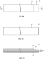
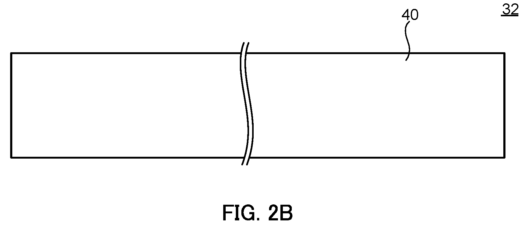
- FIGS. 2A to 2C schematically illustrate band-shaped negative electrode 32 used in wound body 16 in FIG. 1 .
- FIG. 2A is a plan view of negative electrode 32
- FIG. 2B is a bottom view of negative electrode 32
- FIG. 2C is a cross-sectional view taken along the line 2C-2C of negative electrode 32.
- negative electrode 32 contains negative electrode current collector 38 and negative electrode mixture layer 40.
- Negative electrode current collector 38 is a non-porous current collector, preferably a non-porous metal conductor having a sheet shape, that is, so-called non-porous foil.
- non-porous means that there is no hole extending between the front surface and the back surface of a sheet, and specifically, there is no hole throughout the entire sheet.
- the material of negative electrode current collector 38 may be a metal material that is conductive and stable even at the negative electrode reaction potential, and the examples of the material include copper, copper alloys (for example, brass), and iron, preferably copper. That is, negative electrode current collector 38 is preferably a copper foil.
- the surface of negative electrode current collector 38 may be plated.
- negative electrode current collector 38 includes plating film 38A on the surface thereof (see FIG. 1 ).
- the metal of plating film 38A is a metal with a higher hydrogen overvoltage than the metal of the main body of negative electrode current collector 38, preferably a metal with a further higher hydrogen overvoltage, and more preferably a metal with a higher hydrogen overvoltage than copper, for example, tin.
- the presence of plating film 38A can inhibit local cell reactions between negative electrode current collector 38 and outer can 12 even when the electrolyte seeps into the outermost peripheral portion of wound body 16 or zinc dissolves therein, thereby further reducing self-discharge.
- the thickness of negative electrode current collector 38 is not particularly limited, but is, for example, 20 to 65 ⁇ m. By setting the thickness of negative electrode current collector 38 to 20 ⁇ m or more, defects of the negative electrode current collector 38, for example, at the outermost peripheral portion, caused by deformation of negative electrode mixture layer 40 disposed on the surface opposite the inner wall surface of outer can 12 during charge and discharge can be further reduced. By setting the thickness of negative electrode current collector 38 to 65 ⁇ m or less, the amount of the negative electrode mixture filled in outer can 12 can be made less likely to decrease.
- Negative electrode mixture layers 40 are disposed on the surfaces on both sides of negative electrode current collector 38, respectively (see FIG. 2C ). As described above, negative electrode 32 is disposed on the outermost peripheral surface when wound body 16 is formed. Negative electrode 32 includes, in a portion thereof located at the outermost peripheral surface, current collector exposed portion 42 where the negative electrode mixture layer 40 is not disposed (see FIG. 2A ).
- Current collector exposed portion 42 is a portion where the surface of negative electrode current collector 38 (the surface of plating film 38A in the present embodiment) is exposed and where no resin coating film or the like is disposed.
- Current collector exposed portion 42 is provided in a portion located at outermost peripheral surface when wrapped around, and may be provided only in a portion of the outermost peripheral surface of wound body 16 or on the entire outermost peripheral surface. From the viewpoint of further reducing the self-discharge, current collector exposed portion 42 is provided at least in a portion (for example, 50% or more) and preferably on the entire outermost peripheral surface of wound body 16.
- negative electrode current collector 38 exposed at current collector exposed portion 42 is in direct contact with the inner wall surface of outer can 12.
- the negative electrode mixture of negative electrode mixture layer 40 contains a negative electrode active material.
- the negative electrode active material contains at least one of zinc, a zinc alloy, and a zinc-containing compound.
- the metal of the zinc alloy include bismuth, aluminum, and indium, in addition to zinc.
- the zinc-containing compound include zinc oxides (grade 1/ grade 2/ grade 3), zinc hydroxide, zinc sulfides, tetrahydroxyzinc ion salts, zinc halides, zinc carboxylate compounds such as zinc acetate, zinc tartrate, and zinc oxalate, zinc magnesium, calcium zincate, barium zincate, zinc borate, zinc silicate, zinc aluminate, zinc fluoride, zinc carbonate, zinc hydrogen carbonate, zinc nitrate, and zinc sulfate.
- the negative electrode active material preferably contains zinc oxide, and more preferably contains zinc oxide and zinc. This inclusion of zinc not only allows zinc to function as a discharge reserve, for example, but also may further reduce the internal resistance of zinc battery due to its lower resistance.
- the negative electrode active material is, for example, in the form of a powder.
- the particle size of the particles of negative electrode active material is not particularly limited, but when zinc or a zinc alloy is used, the average particle size is preferably 10 to 1000 ⁇ m, and when a zinc-containing compound is used, it is preferably 0.1 to 100 ⁇ m.
- the average particle size means average particle size at which the cumulative value by mass is 50%, and is measured by a laser diffraction/scattering method using a particle size distribution measuring apparatus.
- the negative electrode mixture may further contain a negative electrode additive and/or a binder in addition to the negative electrode active material.
- the negative electrode additive improves the characteristics of the negative electrode, specifically, reduces the elution of the negative electrode active material into the electrolyte
- examples of the negative electrode additive include bismuth oxide, bismuth hydroxide, indium oxide, indium hydroxide, potassium oxalate, and hydrates thereof.
- the potassium oxalate and/or the hydrate thereof dissociates into oxalate ions.
- the binder has a function of binding a negative electrode active material and a negative electrode additive to each other and further has a function of binding the negative electrode active material, the negative electrode additive, and the like to a negative electrode current collector.
- the binder include hydroxypropyl cellulose, carboxymethyl cellulose, polyvinyl alcohol, polyvinylpyrrolidone, polyacrylic acid, sodium polyacrylate, polyimide, polyamideimide, polyamide, styrene-butadiene rubber, polyethylene oxide, polytetrafluoroethylene, polyvinylidene fluoride, perfluoroalkoxy fluorine resin, and copolymers of tetrafluoroethylene and hexafluoropropylene.
- a styrene-butadiene rubber is preferable from the viewpoints that the rubber has a high binding effect and an alkali resistance.
- a non-porous current collector is used as negative electrode current collector 38 in the present invention, and thus it is difficult to obtain adhesion between the negative electrode mixture and the current collector as compared to a porous current collector. Even in such cases, by using the styrene-butadiene rubber as the binder, a satisfactory binding property is more likely to be obtained even for a non-porous current collector.
- the content of the binder may be any value such that negative electrode mixture layer 40 can be sufficiently bound to negative electrode current collector 38, but in the case of the styrene-butadiene rubber, for example, the content may be 1 to 5% by mass, preferably 1 to 3% by mass, based on the total amount of negative electrode mixture.
- separator 34 is disposed between positive electrode 30 and negative electrode 32 (see FIG. 1 ).
- separator 34 include nonwoven fabric separators and dendrite-resistant separators.
- nonwoven fabric separators examples include separators obtained by adding hydrophilic functional groups to nonwoven fabrics made of polyamide fibers, and separators obtained by adding hydrophilic functional groups to nonwoven fabrics made of polyolefin fibers such as polyethylene or polypropylene.
- polyolefin fiber nonwoven fabrics to which sulfonation treatment has been applied to add sulfonic groups are preferred.
- the sulfonic groups are added by treating nonwoven fabrics with acid containing sulfonic groups, such as sulfuric acid or fuming sulfuric acid. Batteries using separators containing fibers having such sulfonic groups are more likely to reduce self-discharge.
- dendrite-resistant separators examples include polyolefin-based microporous films, such as polyethylene or polypropylene.
- separator 34 One type or a combination of two or more types of separator 34 may be used.
- separator 34 a laminate of a nonwoven fabric separator and a dendrite-resistant separator (preferably obtained by subjecting a polyolefin-based microporous film to a hydrophilization treatment) may be used.
- the above zinc battery 10 includes, as an electrode group, wound body 16 in which positive electrode 30 and negative electrode 32 are stacked with a separator 34 therebetween and wound.
- Negative electrode 32 is disposed on the outermost peripheral surface of the wound body 16; negative electrode 32 includes, in the portion thereof located at the outermost peripheral surface, current collector exposed portion 42 where the negative electrode mixture layer 40 is not disposed and the negative electrode current collector 38 is exposed.
- This configuration can reduce the elution of zinc ions from negative electrode mixture layer 40 in contact with the inner wall surface of outer can 12, and can reduce local cell reactions between negative electrode 32 and the inner wall surface of outer can 12, thereby reducing the self-discharge.
- a predetermined plating film 12B is disposed on inner wall surface of outer can 12. Even when plating film 12B contains a metal having a not very high in hydrogen overvoltage, such as nickel, the self-discharge can be highly reduced by providing current collector exposed portion 42.
- plating film 38A containing a metal having a relatively high hydrogen overvoltage is disposed on the surface of negative electrode current collector 38. This configuration makes it possible to further reduce local cell reactions even in the vicinity of the negative electrode current collector 38, thereby further reducing the self-discharge.
- the above zinc battery can be manufactured by any method.
- a zinc battery can be manufactured through the following steps: 1) preparing electrodes (positive electrode and negative electrode); and 2) obtaining a zinc battery by using the prepared electrodes.
- electrodes positive electrode and negative electrode
- an active material and an optional additive and/or binder are mixed or kneaded with a solvent (for example, water) to obtain a mixture slurry. Then, the mixture slurry is applied on or allows to fill a current collector, dried, and further rolled as needed to form a mixture layer. Such rolling increases the packing density of the active material in the mixture layer.
- a solvent for example, water
- positive electrode 30 can be manufactured as follows.
- a positive electrode active material powder, a positive electrode additive, a binder, and water are mixed and kneaded to prepare positive electrode mixture slurry.
- the obtained positive electrode mixture slurry is allowed to fill, for example, nickel foam (current collector), and then dried and rolled to form a positive electrode mixture layer.
- the obtained positive electrode sheet is then cut to a predetermined size to obtain positive electrode 30.
- negative electrode 32 can be manufactured as follows.
- a negative electrode active material powder, a negative electrode additive, a binder, and water are kneaded to prepare a negative electrode mixture.
- the obtained negative electrode mixture slurry is applied to the surfaces on both sides of a negative electrode current collector. At this time, the negative electrode mixture slurry is not applied to a portion (of the negative electrode current collector) which would be located on the outermost peripheral surface when the wound body is formed. Then, the negative electrode mixture slurry coated on the negative electrode current collector is dried and then rolled to form a negative electrode mixture layer. The obtained negative electrode sheet is then cut to a predetermined size to obtain negative electrode 32.
- a zinc battery is produced by using the prepared electrodes.
- a wound body is produced in which the prepared positive electrode 30 and negative electrode 32 are wound in a stacked state with separator 34 therebetween.
- Positive electrode lead 36 is welded to one end of positive electrode 30 in the longitudinal direction of the positive electrode.
- separator 34, positive electrode 30, separator 34, and negative electrode 32 are stacked in this order and wound along the longitudinal direction such that negative electrode 32 is located on the outside, thereby obtaining wound body 16.
- activation processing is performed by charging the battery under the predetermined condition.
- the activation condition can be adjusted according to the characteristics of the electrode active materials (positive electrode active material and negative electrode active material). Zinc battery 10 thus can be obtained.
- outer can 12 has a cylindrical shape as an example, but the shape is not limited to cylindrical and may have a prismatic shape.
- plating film 12B is disposed on the inner wall surface of outer can 12 and plating film 38A is disposed on the surface of negative electrode current collector 38 as an example, but these can be omitted.
- a nickel zinc battery (for example, a nickel zinc secondary battery) was described as an example of a zinc battery, but the battery is not limited to the nickel zinc battery, and may also be an air zinc battery (for example, an air zinc secondary battery), a silver-zinc battery (for example, a silver-zinc secondary battery), or the like.
- Nickel sulfate, zinc sulfate, and cobalt sulfate were weighed out so that the amount of zinc was 4.0 parts by mass and the amount of cobalt became 1.0 parts by mass based on 100 parts by mass of nickel hydroxide, and weighed substances were added to 1 mol/L of an aqueous sodium hydroxide solution containing ammonium ions, thereby preparing a mixed aqueous solution. While stirring the obtained mixed aqueous solution, 1mol/L of an aqueous sodium hydroxide solution was gradually added to the mixed aqueous solution to cause a reaction, and the pH during the reaction was stabilized at 11 to obtain base particles mainly composed of nickel hydroxide with solid-solubilized Zn and Co.
- the obtained base particles were washed 3 times with 10 times the amount of pure water, and then subjected to dehydration and drying treatment.
- the particle size of the obtained base particles was measured using a laser diffraction/scattering type particle size distribution measuring apparatus, and the average particle size at which the cumulative value by mass is 50% was 8 ⁇ m.
- the obtained base particles were charged into an aqueous cobalt sulfate solution, and while stirring this aqueous cobalt sulfate solution, 1mol/L of an aqueous sodium hydroxide solution was gradually dropped to cause a reaction, and the pH during the reaction was maintained at 11 to obtain a precipitate. The precipitate formed was then filtered off, washed with pure water, and then vacuum dried. As a result, intermediate product particles including a layer containing 5% by mass of cobalt hydroxide on the surface of the base particles was obtained. The thickness of the cobalt hydroxide layer was approximately 0.1 ⁇ m.
- the intermediate product particles were then charged into 25% by mass of an aqueous sodium hydroxide solution.
- P is defined as the mass of the aggregate of the intermediate product particles
- Q is defined as the mass of the aqueous sodium hydroxide solution
- the ratio of the masses namely P:Q was set to be 1:10.
- the aqueous sodium hydroxide solution to which the intermediate product powder had been added was subjected to heat treatment in which the temperature was kept constant at 85°C for 8 hours while the aqueous sodium hydroxide solution is stirred.
- the intermediate product particles subjected to the heat treatment were washed with pure water and dried by applying hot air at 65°C.
- an aggregate of positive electrode active material particles positive electrode active material powder
- a surface layer containing highly-ordered cobalt oxide is on the surface of base particles including Zn and Co solid-solubilized therein, were obtained.
- the positive electrode active material slurry was allowed to fill a sheet-shaped nickel foam (current collector) having an areal density (weight per unit area) of approximately 350 g/m 2 , a porosity of 95%, and a thickness of 1.3 mm, and then dried and rolled. The resultant was then cut to a predetermined size to produce a nickel positive electrode plate with a capacity of 2000 mAh per sheet.
- a negative electrode active material slurry was produced by mixing 100 parts by mass of zinc oxide powder, 25 parts by mass of zinc alloy powder, 3 parts by mass of bismuth oxide powder, 0.1 parts by mass of indium oxide powder, 2 parts by mass of potassium oxalate monohydrate powder, 1 parts by mass of hydroxypropyl cellulose powder, 8 parts by mass of styrene-butadiene rubber aqueous dispersion (50% solution), and 100 parts by mass of water.
- the negative active material slurry was applied to both surfaces of a 38 ⁇ m thick non-porous copper foil (current collector) with tin-plating on its surface. During the application of the slurry, the slurry was applied on the entire surface of the non-porous foil on one side, and on the other side, the slurry was applied only on a portion that faces positive electrode but not applied to a portion that is located on the outermost peripheral surface of the wound body (the outermost peripheral surface that contacts the inner wall surface of the outer can), thereby exposing the negative electrode current collector. After drying, the electrode plate was rolled with a rolling roll. The resultant was then cut to a predetermined size to produce a zinc negative electrode plate with a capacity of 4500 mAh per sheet.
- An aqueous solution containing an alkali-metal hydroxide as a solute and saturated with zinc oxide was prepared to obtain an alkali electrolyte.
- the alkaline electrolyte was a mixed solution of KOH and LiOH, and had a mass ratio namely KOH:LiOH of 6:0.5 and a specific gravity of 1.31.
- the positive electrode plate and negative electrode plate prepared above were wound together with a nonwoven fabric separator and a dendrite-resistant separator (polyolefin-based microporous membrane). Specifically, a laminate (in which the above components were stacked in the order of non-woven separator and dendrite resistant separator/positive electrode plate/non-woven separator and dendrite resistant separator/negative electrode plate) was wound. As a result, a wound body was obtained in which the positive and negative plates were wound in a stacked state with the separator therebetween, and the negative plate was disposed at the outermost peripheral surface.
- the obtained wound body was housed in a cylindrical outer can (made of iron) with nickel plating applied to the inner wall surface of the outer can.
- a predetermined amount of the electrolyte prepared above was poured into the outer can to produce a cylindrical nickel zinc battery with a nominal capacity of 2000 mAh.
- the obtained battery was charged to 100% of the nominal capacity followed by one cycle to discharge to 1.3V for activation.
- a zinc negative electrode plate was produced in the same manner as in Example 1, except that, during the application of the slurry, the slurry was applied to the entire surface of the non-porous foil on one side and also to the entire surface of the non-porous foil on the other side.
- a cylindrical shape nickel zinc battery was produced in the same manner as in Example 1 except that the negative electrode plate prepared above was used.
- the residual rate of discharge capacity was determined for the batteries produced above by the following methods.
- the nickel zinc battery was charged again to 100% of the nominal capacity, and left for one month in an environment of 35°C, after which the battery was discharged to 1.3 V, and the discharge capacity at that time was used as the residual capacity [B].
- Residual rate % Residual capacity B / Initial capacity A ⁇ 100
- Example 1 including a current collector exposed portion has a significantly higher residual rate of discharge capacity than the battery in Comparative example 1 including no current collector exposed portion. From the result, it can be seen that the self-discharge is reduced by providing a current collector exposed portion.
- a cylindrical nickel zinc battery was produced in the same manner as in Example 1, except that the obtained wound body was housed in a cylindrical outer can having a tin-plated inner wall surface.
- a cylindrical nickel zinc battery was produced in the same manner as in Comparative example 1, except that the obtained wound body was housed in the cylindrical outer can having a tin-plated inner wall surface.
- Example 2 including a current collector exposed portion has a significantly higher residual rate of discharge capacity than the battery in Comparative example 2 including no current collector exposed portion.
- the present invention can provide a negative electrode for a zinc battery and a zinc battery both capable of reducing self-discharge as compared with the related art.
Landscapes
- Chemical & Material Sciences (AREA)
- Chemical Kinetics & Catalysis (AREA)
- Electrochemistry (AREA)
- General Chemical & Material Sciences (AREA)
- Engineering & Computer Science (AREA)
- Manufacturing & Machinery (AREA)
- Materials Engineering (AREA)
- Inorganic Chemistry (AREA)
- Battery Electrode And Active Subsutance (AREA)
- Secondary Cells (AREA)
Abstract
This negative electrode for a zinc battery comprises a nonporous current collector and a negative electrode mixture layer which is held by the current collector and contains at least one of zinc, a zinc alloy, and a zinc-containing compound. The negative electrode has a current collector-exposed section in which the negative electrode mixture layer is not disposed, in a portion located at the outermost circumferential surface when wound.
Description
- The present invention relates to a negative electrode for a zinc battery and a zinc battery.
- A zinc battery is a battery that uses zinc, zinc alloys or zinc-containing compounds in negative active materials. Examples of the battery using zinc or the like as a negative electrode active material include a primary battery and a secondary battery, and, for example, the following are known: an air zinc battery using oxygen in the air as a positive electrode active material, a nickel zinc battery using a nickel-containing compound as a positive electrode active material, a manganese zinc battery and a zinc-ion battery using a manganese-containing compound as a positive electrode active material, and a silver zinc battery using a silver-containing compound as a positive electrode active material.
- Among these, the nickel zinc battery is a water-based battery that uses water-based electrolyte and is therefore safer than a non-water-based battery. Further, the combination of the zinc electrode and a nickel electrode has a high electromotive force as a water-based battery, thus the nickel zinc battery is also relatively inexpensive. Therefore, nickel zinc batteries are studied to be applied to industrial applications (for example, applications such as backup power sources) and automotive applications (for example, applications such as hybrid vehicles).
- For example, PTL 1 discloses an alkaline zinc storage battery including a wound body in which a positive electrode containing nickel hydroxide or the like and a negative electrode containing a zinc oxide, a metal zinc, or the like are wound in a stacked state with a separator therebetween, and an outer can for housing the wound body. The negative electrode is disposed at the outermost peripheral surface of the wound body.
- PTL 1
Japanese Patent Application Laid-Open No. S53-071234 - The zinc battery described in PTL 1 could not have sufficiently reduced self-discharge. That is, metallic zinc, which is the negative electrode active material of the negative electrode located at the outermost peripheral portion of the wound body, is spontaneously dissolved by contacting with an electrolyte. The generated electrons then moved to the outer can, and a local cell reaction occurred between the negative electrode active material and the inner wall surface of the outer can, which made self-discharge more likely to occur.
- The present invention has been made based on the above-described circumstances, and an object thereof is to provide a negative electrode for a zinc battery and a zinc battery both capable of reducing self-discharge as compared with the related art.
- The present invention provides a negative electrode for a zinc battery, the negative electrode being wound with a positive electrode in a stacked state with a separator therebetween, and housed within an outer can, the negative electrode including: a current collector that is non-porous; and a negative electrode mixture layer held by the current collector and containing at least one of zinc, a zinc alloy, and a zinc-containing compound, in which
the negative electrode includes, in a portion thereof that is located at an outermost peripheral surface when the negative electrode is wound, a current collector exposed portion where the negative electrode mixture layer is not disposed and the current collector is exposed. - The present invention provides a zinc battery, including: a wound body in which a negative electrode and a positive electrode are wound in a stacked state with a separator therebetween; and an outer can that houses the wound body, in which
the negative electrode includes a current collector that is non-porous, and a negative electrode mixture layer held by the current collector and containing at least one of zinc, a zinc alloy, and a zinc-containing compound; the negative electrode is disposed on an outermost peripheral surface of the wound body; and the negative electrode includes, in a portion thereof that is located at the outermost peripheral surface, a current collector exposed portion where the negative electrode mixture layer is not disposed and the current collector is exposed. - The present invention can provide a negative electrode for a zinc battery and a zinc battery both capable of reducing self-discharge as compared with the related art.
-
-
FIG. 1 is a partially cutaway perspective view illustrating a zinc battery according to an embodiment of the present invention; and -
FIGS. 2A to 2C schematically illustrate a configuration of a negative electrode used in the zinc battery inFIG. 1 . - As an exemplary zinc battery according to the embodiment, a nickel zinc battery will be described below.
-
FIG. 1 is a partially cutaway perspective view illustratingzinc battery 10 according to an embodiment of the present invention. InFIG. 1 , some portions ofwound body 16 are omitted. In addition, the areas enclosed by the dashed dotted line illustrate enlarged cross-section of the areas. - As illustrated in
FIG. 1 ,zinc battery 10 according to the embodiment is a cylindrical battery of FA size, and includesouter can 12, sealingbody 14, wound body 16 (electrode group), an electrolyte (not illustrated),upper insulation member 18, andlower insulation member 20. - Outer can 12 is a container that houses wound
body 16, and, in the present embodiment, is a container having a bottom and a cylindrical shape with an open upper end. Outer can 12 is conductive, andbottom wall 12A thereof functions as a negative electrode terminal. - The material of
outer can 12 may be a conductive material having corrosion resistance to an electrolyte or an electrochemical reaction inside of the battery, and usually includes a metal material such as iron or steel. The inner wall surface ofouter can 12 is preferably plated. In the present embodiment, the inner wall surface ofouter can 12 includesplating film 12B. The metal of platingfilm 12B has a higher hydrogen overvoltage than the metal of the main body ofouter can 12, and preferably has a higher hydrogen overvoltage than iron or steel. Examples of such a metal include nickel, tin, copper, indium, and bismuth. Among these, tin is preferable from the viewpoint of further reducing self-discharge. Although nickel does not exhibit a hydrogen overvoltage as high as tin, by adopting the configuration of the present invention, self-discharge can be satisfactorily reduced even when nickel is used. - Sealing
body 14 is fixed to the opening ofouter can 12 via insulation packing 22, and sealsouter can 12 while providing a positive electrode terminal. Sealingbody 14 includeslid plate 24,valve body 26, andpositive electrode terminal 28. -
Lid plate 24 is a conductive member having a disk shape and includes through-hole 24A at the center thereof. Insulation packing 22 has a ring shape surroundinglid plate 24, and is interposed betweenouter can 12 and sealingbody 14. Insulation packing 22 is fixed to openingedge 12C ofouter can 12 by crimpingopening edge 12C ofouter can 12. Thus,lid plate 24 and insulation packing 22 cooperate with each other to hermetically close the opening ofouter can 12. -
Valve body 26 is a member made of rubber, and is disposed on the outer surface oflid plate 24 so as to block through-hole 24A. -
Positive electrode terminal 28 is a metal member having a cylindrical shape with a flange, and is electrically connected to the outer surface oflid plate 24 to covervalve body 26.Positive electrode terminal 28presses valve body 26 towardlid plate 24. A gas vent hole (not illustrated) is opened topositive electrode terminal 28. - Further, in the normal operation, through-
hole 24A is hermetically closed byvalve body 26. When gas is generated withinouter can 12 and the inner pressure thereof increases, on the other hand,valve body 26 is compressed by the inner pressure to open through-hole 24A, and as a result, the gas is released to the outside from the inside ofouter can 12 through through-hole 24A and a gas vent hole (not illustrated) ofpositive electrode terminal 28. That is, through-hole 24A,valve body 26, andpositive electrode terminal 28 form a safety valve for the battery. -
Wound body 16 is an electrode group housed withinouter can 12 and includingpositive electrode 30,negative electrode 32, andseparator 34. Specifically, woundbody 16 is an electrode group in whichpositive electrode 30 andnegative electrode 32 are wound in a stacked state withseparator 34 therebetween. More specifically, woundbody 16 obtained by winding a laminate ofseparator 34,positive electrode 30,separator 34, andnegative electrode 32 such thatnegative electrode 32 is on the outside. -
Negative electrode 32 is disposed on the outermost peripheral surface ofwound body 16, andnegative electrode 32 is in contact with an inner wall surface ofouter can 12. That is,negative electrode 32 andouter can 12, which is a negative electrode terminal, are electrically connected to each other. In the present embodiment,negative electrode 32 located on the outermost peripheral surface of wound body 16 (specifically, negative electrodecurrent collector 38 exposed at current collector exposedportion 42 described below) is in direct contact with the inner wall surface ofouter can 12; however the configuration is not limited thereto. A conductive member such as a metal sheet may be disposed betweennegative electrode 32 located on the outermost peripheral surface and the inner wall surface ofouter can 12. However, from the viewpoint of reducing the internal resistance, no insulating coating film or insulating member is disposed betweennegative electrode 32 located on the outermost peripheral surface and the inner wall surface ofouter can 12. - Meanwhile,
positive electrode lead 36 is connected topositive electrode 30 ofwound body 16. One end ofpositive electrode lead 36 is connected topositive electrode 30, and the other end ofpositive electrode lead 36 is connected tolid plate 24. Thus,positive electrode 30 andpositive electrode terminal 28 are electrically connected to each other viapositive electrode lead 36 andlid plate 24. -
Upper insulation member 18 is disposed betweenwound body 16 andlid plate 24. Thus,negative electrode 32 ofwound body 16 does not contact sealingbody 14. Further,upper insulation member 18 includes slit 18A, andpositive electrode lead 36 passes throughslit 18A. -
Lower insulation member 20 is disposed betweenwound body 16 and the bottom ofouter can 12. Thus,positive electrode 30 ofwound body 16 does not contact the inner wall surface ofouter can 12. - The electrolyte (not illustrated) is alkaline electrolyte and is sealed in an
outer can 12.Wound body 16 is impregnated with the alkaline electrolyte, andseparator 34 mainly holds the alkaline electrolyte. - The alkaline electrolyte is preferably an aqueous solution containing at least one of KOH, NaOH and LiOH as a solute. The concentration of the alkaline electrolyte (solute concentration) is not particularly limited, but may be, for example, approximately 7N (approximately 30% by mass). In addition, in the present embodiment, it is preferable that the alkaline electrolyte is obtained by dissolving zinc oxide to a saturated concentration. This is to reduce the dissolution of zinc-ion from negative electrode to the electrolyte as much as possible.
- In the following, each member in
wound body 16 will be described. -
Positive electrode 30 includes a positive electrode current collector and a positive electrode mixture. - The positive electrode current collector may be a non-porous or porous current collector. The porous current collector is, for example, a current collector with a porous structure and is preferably a metallic body with a three-dimensional mesh-shaped skeleton. The skeleton of the metallic body spreads over the entire positive electrode collector, and the gaps in this skeleton form communicating holes. The communicating holes are filled with the positive electrode mixture. The material of the positive electrode current collector may be a metal material that is conductive and stable even at the positive electrode reaction potential, and is preferably nickel. That is, the positive electrode current collector may be nickel foam or a mesh-shaped, sponge-shaped, or fiber-shaped metal body made of nickel or subjected to nickel plating.
- The positive electrode mixture is held by the positive electrode current collector and contains a positive electrode active material.
- The positive electrode active material may be nickel hydroxide. The nickel hydroxide may be in the form of, for example, powder. The nickel hydroxide particles are preferably high-order nickel hydroxide particles. The nickel hydroxide particles preferably contain solid-solubilized Co, Zn, Cd, or the like.
- Further, the nickel hydroxide particles are preferably covered with a surface layer containing a cobalt compound. The surface layer is preferably a high-order cobalt compound layer containing a cobalt compound having a valence of three or more. Examples of the cobalt compound having a valence of three or more include cobalt oxyhydroxide (CoOOH) having a valence of three or more. This is because a high-order cobalt compound layer containing such a high-order cobalt compound has excellent electrical conductivity and forms a conductive network.
- The positive electrode mixture may further include a positive electrode additive and/or a binder in addition to the positive electrode active material.
- Examples of the positive electrode additive include yttrium oxide; cobalt compounds such as cobalt oxide, cobalt metal, and cobalt hydroxide; zinc compounds such as metal zinc, zinc oxide, and zinc hydroxide; rare earth compounds such as erbium oxide; and niobium oxide.
- The binder has a function of binding a positive electrode active material and a positive electrode additive to each other and of binding the positive electrode active material and the positive electrode additive to a positive electrode current collector. The binder may be a hydrophilic or hydrophobic polymer, and examples the binder include hydroxypropyl cellulose, carboxymethyl cellulose, sodium polyacrylate, and fluorine-based polymers (such as polytetrafluoroethylene (PTFE).
-
FIGS. 2A to 2C schematically illustrate band-shapednegative electrode 32 used inwound body 16 inFIG. 1 . InFIG. 2A to 2C, FIG. 2A is a plan view ofnegative electrode 32,FIG. 2B is a bottom view ofnegative electrode 32, andFIG. 2C is a cross-sectional view taken along theline 2C-2C ofnegative electrode 32. - As illustrated in
FIG. 2A to 2C ,negative electrode 32 contains negative electrodecurrent collector 38 and negativeelectrode mixture layer 40. - Negative electrode
current collector 38 is a non-porous current collector, preferably a non-porous metal conductor having a sheet shape, that is, so-called non-porous foil. Herein, the term "non-porous" means that there is no hole extending between the front surface and the back surface of a sheet, and specifically, there is no hole throughout the entire sheet. The material of negative electrodecurrent collector 38 may be a metal material that is conductive and stable even at the negative electrode reaction potential, and the examples of the material include copper, copper alloys (for example, brass), and iron, preferably copper. That is, negative electrodecurrent collector 38 is preferably a copper foil. - The surface of negative electrode
current collector 38 may be plated. In the present embodiment, negative electrodecurrent collector 38 includesplating film 38A on the surface thereof (seeFIG. 1 ). The metal of platingfilm 38A is a metal with a higher hydrogen overvoltage than the metal of the main body of negative electrodecurrent collector 38, preferably a metal with a further higher hydrogen overvoltage, and more preferably a metal with a higher hydrogen overvoltage than copper, for example, tin. The presence of platingfilm 38A can inhibit local cell reactions between negative electrodecurrent collector 38 andouter can 12 even when the electrolyte seeps into the outermost peripheral portion ofwound body 16 or zinc dissolves therein, thereby further reducing self-discharge. - The thickness of negative electrode
current collector 38 is not particularly limited, but is, for example, 20 to 65 µm. By setting the thickness of negative electrodecurrent collector 38 to 20 µm or more, defects of the negative electrodecurrent collector 38, for example, at the outermost peripheral portion, caused by deformation of negativeelectrode mixture layer 40 disposed on the surface opposite the inner wall surface ofouter can 12 during charge and discharge can be further reduced. By setting the thickness of negative electrodecurrent collector 38 to 65 µm or less, the amount of the negative electrode mixture filled inouter can 12 can be made less likely to decrease. - Negative electrode mixture layers 40 are disposed on the surfaces on both sides of negative electrode
current collector 38, respectively (seeFIG. 2C ). As described above,negative electrode 32 is disposed on the outermost peripheral surface when woundbody 16 is formed.Negative electrode 32 includes, in a portion thereof located at the outermost peripheral surface, current collector exposedportion 42 where the negativeelectrode mixture layer 40 is not disposed (seeFIG. 2A ). - Current collector exposed
portion 42 is a portion where the surface of negative electrode current collector 38 (the surface of platingfilm 38A in the present embodiment) is exposed and where no resin coating film or the like is disposed. Current collector exposedportion 42 is provided in a portion located at outermost peripheral surface when wrapped around, and may be provided only in a portion of the outermost peripheral surface ofwound body 16 or on the entire outermost peripheral surface. From the viewpoint of further reducing the self-discharge, current collector exposedportion 42 is provided at least in a portion (for example, 50% or more) and preferably on the entire outermost peripheral surface ofwound body 16. In the present embodiment, negative electrodecurrent collector 38 exposed at current collector exposedportion 42 is in direct contact with the inner wall surface ofouter can 12. - The negative electrode mixture of negative
electrode mixture layer 40 contains a negative electrode active material. - The negative electrode active material contains at least one of zinc, a zinc alloy, and a zinc-containing compound. Examples of the metal of the zinc alloy include bismuth, aluminum, and indium, in addition to zinc. Examples of the zinc-containing compound include zinc oxides (grade 1/ grade 2/ grade 3), zinc hydroxide, zinc sulfides, tetrahydroxyzinc ion salts, zinc halides, zinc carboxylate compounds such as zinc acetate, zinc tartrate, and zinc oxalate, zinc magnesium, calcium zincate, barium zincate, zinc borate, zinc silicate, zinc aluminate, zinc fluoride, zinc carbonate, zinc hydrogen carbonate, zinc nitrate, and zinc sulfate. Among them, the negative electrode active material preferably contains zinc oxide, and more preferably contains zinc oxide and zinc. This inclusion of zinc not only allows zinc to function as a discharge reserve, for example, but also may further reduce the internal resistance of zinc battery due to its lower resistance.
- The negative electrode active material is, for example, in the form of a powder. The particle size of the particles of negative electrode active material is not particularly limited, but when zinc or a zinc alloy is used, the average particle size is preferably 10 to 1000 µm, and when a zinc-containing compound is used, it is preferably 0.1 to 100 µm. The average particle size means average particle size at which the cumulative value by mass is 50%, and is measured by a laser diffraction/scattering method using a particle size distribution measuring apparatus.
- The negative electrode mixture may further contain a negative electrode additive and/or a binder in addition to the negative electrode active material.
- The negative electrode additive improves the characteristics of the negative electrode, specifically, reduces the elution of the negative electrode active material into the electrolyte, and examples of the negative electrode additive include bismuth oxide, bismuth hydroxide, indium oxide, indium hydroxide, potassium oxalate, and hydrates thereof. For example, when potassium oxalate and/or a hydrate thereof is eluted into the electrolyte, the potassium oxalate and/or the hydrate thereof dissociates into oxalate ions. As a result, zinc ions eluted in the electrolyte forms a poorly soluble salt with the oxalate ions, and the poorly soluble salt covers the surface of the negative electrode active material, thereby reducing the contact between the metallic zinc of the negative electrode active material and the electrolyte. Therefore, the self-discharge is less likely to occur.
- The binder has a function of binding a negative electrode active material and a negative electrode additive to each other and further has a function of binding the negative electrode active material, the negative electrode additive, and the like to a negative electrode current collector. Examples of the binder include hydroxypropyl cellulose, carboxymethyl cellulose, polyvinyl alcohol, polyvinylpyrrolidone, polyacrylic acid, sodium polyacrylate, polyimide, polyamideimide, polyamide, styrene-butadiene rubber, polyethylene oxide, polytetrafluoroethylene, polyvinylidene fluoride, perfluoroalkoxy fluorine resin, and copolymers of tetrafluoroethylene and hexafluoropropylene.
- Among them, a styrene-butadiene rubber is preferable from the viewpoints that the rubber has a high binding effect and an alkali resistance. In particular, a non-porous current collector is used as negative electrode
current collector 38 in the present invention, and thus it is difficult to obtain adhesion between the negative electrode mixture and the current collector as compared to a porous current collector. Even in such cases, by using the styrene-butadiene rubber as the binder, a satisfactory binding property is more likely to be obtained even for a non-porous current collector. - The content of the binder may be any value such that negative
electrode mixture layer 40 can be sufficiently bound to negative electrodecurrent collector 38, but in the case of the styrene-butadiene rubber, for example, the content may be 1 to 5% by mass, preferably 1 to 3% by mass, based on the total amount of negative electrode mixture. - As described above,
separator 34 is disposed betweenpositive electrode 30 and negative electrode 32 (seeFIG. 1 ). Examples ofseparator 34 include nonwoven fabric separators and dendrite-resistant separators. - Examples of the nonwoven fabric separators include separators obtained by adding hydrophilic functional groups to nonwoven fabrics made of polyamide fibers, and separators obtained by adding hydrophilic functional groups to nonwoven fabrics made of polyolefin fibers such as polyethylene or polypropylene. Among these, polyolefin fiber nonwoven fabrics to which sulfonation treatment has been applied to add sulfonic groups are preferred. The sulfonic groups are added by treating nonwoven fabrics with acid containing sulfonic groups, such as sulfuric acid or fuming sulfuric acid. Batteries using separators containing fibers having such sulfonic groups are more likely to reduce self-discharge.
- Examples of the dendrite-resistant separators include polyolefin-based microporous films, such as polyethylene or polypropylene.
- One type or a combination of two or more types of
separator 34 may be used. For example, asseparator 34, a laminate of a nonwoven fabric separator and a dendrite-resistant separator (preferably obtained by subjecting a polyolefin-based microporous film to a hydrophilization treatment) may be used. - Next, the action of
zinc battery 10 according to the embodiment will be described. - The
above zinc battery 10 includes, as an electrode group, woundbody 16 in whichpositive electrode 30 andnegative electrode 32 are stacked with aseparator 34 therebetween and wound.Negative electrode 32 is disposed on the outermost peripheral surface of thewound body 16;negative electrode 32 includes, in the portion thereof located at the outermost peripheral surface, current collector exposedportion 42 where the negativeelectrode mixture layer 40 is not disposed and the negative electrodecurrent collector 38 is exposed. - This configuration can reduce the elution of zinc ions from negative
electrode mixture layer 40 in contact with the inner wall surface ofouter can 12, and can reduce local cell reactions betweennegative electrode 32 and the inner wall surface ofouter can 12, thereby reducing the self-discharge. - In particular, in the above embodiment, a
predetermined plating film 12B is disposed on inner wall surface ofouter can 12. Even when platingfilm 12B contains a metal having a not very high in hydrogen overvoltage, such as nickel, the self-discharge can be highly reduced by providing current collector exposedportion 42. - In addition, plating
film 38A containing a metal having a relatively high hydrogen overvoltage is disposed on the surface of negative electrodecurrent collector 38. This configuration makes it possible to further reduce local cell reactions even in the vicinity of the negative electrodecurrent collector 38, thereby further reducing the self-discharge. - The above zinc battery can be manufactured by any method. For example, a zinc battery can be manufactured through the following steps: 1) preparing electrodes (positive electrode and negative electrode); and 2) obtaining a zinc battery by using the prepared electrodes.
- In the present step, electrodes (positive electrode and negative electrode) are obtained.
- Specifically, an active material and an optional additive and/or binder are mixed or kneaded with a solvent (for example, water) to obtain a mixture slurry. Then, the mixture slurry is applied on or allows to fill a current collector, dried, and further rolled as needed to form a mixture layer. Such rolling increases the packing density of the active material in the mixture layer.
- For example,
positive electrode 30 can be manufactured as follows. - First, a positive electrode active material powder, a positive electrode additive, a binder, and water are mixed and kneaded to prepare positive electrode mixture slurry. Then, the obtained positive electrode mixture slurry is allowed to fill, for example, nickel foam (current collector), and then dried and rolled to form a positive electrode mixture layer. The obtained positive electrode sheet is then cut to a predetermined size to obtain
positive electrode 30. - For example,
negative electrode 32 can be manufactured as follows. - First, a negative electrode active material powder, a negative electrode additive, a binder, and water are kneaded to prepare a negative electrode mixture. The obtained negative electrode mixture slurry is applied to the surfaces on both sides of a negative electrode current collector. At this time, the negative electrode mixture slurry is not applied to a portion (of the negative electrode current collector) which would be located on the outermost peripheral surface when the wound body is formed. Then, the negative electrode mixture slurry coated on the negative electrode current collector is dried and then rolled to form a negative electrode mixture layer. The obtained negative electrode sheet is then cut to a predetermined size to obtain
negative electrode 32. - In the present step, a zinc battery is produced by using the prepared electrodes.
- Specifically, a wound body is produced in which the prepared
positive electrode 30 andnegative electrode 32 are wound in a stacked state withseparator 34 therebetween.Positive electrode lead 36 is welded to one end ofpositive electrode 30 in the longitudinal direction of the positive electrode. Subsequently, for example,separator 34,positive electrode 30,separator 34, andnegative electrode 32 are stacked in this order and wound along the longitudinal direction such thatnegative electrode 32 is located on the outside, thereby obtainingwound body 16. - After housing obtained wound
body 16 inouter can 12 and injecting the electrolyte intoouter can 12, the opening portion ofouter can 12 is sealed with sealingbody 14. - After leaving the obtained battery for a predetermined time, activation processing is performed by charging the battery under the predetermined condition. The activation condition can be adjusted according to the characteristics of the electrode active materials (positive electrode active material and negative electrode active material).
Zinc battery 10 thus can be obtained. - In the above embodiment,
outer can 12 has a cylindrical shape as an example, but the shape is not limited to cylindrical and may have a prismatic shape. - In the above embodiment, plating
film 12B is disposed on the inner wall surface ofouter can 12 andplating film 38A is disposed on the surface of negative electrodecurrent collector 38 as an example, but these can be omitted. - In addition, in the above embodiment, a nickel zinc battery (for example, a nickel zinc secondary battery) was described as an example of a zinc battery, but the battery is not limited to the nickel zinc battery, and may also be an air zinc battery (for example, an air zinc secondary battery), a silver-zinc battery (for example, a silver-zinc secondary battery), or the like.
- Hereinafter, the invention will be described with reference to Examples. The scope of the present invention is not interpreted to be limited by the Examples.
- Nickel sulfate, zinc sulfate, and cobalt sulfate were weighed out so that the amount of zinc was 4.0 parts by mass and the amount of cobalt became 1.0 parts by mass based on 100 parts by mass of nickel hydroxide, and weighed substances were added to 1 mol/L of an aqueous sodium hydroxide solution containing ammonium ions, thereby preparing a mixed aqueous solution. While stirring the obtained mixed aqueous solution, 1mol/L of an aqueous sodium hydroxide solution was gradually added to the mixed aqueous solution to cause a reaction, and the pH during the reaction was stabilized at 11 to obtain base particles mainly composed of nickel hydroxide with solid-solubilized Zn and Co.
- The obtained base particles were washed 3 times with 10 times the amount of pure water, and then subjected to dehydration and drying treatment. The particle size of the obtained base particles was measured using a laser diffraction/scattering type particle size distribution measuring apparatus, and the average particle size at which the cumulative value by mass is 50% was 8 µm.
- Next, the obtained base particles were charged into an aqueous cobalt sulfate solution, and while stirring this aqueous cobalt sulfate solution, 1mol/L of an aqueous sodium hydroxide solution was gradually dropped to cause a reaction, and the pH during the reaction was maintained at 11 to obtain a precipitate. The precipitate formed was then filtered off, washed with pure water, and then vacuum dried. As a result, intermediate product particles including a layer containing 5% by mass of cobalt hydroxide on the surface of the base particles was obtained. The thickness of the cobalt hydroxide layer was approximately 0.1 µm.
- The intermediate product particles were then charged into 25% by mass of an aqueous sodium hydroxide solution. Here, when P is defined as the mass of the aggregate of the intermediate product particles, and Q is defined as the mass of the aqueous sodium hydroxide solution, the ratio of the masses namely P:Q was set to be 1:10. Then, the aqueous sodium hydroxide solution to which the intermediate product powder had been added was subjected to heat treatment in which the temperature was kept constant at 85°C for 8 hours while the aqueous sodium hydroxide solution is stirred.
- The intermediate product particles subjected to the heat treatment were washed with pure water and dried by applying hot air at 65°C. As a result, an aggregate of positive electrode active material particles (positive electrode active material powder), in which a surface layer containing highly-ordered cobalt oxide is on the surface of base particles including Zn and Co solid-solubilized therein, were obtained.
- To 100 parts by mass of the obtained positive electrode active material powder, 0.5 parts by mass of yttrium oxide powder, 0.3 parts by mass niobium oxide powder, 0.5 parts by mass of zinc oxide powder, and 30.0 parts by mass of water containing 0.2% by mass of hydroxypropylcellulose powder as a binder were added and kneaded to prepare positive electrode mixture slurry.
- The positive electrode active material slurry was allowed to fill a sheet-shaped nickel foam (current collector) having an areal density (weight per unit area) of approximately 350 g/m2, a porosity of 95%, and a thickness of 1.3 mm, and then dried and rolled. The resultant was then cut to a predetermined size to produce a nickel positive electrode plate with a capacity of 2000 mAh per sheet.
- A negative electrode active material slurry was produced by mixing 100 parts by mass of zinc oxide powder, 25 parts by mass of zinc alloy powder, 3 parts by mass of bismuth oxide powder, 0.1 parts by mass of indium oxide powder, 2 parts by mass of potassium oxalate monohydrate powder, 1 parts by mass of hydroxypropyl cellulose powder, 8 parts by mass of styrene-butadiene rubber aqueous dispersion (50% solution), and 100 parts by mass of water.
- The negative active material slurry was applied to both surfaces of a 38 µm thick non-porous copper foil (current collector) with tin-plating on its surface. During the application of the slurry, the slurry was applied on the entire surface of the non-porous foil on one side, and on the other side, the slurry was applied only on a portion that faces positive electrode but not applied to a portion that is located on the outermost peripheral surface of the wound body (the outermost peripheral surface that contacts the inner wall surface of the outer can), thereby exposing the negative electrode current collector. After drying, the electrode plate was rolled with a rolling roll. The resultant was then cut to a predetermined size to produce a zinc negative electrode plate with a capacity of 4500 mAh per sheet.
- An aqueous solution containing an alkali-metal hydroxide as a solute and saturated with zinc oxide was prepared to obtain an alkali electrolyte. The alkaline electrolyte was a mixed solution of KOH and LiOH, and had a mass ratio namely KOH:LiOH of 6:0.5 and a specific gravity of 1.31.
- The positive electrode plate and negative electrode plate prepared above were wound together with a nonwoven fabric separator and a dendrite-resistant separator (polyolefin-based microporous membrane). Specifically, a laminate (in which the above components were stacked in the order of non-woven separator and dendrite resistant separator/positive electrode plate/non-woven separator and dendrite resistant separator/negative electrode plate) was wound. As a result, a wound body was obtained in which the positive and negative plates were wound in a stacked state with the separator therebetween, and the negative plate was disposed at the outermost peripheral surface.
- The obtained wound body was housed in a cylindrical outer can (made of iron) with nickel plating applied to the inner wall surface of the outer can. Next, a predetermined amount of the electrolyte prepared above was poured into the outer can to produce a cylindrical nickel zinc battery with a nominal capacity of 2000 mAh.
- Then, the obtained battery was charged to 100% of the nominal capacity followed by one cycle to discharge to 1.3V for activation.
- A zinc negative electrode plate was produced in the same manner as in Example 1, except that, during the application of the slurry, the slurry was applied to the entire surface of the non-porous foil on one side and also to the entire surface of the non-porous foil on the other side.
- A cylindrical shape nickel zinc battery was produced in the same manner as in Example 1 except that the negative electrode plate prepared above was used.
- The residual rate of discharge capacity was determined for the batteries produced above by the following methods.
- After a nickel zinc battery prepared above was charged to 100% of the nominal capacity, the battery was cycled 3 times to discharge to 1.3V, the discharge capacity at the third cycle was used as the initial discharge capacity [A].
- Next, the nickel zinc battery was charged again to 100% of the nominal capacity, and left for one month in an environment of 35°C, after which the battery was discharged to 1.3 V, and the discharge capacity at that time was used as the residual capacity [B].
- The measured initial discharge capacity [A] and residual capacity [B] were applied to the following equation to calculate the residual rate.

- The evaluation results are shown in Table 1.
[Table 1] Example 1 Comparative example 1 Configuration Current collector exposed portion Yes No Plating type on inner wall surface of outer can Nickel Nickel Evaluation Initial discharge capacity [A] (mAh) 1952 1956 Residual capacity [B] (mAh) 1599 1424 Residual rate [B] / [A] (%) 81.9 72.8 - As shown in Table 1, it can be seen that the battery in Example 1 including a current collector exposed portion has a significantly higher residual rate of discharge capacity than the battery in Comparative example 1 including no current collector exposed portion. From the result, it can be seen that the self-discharge is reduced by providing a current collector exposed portion.
- A cylindrical nickel zinc battery was produced in the same manner as in Example 1, except that the obtained wound body was housed in a cylindrical outer can having a tin-plated inner wall surface.
- A cylindrical nickel zinc battery was produced in the same manner as in Comparative example 1, except that the obtained wound body was housed in the cylindrical outer can having a tin-plated inner wall surface.
- The residual rate of discharge capacity was evaluated in the same manner as described above for the above produced batteries. The evaluation results are shown in Table 2.
[Table 2] Example 2 Comparative example 2 Configuration Current collector exposed portion Yes No Plating type on inner wall surface of outer can Tin Tin Evaluation Initial discharge capacity [A] (mAh) 1962 1956 Residual capacity [B] (mAh) 1731 1696 Residual rate [B] / [A] (%) 88.2 86.7 - As shown in Table 2, it can be seen that the battery in Example 2 including a current collector exposed portion has a significantly higher residual rate of discharge capacity than the battery in Comparative example 2 including no current collector exposed portion.
- It is also clear that the residual rate is further increased by using tin as the metal type for the plating film on the inner wall surface of the outer can compared to using nickel as the metal type (comparison between Examples 1 and 2). This result shows that self-discharge can be further reduced by using tin as the metal type for the plating film on the inner wall surface of the outer can.
- The present invention can provide a negative electrode for a zinc battery and a zinc battery both capable of reducing self-discharge as compared with the related art.
-
- 10 Zinc battery
- 12 Outer can
- 12A Bottom wall
- 12B Plating film
- 12C Opening edge
- 14 Sealing body
- 16 Wound body (electrode group)
- 18 Upper insulation member
- 20 Lower insulation member
- 22 Insulation packing
- 24 Lid plate
- 26 Valve body
- 28 Positive electrode terminal
- 30 Positive electrode
- 32 Negative electrode
- 34 Separator
- 36 Positive electrode lead
- 38 Negative electrode current collector
- 38A Plating film
- 40 Negative electrode mixture layer
- 42 Current collector exposed portion
Claims (6)
- A negative electrode for a zinc battery, the negative electrode being wound with a positive electrode in a stacked state with a separator therebetween, and housed within an outer can, the negative electrode comprising:a current collector that is non-porous; anda negative electrode mixture layer held by the current collector and containing at least one of zinc, a zinc alloy, and a zinc-containing compound,whereinthe negative electrode includes, in a portion thereof that is located at an outermost peripheral surface when the negative electrode is wound, a current collector exposed portion where the negative electrode mixture layer is not disposed and the current collector is exposed.
- The negative electrode according to claim 1, wherein:the negative electrode mixture layer further contains a binder; andthe binder contains styrene-butadiene rubber.
- A zinc battery, comprising:a wound body in which a negative electrode and a positive electrode are wound in a stacked state with a separator therebetween; andan outer can that houses the wound body,whereinthe negative electrode includesa current collector that is non-porous, anda negative electrode mixture layer held by the current collector and containing at least one of zinc, a zinc alloy, and a zinc-containing compound,the negative electrode is disposed on an outermost peripheral surface of the wound body, andthe negative electrode includes, in a portion thereof that is located at the outermost peripheral surface, a current collector exposed portion where the negative electrode mixture layer is not disposed and the current collector is exposed.
- The zinc battery according to claim 3, wherein:the negative electrode mixture layer further contains a binder; andthe binder contains styrene-butadiene rubber.
- The zinc battery according to claim 3, wherein
the current collector exposed at the current collector exposed portion is in direct contact with an inner wall surface of the outer can. - The zinc battery according to claim 3, wherein
the outer can includes a plating film of a metal having a higher hydrogen overvoltage than a metal of a main body of the outer can, the plating film being disposed on an inner wall surface of the outer can.
Applications Claiming Priority (1)
| Application Number | Priority Date | Filing Date | Title |
|---|---|---|---|
| PCT/JP2022/030791 WO2024034132A1 (en) | 2022-08-12 | 2022-08-12 | Negative electrode for zinc battery, and zinc battery |
Publications (1)
| Publication Number | Publication Date |
|---|---|
| EP4571877A1 true EP4571877A1 (en) | 2025-06-18 |
Family
ID=89851349
Family Applications (1)
| Application Number | Title | Priority Date | Filing Date |
|---|---|---|---|
| EP22955047.0A Pending EP4571877A1 (en) | 2022-08-12 | 2022-08-12 | Negative electrode for zinc battery, and zinc battery |
Country Status (5)
| Country | Link |
|---|---|
| US (1) | US20260051485A1 (en) |
| EP (1) | EP4571877A1 (en) |
| JP (1) | JPWO2024034132A1 (en) |
| CN (1) | CN119278519A (en) |
| WO (1) | WO2024034132A1 (en) |
Families Citing this family (2)
| Publication number | Priority date | Publication date | Assignee | Title |
|---|---|---|---|---|
| KR20250119676A (en) * | 2022-12-23 | 2025-08-08 | 스미토모덴키고교가부시키가이샤 | Metal sheet, battery, nickel zinc battery and method for manufacturing metal sheet |
| CN121922579A (en) * | 2024-10-22 | 2026-04-24 | Fdk株式会社 | Anode for zinc batteries and its manufacturing method, zinc batteries and anode materials for zinc batteries |
Family Cites Families (8)
| Publication number | Priority date | Publication date | Assignee | Title |
|---|---|---|---|---|
| JPS5371234A (en) | 1976-12-07 | 1978-06-24 | Matsushita Electric Industrial Co Ltd | Method of manufacturing zinc electrode for alkaline storage battery |
| JPS56174461U (en) * | 1980-05-27 | 1981-12-23 | ||
| JPS6037662A (en) * | 1983-08-09 | 1985-02-27 | Sanyo Electric Co Ltd | Zinc electrode |
| US5106707A (en) * | 1989-07-20 | 1992-04-21 | Gates Energy Products, Inc. | Rechargeable nickel electrode containing electrochemical cell |
| DE19645836B4 (en) * | 1995-11-08 | 2005-10-06 | Hitachi Maxell, Ltd., Ibaraki | Cell with spirally wound electrodes |
| US8501351B2 (en) * | 2009-05-18 | 2013-08-06 | Powergenix Systems, Inc. | Pasted zinc electrode for rechargeable nickel-zinc batteries |
| WO2020213741A1 (en) * | 2019-04-18 | 2020-10-22 | マクセルホールディングス株式会社 | Aqueous liquid-electrolyte cell and patch |
| JP7534672B2 (en) * | 2020-11-11 | 2024-08-15 | 日本電信電話株式会社 | Iron-zinc battery |
-
2022
- 2022-08-12 JP JP2024540227A patent/JPWO2024034132A1/ja active Pending
- 2022-08-12 US US19/102,443 patent/US20260051485A1/en active Pending
- 2022-08-12 EP EP22955047.0A patent/EP4571877A1/en active Pending
- 2022-08-12 CN CN202280096521.4A patent/CN119278519A/en active Pending
- 2022-08-12 WO PCT/JP2022/030791 patent/WO2024034132A1/en not_active Ceased
Also Published As
| Publication number | Publication date |
|---|---|
| US20260051485A1 (en) | 2026-02-19 |
| CN119278519A (en) | 2025-01-07 |
| JPWO2024034132A1 (en) | 2024-02-15 |
| WO2024034132A1 (en) | 2024-02-15 |
Similar Documents
| Publication | Publication Date | Title |
|---|---|---|
| US8048566B2 (en) | Nickel hydroxide electrode for rechargeable batteries | |
| US8043748B2 (en) | Pasted nickel hydroxide electrode for rechargeable nickel-zinc batteries | |
| US20240014448A1 (en) | Additives for improving battery performance via cation adsorption | |
| EP4571877A1 (en) | Negative electrode for zinc battery, and zinc battery | |
| KR102576419B1 (en) | Positive electrode for alkaline secondary battery and alkaline secondary battery containing this positive electrode | |
| KR20220099106A (en) | Electrode assembly comprising ion exchange material | |
| EP3483960B1 (en) | Negative electrode for nickel hydrogen secondary battery, and nickel hydrogen secondary battery including the negative electrode | |
| EP3413381B1 (en) | Non-sintered positive electrode for alkaline secondary battery and alkaline secondary battery including non-sintered positive electrode | |
| EP4478473A1 (en) | Zinc battery | |
| EP4443549A1 (en) | Zinc secondary battery | |
| JP7197250B2 (en) | secondary battery | |
| US20250167222A1 (en) | Nickel-zinc secondary battery | |
| JP7802590B2 (en) | zinc battery | |
| US20260112606A1 (en) | Negative electrode for zinc battery, zinc battery, method for manufacturing negative electrode for zinc battery, and negative electrode material for zinc battery | |
| CN115411266B (en) | Nickel-metal hydride secondary batteries | |
| CN115411265B (en) | Hydrogen storage alloy negative electrode and nickel-hydrogen secondary battery comprising same | |
| EP4597618A1 (en) | Negative electrode for alkaline secondary batteries, alkaline secondary battery, and method for producing negative electrode for alkaline secondary batteries | |
| WO2025191642A1 (en) | Alkaline secondary battery | |
| EP4451372A1 (en) | Zinc battery | |
| JP7125218B2 (en) | Negative electrode for alkaline secondary battery and alkaline secondary battery | |
| JP2018041562A (en) | Negative electrode for nickel hydrogen secondary battery and nickel hydrogen secondary battery including the negative electrode | |
| WO2025182753A1 (en) | Negative electrode for alkaline secondary battery, and alkaline secondary battery comprising this negative electrode |
Legal Events
| Date | Code | Title | Description |
|---|---|---|---|
| STAA | Information on the status of an ep patent application or granted ep patent |
Free format text: STATUS: THE INTERNATIONAL PUBLICATION HAS BEEN MADE |
|
| PUAI | Public reference made under article 153(3) epc to a published international application that has entered the european phase |
Free format text: ORIGINAL CODE: 0009012 |
|
| STAA | Information on the status of an ep patent application or granted ep patent |
Free format text: STATUS: REQUEST FOR EXAMINATION WAS MADE |
|
| 17P | Request for examination filed |
Effective date: 20250210 |
|
| AK | Designated contracting states |
Kind code of ref document: A1 Designated state(s): AL AT BE BG CH CY CZ DE DK EE ES FI FR GB GR HR HU IE IS IT LI LT LU LV MC MK MT NL NO PL PT RO RS SE SI SK SM TR |
|
| DAV | Request for validation of the european patent (deleted) | ||
| DAX | Request for extension of the european patent (deleted) |