EP4571809A1 - Surge protector with alarm system - Google Patents
Surge protector with alarm system Download PDFInfo
- Publication number
- EP4571809A1 EP4571809A1 EP24306855.8A EP24306855A EP4571809A1 EP 4571809 A1 EP4571809 A1 EP 4571809A1 EP 24306855 A EP24306855 A EP 24306855A EP 4571809 A1 EP4571809 A1 EP 4571809A1
- Authority
- EP
- European Patent Office
- Prior art keywords
- alarm system
- bar assembly
- pressing bar
- pressing
- spring
- Prior art date
- Legal status (The legal status is an assumption and is not a legal conclusion. Google has not performed a legal analysis and makes no representation as to the accuracy of the status listed.)
- Pending
Links
Images

Classifications
-
- H—ELECTRICITY
- H01—ELECTRIC ELEMENTS
- H01C—RESISTORS
- H01C7/00—Non-adjustable resistors formed as one or more layers or coatings; Non-adjustable resistors made from powdered conducting material or powdered semi-conducting material with or without insulating material
- H01C7/10—Non-adjustable resistors formed as one or more layers or coatings; Non-adjustable resistors made from powdered conducting material or powdered semi-conducting material with or without insulating material voltage responsive, i.e. varistors
- H01C7/12—Overvoltage protection resistors; Arresters
- H01C7/126—Means for protecting against excessive pressure or for disconnecting in case of failure
-
- G—PHYSICS
- G08—SIGNALLING
- G08B—SIGNALLING SYSTEMS, e.g. PERSONAL CALLING SYSTEMS; ORDER TELEGRAPHS; ALARM SYSTEMS
- G08B21/00—Alarms responsive to a single specified undesired or abnormal condition and not otherwise provided for
- G08B21/18—Status alarms
-
- G—PHYSICS
- G08—SIGNALLING
- G08B—SIGNALLING SYSTEMS, e.g. PERSONAL CALLING SYSTEMS; ORDER TELEGRAPHS; ALARM SYSTEMS
- G08B5/00—Visible signalling systems, e.g. visible personal calling systems or remote indication of seats occupied
- G08B5/22—Visible signalling systems, e.g. visible personal calling systems or remote indication of seats occupied using electric transmission; using electromagnetic transmission
- G08B5/36—Visible signalling systems, e.g. visible personal calling systems or remote indication of seats occupied using electric transmission; using electromagnetic transmission using visible light sources
-
- H—ELECTRICITY
- H01—ELECTRIC ELEMENTS
- H01C—RESISTORS
- H01C7/00—Non-adjustable resistors formed as one or more layers or coatings; Non-adjustable resistors made from powdered conducting material or powdered semi-conducting material with or without insulating material
- H01C7/10—Non-adjustable resistors formed as one or more layers or coatings; Non-adjustable resistors made from powdered conducting material or powdered semi-conducting material with or without insulating material voltage responsive, i.e. varistors
-
- H—ELECTRICITY
- H01—ELECTRIC ELEMENTS
- H01H—ELECTRIC SWITCHES; RELAYS; SELECTORS; EMERGENCY PROTECTIVE DEVICES
- H01H37/00—Thermally-actuated switches
- H01H37/74—Switches in which only the opening movement or only the closing movement of a contact is effected by heating or cooling
- H01H37/76—Contact member actuated by melting of fusible material, actuated due to burning of combustible material or due to explosion of explosive material
-
- H—ELECTRICITY
- H01—ELECTRIC ELEMENTS
- H01H—ELECTRIC SWITCHES; RELAYS; SELECTORS; EMERGENCY PROTECTIVE DEVICES
- H01H37/00—Thermally-actuated switches
- H01H37/74—Switches in which only the opening movement or only the closing movement of a contact is effected by heating or cooling
- H01H37/76—Contact member actuated by melting of fusible material, actuated due to burning of combustible material or due to explosion of explosive material
- H01H37/761—Contact member actuated by melting of fusible material, actuated due to burning of combustible material or due to explosion of explosive material with a fusible element forming part of the switched circuit
-
- H—ELECTRICITY
- H01—ELECTRIC ELEMENTS
- H01H—ELECTRIC SWITCHES; RELAYS; SELECTORS; EMERGENCY PROTECTIVE DEVICES
- H01H85/00—Protective devices in which the current flows through a part of fusible material and this current is interrupted by displacement of the fusible material when this current becomes excessive
- H01H85/02—Details
- H01H85/30—Means for indicating condition of fuse structurally associated with the fuse
- H01H85/303—Movable indicating elements
- H01H85/306—Movable indicating elements acting on an auxiliary switch or contact
-
- H—ELECTRICITY
- H02—GENERATION; CONVERSION OR DISTRIBUTION OF ELECTRIC POWER
- H02H—EMERGENCY PROTECTIVE CIRCUIT ARRANGEMENTS
- H02H9/00—Emergency protective circuit arrangements for limiting excess current or voltage without disconnection
- H02H9/005—Emergency protective circuit arrangements for limiting excess current or voltage without disconnection avoiding undesired transient conditions
-
- H—ELECTRICITY
- H02—GENERATION; CONVERSION OR DISTRIBUTION OF ELECTRIC POWER
- H02H—EMERGENCY PROTECTIVE CIRCUIT ARRANGEMENTS
- H02H9/00—Emergency protective circuit arrangements for limiting excess current or voltage without disconnection
- H02H9/04—Emergency protective circuit arrangements for limiting excess current or voltage without disconnection responsive to excess voltage
- H02H9/042—Emergency protective circuit arrangements for limiting excess current or voltage without disconnection responsive to excess voltage comprising means to limit the absorbed power or indicate damaged over-voltage protection device
-
- H—ELECTRICITY
- H02—GENERATION; CONVERSION OR DISTRIBUTION OF ELECTRIC POWER
- H02H—EMERGENCY PROTECTIVE CIRCUIT ARRANGEMENTS
- H02H9/00—Emergency protective circuit arrangements for limiting excess current or voltage without disconnection
- H02H9/04—Emergency protective circuit arrangements for limiting excess current or voltage without disconnection responsive to excess voltage
- H02H9/044—Physical layout, materials not provided for elsewhere
-
- H—ELECTRICITY
- H01—ELECTRIC ELEMENTS
- H01H—ELECTRIC SWITCHES; RELAYS; SELECTORS; EMERGENCY PROTECTIVE DEVICES
- H01H37/00—Thermally-actuated switches
- H01H37/74—Switches in which only the opening movement or only the closing movement of a contact is effected by heating or cooling
- H01H37/76—Contact member actuated by melting of fusible material, actuated due to burning of combustible material or due to explosion of explosive material
- H01H37/761—Contact member actuated by melting of fusible material, actuated due to burning of combustible material or due to explosion of explosive material with a fusible element forming part of the switched circuit
- H01H2037/762—Contact member actuated by melting of fusible material, actuated due to burning of combustible material or due to explosion of explosive material with a fusible element forming part of the switched circuit using a spring for opening the circuit when the fusible element melts
-
- H—ELECTRICITY
- H01—ELECTRIC ELEMENTS
- H01H—ELECTRIC SWITCHES; RELAYS; SELECTORS; EMERGENCY PROTECTIVE DEVICES
- H01H37/00—Thermally-actuated switches
- H01H37/74—Switches in which only the opening movement or only the closing movement of a contact is effected by heating or cooling
- H01H37/76—Contact member actuated by melting of fusible material, actuated due to burning of combustible material or due to explosion of explosive material
- H01H37/761—Contact member actuated by melting of fusible material, actuated due to burning of combustible material or due to explosion of explosive material with a fusible element forming part of the switched circuit
- H01H2037/762—Contact member actuated by melting of fusible material, actuated due to burning of combustible material or due to explosion of explosive material with a fusible element forming part of the switched circuit using a spring for opening the circuit when the fusible element melts
- H01H2037/763—Contact member actuated by melting of fusible material, actuated due to burning of combustible material or due to explosion of explosive material with a fusible element forming part of the switched circuit using a spring for opening the circuit when the fusible element melts the spring being a blade spring
Definitions
- the present invention relates to an alarm system for surge protectors, and more specifically, to an alarm system capable of warning the failure of solder joints in surge protectors.
- varistors are electrically connected with the external circuit through solder joints.
- solder joints fails (for example, melts) due to high temperature, the surge protector cannot work normally, and it is necessary to send an alarm to inform the staff to repair or replace the varistor.
- each varistor is provided with a corresponding microswitch, and the solder joint state (normal or failure) of each varistor has a corresponding relationship with the state of the microswitch.
- the state of the corresponding microswitch can change, and then the information of solder joint failure can be transmitted to the corresponding staff.
- one microswitch is required for each varistor, while the cost of the microswitch is relatively high, which thus greatly increases the cost of the alarm system for a surge protector including multiple varistors.
- an alarm system for a surge protector including: a varistor module including a plurality of varistors, each varistor having a main body and a solder joint protruding from the main body; a plurality of fuse bars electrically connected with an external circuit, each varistor configured to be connected to a corresponding fuse bar via the solder joint; a plurality of pressing bar assemblies respectively arranged around a corresponding varistor, each fuse bar abutting against a corresponding pressing bar assembly when the corresponding solder joint is effective, so as to block the movement of the corresponding pressing bar assembly; a first spring group including a plurality of first springs extending in a first direction, each first spring abutting against a corresponding pressing bar assembly and configured to bias the corresponding pressing bar assembly in the first direction; a pressing plate provided with a plurality of through holes, each through hole corresponding to a corresponding pressing bar assembly; a plurality of supporting pieces, each supporting piece passing through a corresponding through hole and
- each supporting piece may have a boss protruding perpendicular to the second direction, and the boss is arranged on a side of the pressing plate away from the pressing bar assemblies, and when the solder joint fails, the boss abuts against the pressing plate under the action of the second spring.
- the pressing bar assembly may include a first part and a second part, when the corresponding solder joint is effective, the fuse bar abuts against the first part of the corresponding pressing bar assembly, each first spring abuts against the first part of the corresponding pressing bar assembly, and each supporting piece abuts against the second part of the corresponding pressing bar assembly, and the first part and the second part form a T-shaped structure.
- the solder joint can be arranged on a side of the varistor away from the supporting piece.
- the alarm system may further include a torsion spring, and when a solder joint fails, the fuse bar is detached from the first part of the pressing bar assembly under the action of the torsion spring, thereby allowing the pressing bar assembly to move under the action of the first spring.
- the alarm system may further include a limiting component disposed on a side of the pressing plate far away from the pressing bar assemblies to limit excessive movement of the pressing plate toward the button.
- the limiting component can prevent the pressing plate from pressing the button of the microswitch excessively to damage the microswitch.
- the alarm system may further include a PCBA board, which is electrically connected with the microswitch.
- the alarm system may further include an indicator communicatively coupled with the PCBA board for indicating the status of the microswitch.
- the indicator may be a light, which does not emit light when the microswitch is in the first state and emits light when the microswitch is in the second state.
- a surge protector including the alarm system according to the first aspect of the present invention.
- the surge protector may include four varistors, of which three varistors are connected to the live wire and the other varistor is connected to the neutral wire.
- Reference numerals 100 alarm system, 110 varistor, 112 main body, 114 solder joint, 120 fuse bar, 130 pressing bar assembly, 132 first part, 134 second part, 140 first spring, 150 pressing plate, 152 through hole, 160 supporting piece, 162 boss, 170 second spring, 174 third spring, 180 microswitch, 182 button, 190 PCBA board.
- Fig. 1 shows a schematic front view of an alarm system 100 for a surge protector according to an embodiment of the present invention.
- the alarm system 100 mainly includes a plurality of varistors 110, a plurality of fuse bars 120 corresponding to the plurality of varistors 110 and electrically connected with an external circuit, pressing bar assemblies 130 arranged around the varistors 110, first springs 140, supporting pieces 160, second springs 170, a pressing plate 150 and a third spring 174.
- the surge protector may include four varistors 110, of which three varistors are connected to the live wire and the other varistor is connected to the neutral wire.
- the number of varistors 110 in the surge protector described above is only exemplary, and the present invention does not intend to limit the number of varistors 110 included in the surge protector.
- the surge protector may include two varistors, forming a 2P structure.
- the surge protector may include three varistors, forming a 3P or 3PN structure.
- Each varistor 110 has a main body 112 and a solder joint 114 protruding from the main body 112, and is configured to be connected to a corresponding fuse bar 120 via the solder joint 114.
- the fuse bar 120 abuts against a pressing bar assembly 130 when the corresponding solder joint 114 is not failed, so as to block the movement of the pressing bar assembly 130.
- the first springs 140 extend in a first direction (e.g., the left-right direction as shown in Figure 1 ) and each abuts against a corresponding pressing bar assembly 130 to bias the corresponding pressing bar assembly 130 in the first direction.
- the pressing plate 150 has a plurality of through holes 152 each corresponding to a corresponding pressing bar assembly 130.
- the supporting pieces 160 each passes through a corresponding through hole 152 and abuts against the corresponding pressing bar assembly 130 when the corresponding solder joint 114 is not failed.
- the second springs 170 extend in a second direction (e.g., up-down direction as shown in Figure 1 ) perpendicular to the first direction (e.g., left-right direction as shown in Figure 1 ) and is configured to each bias the corresponding supporting piece 160 toward the corresponding varistor 110.
- the microswitch 180 includes a button 182 and is arranged on a side of the pressing plate 150 away from the pressing rod assemblies 130. The pressing plate 150 presses or releases the button 182 to switch the microswitch 180 between a first state and a second state. When the button 182 is pressed, the microswitch 180 is in the first state, and when the button 182 is released, the microswitch 180 is in the second state.
- the third spring 174 is configured to bias the pressing plate 150 toward the microswitch 180.
- the fuse bars 120 are fixed to the respective solder joints 114 so as to block the left-right movement of the pressing bar assemblies 130, and another end of each pressing bar assembly 130 further blocks the upward movement of respective supporting piece 160 so that the supporting pieces 160 do not contact the pressing plate 150 (preferably, there is a gap between a boss 162 of each supporting piece 160 and the pressing plate 150) and the pressing plate 150 cannot be pushed upward, so that the pressing plate 150 is kept in a position of pressing the button 182 of the microswitch 180, so that the microswitch 180 is kept in the first state.
- the corresponding fuse bar 120 is detached from the pressing bar assembly 130 and no longer blocks the movement of the pressing bar assembly 130, so that the pressing bar assembly 130 moves in the first direction (e.g., the left-right direction as shown in Figure 1 ) under the action of the corresponding first spring 140, so that the pressing bar assembly 130 is out of abutment with the corresponding supporting piece 160, so that the corresponding second spring 170 is released from the compressed state.
- the first direction e.g., the left-right direction as shown in Figure 1
- the supporting piece 160 drives the pressing plate 150 to move toward the pressing bar assemblies (i.e., move upward in Figure 1 ) to release the button 182 of the microswitch 180, so that the microswitch 180 switches from the first state to the second state.
- the pressing plate 150 can move upward under the drive of the corresponding released supporting piece 160 to switch the state of the microswitch 180. In this way, the monitoring of the solder joint states of the plurality of varistors 110 is achieved by only one microswitch 180, thereby greatly reducing the manufacturing cost of the alarm system 100.
- each supporting piece 160 may have a boss 162 protruding perpendicular to the up-down direction, and the boss 162 is arranged on the side of the pressing plate 150 away from the pressing bar assemblies 130 (i.e., the lower side of the pressing plate 150 shown in Figure 1 ) and can abut against the pressing plate 150 under the action of the second spring 170 to drive the pressing plate 150 to move upward.
- the pressing bar assembly 130 may include a first part 132 and a second part 134.
- the fuse bar 120 abuts against the first part 132 of the corresponding pressing bar assembly 130
- each first spring 140 abuts against the first part 132 of the corresponding pressing bar assembly 130
- each supporting piece 160 abuts against the second part 134 of the corresponding pressing bar assembly 130.
- the first part 132 and the second part 134 form a T-shaped structure.
- the first part 132 and the second part 134 may be connected together by any suitable means, such as riveting.
- the solder joint 114 of a varistor 110 may be arranged on a side of the varistor 110 away from the supporting piece 160 (for example, the upper side shown in Figure 1 ).
- the alarm system 110 may further include a torsion spring.
- the fuse bar 120 may be detached from the first part 132 of the pressing bar assembly 130 under the action of the torsion spring, thereby allowing the pressing bar assembly 130 to move under the action of the first spring 140.
- the alarm system 110 may further include a limiting part, which is arranged on a side of the pressing plate 150 away from the pressing bar assembly 130 (for example, the lower side shown in Figure 1 ) to limit excessive movement of the pressing plate 150 toward the button 182 of the microswitch 180, so as to prevent the pressing plate 150 from excessively pressing the button 182 of the microswitch 180 and thereby causing unnecessary damage to the microswitch 180.
- the alarm system 100 may further include a PCBA board 190 electrically connected with the microswitch 180 and an indicator communicatively coupled with the PCBA board for indicating the state of the microswitch 180.
- the indicator may be a light, which does not emit light when the microswitch 180 is in the first state and emits light when the microswitch 180 is in the second state. It should be understood that the present invention is not intended to limit the specific type of indicator, and the indicator may be any other suitable device capable of transmitting signals to the staff, such as a speaker.
Landscapes
- Engineering & Computer Science (AREA)
- Physics & Mathematics (AREA)
- Microelectronics & Electronic Packaging (AREA)
- Electromagnetism (AREA)
- General Physics & Mathematics (AREA)
- Chemical & Material Sciences (AREA)
- Combustion & Propulsion (AREA)
- Business, Economics & Management (AREA)
- Emergency Management (AREA)
- Fuses (AREA)
Abstract
An alarm system for a surge protector is proposed, which includes: a plurality of varistors; a plurality of fuse bars, each varistor being configured to be connected to a corresponding fuse bar via a solder joint; a plurality of pressing bar assemblies, and the fuse bar abuts against the pressing bar assembly when the corresponding solder joint is effective; a first spring group; a pressing plate having a plurality of through holes; a plurality of supporting pieces, each supporting piece passing through a corresponding through hole; a second spring group; a third spring; a microswitch; when the solder joint of one of the varistors fails, the corresponding fuse bar is detached from the pressing bar assembly, so that the pressing bar assembly moves in a first direction under an action of a corresponding first spring, so that the pressing bar assembly is out of abutment with the corresponding supporting piece, so that a corresponding second spring is released from the compressed state, and the supporting piece drives the pressing plate to move towards the pressing bar assembly to release a button.
Description
- The present invention relates to an alarm system for surge protectors, and more specifically, to an alarm system capable of warning the failure of solder joints in surge protectors.
- In a surge protector, varistors are electrically connected with the external circuit through solder joints. When a solder joint fails (for example, melts) due to high temperature, the surge protector cannot work normally, and it is necessary to send an alarm to inform the staff to repair or replace the varistor.
- In the existing art, each varistor is provided with a corresponding microswitch, and the solder joint state (normal or failure) of each varistor has a corresponding relationship with the state of the microswitch. When the solder joint of a varistor fails, the state of the corresponding microswitch can change, and then the information of solder joint failure can be transmitted to the corresponding staff. However, for the above alarm system, one microswitch is required for each varistor, while the cost of the microswitch is relatively high, which thus greatly increases the cost of the alarm system for a surge protector including multiple varistors.
- Therefore, it is expected to propose an alarm system for surge protectors, which can resolve the above-mentioned defects in the existing art.
- According to a first aspect of the present invention, an alarm system for a surge protector is provided, including: a varistor module including a plurality of varistors, each varistor having a main body and a solder joint protruding from the main body; a plurality of fuse bars electrically connected with an external circuit, each varistor configured to be connected to a corresponding fuse bar via the solder joint; a plurality of pressing bar assemblies respectively arranged around a corresponding varistor, each fuse bar abutting against a corresponding pressing bar assembly when the corresponding solder joint is effective, so as to block the movement of the corresponding pressing bar assembly; a first spring group including a plurality of first springs extending in a first direction, each first spring abutting against a corresponding pressing bar assembly and configured to bias the corresponding pressing bar assembly in the first direction; a pressing plate provided with a plurality of through holes, each through hole corresponding to a corresponding pressing bar assembly; a plurality of supporting pieces, each supporting piece passing through a corresponding through hole and abutting against a corresponding pressing bar assembly when the corresponding solder joint is effective; a second spring group including a plurality of second springs extending in a second direction perpendicular to the first direction, each second spring configured to bias a corresponding supporting piece toward a corresponding varistor; a third spring configured to bias the pressing plate toward a microswitch, a force of a second spring on the pressing plate being greater than a force of the third spring on the pressing plate; a microswitch including a button and arranged at a side of the pressing plate away from the pressing bar assemblies, and the pressing plate presses or releases the button to switch the microswitch between a first state and a second state, when the button is pressed, the microswitch is in the first state, and when the button is released, the microswitch is in the second state; when the solder joint of one of the varistors fails, the corresponding fuse bar is detached from the pressing bar assembly, so that the pressing bar assembly moves in the first direction under an action of the corresponding first spring, so that the pressing bar assembly is out of abutment with the corresponding supporting piece, so that the corresponding second spring is released from the compressed state, and the supporting piece drives the pressing plate to move towards the pressing bar assembly to release the button.
- According to this solution, for a surge protector including multiple varistors, only one microswitch is needed to realize the alarm function of solder joint failure of varistors, thus greatly reducing the cost of the alarm system.
- In some solutions, each supporting piece may have a boss protruding perpendicular to the second direction, and the boss is arranged on a side of the pressing plate away from the pressing bar assemblies, and when the solder joint fails, the boss abuts against the pressing plate under the action of the second spring.
- In some solutions, the pressing bar assembly may include a first part and a second part, when the corresponding solder joint is effective, the fuse bar abuts against the first part of the corresponding pressing bar assembly, each first spring abuts against the first part of the corresponding pressing bar assembly, and each supporting piece abuts against the second part of the corresponding pressing bar assembly, and the first part and the second part form a T-shaped structure.
- In some solutions, the solder joint can be arranged on a side of the varistor away from the supporting piece.
- In some solutions, the alarm system may further include a torsion spring, and when a solder joint fails, the fuse bar is detached from the first part of the pressing bar assembly under the action of the torsion spring, thereby allowing the pressing bar assembly to move under the action of the first spring.
- In some solutions, the alarm system may further include a limiting component disposed on a side of the pressing plate far away from the pressing bar assemblies to limit excessive movement of the pressing plate toward the button.
- According to such solutions, the limiting component can prevent the pressing plate from pressing the button of the microswitch excessively to damage the microswitch.
- In some solutions, the alarm system may further include a PCBA board, which is electrically connected with the microswitch.
- In some solutions, the alarm system may further include an indicator communicatively coupled with the PCBA board for indicating the status of the microswitch.
- In some solutions, the indicator may be a light, which does not emit light when the microswitch is in the first state and emits light when the microswitch is in the second state.
- According to a second aspect of the present invention, a surge protector is proposed, including the alarm system according to the first aspect of the present invention.
- According to this solution, even if the surge protector includes multiple varistors, only one microswitch is needed to achieve the alarm function of solder joint failure, thus greatly reducing the manufacturing cost of the surge protector.
- In some solutions, the surge protector may include four varistors, of which three varistors are connected to the live wire and the other varistor is connected to the neutral wire.
-
-
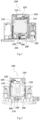
Fig. 1 shows a schematic front view of an alarm system according to an embodiment of the present invention; -
Fig. 2 shows a schematic rear view of an alarm system according to an embodiment of the present invention; -
Fig. 3 shows a schematic rear view of an alarm system according to an embodiment of the present invention, in which a solder joint is in the failure state; -
Fig. 4 shows a schematic top view of an alarm system according to an embodiment of the present invention. - Reference numerals: 100 alarm system, 110 varistor, 112 main body, 114 solder joint, 120 fuse bar, 130 pressing bar assembly, 132 first part, 134 second part, 140 first spring, 150 pressing plate, 152 through hole, 160 supporting piece, 162 boss, 170 second spring, 174 third spring, 180 microswitch, 182 button, 190 PCBA board.
- In order to make the purpose, solution and advantages of the technical solution of the present invention clearer, the technical solution of the embodiments of the present invention will be described clearly and completely with the attached drawings of a specific embodiment of the present invention. Unless otherwise specified, the terms used herein have the ordinary meaning in the art. In the drawings, the same reference numerals represent the same parts. The up, down, left and right directions in the drawings and the following description are only exemplary and are not intended to limit the orientation of any component in the system.
-
Fig. 1 shows a schematic front view of analarm system 100 for a surge protector according to an embodiment of the present invention. Thealarm system 100 mainly includes a plurality ofvaristors 110, a plurality offuse bars 120 corresponding to the plurality ofvaristors 110 and electrically connected with an external circuit, pressingbar assemblies 130 arranged around thevaristors 110,first springs 140, supportingpieces 160,second springs 170, apressing plate 150 and athird spring 174. The surge protector may include fourvaristors 110, of which three varistors are connected to the live wire and the other varistor is connected to the neutral wire. It should be understood that the number ofvaristors 110 in the surge protector described above is only exemplary, and the present invention does not intend to limit the number ofvaristors 110 included in the surge protector. For example, the surge protector may include two varistors, forming a 2P structure. Alternatively, the surge protector may include three varistors, forming a 3P or 3PN structure. - Each
varistor 110 has amain body 112 and asolder joint 114 protruding from themain body 112, and is configured to be connected to acorresponding fuse bar 120 via thesolder joint 114. Thefuse bar 120 abuts against apressing bar assembly 130 when thecorresponding solder joint 114 is not failed, so as to block the movement of thepressing bar assembly 130. Thefirst springs 140 extend in a first direction (e.g., the left-right direction as shown inFigure 1 ) and each abuts against a correspondingpressing bar assembly 130 to bias the correspondingpressing bar assembly 130 in the first direction. Thepressing plate 150 has a plurality of throughholes 152 each corresponding to a correspondingpressing bar assembly 130. The supportingpieces 160 each passes through a corresponding throughhole 152 and abuts against the correspondingpressing bar assembly 130 when thecorresponding solder joint 114 is not failed. Thesecond springs 170 extend in a second direction (e.g., up-down direction as shown inFigure 1 ) perpendicular to the first direction (e.g., left-right direction as shown inFigure 1 ) and is configured to each bias the correspondingsupporting piece 160 toward thecorresponding varistor 110. Themicroswitch 180 includes abutton 182 and is arranged on a side of thepressing plate 150 away from thepressing rod assemblies 130. Thepressing plate 150 presses or releases thebutton 182 to switch themicroswitch 180 between a first state and a second state. When thebutton 182 is pressed, themicroswitch 180 is in the first state, and when thebutton 182 is released, themicroswitch 180 is in the second state. Thethird spring 174 is configured to bias thepressing plate 150 toward themicroswitch 180. - According to the above arrangement, when the
respective solder joints 114 of all thevaristors 110 of the plurality of varistors are in the normal state, thefuse bars 120 are fixed to therespective solder joints 114 so as to block the left-right movement of thepressing bar assemblies 130, and another end of eachpressing bar assembly 130 further blocks the upward movement of respective supportingpiece 160 so that the supportingpieces 160 do not contact the pressing plate 150 (preferably, there is a gap between aboss 162 of each supportingpiece 160 and the pressing plate 150) and thepressing plate 150 cannot be pushed upward, so that thepressing plate 150 is kept in a position of pressing thebutton 182 of themicroswitch 180, so that themicroswitch 180 is kept in the first state. On the other hand, when thesolder joint 114 of any one of thevaristors 110 of the plurality of varistors fails, thecorresponding fuse bar 120 is detached from thepressing bar assembly 130 and no longer blocks the movement of thepressing bar assembly 130, so that thepressing bar assembly 130 moves in the first direction (e.g., the left-right direction as shown inFigure 1 ) under the action of the correspondingfirst spring 140, so that thepressing bar assembly 130 is out of abutment with the corresponding supportingpiece 160, so that the correspondingsecond spring 170 is released from the compressed state. Because the force of asecond spring 170 on thepressing plate 150 is greater than the force of thethird spring 174 on thepressing plate 150, the supportingpiece 160 drives thepressing plate 150 to move toward the pressing bar assemblies (i.e., move upward inFigure 1 ) to release thebutton 182 of themicroswitch 180, so that themicroswitch 180 switches from the first state to the second state. - In other words, as shown in
Figure 1 , when thesolder joint 114 of avaristor 110 does not fail, thefuse bar 120 constrains the freedom of the left-right movement of thepressing bar assembly 130, so that thepressing bar assembly 130 constrains the freedom of the upward movement of the supportingpiece 160. As shown inFigure 3 , when thesolder joint 114 of avaristor 110 fails, the constrained degree of freedom is released, so that the supportingpiece 160 drives thepressing plate 150 to move upward, thereby releasing thebutton 182 pressed by thepressing plate 150, and further switching the state of themicroswitch 180. It is worth noting that as long as thesolder joint 114 of any one of thevaristors 110 fails (without the need for thesolder joints 114 of the plurality ofvaristors 110 to fail), thepressing plate 150 can move upward under the drive of the corresponding released supportingpiece 160 to switch the state of themicroswitch 180. In this way, the monitoring of the solder joint states of the plurality ofvaristors 110 is achieved by only onemicroswitch 180, thereby greatly reducing the manufacturing cost of thealarm system 100. - It should be understood that, the
first spring 140 that drives thepressing bar assembly 130 to move in the first direction after thesolder joint 114 of thevaristor 110 fails is only exemplary, and any other suitable driving component may be used to drive thepressing bar assembly 130 to move in the first direction. Similarly, thesecond spring 170 that drives the supportingpiece 160 to move in the second direction after thesolder joint 114 of thevaristor 110 fails is only exemplary, and any other suitable driving component may be used to drive the supportingpiece 160 to move in the second direction. Furthermore, thethird spring 174 configured to bias the supportingpiece 160 toward themicroswitch 180 is only exemplary, and any other suitable biasing component may be used to bias the supportingpiece 160 toward themicroswitch 180. - Optionally, each supporting
piece 160 may have aboss 162 protruding perpendicular to the up-down direction, and theboss 162 is arranged on the side of thepressing plate 150 away from the pressing bar assemblies 130 (i.e., the lower side of thepressing plate 150 shown inFigure 1 ) and can abut against thepressing plate 150 under the action of thesecond spring 170 to drive thepressing plate 150 to move upward. - Optionally, as shown in
Figure 2 , thepressing bar assembly 130 may include afirst part 132 and asecond part 134. When thecorresponding solder joint 114 is effective, thefuse bar 120 abuts against thefirst part 132 of the correspondingpressing bar assembly 130, eachfirst spring 140 abuts against thefirst part 132 of the correspondingpressing bar assembly 130, and each supportingpiece 160 abuts against thesecond part 134 of the correspondingpressing bar assembly 130. Thefirst part 132 and thesecond part 134 form a T-shaped structure. Thefirst part 132 and thesecond part 134 may be connected together by any suitable means, such as riveting. Optionally, thesolder joint 114 of avaristor 110 may be arranged on a side of thevaristor 110 away from the supporting piece 160 (for example, the upper side shown inFigure 1 ). - Optionally, the
alarm system 110 may further include a torsion spring. When thesolder joint 114 of avaristor 110 fails, thefuse bar 120 may be detached from thefirst part 132 of thepressing bar assembly 130 under the action of the torsion spring, thereby allowing thepressing bar assembly 130 to move under the action of thefirst spring 140. Preferably, thealarm system 110 may further include a limiting part, which is arranged on a side of thepressing plate 150 away from the pressing bar assembly 130 (for example, the lower side shown inFigure 1 ) to limit excessive movement of thepressing plate 150 toward thebutton 182 of themicroswitch 180, so as to prevent thepressing plate 150 from excessively pressing thebutton 182 of themicroswitch 180 and thereby causing unnecessary damage to themicroswitch 180. - Preferably, the
alarm system 100 may further include aPCBA board 190 electrically connected with themicroswitch 180 and an indicator communicatively coupled with the PCBA board for indicating the state of themicroswitch 180. Optionally, the indicator may be a light, which does not emit light when themicroswitch 180 is in the first state and emits light when themicroswitch 180 is in the second state. It should be understood that the present invention is not intended to limit the specific type of indicator, and the indicator may be any other suitable device capable of transmitting signals to the staff, such as a speaker. - A number of exemplary embodiments of the present invention have been described in detail herein with reference to preferred embodiments. However, those skilled in the art can understand that various variations and modifications can be made to the above specific embodiments without departing from the inventive concept, and various technical features and structures proposed by the present invention can be combined without exceeding the scope of protection of the present invention, which is determined by the appended claims.
Claims (14)
- An alarm system characterized in that the alarm system is for a surge protector and comprises:a varistor module comprising a plurality of varistors, each varistor having a main body and a solder joint protruding from the main body;a plurality of fuse bars electrically connected with an external circuit, each varistor configured to be connected to a corresponding fuse bar via the solder joint;a plurality of pressing bar assemblies respectively arranged around a corresponding varistor, each fuse bar abutting against a corresponding pressing bar assembly when the corresponding solder joint is effective, so as to block the movement of the corresponding pressing bar assembly;a pressing plate with a plurality of through holes, each through hole corresponding to a corresponding pressing bar assembly, and the pressing plate is biased towards a microswitch under an action of a biasing component;a plurality of supporting pieces, each supporting piece passing through a corresponding through hole and abutting against a corresponding pressing bar assembly when the corresponding solder joint is effective;a microswitch comprising a button and arranged at a side of the pressing plate away from the pressing rod assemblies, wherein the pressing plate presses or releases the button to switch the microswitch between a first state and a second state, wherein the microswitch is in the first state when the button is pressed and in the second state when the button is released;wherein, when the solder joint of any one of the plurality of varistors fails, the corresponding fuse bar is detached from the pressing bar assembly, so that the pressing bar assembly moves in a first direction under an action of a corresponding first driving component, so that the pressing bar assembly is out of abutment with the corresponding supporting piece, so that the supporting piece drives the pressing plate to move towards the pressing bar assemblies under an action of a corresponding second driving component so as to release the button.
- The alarm system according to claim 1, characterized in that the first driving component is a first spring, wherein the first spring extends in the first direction, the first spring abuts against the corresponding pressing bar assembly and is configured to bias the corresponding pressing bar assembly in the first direction.
- The alarm system according to claim 2, characterized in that the second driving component is a second spring, wherein the second spring extends in a second direction perpendicular to the first direction, and the second spring is configured to bias the corresponding supporting piece toward the corresponding varistor.
- The alarm system according to claim 3, characterized in that the biasing component is a third spring.
- The alarm system according to claim 3, characterized in that each supporting piece has a boss protruding perpendicular to the second direction, and the boss is arranged on a side of the pressing plate away from the pressing bar assemblies, and when the solder joint fails, the boss abuts against the pressing plate under the action of the second spring.
- The alarm system according to claim 1, characterized in that the pressing bar assembly comprises a first part and a second part, when the corresponding solder joint is effective, the fuse bar abuts against the first part of the corresponding pressing bar assembly, each of the first springs abuts against the first part of the corresponding pressing bar assembly, and each of the supporting pieces abuts against the second part of the corresponding pressing bar assembly, and the first part and the second part form a T-shaped structure.
- The alarm system according to claim 1, characterized in that the solder joint is arranged on a side of the varistor away from the supporting piece.
- The alarm system according to claim 6, characterized in that the alarm system further comprises a torsion spring, and when the solder joint fails, the fuse bar is detached from the first part of the pressing bar assembly under an action of the torsion spring, thereby allowing the pressing bar assembly to move under the action of the first spring.
- The alarm system according to claim 1, characterized in that the alarm system further comprises a limiting component, wherein the limiting component is arranged at a side of the pressing plate away from the pressing bar assemblies to limit an excessive movement of the pressing plate towards the button.
- The alarm system according to claim 1, characterized in that the alarm system further comprises a PCBA board which is electrically connected with the microswitch.
- The alarm system according to claim 10, characterized in that the alarm system further comprises an indicator communicatively coupled with the PCBA board for indicating the state of the microswitch.
- The alarm system according to claim 11, characterized in that the indicator is a light, wherein the light does not emit light when the microswitch is in the first state and emits light when the microswitch is in the second state.
- A surge protector, characterized in that the surge protector comprises the alarm system according to any one of claims 1 to 12.
- The surge protector according to claim 13, characterized in that the surge protector comprises four varistors, of which three varistors are connected to the live wire and the other varistor is connected to the neutral wire.
Applications Claiming Priority (1)
| Application Number | Priority Date | Filing Date | Title |
|---|---|---|---|
| CN202311726039 | 2023-12-14 |
Publications (1)
| Publication Number | Publication Date |
|---|---|
| EP4571809A1 true EP4571809A1 (en) | 2025-06-18 |
Family
ID=93562736
Family Applications (1)
| Application Number | Title | Priority Date | Filing Date |
|---|---|---|---|
| EP24306855.8A Pending EP4571809A1 (en) | 2023-12-14 | 2024-11-04 | Surge protector with alarm system |
Country Status (2)
| Country | Link |
|---|---|
| EP (1) | EP4571809A1 (en) |
| CN (1) | CN120165348A (en) |
Citations (6)
| Publication number | Priority date | Publication date | Assignee | Title |
|---|---|---|---|---|
| CN101261893A (en) * | 2008-04-14 | 2008-09-10 | 佛山市浦斯电子有限公司 | Heat protection pressure sensitive resistor module |
| EP3422370A1 (en) * | 2017-06-26 | 2019-01-02 | Shanghai Hanghai Chenzhu Instrument Co., Ltd. | Surge protector, and release mechanism and base thereof |
| CN212137278U (en) * | 2020-05-11 | 2020-12-11 | 深圳普泰电气有限公司 | Surge protector |
| CN212784767U (en) * | 2020-08-31 | 2021-03-23 | 常州市创捷防雷电子有限公司 | Remote signaling device of large-current surge protector |
| US20210366677A1 (en) * | 2018-10-15 | 2021-11-25 | Dehn Se + Co Kg | Surge protection device having a plurality of surge arresters and, in particular thermal, isolating apparatus which is respectively associated with them |
| WO2022226958A1 (en) * | 2021-04-30 | 2022-11-03 | 上海辰竹防雷科技有限公司 | Surge protection module and surge protection device |
-
2024
- 2024-05-30 CN CN202410692427.6A patent/CN120165348A/en active Pending
- 2024-11-04 EP EP24306855.8A patent/EP4571809A1/en active Pending
Patent Citations (6)
| Publication number | Priority date | Publication date | Assignee | Title |
|---|---|---|---|---|
| CN101261893A (en) * | 2008-04-14 | 2008-09-10 | 佛山市浦斯电子有限公司 | Heat protection pressure sensitive resistor module |
| EP3422370A1 (en) * | 2017-06-26 | 2019-01-02 | Shanghai Hanghai Chenzhu Instrument Co., Ltd. | Surge protector, and release mechanism and base thereof |
| US20210366677A1 (en) * | 2018-10-15 | 2021-11-25 | Dehn Se + Co Kg | Surge protection device having a plurality of surge arresters and, in particular thermal, isolating apparatus which is respectively associated with them |
| CN212137278U (en) * | 2020-05-11 | 2020-12-11 | 深圳普泰电气有限公司 | Surge protector |
| CN212784767U (en) * | 2020-08-31 | 2021-03-23 | 常州市创捷防雷电子有限公司 | Remote signaling device of large-current surge protector |
| WO2022226958A1 (en) * | 2021-04-30 | 2022-11-03 | 上海辰竹防雷科技有限公司 | Surge protection module and surge protection device |
Also Published As
| Publication number | Publication date |
|---|---|
| CN120165348A (en) | 2025-06-17 |
Similar Documents
| Publication | Publication Date | Title |
|---|---|---|
| JP5789875B2 (en) | Thermal overload protection structure | |
| US7839257B2 (en) | Overvoltage protection with status signalling | |
| JP2016536783A (en) | Compact overvoltage protection device that can be assembled in advance | |
| JP2013212563A (en) | Switch box, teaching device, robot controller, and method for using robot controller | |
| JP6073457B2 (en) | Anomaly indicators for electronic devices, especially surge arresters | |
| CN112398083A (en) | A miniaturized overvoltage protector | |
| US11295914B2 (en) | Surge protection device having a plurality of surge arresters and, in particular thermal, isolating apparatus which is respectively associated with them | |
| RU2335054C2 (en) | Device for tapping overvoltage with one or several elements connected in parallel to limit overvoltage and arranged in common assembly unit | |
| KR102073931B1 (en) | Apparatus and method for handling the short of speaker lines and protecting the speaker lines, and the brosdcasting system comprising the same | |
| CN214672468U (en) | A signal SPD tripping mechanism | |
| CN120165348A (en) | An alarm system and a surge protector | |
| JP2022531760A (en) | Surge protection devices and modular surge protection systems | |
| NL193741C (en) | Device for monitoring the operation of surge arresters. | |
| CN214411006U (en) | Dual-power transfer switch with selectable overload alarm non-tripping function | |
| CN214755506U (en) | A trip alarm module, an alarm lightning protection device and an alarm lightning protection device | |
| CN214674336U (en) | Linkage mechanism, base and surge protection device | |
| CN210606049U (en) | Reliable anti-error signal contact device | |
| CN119601424B (en) | Self-recoverable three-terminal fuse | |
| CN219936890U (en) | Status indicating device and surge protector comprising same | |
| CN113113273A (en) | Signal SPD tripping mechanism | |
| CN113131454A (en) | Linkage mechanism, base and surge protection device | |
| CN1947317A (en) | Overvoltage bypass device comprising one or more overvoltage limiting elements arranged in parallel in a structural unit | |
| CN220420514U (en) | Accessory integrated components and circuit breakers | |
| CN110911226B (en) | Electrical component assembly with carrier | |
| CN119208079B (en) | Self-recoverable three-terminal fuse |
Legal Events
| Date | Code | Title | Description |
|---|---|---|---|
| PUAI | Public reference made under article 153(3) epc to a published international application that has entered the european phase |
Free format text: ORIGINAL CODE: 0009012 |
|
| STAA | Information on the status of an ep patent application or granted ep patent |
Free format text: STATUS: THE APPLICATION HAS BEEN PUBLISHED |
|
| AK | Designated contracting states |
Kind code of ref document: A1 Designated state(s): AL AT BE BG CH CY CZ DE DK EE ES FI FR GB GR HR HU IE IS IT LI LT LU LV MC ME MK MT NL NO PL PT RO RS SE SI SK SM TR |
|
| STAA | Information on the status of an ep patent application or granted ep patent |
Free format text: STATUS: REQUEST FOR EXAMINATION WAS MADE |
|
| 17P | Request for examination filed |
Effective date: 20251201 |