EP4571741A1 - Method for separating target sound source from mixed sound source and electronic device thereof - Google Patents
Method for separating target sound source from mixed sound source and electronic device thereof Download PDFInfo
- Publication number
- EP4571741A1 EP4571741A1 EP23855072.7A EP23855072A EP4571741A1 EP 4571741 A1 EP4571741 A1 EP 4571741A1 EP 23855072 A EP23855072 A EP 23855072A EP 4571741 A1 EP4571741 A1 EP 4571741A1
- Authority
- EP
- European Patent Office
- Prior art keywords
- sound source
- vector
- scene information
- embedding vector
- embedding
- Prior art date
- Legal status (The legal status is an assumption and is not a legal conclusion. Google has not performed a legal analysis and makes no representation as to the accuracy of the status listed.)
- Pending
Links
Images





Classifications
-
- G—PHYSICS
- G10—MUSICAL INSTRUMENTS; ACOUSTICS
- G10L—SPEECH ANALYSIS TECHNIQUES OR SPEECH SYNTHESIS; SPEECH RECOGNITION; SPEECH OR VOICE PROCESSING TECHNIQUES; SPEECH OR AUDIO CODING OR DECODING
- G10L21/00—Speech or voice signal processing techniques to produce another audible or non-audible signal, e.g. visual or tactile, in order to modify its quality or its intelligibility
- G10L21/02—Speech enhancement, e.g. noise reduction or echo cancellation
- G10L21/0272—Voice signal separating
- G10L21/0308—Voice signal separating characterised by the type of parameter measurement, e.g. correlation techniques, zero crossing techniques or predictive techniques
-
- G—PHYSICS
- G10—MUSICAL INSTRUMENTS; ACOUSTICS
- G10L—SPEECH ANALYSIS TECHNIQUES OR SPEECH SYNTHESIS; SPEECH RECOGNITION; SPEECH OR VOICE PROCESSING TECHNIQUES; SPEECH OR AUDIO CODING OR DECODING
- G10L25/00—Speech or voice analysis techniques not restricted to a single one of groups G10L15/00 - G10L21/00
- G10L25/78—Detection of presence or absence of voice signals
- G10L25/81—Detection of presence or absence of voice signals for discriminating voice from music
-
- G—PHYSICS
- G06—COMPUTING OR CALCULATING; COUNTING
- G06N—COMPUTING ARRANGEMENTS BASED ON SPECIFIC COMPUTATIONAL MODELS
- G06N20/00—Machine learning
-
- G—PHYSICS
- G06—COMPUTING OR CALCULATING; COUNTING
- G06N—COMPUTING ARRANGEMENTS BASED ON SPECIFIC COMPUTATIONAL MODELS
- G06N3/00—Computing arrangements based on biological models
- G06N3/02—Neural networks
- G06N3/04—Architecture, e.g. interconnection topology
- G06N3/045—Combinations of networks
-
- G—PHYSICS
- G06—COMPUTING OR CALCULATING; COUNTING
- G06N—COMPUTING ARRANGEMENTS BASED ON SPECIFIC COMPUTATIONAL MODELS
- G06N3/00—Computing arrangements based on biological models
- G06N3/02—Neural networks
- G06N3/08—Learning methods
-
- G—PHYSICS
- G06—COMPUTING OR CALCULATING; COUNTING
- G06V—IMAGE OR VIDEO RECOGNITION OR UNDERSTANDING
- G06V10/00—Arrangements for image or video recognition or understanding
- G06V10/70—Arrangements for image or video recognition or understanding using pattern recognition or machine learning
- G06V10/82—Arrangements for image or video recognition or understanding using pattern recognition or machine learning using neural networks
-
- G—PHYSICS
- G10—MUSICAL INSTRUMENTS; ACOUSTICS
- G10L—SPEECH ANALYSIS TECHNIQUES OR SPEECH SYNTHESIS; SPEECH RECOGNITION; SPEECH OR VOICE PROCESSING TECHNIQUES; SPEECH OR AUDIO CODING OR DECODING
- G10L25/00—Speech or voice analysis techniques not restricted to a single one of groups G10L15/00 - G10L21/00
- G10L25/27—Speech or voice analysis techniques not restricted to a single one of groups G10L15/00 - G10L21/00 characterised by the analysis technique
- G10L25/30—Speech or voice analysis techniques not restricted to a single one of groups G10L15/00 - G10L21/00 characterised by the analysis technique using neural networks
-
- G—PHYSICS
- G10—MUSICAL INSTRUMENTS; ACOUSTICS
- G10L—SPEECH ANALYSIS TECHNIQUES OR SPEECH SYNTHESIS; SPEECH RECOGNITION; SPEECH OR VOICE PROCESSING TECHNIQUES; SPEECH OR AUDIO CODING OR DECODING
- G10L25/00—Speech or voice analysis techniques not restricted to a single one of groups G10L15/00 - G10L21/00
- G10L25/48—Speech or voice analysis techniques not restricted to a single one of groups G10L15/00 - G10L21/00 specially adapted for particular use
- G10L25/51—Speech or voice analysis techniques not restricted to a single one of groups G10L15/00 - G10L21/00 specially adapted for particular use for comparison or discrimination
Definitions
- the disclosure relates to a method for separating a target sound source from a mixed sound source using scene information about a mixed sound source and an electronic device thereof.
- a microphone may be used to obtain sound in various digital devices, such as consumer electronics (CE) devices and mobile phones.
- CE consumer electronics
- the sound obtained by the microphone may include a plurality of sound sources that include background noise or other sounds not pertinent to a phone or video call.
- Sound source separation technology may be used to separate two or more sounds for each sound source.
- sound source separation technology may be used to extract only the singer's voice from stereo music or separate two or more audio signals recorded with one microphone. Sound source separation technology may also be used for noise canceling in vehicles or mobile phones.
- Sound source separation technology may perform recording using several microphones, and then separate sound sources using the correlation between the signals obtained by the microphones. Meanwhile, methods for adopting artificial intelligence in sound source separation technology are being introduced. Some of these methods perform voice separation using pre-trained voices or noise patterns, or statistical data information.
- a method for separating a target sound source may comprise obtaining a mixed sound source including at least one sound source, obtaining, based on the mixed sound source, scene information related to the mixed sound source, converting, based on the scene information, a first embedding vector corresponding to a designated sound source group into a second embedding vector, and separating, based on the mixed sound source and the second embedding vector, the target sound source from the mixed sound source.
- an electronic device may comprise an input interface, a memory storing at least one instruction, and at least one processor operatively connected with the input interface and the memory.
- the at least one processor may be configured to execute the at least one instruction to, obtain a mixed sound source including at least one sound source from the input interface, obtain, based on the mixed sound source, scene information related to the mixed sound source, convert, based on the scene information, a first embedding vector corresponding to a designated sound source group into a second embedding vector, and separate, based on the mixed sound source and the second embedding vector, a target sound source from the mixed sound source.
- a non-transitory computer-readable storage medium storing one or more programs may comprise, based on execution of an application, obtaining a mixed sound source including at least one sound source, obtaining, based on the mixed sound source, scene information related to the mixed sound source, converting, based on the scene information, a first embedding vector corresponding to a designated sound source group into a second embedding vector, and separating, based on the obtained mixed sound source and the second embedding vector, the target sound source from the mixed sound source.
- FIG. 1 is a block diagram illustrating an electronic device 101 in a network environment 100 according to an embodiment of the disclosure.
- the electronic device 101 in the network environment 100 may communicate with at least one of an electronic device 102 via a first network 198 (e.g., a short-range wireless communication network), or an electronic device 104 or a server 108 via a second network 199 (e.g., a long-range wireless communication network).
- a first network 198 e.g., a short-range wireless communication network
- an electronic device 104 or a server 108 via a second network 199 (e.g., a long-range wireless communication network).
- the electronic device 101 may communicate with the electronic device 104 via the server 108.
- the electronic device 101 may include a processor 120, memory 130, an input module 150, a sound output module 155, a display module 160, an audio module 170, a sensor module 176, an interface 177, a connecting terminal 178, a haptic module 179, a camera module 180, a power management module 188, a battery 189, a communication module 190, a subscriber identification module (SIM) 196, or an antenna module 197.
- at least one (e.g., the connecting terminal 178) of the components may be omitted from the electronic device 101, or one or more other components may be added in the electronic device 101.
- some (e.g., the sensor module 176, the camera module 180, or the antenna module 197) of the components may be integrated into a single component (e.g., the display module 160).
- the processor 120 may execute, for example, software (e.g., a program 140) to control at least one other component (e.g., a hardware or software component) of the electronic device 101 coupled with the processor 120, and may perform various data processing or computation.
- the processor 120 may store a command or data received from another component (e.g., the sensor module 176 or the communication module 190) in volatile memory 132, process the command or the data stored in the volatile memory 132, and store resulting data in non-volatile memory 134.
- the processor 120 may include a main processor 121 (e.g., a central processing unit (CPU) or an application processor (AP)), or an auxiliary processor 123 (e.g., a graphics processing unit (GPU), a neural processing unit (NPU), an image signal processor (ISP), a sensor hub processor, or a communication processor (CP)) that is operable independently from, or in conjunction with, the main processor 121.
- a main processor 121 e.g., a central processing unit (CPU) or an application processor (AP)
- auxiliary processor 123 e.g., a graphics processing unit (GPU), a neural processing unit (NPU), an image signal processor (ISP), a sensor hub processor, or a communication processor (CP)
- the main processor 121 may be configured to use lower power than the main processor 121 or to be specified for a designated function.
- the auxiliary processor 123 may be implemented as separate from, or as part of the main processor 121.
- the auxiliary processor 123 may control at least some of functions or states related to at least one component (e.g., the display module 160, the sensor module 176, or the communication module 190) among the components of the electronic device 101, instead of the main processor 121 while the main processor 121 is in an inactive (e.g., sleep) state, or together with the main processor 121 while the main processor 121 is in an active state (e.g., executing an application).
- the auxiliary processor 123 e.g., an image signal processor or a communication processor
- the auxiliary processor 123 may include a hardware structure specified for artificial intelligence model processing.
- the artificial intelligence model may be generated via machine learning. Such learning may be performed, e.g., by the electronic device 101 where the artificial intelligence is performed or via a separate server (e.g., the server 108). Learning algorithms may include, but are not limited to, e.g., supervised learning, unsupervised learning, semi-supervised learning, or reinforcement learning.
- the artificial intelligence model may include a plurality of artificial neural network layers.
- the artificial neural network may be a deep neural network (DNN), a convolutional neural network (CNN), a recurrent neural network (RNN), a restricted Boltzmann machine (RBM), a deep belief network (DBN), a bidirectional recurrent deep neural network (BRDNN), deep Q-network or a combination of two or more thereof but is not limited thereto.
- the artificial intelligence model may, additionally or alternatively, include a software structure other than the hardware structure.
- the memory 130 may store various data used by at least one component (e.g., the processor 120 or the sensor module 176) of the electronic device 101.
- the various data may include, for example, software (e.g., the program 140) and input data or output data for a command related thereto.
- the memory 130 may include the volatile memory 132 or the non-volatile memory 134.
- the program 140 may be stored in the memory 130 as software, and may include, for example, an operating system (OS) 142, middleware 144, or an application 146.
- OS operating system
- middleware middleware
- application application
- the input module 150 may receive a command or data to be used by other component (e.g., the processor 120) of the electronic device 101, from the outside (e.g., a user) of the electronic device 101.
- the input module 150 may include, for example, a microphone, a mouse, a keyboard, keys (e.g., buttons), or a digital pen (e.g., a stylus pen).
- the sound output module 155 may output sound signals to the outside of the electronic device 101.
- the sound output module 155 may include, for example, a speaker or a receiver.
- the speaker may be used for general purposes, such as playing multimedia or playing record.
- the receiver may be used for receiving incoming calls. According to an embodiment, the receiver may be implemented as separate from, or as part of the speaker.
- the audio module 170 may convert a sound into an electrical signal and vice versa. According to an embodiment, the audio module 170 may obtain the sound via the input module 150, or output the sound via the sound output module 155 or a headphone of an external electronic device (e.g., an electronic device 102) directly (e.g., wiredly) or wirelessly coupled with the electronic device 101.
- an external electronic device e.g., an electronic device 102
- directly e.g., wiredly
- wirelessly e.g., wirelessly
- the sensor module 176 may detect an operational state (e.g., power or temperature) of the electronic device 101 or an environmental state (e.g., a state of a user) external to the electronic device 101, and then generate an electrical signal or data value corresponding to the detected state.
- the sensor module 176 may include, for example, a gesture sensor, a gyro sensor, an atmospheric pressure sensor, a magnetic sensor, an accelerometer, a grip sensor, a proximity sensor, a color sensor, an infrared (IR) sensor, a biometric sensor, a temperature sensor, a humidity sensor, or an illuminance sensor.
- the interface 177 may support one or more specified protocols to be used for the electronic device 101 to be coupled with the external electronic device (e.g., the electronic device 102) directly (e.g., wiredly) or wirelessly.
- the interface 177 may include, for example, a high definition multimedia interface (HDMI), a universal serial bus (USB) interface, a secure digital (SD) card interface, or an audio interface.
- HDMI high definition multimedia interface
- USB universal serial bus
- SD secure digital
- a connecting terminal 178 may include a connector via which the electronic device 101 may be physically connected with the external electronic device (e.g., the electronic device 102).
- the connecting terminal 178 may include, for example, a HDMI connector, a USB connector, a SD card connector, or an audio connector (e.g., a headphone connector).
- the haptic module 179 may convert an electrical signal into a mechanical stimulus (e.g., a vibration or motion) or electrical stimulus which may be recognized by a user via his tactile sensation or kinesthetic sensation.
- the haptic module 179 may include, for example, a motor, a piezoelectric element, or an electric stimulator.
- the camera module 180 may capture a still image or moving images.
- the camera module 180 may include one or more lenses, image sensors, image signal processors, or flashes.
- the power management module 188 may manage power supplied to the electronic device 101.
- the power management module 188 may be implemented as at least part of, for example, a power management integrated circuit (PMIC).
- PMIC power management integrated circuit
- the battery 189 may supply power to at least one component of the electronic device 101.
- the battery 189 may include, for example, a primary cell which is not rechargeable, a secondary cell which is rechargeable, or a fuel cell.
- the communication module 190 may support establishing a direct (e.g., wired) communication channel or a wireless communication channel between the electronic device 101 and the external electronic device (e.g., the electronic device 102, the electronic device 104, or the server 108) and performing communication via the established communication channel.
- the communication module 190 may include one or more communication processors that are operable independently from the processor 120 (e.g., the application processor (AP)) and supports a direct (e.g., wired) communication or a wireless communication.
- AP application processor
- the communication module 190 may include a wireless communication module 192 (e.g., a cellular communication module, a short-range wireless communication module, or a global navigation satellite system (GNSS) communication module) or a wired communication module 194 (e.g., a local area network (LAN) communication module or a power line communication (PLC) module).
- a wireless communication module 192 e.g., a cellular communication module, a short-range wireless communication module, or a global navigation satellite system (GNSS) communication module
- GNSS global navigation satellite system
- wired communication module 194 e.g., a local area network (LAN) communication module or a power line communication (PLC) module.
- LAN local area network
- PLC power line communication
- a corresponding one of these communication modules may communicate with the external electronic device 104 via a first network 198 (e.g., a short-range communication network, such as Bluetooth TM , wireless-fidelity (Wi-Fi) direct, or infrared data association (IrDA)) or a second network 199 (e.g., a long-range communication network, such as a legacy cellular network, a 5G network, a next-generation communication network, the Internet, or a computer network (e.g., local area network (LAN) or wide area network (WAN)).
- a first network 198 e.g., a short-range communication network, such as Bluetooth TM , wireless-fidelity (Wi-Fi) direct, or infrared data association (IrDA)
- a second network 199 e.g., a long-range communication network, such as a legacy cellular network, a 5G network, a next-generation communication network, the Internet, or a computer network (e.g., local area
- the wireless communication module 192 may identify or authenticate the electronic device 101 in a communication network, such as the first network 198 or the second network 199, using subscriber information (e.g., international mobile subscriber identity (IMSI)) stored in the subscriber identification module 196.
- subscriber information e.g., international mobile subscriber identity (IMSI)
- the wireless communication module 192 may support a 5G network, after a 4G network, and next-generation communication technology, e.g., new radio (NR) access technology.
- the NR access technology may support enhanced mobile broadband (eMBB), massive machine type communications (mMTC), or ultra-reliable and low-latency communications (URLLC).
- eMBB enhanced mobile broadband
- mMTC massive machine type communications
- URLLC ultra-reliable and low-latency communications
- the wireless communication module 192 may support a high-frequency band (e.g., the mmWave band) to achieve, e.g., a high data transmission rate.
- the wireless communication module 192 may support various technologies for securing performance on a high-frequency band, such as, e.g., beamforming, massive multiple-input and multiple-output (massive MIMO), full dimensional MIMO (FD-MIMO), array antenna, analog beamforming, or large scale antenna.
- the wireless communication module 192 may support various requirements specified in the electronic device 101, an external electronic device (e.g., the electronic device 104), or a network system (e.g., the second network 199).
- the wireless communication module 192 may support a peak data rate (e.g., 20Gbps or more) for implementing eMBB, loss coverage (e.g., 164dB or less) for implementing mMTC, or U-plane latency (e.g., 0.5ms or less for each of downlink (DL) and uplink (UL), or a round trip of 1ms or less) for implementing URLLC.
- a peak data rate e.g., 20Gbps or more
- loss coverage e.g., 164dB or less
- U-plane latency e.g., 0.5ms or less for each of downlink (DL) and uplink (UL), or a round trip of 1ms or less
- the antenna module 197 may transmit or receive a signal or power to or from the outside (e.g., the external electronic device).
- the antenna module 197 may include one antenna including a radiator formed of a conductive body or conductive pattern formed on a substrate (e.g., a printed circuit board (PCB)).
- the antenna module 197 may include a plurality of antennas (e.g., an antenna array). In this case, at least one antenna appropriate for a communication scheme used in a communication network, such as the first network 198 or the second network 199, may be selected from the plurality of antennas by, e.g., the communication module 190.
- the signal or the power may then be transmitted or received between the communication module 190 and the external electronic device via the selected at least one antenna.
- other parts e.g., radio frequency integrated circuit (RFIC)
- RFIC radio frequency integrated circuit
- the antenna module 197 may form a mmWave antenna module.
- the mmWave antenna module may include a printed circuit board, a RFIC disposed on a first surface (e.g., the bottom surface) of the printed circuit board, or adjacent to the first surface and capable of supporting a designated high-frequency band (e.g., the mmWave band), and a plurality of antennas (e.g., array antennas) disposed on a second surface (e.g., the top or a side surface) of the printed circuit board, or adjacent to the second surface and capable of transmitting or receiving signals of the designated high-frequency band.
- a RFIC disposed on a first surface (e.g., the bottom surface) of the printed circuit board, or adjacent to the first surface and capable of supporting a designated high-frequency band (e.g., the mmWave band)
- a plurality of antennas e.g., array antennas
- At least some of the above-described components may be coupled mutually and communicate signals (e.g., commands or data) therebetween via an inter-peripheral communication scheme (e.g., a bus, general purpose input and output (GPIO), serial peripheral interface (SPI), or mobile industry processor interface (MIPI)).
- an inter-peripheral communication scheme e.g., a bus, general purpose input and output (GPIO), serial peripheral interface (SPI), or mobile industry processor interface (MIPI)
- the one or more external electronic devices receiving the request may perform the at least part of the function or the service requested, or an additional function or an additional service related to the request, and transfer an outcome of the performing to the electronic device 101.
- the electronic device 101 may provide the outcome, with or without further processing of the outcome, as at least part of a reply to the request.
- a cloud computing, distributed computing, mobile edge computing (MEC), or client-server computing technology may be used, for example.
- the electronic device 101 may provide ultra low-latency services using, e.g., distributed computing or mobile edge computing.
- the external electronic device 104 may include an Internet-of-things (IoT) device.
- the server 108 may be an intelligent server using machine learning and/or a neural network.
- the external electronic device 104 or the server 108 may be included in the second network 199.
- the electronic device 101 may be applied to intelligent services (e.g., smart home, smart city, smart car, or health-care) based on 5G communication technology or IoT-related technology.
- the electronic device may be one of various types of electronic devices.
- the electronic devices may include, for example, a portable communication device (e.g., a smart phone), a computer device, a portable multimedia device, a portable medical device, a camera, an electronic device, or a home appliance.
- a portable communication device e.g., a smart phone
- a computer device e.g., a personal computer
- a portable multimedia device e.g., a portable medical device
- a camera e.g., a camera
- an electronic device e.g., a smart phone
- the electronic devices are not limited to those described above.
- each of such phrases as “A or B,” “at least one of A and B,” “at least one of A or B,” “A, B, or C,” “at least one of A, B, and C,” and “at least one of A, B, or C,” may include all possible combinations of the items enumerated together in a corresponding one of the phrases.
- such terms as “1st” and “2nd,” or “first” and “second” may be used to simply distinguish a corresponding component from another, and does not limit the components in other aspect (e.g., importance or order).
- an element e.g., a first element
- the element may be coupled with the other element directly (e.g., wiredly), wirelessly, or via a third element.
- module may include a unit implemented in hardware, software, or firmware, and may interchangeably be used with other terms, for example, “logic,” “logic block,” “part,” or “circuitry”.
- a module may be a single integral component, or a minimum unit or part thereof, adapted to perform one or more functions.
- the module may be implemented in a form of an application-specific integrated circuit (ASIC).
- ASIC application-specific integrated circuit
- An embodiment of the disclosure may be implemented as software (e.g., the program 140) including one or more instructions that are stored in a storage medium (e.g., internal memory 136 or external memory 138) that is readable by a machine (e.g., the electronic device 101).
- a processor e.g., the processor 120
- the machine e.g., the electronic device 101
- the one or more instructions may include a code generated by a complier or a code executable by an interpreter.
- the machine-readable storage medium may be provided in the form of a non-transitory storage medium.
- non-transitory simply means that the storage medium is a tangible device, and does not include a signal (e.g., an electromagnetic wave), but this term does not differentiate between where data is semi-permanently stored in the storage medium and where the data is temporarily stored in the storage medium.
- a method may be included and provided in a computer program product.
- the computer program products may be traded as commodities between sellers and buyers.
- the computer program product may be distributed in the form of a machine-readable storage medium (e.g., compact disc read only memory (CD-ROM)), or be distributed (e.g., downloaded or uploaded) online via an application store (e.g., Play Store TM ), or between two user devices (e.g., smart phones) directly. If distributed online, at least part of the computer program product may be temporarily generated or at least temporarily stored in the machine-readable storage medium, such as memory of the manufacturer's server, a server of the application store, or a relay server.
- CD-ROM compact disc read only memory
- an application store e.g., Play Store TM
- two user devices e.g., smart phones
- each component e.g., a module or a program of the above-described components may include a single entity or multiple entities. Some of the plurality of entities may be separately disposed in different components. According to various embodiments, one or more of the above-described components may be omitted, or one or more other components may be added. Alternatively or additionally, a plurality of components (e.g., modules or programs) may be integrated into a single component. In such a case, according to various embodiments, the integrated component may still perform one or more functions of each of the plurality of components in the same or similar manner as they are performed by a corresponding one of the plurality of components before the integration.
- the integrated component may still perform one or more functions of each of the plurality of components in the same or similar manner as they are performed by a corresponding one of the plurality of components before the integration.
- operations performed by the module, the program, or another component may be carried out sequentially, in parallel, repeatedly, or heuristically, or one or more of the operations may be executed in a different order or omitted, or one or more other operations may be added.
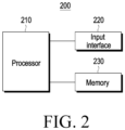
- FIG. 2 is a block diagram illustrating an electronic device 200 according to an embodiment of the disclosure.
- an electronic device 200 may include an input interface 220, a memory 230, and/or a processor 210.
- the input interface 220 may be a portion of an input module (e.g., the input module 150 of FIG. 1 ) that receives sound data from a source external to the electronic device (e.g., the user) and may be, for example, a microphone.
- the memory 230 may store various commands or data used by at least one component (e.g., the processor 120 or the sensor module 176 of FIG. 1 ) of the electronic device 200.
- the memory 230 may include a non-volatile memory, a volatile memory, a flash memory, a hard disk drive (HDD) or a solid state drive (SDD).
- the memory 230 may be accessed by the processor 210, and data read/record/modify/delete/update may be carried out by the processor 210.
- the processor 210 may execute the commands or operations stored in the memory 230. Specific commands or operations of the processor 210 are described below.
- the processor 210 may train a neural network using a program stored in the memory 230.
- the processor 210 may train the neural network for generating a pre-defined scene information vector based on obtaining an input sound source, generating a partial embedding vector corresponding to each target sound source included in a designated sound source group, or generating an embedding vector based on an embedding vector between specific scene information and a specific target sound source.
- the neural network may be designed to emulate the high learning capacity of the human brain on the computer and may include a plurality of weighted network nodes which emulate the neurons of the human neural network.
- the plurality of network nodes may send and receive data according to their respective connection relationships so as to simulate the synaptic activity of neurons that send and receive signals through synapses.
- the neural network may include a deep learning model developed from the neural network model.
- a deep learning model a plurality of network nodes may be located in different layers and exchange data according to a convolutional connection relationship.
- Examples of neural network models include a deep neural network (DNN), a convolutional neural network (CNN), a recurrent neural network, a restricted Boltzmann machine, a deep belief network, a deep Q-Network, or such various deep learning schemes and may be applied in fields such as vision recognition, speech recognition, natural language processing, and voice/signal processing.
- the processor 210 may be a general-purpose processor (e.g., CPU), may be an AI-dedicated processor (e.g., GPU) for artificial intelligence learning, or may be any other processor structure known to one of ordinary skill in the art.
- a general-purpose processor e.g., CPU
- an AI-dedicated processor e.g., GPU
- the processor 210 may be any other processor structure known to one of ordinary skill in the art.
- the memory 230 may store the neural network model generated through the learning algorithm for classifying or recognizing data.
- the memory 230 may store a deep learning model generated as a result of learning performed by the processor 210.
- the processor may include a data learning unit for learning the neural network for data classification or recognition.
- the data learning unit may learn criteria as to how to classify and recognize data using learning data as well as what learning data to use to determine data classification/recognition.
- the data learning unit may obtain learning data to be used for training and apply the obtained learning data to the deep learning model to train the deep learning model.
- the data learning unit may be manufactured in the form of at least one hardware chip (e.g., integrated circuit (IC)) which are to be equipped as part of the processor 210.
- the data learning unit may be implemented as software.
- the software module When implemented as a software module (or program module including instructions), the software module may be stored in non-transitory computer-readable media.
- the at least one software module may be provided by the operating system (OS) or by an application.
- the data learning unit may include a learning data obtaining unit and a model learning unit.
- the learning data obtaining unit may obtain learning data necessary for the neural network model for classifying and recognizing data.
- the model learning unit may train the neural network model to have determination criteria regarding how to classify predetermined data using the obtained learning data.
- the model learning unit may train the neural network model via supervised learning which uses at least part of the learning data as a reference for determination.
- the model learning unit may train the neural network model through unsupervised learning that discovers determination criteria by being self-trained using learning data without supervision.
- the model learning unit may train the neural network model through reinforcement learning using feedback about whether the result of determination of context according to learning is correct.
- the model learning unit may train the neural network model using learning algorithms including, for example, error back-propagation or gradient descent.
- the model learning unit may store the trained neural network model in the memory 230.
- the model learning unit may store the trained neural network model in a memory of a server connected to the electronic device through a wired or wireless network.
- the data learning unit may pre-process the obtained data to enhance the analysis result of the recognition model, save resources or time necessary to generate the recognition model, or allow the obtained data to be used for learning for context determination.
- the data learning unit may process the obtained data into a designated format to allow the model learning unit to use the obtained learning data for learning for image recognition.
- the data learning unit may select data necessary for learning from among the obtained learning data or the pre-processed learning data. The selected learning data may be provided to the model learning unit.
- the data learning unit may further include a model evaluating unit to enhance the analysis result of the neural network model.
- the model evaluating unit may enter evaluation data to the neural network model and, when the analysis result output from the evaluation data fails to meet a predetermined reference, allow the model learning unit to re-learn.
- the evaluation data may be data defined to evaluate the recognition model.
- the model evaluating unit may evaluate that the recognition model fails to meet a predetermined reference.
- processor 210 and the memory 230 are described as functionally divided from each other, the above-described components may be integrated into a single module which may be referred to as an AI module.
- the above-described artificial intelligence technology may be used in voice processing fields, such as sound source separation, voice extraction, or noise cancellation.
- voice processing fields such as sound source separation, voice extraction, or noise cancellation.
- audio signal analysis technology and deep learning technology may be combined to separate components for each sound source and use the same to extract only a desired target sound source from a plurality of sound sources or create new content based on the separated sound source.
- FIGS. 3A and 3B are flowcharts illustrating methods 300a and 300b for separating a target sound source according to an embodiment of the disclosure.
- FIG. 4 is a view schematically illustrating a system 400 for separating a target sound source according to an embodiment of the disclosure.
- a system 400 for separating a target sound source from a plurality of sound sources may include a scene extractor 410 receiving a mixed sound source and outputting scene information, an embedding layer 420 learning an embedding vector corresponding to at least one target sound source included in a designated sound source group, a refining network 430 refining the learned embedding vector of the embedding layer 420 based on the scene information, and a separation layer 440 separating the mixed sound source based on the refined embedding vector.
- N may be the number of sounds (e.g., acoustic events) included in the designated sound group.
- the target sound vector o may be a one-hot vector, where the element (o_n) corresponding to the target sound may be set to 1, and another element (o_j) (where j is not n) may be set to 0.
- DNN deep neural network
- a Conv-TasNet architecture configured to separate sound sources in the time domain and extract frameworks may be used.
- h_f denotes the feature of the fth frame of the D dimension, which is the dimension of the feature space, and F is the total number of frames.
- the system 400 for separating the target sound source may refine the preset embedding vector [ e 1 , ⁇ , e N ] through the scene information about the input mixed sound source.
- the methods 300a and 300b for separating the target sound source may include one or more operations 300a for pre-training the system 400 for separating the target sound source and one or more operations 300b for separating the target sound source using the trained system.
- the sound source obtained in operation 310 may be a sound source for pre-training and may be the same or different from the mixed sound source described below, and may include at least one sound source.
- the electronic device may perform each of a first pre-training process, a second pre-training process, a third pre-training process, and a fourth pre-training process. Specific pre-training by the electronic device is described below.
- the electronic device may separate the target sound source from the mixed sound source after training is complete by the pre-training.
- a first pre-training process may be performed to learn a scene information vector.
- a second pre-training process may be performed to learn partial embedding vectors each corresponding to a respective sound included in a preset sound group. For example, if the preset sound group includes 3 preset sounds, 3 partial embedding vectors are learned.
- a third pre-training process may be performed to learn, based on an embedding vector between specific scene information and a specific sound source corresponding to specific scene information, a conversion from a first embedding vector to a second embedding vector.
- a fourth pre-training process may be performed to learn to separate a target sound source from a plurality of sounds based on the input sound source and a second embedding vector.
- the electronic device may obtain a mixed sound source including at least one sound source.
- the mixed sound source may be generated by being received from an external environment through an input interface (e.g., the communication module 190 of FIG. 1 ) and be generated through the microphone (e.g., the input interface 220 of FIG. 2 ) included in the electronic device.
- the electronic device may receive the mixed sound source, generated through a microphone of an external device, through the input interface.
- the mixed sound source may be artificially generated, or after generated, filtered or processed.
- the mixed sound source may include the target sound source to be separated or may include other sound sources.
- y is the input signal corresponding to the mixed sound source
- s target,n is the signal corresponding to the nth target sound source to be separated
- s other is the signal corresponding to a sound source other than the target sound source to be separated.
- the number of target sound sources is limited to two as an example, more target sound sources or other types of target sound sources may be present.
- the target sound source may include at least one sound source and be represented as the following equation.
- the electronic device may obtain scene information related to the mixed sound source based on the obtained mixed sound source.
- the scene extractor 410 of FIG. 4 may receive the mixed sound source, select appropriate scene information from a designated scene information group, and output the selected scene information.
- the scene extractor 410 may extract scene information corresponding to the mixed sound source from the received mixed sound source including at least one input sound source through an artificial neural network trained through the first pre-training.
- at least one respective corresponding sound source may be preset.
- the electronic device may convert a first embedding vector corresponding to the designated sound source group into a second embedding vector based on the obtained scene information.
- the embedding layer 420 of FIG. 4 may learn the first embedding vector corresponding to an entirety of the designated sound source group in the artificial neural network trained through the second pre-training.
- the refining network 430 of FIG. 4 may convert, through the artificial neural network trained through the third pre-training, the first embedding vector into the second embedding vector based on the obtained scene information.
- the embedding layer 420 of FIG. 4 may learn and store the first embedding vector, which is an embedding vector corresponding to the entirety of the designated sound source group.
- the designated sound source group may include at least one target sound source.
- the first embedding vector may be a sum vector of partial embedding vectors each corresponding to a respective target sound source.
- at least one target sound source that may be generated in each piece of scene information included in the scene information group may be preconfigured to correspond to a respective piece of scene information.
- the refining network 430 of FIG. 4 may convert the first embedding vector into a second embedding vector corresponding to scene information using a pre-trained neural network.
- the second embedding vector may be an embedding vector converted into from the first embedding vector stored or pre-trained to separate the target sound source corresponding to each piece of scene information.
- the electronic device may separate the target sound source from the obtained mixed sound source based on the refined second embedding vector.
- the separation layer 440 of FIG. 4 may receive the mixed sound source and the second embedding vector and separate the target sound source using the pre-trained neural network.
- the mask m for the mixed sound source may be estimated using the deep neural network.
- the separation layer 440 of FIG. 4 may separate the target sound source from the mixed sound source using the second embedding vector through the artificial neural network trained through the fourth pre-training process.
- FIG. 5 is a block diagram illustrating a pre-training state of a system for separating a target sound source according to an embodiment of the disclosure.
- FIG. 6 is a block diagram illustrating a target separating state of a system for separating a target sound source according to an embodiment of the disclosure.
- the system 400 for separating the target sound source may be pre-trained to receive sound sources and output target sound sources and may then receive a mixed sound source of one or more sound sources and separate target sound sources.
- the number N of filters of the encoder may be set to 512, the kernel size L of the filter to 32, the number B of filters of the residual path and bottleneck layer to 128, the number H of filters in depthwise convolution to 256, the kernel size P of the convolutional block to 3, the number X of dilated convolution blocks per repeat to 6,and the number R of repeats to 2.
- a 4x128 matrix which uses a m-size multi-hot vector as the input and a 128-size vector as the output under the assumption that four target sound sources may be generatable, may be used.
- vectors corresponding to generatable target sound sources corresponding to a number of all cases may be input to the embedding layer 420.
- vectors corresponding to all target sound sources included in the designated sound source group may be input to the embedding layer 420.
- the scene extractor 410 may be configured to define a fully-separated convolutional module (FUSE-ConvMod) composed of a combination of pointwise, frequency-side depthwise, and temporal-side depthwise convolution and allow the final output to 128 dimensions.
- FUSE-ConvMod fully-separated convolutional module
- the refining network 430 may increase 128 dimensions to 256 dimensions using the convolution to change only the number of channels, modify the representation using the bias and weight generated from scene information through a conditioning scheme, and then change it back to have an output of 128 dimensions.
- training may be performed with the initial learning rate value of 10 -4 by setting the batchsize to 16 upon training and making the learning rate gradually reduce using the scheduler that exponentially decreases the size to half after 2,000,000 epochs.
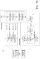
- FIG. 7A is a view schematically illustrating a scene extractor 410 for first pre-training according to an embodiment of the disclosure.
- FIG. 7B is a view schematically illustrating an acoustic scene classification (ASC) using an instance generator applied to the scene extractor 410 according to an embodiment of the disclosure.
- FIG. 7C is a detailed view of an instance generator applied to the scene extractor 410 according to an embodiment of the disclosure.
- ASC acoustic scene classification
- the scene extractor 410 may receive a sound source and output a scene information vector i scene .
- input y is the input signal to the microphone, and is the vector of1 ⁇ T
- i scene is scene information extracted from input y of the microphone and may have a 128-dimension vector form.
- the classifier 411 may receive the scene information vector i scene from the scene extractor 410 and classify the target scene, and output the scene determination probability vector ô scene ⁇ ô scene may be an m-dimension one-hot vector representing m target scenes.
- the scene extractor 410 may perform training using the sum of the instance-level BCE loss of the one-hot vector representing the target sound source and the weighted BCE loss of the final estimated one-hot vector.
- ⁇ means the weight
- p means, for example, the answer or the label
- p ⁇ means the prediction probability value.
- the weighted binary cross entropy may be a variation of the binary cross entropy (BCE).
- BCE binary cross entropy
- the BCE may be used as a loss that minimizes the penalty given when the difference between the actual label and the estimated probability is large in the binary classification problem.
- the weighted BCE may be a loss used given a weight to correct the difference in number between positive class and negative class.
- the scene extractor 410 may generate and output the instance vector which is the scene information vector corresponding to the scene information based on the obtained mixed sound source.
- the input signal is an input signal to the microphone and is a 1X160000 vector corresponding to a length of 10 seconds.
- the instance vector may be generated from the 10-second input and the scene may be estimated using the same.
- the scene extractor 410 of the system implemented in the electronic device may be a module obtained by enhancing the instance generator which is used in the multi-instance vector-based acoustic scene classification (ASC) system among scene classifies that divide pre-defined environments.
- ASC acoustic scene classification
- the acoustic scene may be implemented with various attributes, and be inferred by identifying a combination of some unique attributes thereof.
- the ASC system may effectively extract and cluster the attributes using a multi-instance learning (MIL) framework.
- MIL multi-instance learning
- the MIL known as one of the weakly supervised learning methods is a method that extracts the instance from the input data and infers the scene corresponding to the input data with the instance to which no label is designated.
- an MIL framework more appropriate for the ASC system may be developed by adopting the instance level loss and instance level label effective in instance extraction and clustering.
- the acoustic scene classification may be a convolution module designed to aim to recognize acoustic environment considering large contexts and a combination of acoustic events, atmosphere, room size, or culture and to completely separate a low-complexity neural network including convolution filters per dot, per frequency-side depth and per time-side depth.
- the acoustic scene classification (ASC) may generally consider a large context between complex acoustic data unlike sound separation and sound event detection processing the target event or source. Achieving effective ASC is known as a major subject of an artificial intelligence detection and classification of events and acoustic scenes (DCASE) community using the deep neural network.
- DCASE artificial intelligence detection and classification of events and acoustic scenes
- a particular sound event may represent an acoustic scene, but is not unique, and may also appear in other scenes.
- tram sound or noise generally represents a tram scene (e.g., inside a tram). However, it may also appear on pedestrians near tramways.
- a combination of acoustic events, acoustic noise, and even echoes may be part of an acoustic scene.
- CNNs may use log-mel spectrograms, mel-frequency cepstral coefficients (MFCCs), constant-Q transforms (CQTs), gammatone frequency cepstral coefficients (GFCCs), and chromatograms.
- MFCCs mel-frequency cepstral coefficients
- CQTs constant-Q transforms
- GFCCs gammatone frequency cepstral coefficients
- chromatograms chromatograms.
- GAP global average pooling
- FC layers fully connected layers
- the MIL may have a method for generating an instance vector and a method for inferring a bag-level class using an instance as key points. For example, focus may be on how to generate instance vectors to adopt an effective instance generator and instance-lever loss.
- the instance generator may be divided into two stages: feature map extractor and instance vector generator.
- the feature map extractor may adopt spatially separable convolutional layers with pointwise (PW) and depthwise (DW) convolutional layers instead of using VGG.
- PW pointwise
- DW depthwise
- the number of parameters of a standard convolutional layer may be C in ⁇ C out ⁇ K H ⁇ K W .
- the complexity may vary depending on the product of the sizes (Cin and Cout) of the input channel and the output channel and the height and width (KH and KW) of the kernel.
- depthwise separable convolution is an efficient version of the convolution filter while maintaining the receptive field, and may be implemented with two layers: depthwise convolution and pointwise convolution.
- the 3 ⁇ 3 filter may be replaced with a combination of 3 ⁇ 1 and 1 ⁇ 3 filters.
- the complexity of the spatially separable convolutional layer may be calculated only with the addition operation instead of multiplication. For example, the larger the filter size and the number of channels, the more efficient the complexity may be.
- spectrograms may show different meanings along the frequency and time axes. Therefore, the kernel of spatially separable convolution may be changed into a frequency-side kernel and a time-side kernel. According to previous studies on spatially separable convolutions in audio fields, keyword spotting and ASC tasks may be beneficial not only for enhancing performance, but also for modeling fewer parameters.
- the feature map extractor may include four completely separated convolution modules (FUSE-ConvMods) having a harmony of PW, frequency-side DW (FDW), and time-side DW (TDW) convolution layers.
- An input function may transfer several FULL Seperated convolution blocks (FUSE-ConvBlocks) with the PW convolution layer and may be pooled through a max pooling layer.
- FUSE-ConvBlocks FULL Seperated convolution blocks
- Xi, N, and fik may denote the input of the ith FUSE-ConvMod, the FUSE-ConvBlock of the ith FUSE-ConvMod, and the number of the kth block, respectively.
- the last FUSE-ConvMod may not perform pooling.
- the output of the feature map extractor may still be a tensor that creates a shape (channel, frequency, or frame).
- the instance vector generator uses an FDW convolutional layer with full-sized (e.g., fully connected) kernel to aggregate tensors along the frequency axis and obtain the shape of the output from the feature map extractor.
- FDW convolutional layers are used, followed by affine transform-preserving channels, which may then be reshaped and transposed.
- the primary objective of the MIL method is to determine whether each bag is positive or negative and the loss may be introduced by the average of the weighted binary cross entropy (BCE), which may be used to calculate the mean of BCE for each class considering imbalance between positive and negative classes.
- BCE binary cross entropy
- CE cross-entropy
- wBCEs, C, and ⁇ were adopted for the mean of wBCEs, number of classes, and loss function, which is the class imbalance coefficient, respectively, and ⁇ was set to C-1.
- each instance may be assigned a label using the bag-level ground truth.
- the following equation shows how to define instance-level labels using instance prediction.
- a positive label may be assigned, otherwise a negative label may be assigned. If the index of the maximum prediction score among the classes is equal to the correct answer for each instance, a positive label may be assigned, otherwise a negative label may be assigned.
- the positive label may be defined as a one-hot vector, and the negative label may be defined as a zero vector.
- the model may cluster individual instances and negative numbers using the mean of the weighted BCEs for the instance-level loss for the same reason as the bag-level loss. The entropy of all classes may be averaged, and bags may be averaged.
- instance-level labels may be set to any labels regardless of whether the instance is unique. Since the bag-level loss is computed as the ground truth (e.g., information that is known to be real or true), the bag-level loss may correctly guide the instance-level labels in the right direction as the training step progresses, otherwise the instance-level labels may end up being placed in the wrong label space.
- ground truth e.g., information that is known to be real or true
- FIG. 8 is a view schematically illustrating an embedding layer 420 for second pre-training according to an embodiment of the disclosure.
- the sound source input y is 1 ⁇ T vector-shaped input signal vector
- e is the embedding vector for the target sound source, for example one produced by receiving a 4-dimensional input and encoding it in a 128-dimensional vector form.
- the 4-dimensional input (v) may be a vector in any case between [0, 0, 0, 0] T and [1, 1, 1, 1] T .
- the target sound source ⁇ target is separated from the mixed sound source y and is a 1 ⁇ T -shaped output.
- the 4-dimensional input (v) corresponds to each sound source included in the designated sound source group.
- the 4-dimensional input may comprise 1's as its components when including the corresponding sound source and comprise 0's as its components when not including the corresponding sound source.
- the embedding layer 420 may learn partial embedding vectors to respectively represent four sound sources included in the designated sound source group in second pre-training. For example, the embedding layer 420 may learn partial embedding vectors corresponding to the inputs [1, 0, 0, 0] T , [0, 1, 0, 0] T , [0, 0, 1, 0] T , and [0, 0, 0, 1] T corresponding to the respective sound source.
- the designated first embedding vector (e_all) output when the 4-dimensional input (v) [1, 1, 1, 1] T is input to the embedding layer 420 may be a sum vector of partial embedding vectors.
- the embedding layer 420 may perform learning on the negative SI-SDR with the output target sound source as loss.
- s may mean the target signal (e.g., correct answer), and ⁇ may mean the output of the neural network.
- SI-SDR is a variation of SDR, and SDR is a log-scale expression of the ratio of signal to distortion and the larger the size, the less distortion.
- the metric corrected for this is SI-SDR, and the embedding layer 420 may learns to minimize SI-SDR by adding a negative sign to thereby maximize SI-SDR.
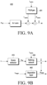
- FIG. 9A is a detailed view of a refining network 430 according to an embodiment of the disclosure.
- FIG. 9B is a view schematically illustrating a refining network 430 for third pre-training according to an embodiment of the disclosure.
- the refining network 430 may refine a first embedding vector representing an entirety of the designated sound source group into a second embedding vector representing a target sound source based on scene information.
- the refining network 430 may use feature-wise linear modulation (FiLM) used to combine information about other features containing necessary information when training a deep learning model with the deep learning model. This combination technique is called conditioning and may be used to train a deep learning model in a desired direction.
- the refining network 430 may refine the embedding vector using the scaling vector ⁇ i,c and shift vector ⁇ i , c output from the FiLM generator 431.
- FiLM F i , c ⁇ i , c ⁇ i , c ⁇ i , c F i , c + ⁇ i , c
- FiLM may pass the features to be conditioned through the respective layers, and then multiply one by the feature of the part to be conditioned as the scaling vector ⁇ i,c and add the other as the shift vector ⁇ i,c , thereby setting the direction of training the model.
- the FiLM generator 431 is a layer that generates the scaling vector and shift vector for the refining network 430, and may use various layers, such as fully connected layers and convolutional layers.
- the refining network 430 may refine the first embedding vector into the second embedding vector by using the scaling vector ⁇ scene and shift vector ⁇ scene , respectively, which are output by inputting the scene information to the FiLM generator 431.
- the embedding layer 420 trained by second pre-training when the actual target sound source is input, may output the embedding vector e bus corresponding to the target sound source to separate the target sound source from the mixed sound source input to the separation layer 440.
- the embedding layer 420 trained by the second pre-training when the target sound sources including all included in the designated sound source group are input, may output the first embedding vector e all corresponding to the entirety of the designated sound source group from the mixed sound source input to the separation layer 440.
- the refining network 430 may perform third pre-training to output the second embedding vector ê by inputting the first embedding vector e all and the scene information i scene .
- the first embedding vector e all is the embedding of all the target sound sources included in the designated sound source group, and may have the form of a 128-dimensional vector as an example.
- the scene information i scene is the output of the scene extractor trained by the first pre-training, and may have a 128-dimensional vector form as an example.
- the second embedding vector ê represents embedding for the target sound source corresponding to specific scene information i scene , and may have a 128-dimensional vector form as an example.
- the refining network 430 may be trained using the target embedding vector (e.g., embedding vector e target of the target sound source) output by inputting the target sound source to the embedding layer 420 trained by the second pre-training and the second embedding vector ê converted into from the first embedding vector based on the scene information i scene .
- the target embedding vector e.g., embedding vector e target of the target sound source
- the refining network 430 may perform learning using the MSE between the second embedding vector ê refined from the first embedding vector based on the scene information and the target embedding vector (e.g., the embedding vector e target of the target sound source) for the actual target sound source.
- s may correspond to the target signal
- ⁇ may correspond to the output of the neural network
- FIG. 10 is a table regarding the correlation between each piece of scene information and each target sound source according to an embodiment of the disclosure.
- the vertical axis indicates various scene information
- the horizontal axis indicates various target sound sources included in a designated sound source group.
- four sources (vehicle_horn_and_car_horn_and_honking, fire alarm, police car and speech- child, female, male) may be included in the target sound source to be separated, and the others (bark, bicycle _bell, bus, car_passing_by, machine gun, 35otorcycle, subway_and_metro_and_underground, wind and walk, footstep) may be other sound sources than the target sound source.
- the FSD50k dataset corresponding to the target sound event was mixed with TAU-urban acoustic 2020 mobile (TAU 2020), which is an ASC dataset corresponding to the scene background, and used.
- TAU 2020 TAU-urban acoustic 2020 mobile
- data recorded by device A in TAU2020 was used, among which Bus, Metro, Metro station, Park, or Street traffic was used.
- the sound event data is noisy and contributes to the degradation of separation performance, it was pre-refined to leave and mix only the target sound source.
- the Scaper tool acoustic scenes and sound sources were mixed.
- the number of sound sources was set to 1 to 4 (including 1 to 2 target sound sources), the SNR to -3 to 3 dB, and the sampling rate to 16 kHz.
- 10,000 train sets, 2,000 validation sets, and 1,000 test sets were generated, and a total of 50,000 train sets, 10,000 validation sets, and 5,000 test sets were generated for training and evaluation.
- the target sound sources to be separated may be vehicle_horn_and_car_horn_and_honking, police car and speech- child, female, male.
- target sound sources to be separated may be fire alarm and speech- child, female, and male.
- target sound sources to be separated may be fire alarm and speech- child, female, and male.
- target sound sources to be separated may be speech- child, female, and male.
- target sound sources to be separated may be vehicle _horn_and_car_horn_and_honking and police car.
- the separation layer may perform a fourth pre-training process to be trained to separate the target sound source based on the input sound source and the second embedding vector.
- the separation layer may separate the target sound source from the mixed sound source by refined embedding for the sound source designated as occurable in a designated specific scene through the pre-trained embedding layer, scene extractor, and refining network.
- the separation layer may be trained through joint training along with other system components. For example, as the input for the fourth pre-training of the separation layer, only the mixed sound source input was used, and training may be performed using the negative SI-SDR with the target sound source as the loss.
- the acoustic separation system may perform measurement using segmental SI-SDRi corresponding to the SI-SDR enhancement value in the range where the actual target sound source is present.
- the method used for comparative evaluation is an algorithm that excludes refining according to scenes in the method proposed herein, and may have a similar form to the conventional sound selector-based multi-sound extracting method.
- Table 1 shows the results of comparison in acoustic scenewise separation performance between the method proposed in the disclosure and the control group. Referring to Table 1, although there is a slight difference for each scene, the overall average performance is slightly higher.
- Segmental SI-SDRi (dB) Bus Metro Metrostation Park Street traffic Average Proposed method 15.33 13.75 12.21 11.83 9.6 12.54
- Control group 15.34 15.55 11.87 11.16 10.09 12.40
- Table 2 shows comparison of results when performing joint training (e.g., fourth pre-training process) using the embedding layer by the second pre-training rather than training the layer with randomly initialized parameters while joint-training the separation layer.
- joint training e.g., fourth pre-training process
- Table 2 shows comparison of results when performing joint training (e.g., fourth pre-training process) using the embedding layer by the second pre-training rather than training the layer with randomly initialized parameters while joint-training the separation layer.
- joint training e.g., fourth pre-training process
- Table 3 shows comparison in performance depending on how to condition the model in the training step.
- Baseline is the model (12 times/12 times) resultant when all separation layers are conditioned in the second pre-training and fourth pre-training.
- Method 1 and Method 2 are models modified based on conditioning on a single point.
- Method 1 is a model (12 times/1 time) obtained by conditioning all the layers in the second pre-training and conditioning on a single point in the fourth pre-training
- Method 2 is a model (1 time/1 time) trained by conditioning on a single point in both the second pre-training and fourth pre-training.
- a method 300a, 300b for separating a target sound source may comprise obtaining 360 a mixed sound source including at least one sound source.
- the method 300a, 300b for separating the target sound source may comprise obtaining 370 scene information related to the mixed sound source, based on the mixed sound source.
- the method 300a, 300b for separating the target sound source may comprise converting 380 a first embedding vector corresponding to a designated sound source group into a second embedding vector, based on the scene information.
- the method 300a, 300b for separating the target sound source may comprise separating 390 the target sound source from the mixed sound source, based on the mixed sound source and the second embedding vector.
- the method 300a, 300b for separating the target sound source may comprise performing 320 a first pre-training process to learn a scene information vector based on obtaining an input sound source.
- the obtaining 370 the scene information may comprise outputting the scene information vector based on the mixed sound source.
- the performing 320 the first pre-training process may comprise outputting the scene information vector based on the obtaining of the input sound source and learning to classify a designated scene based on the output scene information vector.
- the obtaining 370 the scene information may comprise generating an instance vector corresponding to the scene information based on the mixed sound source.
- the first embedding vector may corresponds to an entirety of the designated sound source group.
- the converting 380 the first embedding vector into the second embedding vector may comprise converting the first embedding vector into the second embedding vector corresponding to at least a portion of the designated sound source group based on the scene information.
- the method 300a, 300b for separating the target sound source may further comprise performing 330 a second pre-training process to learn partial embedding vectors, each of the partial embedding vectors corresponding to a respective sound source included in the designated sound source group.
- the first embedding vector may be a sum vector of the partial embedding vectors.
- the converting 380 the first embedding vector into the second embedding vector may comprise identifying the target sound source included in the designated sound source group corresponding to the scene information and converting the first embedding vector into the second embedding vector to correspond to the target sound source.
- the designated sound source group may include at least one target sound source designated to correspond to the scene information.
- the method 300a, 300b for separating the target sound source may further comprise performing 340 a third pre-training process to learn the conversion from the first embedding vector into the second embedding vector, based on an embedding vector between specific scene information and a specific target sound source corresponding to the specific scene information.
- the separating 390 the target sound source may comprise generating the target sound source having a vector form with the same size as the mixed sound source by applying the second embedding vector to the mixed sound source.
- an electronic device 101, 200 may comprise an input interface 220, a memory 230 storing at least one instruction, and at least one processor 210 operatively connected with the input interface 220 and the memory 230.
- the at least one processor 210 may be configured to obtain a mixed sound source including at least one sound source from the input interface 220.
- the at least one processor 210 may be configured to execute the at least one instruction, obtain scene information related to the mixed sound source, based on the mixed sound source.
- the at least one processor 210 may be configured to execute the at least one instruction, convert a first embedding vector corresponding to a designated sound source group into a second embedding vector, based on the scene information.
- the at least one processor 210 may be configured to execute the at least one instruction, separate a target sound source from the mixed sound source, based on the mixed sound source and the second embedding vector.
- the at least one processor 210 may be further configured to execute the at least one instruction, perform a first pre-training process to learn a scene information vector based on obtaining an input sound source.
- the at least one processor 210 may be further configured to execute the at least one instruction, as at least part of the obtaining the scene information, output the scene information vector based on the mixed sound source.
- the at least one processor 210 may be further configured to execute the at least one instruction, as at least part of the performing the first pre-training process, output the scene information vector based on the obtaining of the input sound source and learn to classify a designated scene based on the output scene information vector.
- the at least one processor 210 may be further configured to execute the at least one instruction, as at least part of the obtaining the scene information, generate an instance vector corresponding to the scene information based on the mixed sound source.
- the first embedding vector may correspond to an entirety of the designated sound source group.
- the at least one processor 210 may be configured to execute the at least one instruction, as at least part of the converting the first embedding vector into the second embedding vector, convert the first embedding vector into the second embedding vector corresponding to at least a portion of the designated sound source group based on the scene information.
- the at least one processor 210 may be further configured to execute the at least one instruction, perform a second pre-training process to learn partial embedding vectors, each of the partial embedding vectors corresponding to a respective sound source included in the designated sound source group.
- the first embedding vector may be a sum vector of the partial embedding vectors.
- the at least one processor 210 may be further configured to execute the at least one instruction, as at least part of the converting the first embedding vector into the second embedding vector, identify the target sound source included in the designated sound source group corresponding to the scene information and convert the first embedding vector into the second embedding vector to correspond to the target sound source.
- the designated sound source group may include at least one target sound source designated to correspond to the scene information.
- the at least one processor 210 may be further configured execute the at least one instruction, to perform a third pre-training process to learn the conversion from the first embedding vector into the second embedding vector, based on an embedding vector between specific scene information and a specific target sound source corresponding to the specific scene information.
- the at least one processor 210 may be further configured to execute the at least one instruction, as at least part of the separating the target sound source, generate the target sound source having a vector form with the same size as the mixed sound source by applying the second embedding vector to the mixed sound source.
- a non-transitory computer-readable storage medium storing one or more programs may comprise obtaining a mixed sound source including at least one sound source.
- the storage medium may comprise obtaining scene information related to the mixed sound source, based on the mixed sound source;
- the storage medium may comprise converting a first embedding vector corresponding to a designated sound source group into a second embedding vector, based on the scene information.
- the storage medium may comprise separating the target sound source from the mixed sound source, based on the mixed sound source and the second embedding vector.
Landscapes
- Engineering & Computer Science (AREA)
- Physics & Mathematics (AREA)
- Theoretical Computer Science (AREA)
- Health & Medical Sciences (AREA)
- Evolutionary Computation (AREA)
- Computational Linguistics (AREA)
- Artificial Intelligence (AREA)
- Software Systems (AREA)
- Multimedia (AREA)
- Signal Processing (AREA)
- Audiology, Speech & Language Pathology (AREA)
- Human Computer Interaction (AREA)
- Computing Systems (AREA)
- General Physics & Mathematics (AREA)
- Acoustics & Sound (AREA)
- Mathematical Physics (AREA)
- Data Mining & Analysis (AREA)
- General Engineering & Computer Science (AREA)
- General Health & Medical Sciences (AREA)
- Biophysics (AREA)
- Biomedical Technology (AREA)
- Molecular Biology (AREA)
- Life Sciences & Earth Sciences (AREA)
- Medical Informatics (AREA)
- Computer Vision & Pattern Recognition (AREA)
- Databases & Information Systems (AREA)
- Quality & Reliability (AREA)
- Telephone Function (AREA)
Abstract
Description
- The disclosure relates to a method for separating a target sound source from a mixed sound source using scene information about a mixed sound source and an electronic device thereof.
- As phone calling, recording of external voice, or capturing video using a portable digital device is commonplace, a microphone may be used to obtain sound in various digital devices, such as consumer electronics (CE) devices and mobile phones. However, the sound obtained by the microphone may include a plurality of sound sources that include background noise or other sounds not pertinent to a phone or video call.
- Sound source separation technology may be used to separate two or more sounds for each sound source. For example, sound source separation technology may be used to extract only the singer's voice from stereo music or separate two or more audio signals recorded with one microphone. Sound source separation technology may also be used for noise canceling in vehicles or mobile phones.
- Sound source separation technology may perform recording using several microphones, and then separate sound sources using the correlation between the signals obtained by the microphones. Meanwhile, methods for adopting artificial intelligence in sound source separation technology are being introduced. Some of these methods perform voice separation using pre-trained voices or noise patterns, or statistical data information.
- According to an embodiment of the disclosure, a method for separating a target sound source may comprise obtaining a mixed sound source including at least one sound source, obtaining, based on the mixed sound source, scene information related to the mixed sound source, converting, based on the scene information, a first embedding vector corresponding to a designated sound source group into a second embedding vector, and separating, based on the mixed sound source and the second embedding vector, the target sound source from the mixed sound source.
- According to an embodiment of the disclosure, an electronic device may comprise an input interface, a memory storing at least one instruction, and at least one processor operatively connected with the input interface and the memory. The at least one processor may be configured to execute the at least one instruction to, obtain a mixed sound source including at least one sound source from the input interface, obtain, based on the mixed sound source, scene information related to the mixed sound source, convert, based on the scene information, a first embedding vector corresponding to a designated sound source group into a second embedding vector, and separate, based on the mixed sound source and the second embedding vector, a target sound source from the mixed sound source.
- According to an embodiment of the disclosure, a non-transitory computer-readable storage medium storing one or more programs may comprise, based on execution of an application, obtaining a mixed sound source including at least one sound source, obtaining, based on the mixed sound source, scene information related to the mixed sound source, converting, based on the scene information, a first embedding vector corresponding to a designated sound source group into a second embedding vector, and separating, based on the obtained mixed sound source and the second embedding vector, the target sound source from the mixed sound source.
- The above and other aspects, features, and advantages of certain embodiments of the present disclosure will be more apparent from the following description taken in conjunction with the accompanying drawings.
-
FIG. 1 is a block diagram illustrating an electronic device in a network environment according to an embodiment of the disclosure; -
FIG. 2 is a block diagram illustrating an electronic device according to an embodiment of the disclosure; -
FIGS. 3A and3B are flowcharts illustrating a method for separating a target sound source according to an embodiment of the disclosure; -
FIG. 4 is a view schematically illustrating a system for separating a target sound source according to an embodiment of the disclosure; -
FIG. 5 is a block diagram illustrating a pre-training state of a system for separating a target sound source according to an embodiment of the disclosure; -
FIG. 6 is a block diagram illustrating a target separating state of a system for separating a target sound source according to an embodiment of the disclosure; -
FIG. 7A is a view schematically illustrating a scene extractor for first pre-training according to an embodiment of the disclosure; -
FIG. 7B is a view schematically illustrating an acoustic scene classification (ASC) system using an instance generator according to an embodiment of the disclosure; -
FIG. 7C is a detailed view of an instance generator according to an embodiment of the disclosure; -
FIG. 8 is a view schematically illustrating an embedding layer for second pre-training according to an embodiment of the disclosure; -
FIG. 9A is a detailed view of a refining network according to an embodiment of the disclosure; -
FIG. 9B is a view schematically illustrating a refining network for third pre-training according to an embodiment of the disclosure; and -
FIG. 10 is a table regarding the correlation between each piece of scene information and each target sound source according to an embodiment of the disclosure. -
FIG. 1 is a block diagram illustrating anelectronic device 101 in anetwork environment 100 according to an embodiment of the disclosure. - Referring to
FIG. 1 , theelectronic device 101 in thenetwork environment 100 may communicate with at least one of anelectronic device 102 via a first network 198 (e.g., a short-range wireless communication network), or anelectronic device 104 or aserver 108 via a second network 199 (e.g., a long-range wireless communication network). According to an embodiment, theelectronic device 101 may communicate with theelectronic device 104 via theserver 108. According to an embodiment, theelectronic device 101 may include aprocessor 120,memory 130, aninput module 150, asound output module 155, adisplay module 160, anaudio module 170, asensor module 176, aninterface 177, aconnecting terminal 178, ahaptic module 179, acamera module 180, apower management module 188, abattery 189, acommunication module 190, a subscriber identification module (SIM) 196, or anantenna module 197. In an embodiment, at least one (e.g., the connecting terminal 178) of the components may be omitted from theelectronic device 101, or one or more other components may be added in theelectronic device 101. According to an embodiment, some (e.g., thesensor module 176, thecamera module 180, or the antenna module 197) of the components may be integrated into a single component (e.g., the display module 160). - The
processor 120 may execute, for example, software (e.g., a program 140) to control at least one other component (e.g., a hardware or software component) of theelectronic device 101 coupled with theprocessor 120, and may perform various data processing or computation. According to an embodiment, as at least part of the data processing or computation, theprocessor 120 may store a command or data received from another component (e.g., thesensor module 176 or the communication module 190) involatile memory 132, process the command or the data stored in thevolatile memory 132, and store resulting data innon-volatile memory 134. According to an embodiment, theprocessor 120 may include a main processor 121 (e.g., a central processing unit (CPU) or an application processor (AP)), or an auxiliary processor 123 (e.g., a graphics processing unit (GPU), a neural processing unit (NPU), an image signal processor (ISP), a sensor hub processor, or a communication processor (CP)) that is operable independently from, or in conjunction with, themain processor 121. For example, when theelectronic device 101 includes themain processor 121 and theauxiliary processor 123, theauxiliary processor 123 may be configured to use lower power than themain processor 121 or to be specified for a designated function. Theauxiliary processor 123 may be implemented as separate from, or as part of themain processor 121. - The
auxiliary processor 123 may control at least some of functions or states related to at least one component (e.g., thedisplay module 160, thesensor module 176, or the communication module 190) among the components of theelectronic device 101, instead of themain processor 121 while themain processor 121 is in an inactive (e.g., sleep) state, or together with themain processor 121 while themain processor 121 is in an active state (e.g., executing an application). According to an embodiment, the auxiliary processor 123 (e.g., an image signal processor or a communication processor) may be implemented as part of another component (e.g., thecamera module 180 or the communication module 190) functionally related to theauxiliary processor 123. According to an embodiment, the auxiliary processor 123 (e.g., the neural processing unit) may include a hardware structure specified for artificial intelligence model processing. The artificial intelligence model may be generated via machine learning. Such learning may be performed, e.g., by theelectronic device 101 where the artificial intelligence is performed or via a separate server (e.g., the server 108). Learning algorithms may include, but are not limited to, e.g., supervised learning, unsupervised learning, semi-supervised learning, or reinforcement learning. The artificial intelligence model may include a plurality of artificial neural network layers. The artificial neural network may be a deep neural network (DNN), a convolutional neural network (CNN), a recurrent neural network (RNN), a restricted Boltzmann machine (RBM), a deep belief network (DBN), a bidirectional recurrent deep neural network (BRDNN), deep Q-network or a combination of two or more thereof but is not limited thereto. The artificial intelligence model may, additionally or alternatively, include a software structure other than the hardware structure. - The
memory 130 may store various data used by at least one component (e.g., theprocessor 120 or the sensor module 176) of theelectronic device 101. The various data may include, for example, software (e.g., the program 140) and input data or output data for a command related thereto. Thememory 130 may include thevolatile memory 132 or thenon-volatile memory 134. - The
program 140 may be stored in thememory 130 as software, and may include, for example, an operating system (OS) 142,middleware 144, or anapplication 146. - The
input module 150 may receive a command or data to be used by other component (e.g., the processor 120) of theelectronic device 101, from the outside (e.g., a user) of theelectronic device 101. Theinput module 150 may include, for example, a microphone, a mouse, a keyboard, keys (e.g., buttons), or a digital pen (e.g., a stylus pen). - The
sound output module 155 may output sound signals to the outside of theelectronic device 101. Thesound output module 155 may include, for example, a speaker or a receiver. The speaker may be used for general purposes, such as playing multimedia or playing record. The receiver may be used for receiving incoming calls. According to an embodiment, the receiver may be implemented as separate from, or as part of the speaker. - The
display module 160 may visually provide information to the outside (e.g., a user) of theelectronic device 101. Thedisplay 160 may include, for example, a display, a hologram device, or a projector and control circuitry to control a corresponding one of the display, hologram device, and projector. According to an embodiment, thedisplay 160 may include a touch sensor configured to detect a touch, or a pressure sensor configured to measure the intensity of a force generated by the touch. - The
audio module 170 may convert a sound into an electrical signal and vice versa. According to an embodiment, theaudio module 170 may obtain the sound via theinput module 150, or output the sound via thesound output module 155 or a headphone of an external electronic device (e.g., an electronic device 102) directly (e.g., wiredly) or wirelessly coupled with theelectronic device 101. - The
sensor module 176 may detect an operational state (e.g., power or temperature) of theelectronic device 101 or an environmental state (e.g., a state of a user) external to theelectronic device 101, and then generate an electrical signal or data value corresponding to the detected state. According to an embodiment, thesensor module 176 may include, for example, a gesture sensor, a gyro sensor, an atmospheric pressure sensor, a magnetic sensor, an accelerometer, a grip sensor, a proximity sensor, a color sensor, an infrared (IR) sensor, a biometric sensor, a temperature sensor, a humidity sensor, or an illuminance sensor. - The
interface 177 may support one or more specified protocols to be used for theelectronic device 101 to be coupled with the external electronic device (e.g., the electronic device 102) directly (e.g., wiredly) or wirelessly. According to an embodiment, theinterface 177 may include, for example, a high definition multimedia interface (HDMI), a universal serial bus (USB) interface, a secure digital (SD) card interface, or an audio interface. - A connecting
terminal 178 may include a connector via which theelectronic device 101 may be physically connected with the external electronic device (e.g., the electronic device 102). According to an embodiment, the connectingterminal 178 may include, for example, a HDMI connector, a USB connector, a SD card connector, or an audio connector (e.g., a headphone connector). - The
haptic module 179 may convert an electrical signal into a mechanical stimulus (e.g., a vibration or motion) or electrical stimulus which may be recognized by a user via his tactile sensation or kinesthetic sensation. According to an embodiment, thehaptic module 179 may include, for example, a motor, a piezoelectric element, or an electric stimulator. - The
camera module 180 may capture a still image or moving images. According to an embodiment, thecamera module 180 may include one or more lenses, image sensors, image signal processors, or flashes. - The
power management module 188 may manage power supplied to theelectronic device 101. According to an embodiment, thepower management module 188 may be implemented as at least part of, for example, a power management integrated circuit (PMIC). - The
battery 189 may supply power to at least one component of theelectronic device 101. According to an embodiment, thebattery 189 may include, for example, a primary cell which is not rechargeable, a secondary cell which is rechargeable, or a fuel cell. - The
communication module 190 may support establishing a direct (e.g., wired) communication channel or a wireless communication channel between theelectronic device 101 and the external electronic device (e.g., theelectronic device 102, theelectronic device 104, or the server 108) and performing communication via the established communication channel. Thecommunication module 190 may include one or more communication processors that are operable independently from the processor 120 (e.g., the application processor (AP)) and supports a direct (e.g., wired) communication or a wireless communication. According to an embodiment, thecommunication module 190 may include a wireless communication module 192 (e.g., a cellular communication module, a short-range wireless communication module, or a global navigation satellite system (GNSS) communication module) or a wired communication module 194 (e.g., a local area network (LAN) communication module or a power line communication (PLC) module). A corresponding one of these communication modules may communicate with the externalelectronic device 104 via a first network 198 (e.g., a short-range communication network, such as Bluetooth™, wireless-fidelity (Wi-Fi) direct, or infrared data association (IrDA)) or a second network 199 (e.g., a long-range communication network, such as a legacy cellular network, a 5G network, a next-generation communication network, the Internet, or a computer network (e.g., local area network (LAN) or wide area network (WAN)). These various types of communication modules may be implemented as a single component (e.g., a single chip), or may be implemented as multi components (e.g., multi chips) separate from each other. Thewireless communication module 192 may identify or authenticate theelectronic device 101 in a communication network, such as thefirst network 198 or thesecond network 199, using subscriber information (e.g., international mobile subscriber identity (IMSI)) stored in thesubscriber identification module 196. - The
wireless communication module 192 may support a 5G network, after a 4G network, and next-generation communication technology, e.g., new radio (NR) access technology. The NR access technology may support enhanced mobile broadband (eMBB), massive machine type communications (mMTC), or ultra-reliable and low-latency communications (URLLC). Thewireless communication module 192 may support a high-frequency band (e.g., the mmWave band) to achieve, e.g., a high data transmission rate. Thewireless communication module 192 may support various technologies for securing performance on a high-frequency band, such as, e.g., beamforming, massive multiple-input and multiple-output (massive MIMO), full dimensional MIMO (FD-MIMO), array antenna, analog beamforming, or large scale antenna. Thewireless communication module 192 may support various requirements specified in theelectronic device 101, an external electronic device (e.g., the electronic device 104), or a network system (e.g., the second network 199). According to an embodiment, thewireless communication module 192 may support a peak data rate (e.g., 20Gbps or more) for implementing eMBB, loss coverage (e.g., 164dB or less) for implementing mMTC, or U-plane latency (e.g., 0.5ms or less for each of downlink (DL) and uplink (UL), or a round trip of 1ms or less) for implementing URLLC. - The
antenna module 197 may transmit or receive a signal or power to or from the outside (e.g., the external electronic device). According to an embodiment, theantenna module 197 may include one antenna including a radiator formed of a conductive body or conductive pattern formed on a substrate (e.g., a printed circuit board (PCB)). According to an embodiment, theantenna module 197 may include a plurality of antennas (e.g., an antenna array). In this case, at least one antenna appropriate for a communication scheme used in a communication network, such as thefirst network 198 or thesecond network 199, may be selected from the plurality of antennas by, e.g., thecommunication module 190. The signal or the power may then be transmitted or received between thecommunication module 190 and the external electronic device via the selected at least one antenna. According to an embodiment, other parts (e.g., radio frequency integrated circuit (RFIC)) than the radiator may be further formed as part of theantenna module 197. - According to an embodiment, the
antenna module 197 may form a mmWave antenna module. According to an embodiment, the mmWave antenna module may include a printed circuit board, a RFIC disposed on a first surface (e.g., the bottom surface) of the printed circuit board, or adjacent to the first surface and capable of supporting a designated high-frequency band (e.g., the mmWave band), and a plurality of antennas (e.g., array antennas) disposed on a second surface (e.g., the top or a side surface) of the printed circuit board, or adjacent to the second surface and capable of transmitting or receiving signals of the designated high-frequency band. - At least some of the above-described components may be coupled mutually and communicate signals (e.g., commands or data) therebetween via an inter-peripheral communication scheme (e.g., a bus, general purpose input and output (GPIO), serial peripheral interface (SPI), or mobile industry processor interface (MIPI)).
- According to an embodiment, commands or data may be transmitted or received between the
electronic device 101 and the externalelectronic device 104 via theserver 108 coupled with thesecond network 199. The externalelectronic devices electronic device 101. According to an embodiment, all or some of operations to be executed at theelectronic device 101 may be executed at one or more of the externalelectronic devices electronic device 101 should perform a function or a service automatically, or in response to a request from a user or another device, theelectronic device 101, instead of, or in addition to, executing the function or the service, may request the one or more external electronic devices to perform at least part of the function or the service. The one or more external electronic devices receiving the request may perform the at least part of the function or the service requested, or an additional function or an additional service related to the request, and transfer an outcome of the performing to theelectronic device 101. Theelectronic device 101 may provide the outcome, with or without further processing of the outcome, as at least part of a reply to the request. To that end, a cloud computing, distributed computing, mobile edge computing (MEC), or client-server computing technology may be used, for example. Theelectronic device 101 may provide ultra low-latency services using, e.g., distributed computing or mobile edge computing. In another embodiment, the externalelectronic device 104 may include an Internet-of-things (IoT) device. Theserver 108 may be an intelligent server using machine learning and/or a neural network. According to an embodiment, the externalelectronic device 104 or theserver 108 may be included in thesecond network 199. Theelectronic device 101 may be applied to intelligent services (e.g., smart home, smart city, smart car, or health-care) based on 5G communication technology or IoT-related technology. - The electronic device according to an embodiment of the disclosure may be one of various types of electronic devices. The electronic devices may include, for example, a portable communication device (e.g., a smart phone), a computer device, a portable multimedia device, a portable medical device, a camera, an electronic device, or a home appliance. According to an embodiment of the disclosure, the electronic devices are not limited to those described above.
- It should be appreciated that various embodiments of the present disclosure and the terms used therein are not intended to limit the technological features set forth herein to particular embodiments and include various changes, equivalents, or replacements for a corresponding embodiment. With regard to the description of the drawings, similar reference numerals may be used to refer to similar or related elements. It is to be understood that a singular form of a noun corresponding to an item may include one or more of the things, unless the relevant context clearly indicates otherwise. As used herein, each of such phrases as "A or B," "at least one of A and B," "at least one of A or B," "A, B, or C," "at least one of A, B, and C," and "at least one of A, B, or C," may include all possible combinations of the items enumerated together in a corresponding one of the phrases. As used herein, such terms as "1st" and "2nd," or "first" and "second" may be used to simply distinguish a corresponding component from another, and does not limit the components in other aspect (e.g., importance or order). It is to be understood that if an element (e.g., a first element) is referred to, with or without the term "operatively" or "communicatively", as "coupled with," "coupled to," "connected with," or "connected to" another element (e.g., a second element), it means that the element may be coupled with the other element directly (e.g., wiredly), wirelessly, or via a third element.
- As used herein, the term "module" may include a unit implemented in hardware, software, or firmware, and may interchangeably be used with other terms, for example, "logic," "logic block," "part," or "circuitry". A module may be a single integral component, or a minimum unit or part thereof, adapted to perform one or more functions. For example, according to an embodiment, the module may be implemented in a form of an application-specific integrated circuit (ASIC).
- An embodiment of the disclosure may be implemented as software (e.g., the program 140) including one or more instructions that are stored in a storage medium (e.g.,
internal memory 136 or external memory 138) that is readable by a machine (e.g., the electronic device 101). For example, a processor (e.g., the processor 120) of the machine (e.g., the electronic device 101) may invoke at least one of the one or more instructions stored in the storage medium, and execute it, with or without using one or more other components under the control of the processor. This allows the machine to be operated to perform at least one function according to the at least one instruction invoked. The one or more instructions may include a code generated by a complier or a code executable by an interpreter. The machine-readable storage medium may be provided in the form of a non-transitory storage medium. Wherein, the term "non-transitory" simply means that the storage medium is a tangible device, and does not include a signal (e.g., an electromagnetic wave), but this term does not differentiate between where data is semi-permanently stored in the storage medium and where the data is temporarily stored in the storage medium. - According to an embodiment, a method according to various embodiments of the disclosure may be included and provided in a computer program product. The computer program products may be traded as commodities between sellers and buyers. The computer program product may be distributed in the form of a machine-readable storage medium (e.g., compact disc read only memory (CD-ROM)), or be distributed (e.g., downloaded or uploaded) online via an application store (e.g., Play Store™), or between two user devices (e.g., smart phones) directly. If distributed online, at least part of the computer program product may be temporarily generated or at least temporarily stored in the machine-readable storage medium, such as memory of the manufacturer's server, a server of the application store, or a relay server.
- According to an embodiment, each component (e.g., a module or a program) of the above-described components may include a single entity or multiple entities. Some of the plurality of entities may be separately disposed in different components. According to various embodiments, one or more of the above-described components may be omitted, or one or more other components may be added. Alternatively or additionally, a plurality of components (e.g., modules or programs) may be integrated into a single component. In such a case, according to various embodiments, the integrated component may still perform one or more functions of each of the plurality of components in the same or similar manner as they are performed by a corresponding one of the plurality of components before the integration. According to various embodiments, operations performed by the module, the program, or another component may be carried out sequentially, in parallel, repeatedly, or heuristically, or one or more of the operations may be executed in a different order or omitted, or one or more other operations may be added.
-
FIG. 2 is a block diagram illustrating anelectronic device 200 according to an embodiment of the disclosure. - Referring to
FIG. 2 , according to an embodiment, an electronic device 200 (e.g., theelectronic device 101 ofFIG. 1 ) may include aninput interface 220, amemory 230, and/or aprocessor 210. As an example, theinput interface 220 may be a portion of an input module (e.g., theinput module 150 ofFIG. 1 ) that receives sound data from a source external to the electronic device (e.g., the user) and may be, for example, a microphone. - According to an embodiment, the memory 230 (e.g., the
memory 130 ofFIG. 1 ) may store various commands or data used by at least one component (e.g., theprocessor 120 or thesensor module 176 ofFIG. 1 ) of theelectronic device 200. According to an embodiment, thememory 230 may include a non-volatile memory, a volatile memory, a flash memory, a hard disk drive (HDD) or a solid state drive (SDD). Thememory 230 may be accessed by theprocessor 210, and data read/record/modify/delete/update may be carried out by theprocessor 210. - According to an embodiment, the processor 210 (e.g., the
processor 120 ofFIG. 1 ) may execute the commands or operations stored in thememory 230. Specific commands or operations of theprocessor 210 are described below. - According to an embodiment, the
processor 210 may train a neural network using a program stored in thememory 230. For example, theprocessor 210 may train the neural network for generating a pre-defined scene information vector based on obtaining an input sound source, generating a partial embedding vector corresponding to each target sound source included in a designated sound source group, or generating an embedding vector based on an embedding vector between specific scene information and a specific target sound source. The neural network may be designed to emulate the high learning capacity of the human brain on the computer and may include a plurality of weighted network nodes which emulate the neurons of the human neural network. The plurality of network nodes may send and receive data according to their respective connection relationships so as to simulate the synaptic activity of neurons that send and receive signals through synapses. For example, the neural network may include a deep learning model developed from the neural network model. In a deep learning model, a plurality of network nodes may be located in different layers and exchange data according to a convolutional connection relationship. Examples of neural network models include a deep neural network (DNN), a convolutional neural network (CNN), a recurrent neural network, a restricted Boltzmann machine, a deep belief network, a deep Q-Network, or such various deep learning schemes and may be applied in fields such as vision recognition, speech recognition, natural language processing, and voice/signal processing. - According to an embodiment, the
processor 210 may be a general-purpose processor (e.g., CPU), may be an AI-dedicated processor (e.g., GPU) for artificial intelligence learning, or may be any other processor structure known to one of ordinary skill in the art. - According to an embodiment, the
memory 230 may store the neural network model generated through the learning algorithm for classifying or recognizing data. For example, thememory 230 may store a deep learning model generated as a result of learning performed by theprocessor 210. - According to an embodiment, the processor may include a data learning unit for learning the neural network for data classification or recognition. The data learning unit may learn criteria as to how to classify and recognize data using learning data as well as what learning data to use to determine data classification/recognition. The data learning unit may obtain learning data to be used for training and apply the obtained learning data to the deep learning model to train the deep learning model. The data learning unit may be manufactured in the form of at least one hardware chip (e.g., integrated circuit (IC)) which are to be equipped as part of the
processor 210. For example, the data learning unit may be implemented as software. When implemented as a software module (or program module including instructions), the software module may be stored in non-transitory computer-readable media. In this case, the at least one software module may be provided by the operating system (OS) or by an application. - According to an embodiment, the data learning unit may include a learning data obtaining unit and a model learning unit. The learning data obtaining unit may obtain learning data necessary for the neural network model for classifying and recognizing data. The model learning unit may train the neural network model to have determination criteria regarding how to classify predetermined data using the obtained learning data. In this case, the model learning unit may train the neural network model via supervised learning which uses at least part of the learning data as a reference for determination. For example, the model learning unit may train the neural network model through unsupervised learning that discovers determination criteria by being self-trained using learning data without supervision. Furthermore the model learning unit may train the neural network model through reinforcement learning using feedback about whether the result of determination of context according to learning is correct. The model learning unit may train the neural network model using learning algorithms including, for example, error back-propagation or gradient descent.
- In an embodiment, if the neural network model is trained, the model learning unit may store the trained neural network model in the
memory 230. For example, the model learning unit may store the trained neural network model in a memory of a server connected to the electronic device through a wired or wireless network. - In an embodiment, the data learning unit may pre-process the obtained data to enhance the analysis result of the recognition model, save resources or time necessary to generate the recognition model, or allow the obtained data to be used for learning for context determination. For example, the data learning unit may process the obtained data into a designated format to allow the model learning unit to use the obtained learning data for learning for image recognition. The data learning unit may select data necessary for learning from among the obtained learning data or the pre-processed learning data. The selected learning data may be provided to the model learning unit.
- In an embodiment, the data learning unit may further include a model evaluating unit to enhance the analysis result of the neural network model. The model evaluating unit may enter evaluation data to the neural network model and, when the analysis result output from the evaluation data fails to meet a predetermined reference, allow the model learning unit to re-learn. In this case, the evaluation data may be data defined to evaluate the recognition model. As an example, when the number or ratio of incorrect analysis results among the analysis results of the recognition model trained for the evaluation data exceeds a designated threshold, the model evaluating unit may evaluate that the recognition model fails to meet a predetermined reference.
- Although the
processor 210 and thememory 230 are described as functionally divided from each other, the above-described components may be integrated into a single module which may be referred to as an AI module. - The above-described artificial intelligence technology may be used in voice processing fields, such as sound source separation, voice extraction, or noise cancellation. For example, as one AI-based sound source separation technology, audio signal analysis technology and deep learning technology may be combined to separate components for each sound source and use the same to extract only a desired target sound source from a plurality of sound sources or create new content based on the separated sound source.
-
FIGS. 3A and3B areflowcharts illustrating methods FIG. 4 is a view schematically illustrating asystem 400 for separating a target sound source according to an embodiment of the disclosure. - Referring to
FIGS. 3A ,3B , and4 , according to an embodiment, asystem 400 for separating a target sound source from a plurality of sound sources may include ascene extractor 410 receiving a mixed sound source and outputting scene information, an embeddinglayer 420 learning an embedding vector corresponding to at least one target sound source included in a designated sound source group, arefining network 430 refining the learned embedding vector of the embeddinglayer 420 based on the scene information, and aseparation layer 440 separating the mixed sound source based on the refined embedding vector. - In an embodiment, in the
system 400 for separating the target sound source, a sound source signal y which may be a T-long time-domain waveform and a touchscreen vector O = [o 1, ··· , oN ] T , may be provided as inputs. For example, N may be the number of sounds (e.g., acoustic events) included in the designated sound group. For example, to extract the nth sound, the target sound vector o may be a one-hot vector, where the element (o_n) corresponding to the target sound may be set to 1, and another element (o_j) (where j is not n) may be set to 0. When the sound source signal y and the target sound vector are input, the target sound source may be estimated as x̂ = DNN(y,o). Here, nonlinear transformation of a deep neural network (DNN) may be applied. A Conv-TasNet architecture configured to separate sound sources in the time domain and extract frameworks may be used. - In an embodiment, when the sound source signal y is input, the intermediate expression H = [h 1 ,···, hF ] of the mixture of the
system 400 for separating the target sound source may be generated. For example, h_f denotes the feature of the fth frame of the D dimension, which is the dimension of the feature space, and F is the total number of frames. - If the target sound vector O = [o 1, ··· , oN ] T is input in a parallel manner, the embedding
layer 420 may apply target embedding
system 400 for separating the target sound source may separate and output only the target sound source. - In an embodiment, the
system 400 for separating the target sound source may apply the received target sound vector O = [o 1 ,··· , oN ] T to the designated embedding vector [e 1 ,··· , eN ]. In an embodiment, thesystem 400 for separating the target sound source may refine the preset embedding vector [e 1 ,··· , eN ] through the scene information about the input mixed sound source. - In an embodiment, the
methods more operations 300a for pre-training thesystem 400 for separating the target sound source and one ormore operations 300b for separating the target sound source using the trained system. - In an embodiment, the sound source obtained in
operation 310 may be a sound source for pre-training and may be the same or different from the mixed sound source described below, and may include at least one sound source. - In an embodiment, in
operations electronic device 101 ofFIG. 1 or theelectronic device 200 ofFIG. 2 ) may perform each of a first pre-training process, a second pre-training process, a third pre-training process, and a fourth pre-training process. Specific pre-training by the electronic device is described below. The electronic device may separate the target sound source from the mixed sound source after training is complete by the pre-training. - In
operation 320, a first pre-training process may be performed to learn a scene information vector. - In
operation 330, a second pre-training process may be performed to learn partial embedding vectors each corresponding to a respective sound included in a preset sound group. For example, if the preset sound group includes 3 preset sounds, 3 partial embedding vectors are learned. - In
operation 340, a third pre-training process may be performed to learn, based on an embedding vector between specific scene information and a specific sound source corresponding to specific scene information, a conversion from a first embedding vector to a second embedding vector. - In
operation 350, a fourth pre-training process may be performed to learn to separate a target sound source from a plurality of sounds based on the input sound source and a second embedding vector. - In an embodiment, in
operation 360, the electronic device may obtain a mixed sound source including at least one sound source. For example, the mixed sound source may be generated by being received from an external environment through an input interface (e.g., thecommunication module 190 ofFIG. 1 ) and be generated through the microphone (e.g., theinput interface 220 ofFIG. 2 ) included in the electronic device. In an embodiment, the electronic device may receive the mixed sound source, generated through a microphone of an external device, through the input interface. The mixed sound source may be artificially generated, or after generated, filtered or processed. - In an embodiment, the mixed sound source may include the target sound source to be separated or may include other sound sources. For example, y is the input signal corresponding to the mixed sound source, starget,n is the signal corresponding to the nth target sound source to be separated, and sother is the signal corresponding to a sound source other than the target sound source to be separated. Although the number of target sound sources is limited to two as an example, more target sound sources or other types of target sound sources may be present.

- In an embodiment, the target sound source may include at least one sound source and be represented as the following equation.

- In an embodiment, in
operation 370, the electronic device may obtain scene information related to the mixed sound source based on the obtained mixed sound source. In an embodiment, thescene extractor 410 ofFIG. 4 may receive the mixed sound source, select appropriate scene information from a designated scene information group, and output the selected scene information. Thescene extractor 410 may extract scene information corresponding to the mixed sound source from the received mixed sound source including at least one input sound source through an artificial neural network trained through the first pre-training. In the scene information included in the designated scene information group, at least one respective corresponding sound source may be preset. - In an embodiment, in
operation 380, the electronic device may convert a first embedding vector corresponding to the designated sound source group into a second embedding vector based on the obtained scene information. For example, the embeddinglayer 420 ofFIG. 4 may learn the first embedding vector corresponding to an entirety of the designated sound source group in the artificial neural network trained through the second pre-training. Therefining network 430 ofFIG. 4 may convert, through the artificial neural network trained through the third pre-training, the first embedding vector into the second embedding vector based on the obtained scene information. - In an embodiment, the embedding
layer 420 ofFIG. 4 may learn and store the first embedding vector, which is an embedding vector corresponding to the entirety of the designated sound source group. The designated sound source group may include at least one target sound source. The first embedding vector may be a sum vector of partial embedding vectors each corresponding to a respective target sound source. In the designated sound source group, at least one target sound source that may be generated in each piece of scene information included in the scene information group may be preconfigured to correspond to a respective piece of scene information. - In an embodiment, the
refining network 430 ofFIG. 4 may convert the first embedding vector into a second embedding vector corresponding to scene information using a pre-trained neural network. The second embedding vector may be an embedding vector converted into from the first embedding vector stored or pre-trained to separate the target sound source corresponding to each piece of scene information. - In an embodiment, in
operation 390, the electronic device may separate the target sound source from the obtained mixed sound source based on the refined second embedding vector. Theseparation layer 440 ofFIG. 4 may receive the mixed sound source and the second embedding vector and separate the target sound source using the pre-trained neural network. As an example, theseparation layer 440 may be represented as ŝtarget = m · y by estimating the mask m for the mixed sound source and multiplying. Here, the mask m for the mixed sound source may be estimated using the deep neural network. - In an embodiment, the
separation layer 440 ofFIG. 4 may separate the target sound source from the mixed sound source using the second embedding vector through the artificial neural network trained through the fourth pre-training process. -
FIG. 5 is a block diagram illustrating a pre-training state of a system for separating a target sound source according to an embodiment of the disclosure.FIG. 6 is a block diagram illustrating a target separating state of a system for separating a target sound source according to an embodiment of the disclosure. - Referring further to
FIGS. 5 and6 , according to an embodiment, thesystem 400 for separating the target sound source may be pre-trained to receive sound sources and output target sound sources and may then receive a mixed sound source of one or more sound sources and separate target sound sources. - For example, the number N of filters of the encoder may be set to 512, the kernel size L of the filter to 32, the number B of filters of the residual path and bottleneck layer to 128, the number H of filters in depthwise convolution to 256, the kernel size P of the convolutional block to 3, the number X of dilated convolution blocks per repeat to 6,and the number R of repeats to 2.
- In an embodiment, for the embedding
layer 420, a 4x128 matrix which uses a m-size multi-hot vector as the input and a 128-size vector as the output under the assumption that four target sound sources may be generatable, may be used. - In an embodiment, in the pre-training process of the
system 400 for separating the target sound source, vectors corresponding to generatable target sound sources corresponding to a number of all cases may be input to the embeddinglayer 420. In contrast, in a state in which thesystem 400 for separating the target sound source separates the target sound source, vectors corresponding to all target sound sources included in the designated sound source group may be input to the embeddinglayer 420. - In an embodiment, the
scene extractor 410 may be configured to define a fully-separated convolutional module (FUSE-ConvMod) composed of a combination of pointwise, frequency-side depthwise, and temporal-side depthwise convolution and allow the final output to 128 dimensions. - In an embodiment, the
refining network 430 may increase 128 dimensions to 256 dimensions using the convolution to change only the number of channels, modify the representation using the bias and weight generated from scene information through a conditioning scheme, and then change it back to have an output of 128 dimensions. - Further, training may be performed with the initial learning rate value of 10-4 by setting the batchsize to 16 upon training and making the learning rate gradually reduce using the scheduler that exponentially decreases the size to half after 2,000,000 epochs.
-
FIG. 7A is a view schematically illustrating ascene extractor 410 for first pre-training according to an embodiment of the disclosure.FIG. 7B is a view schematically illustrating an acoustic scene classification (ASC) using an instance generator applied to thescene extractor 410 according to an embodiment of the disclosure.FIG. 7C is a detailed view of an instance generator applied to thescene extractor 410 according to an embodiment of the disclosure. - Referring to
FIG. 7A , according to an embodiment, thescene extractor 410 may receive a sound source and output a scene information vector iscene. For example, input y is the input signal to the microphone, and is the vector of1 × T, and iscene is scene information extracted from input y of the microphone and may have a 128-dimension vector form. According to an embodiment, theclassifier 411 may receive the scene information vector iscene from thescene extractor 410 and classify the target scene, and output the scene determination probability vector ôscene · ôscene may be an m-dimension one-hot vector representing m target scenes. - According to an embodiment, the
scene extractor 410 may perform training using the sum of the instance-level BCE loss of the one-hot vector representing the target sound source and the weighted BCE loss of the final estimated one-hot vector. According to an embodiment, the weighted BCE may be calculated by the following equation.
- Here, α means the weight, p means, for example, the answer or the label, and p̂ means the prediction probability value. Here, the weight may be, e.g., α =9.
- The weighted binary cross entropy may be a variation of the binary cross entropy (BCE). The BCE may be used as a loss that minimizes the penalty given when the difference between the actual label and the estimated probability is large in the binary classification problem. The weighted BCE may be a loss used given a weight to correct the difference in number between positive class and negative class.
- Referring further to
FIGS. 7B and7C , in an embodiment, thescene extractor 410 may generate and output the instance vector which is the scene information vector corresponding to the scene information based on the obtained mixed sound source. For example, the input signal is an input signal to the microphone and is a 1X160000 vector corresponding to a length of 10 seconds. The instance vector may be generated from the 10-second input and the scene may be estimated using the same. - In an embodiment, the
scene extractor 410 of the system implemented in the electronic device (e.g., the processor) may be a module obtained by enhancing the instance generator which is used in the multi-instance vector-based acoustic scene classification (ASC) system among scene classifies that divide pre-defined environments. - In the acoustic scene classification (ASC) system, the acoustic scene may be implemented with various attributes, and be inferred by identifying a combination of some unique attributes thereof. In an embodiment, the ASC system may effectively extract and cluster the attributes using a multi-instance learning (MIL) framework. The MIL known as one of the weakly supervised learning methods is a method that extracts the instance from the input data and infers the scene corresponding to the input data with the instance to which no label is designated. For example, an MIL framework more appropriate for the ASC system may be developed by adopting the instance level loss and instance level label effective in instance extraction and clustering.
- In an embodiment, the acoustic scene classification (ASC) may be a convolution module designed to aim to recognize acoustic environment considering large contexts and a combination of acoustic events, atmosphere, room size, or culture and to completely separate a low-complexity neural network including convolution filters per dot, per frequency-side depth and per time-side depth. The acoustic scene classification (ASC) may generally consider a large context between complex acoustic data unlike sound separation and sound event detection processing the target event or source. Achieving effective ASC is known as a major subject of an artificial intelligence detection and classification of events and acoustic scenes (DCASE) community using the deep neural network. In an embodiment, a particular sound event may represent an acoustic scene, but is not unique, and may also appear in other scenes. For example, tram sound or noise generally represents a tram scene (e.g., inside a tram). However, it may also appear on pedestrians near tramways. For example, a combination of acoustic events, acoustic noise, and even echoes may be part of an acoustic scene. There may be no unique events or attributes, such as quiet situations or environments. These types of environments may mean that humans may recognize acoustic scenes in a park by the sound of running water and the chirping of birds. However, if there are no events, but it may be impossible to tell if a scene takes place in a park or some other exterior scene.
- In an embodiment, convolutional neural networks (CNNs) may use log-mel spectrograms, mel-frequency cepstral coefficients (MFCCs), constant-Q transforms (CQTs), gammatone frequency cepstral coefficients (GFCCs), and chromatograms. A common strategy for designing an ASC system is to extract advanced feature maps implemented as activation scores of events from raw audio data, and to classify by global average pooling (GAP) or fully connected layers (FC layers) for each scene via supervised learning methods.
- The MIL may have a method for generating an instance vector and a method for inferring a bag-level class using an instance as key points. For example, focus may be on how to generate instance vectors to adopt an effective instance generator and instance-lever loss.
- The instance generator may be divided into two stages: feature map extractor and instance vector generator. First, the feature map extractor may adopt spatially separable convolutional layers with pointwise (PW) and depthwise (DW) convolutional layers instead of using VGG. From a point of view of complexity, the number of parameters of a standard convolutional layer may be Cin · Cout · KH · KW. For example, the complexity may vary depending on the product of the sizes (Cin and Cout) of the input channel and the output channel and the height and width (KH and KW) of the kernel. As understood by one of ordinary skill in the art, depthwise separable convolution is an efficient version of the convolution filter while maintaining the receptive field, and may be implemented with two layers: depthwise convolution and pointwise convolution. The complexity of a depth-separable convolutional layer may be calculated as:

- Furthermore, there may be fully factored convolution filters in the spatially separated convolutional layer. The 3 × 3 filter may be replaced with a combination of 3 × 1 and 1 × 3 filters. The complexity of a spatially separated convolutional layer is as follows.

- When the size (Cout) of the output channel is equal to the number of filters, the complexity of the spatially separable convolutional layer may be calculated only with the addition operation instead of multiplication. For example, the larger the filter size and the number of channels, the more efficient the complexity may be.
- Unlike image data with spatial attributes, spectrograms may show different meanings along the frequency and time axes. Therefore, the kernel of spatially separable convolution may be changed into a frequency-side kernel and a time-side kernel. According to previous studies on spatially separable convolutions in audio fields, keyword spotting and ASC tasks may be beneficial not only for enhancing performance, but also for modeling fewer parameters.
- In an embodiment, the feature map extractor may include four completely separated convolution modules (FUSE-ConvMods) having a harmony of PW, frequency-side DW (FDW), and time-side DW (TDW) convolution layers. An input function may transfer several FULL Seperated convolution blocks (FUSE-ConvBlocks) with the PW convolution layer and may be pooled through a max pooling layer. Mathematically, the output used by the ith FUSE-ConvModule is as follows.


- For example, Xi, N, and fik may denote the input of the ith FUSE-ConvMod, the FUSE-ConvBlock of the ith FUSE-ConvMod, and the number of the kth block, respectively. Exceptionally, the last FUSE-ConvMod may not perform pooling.
- The output of the feature map extractor may still be a tensor that creates a shape (channel, frequency, or frame). In an embodiment, the instance vector generator uses an FDW convolutional layer with full-sized (e.g., fully connected) kernel to aggregate tensors along the frequency axis and obtain the shape of the output from the feature map extractor. Thus, (32 × 1) FDW convolutional layers are used, followed by affine transform-preserving channels, which may then be reshaped and transposed.
- As an example, instance-level loss and bag-level loss may be considered for clustering positive and negative instances. Consequently, the total loss may be expressed as Ltotal = Lbag+Lins.
- In an embodiment, in bag-level loss, the primary objective of the MIL method is to determine whether each bag is positive or negative and the loss may be introduced by the average of the weighted binary cross entropy (BCE), which may be used to calculate the mean of BCE for each class considering imbalance between positive and negative classes. Further, a test was performed using cross-entropy (CE) for bag-level loss adopted in most classifications, and the results using the average of wBCE and CE loss were compared. The following equation shows the average of wBCE and CE. Here, wBCEs, C, and α were adopted for the mean of wBCEs, number of classes, and loss function, which is the class imbalance coefficient, respectively, and α was set to C-1. If α is 1, the mean of wBCEs may be equal to the mean of BCEs without considering class imbalance.

- In an embodiment, since instances do not have labels, each instance may be assigned a label using the bag-level ground truth. The following equation shows how to define instance-level labels using instance prediction.

- If the index of the maximum prediction score among the classes is equal to the correct answer for each instance, a positive label may be assigned, otherwise a negative label may be assigned. If the index of the maximum prediction score among the classes is equal to the correct answer for each instance, a positive label may be assigned, otherwise a negative label may be assigned. The positive label may be defined as a one-hot vector, and the negative label may be defined as a zero vector. The model may cluster individual instances and negative numbers using the mean of the weighted BCEs for the instance-level loss for the same reason as the bag-level loss. The entropy of all classes may be averaged, and bags may be averaged.
- For example, at the start of training, all parameters may be set randomly and instance-level labels may be set to any labels regardless of whether the instance is unique. Since the bag-level loss is computed as the ground truth (e.g., information that is known to be real or true), the bag-level loss may correctly guide the instance-level labels in the right direction as the training step progresses, otherwise the instance-level labels may end up being placed in the wrong label space.
-
FIG. 8 is a view schematically illustrating an embeddinglayer 420 for second pre-training according to an embodiment of the disclosure. - Referring further to
FIG. 8 , according to an embodiment, the sound source input y is 1 × T vector-shaped input signal vector, and e is the embedding vector for the target sound source, for example one produced by receiving a 4-dimensional input and encoding it in a 128-dimensional vector form. The 4-dimensional input (v) may be a vector in any case between [0, 0, 0, 0]T and [1, 1, 1, 1]T. The target sound source ŝtarget is separated from the mixed sound source y and is a 1 × T -shaped output. - As an embodiment, the 4-dimensional input (v) corresponds to each sound source included in the designated sound source group. The 4-dimensional input may comprise 1's as its components when including the corresponding sound source and comprise 0's as its components when not including the corresponding sound source.
- In an embodiment, the embedding
layer 420 may learn partial embedding vectors to respectively represent four sound sources included in the designated sound source group in second pre-training. For example, the embeddinglayer 420 may learn partial embedding vectors corresponding to the inputs [1, 0, 0, 0]T, [0, 1, 0, 0]T, [0, 0, 1, 0]T, and [0, 0, 0, 1]T corresponding to the respective sound source. - In an embodiment, the designated first embedding vector (e_all) output when the 4-dimensional input (v) [1, 1, 1, 1]T is input to the embedding
layer 420 may be a sum vector of partial embedding vectors. - In an embodiment, the embedding
layer 420 may perform learning on the negative SI-SDR with the output target sound source as loss. The negative SI-SDR may be calculated by the following equation.
- For example, s may mean the target signal (e.g., correct answer), and ŝ may mean the output of the neural network. SI-SDR is a variation of SDR, and SDR is a log-scale expression of the ratio of signal to distortion and the larger the size, the less distortion. However, since it reacts sensitively to changes in signal magnitude, the metric corrected for this is SI-SDR, and the embedding
layer 420 may learns to minimize SI-SDR by adding a negative sign to thereby maximize SI-SDR. -
FIG. 9A is a detailed view of arefining network 430 according to an embodiment of the disclosure.FIG. 9B is a view schematically illustrating arefining network 430 for third pre-training according to an embodiment of the disclosure. - Referring to
FIG. 9A , according to an embodiment, therefining network 430 may refine a first embedding vector representing an entirety of the designated sound source group into a second embedding vector representing a target sound source based on scene information. - In an embodiment, the
refining network 430 may use feature-wise linear modulation (FiLM) used to combine information about other features containing necessary information when training a deep learning model with the deep learning model. This combination technique is called conditioning and may be used to train a deep learning model in a desired direction. In an embodiment, as shown in the following equation, therefining network 430 may refine the embedding vector using the scaling vector γi,c and shift vector β i,c output from theFiLM generator 431.
- In an embodiment, FiLM may pass the features to be conditioned through the respective layers, and then multiply one by the feature of the part to be conditioned as the scaling vector γi,c and add the other as the shift vector βi,c , thereby setting the direction of training the model. In an embodiment, the
FiLM generator 431 is a layer that generates the scaling vector and shift vector for therefining network 430, and may use various layers, such as fully connected layers and convolutional layers. - In an embodiment, the
refining network 430 may refine the first embedding vector into the second embedding vector by using the scaling vector γscene and shift vector βscene, respectively, which are output by inputting the scene information to theFiLM generator 431. - Referring to
FIG. 9B , in an embodiment, the embeddinglayer 420 trained by second pre-training, when the actual target sound source is input, may output the embedding vector ebus corresponding to the target sound source to separate the target sound source from the mixed sound source input to theseparation layer 440. - In an embodiment, the embedding
layer 420 trained by the second pre-training, when the target sound sources including all included in the designated sound source group are input, may output the first embedding vector eall corresponding to the entirety of the designated sound source group from the mixed sound source input to theseparation layer 440. - In an embodiment, the
refining network 430 may perform third pre-training to output the second embedding vector ê by inputting the first embedding vector eall and the scene information iscene. The first embedding vector eall is the embedding of all the target sound sources included in the designated sound source group, and may have the form of a 128-dimensional vector as an example. The scene information iscene is the output of the scene extractor trained by the first pre-training, and may have a 128-dimensional vector form as an example. The second embedding vector ê represents embedding for the target sound source corresponding to specific scene information iscene, and may have a 128-dimensional vector form as an example. - According to an embodiment, according to the third pre-training process, the
refining network 430 may be trained using the target embedding vector (e.g., embedding vector etarget of the target sound source) output by inputting the target sound source to the embeddinglayer 420 trained by the second pre-training and the second embedding vector ê converted into from the first embedding vector based on the scene information iscene. - According to an embodiment, in third pre-training process, the
refining network 430 may perform learning using the MSE between the second embedding vector ê refined from the first embedding vector based on the scene information and the target embedding vector (e.g., the embedding vector etarget of the target sound source) for the actual target sound source. MSE is the root mean square of the error and serves to reduce the overall error and may be calculated by the following equation.
- Here, s may correspond to the target signal, and ŝ may correspond to the output of the neural network.
-
FIG. 10 is a table regarding the correlation between each piece of scene information and each target sound source according to an embodiment of the disclosure. - Referring to
FIG. 10 , the vertical axis indicates various scene information, and the horizontal axis indicates various target sound sources included in a designated sound source group. On the horizontal axis, four sources (vehicle_horn_and_car_horn_and_honking, fire alarm, police car and speech- child, female, male) may be included in the target sound source to be separated, and the others (bark, bicycle _bell, bus, car_passing_by, machine gun, 35otorcycle, subway_and_metro_and_underground, wind and walk, footstep) may be other sound sources than the target sound source. - For an experiment to verify the system of the disclosure, the FSD50k dataset corresponding to the target sound event was mixed with TAU-urban acoustic 2020 mobile (TAU 2020), which is an ASC dataset corresponding to the scene background, and used. In this scenario, as the acoustic scene information, data recorded by device A in TAU2020 was used, among which Bus, Metro, Metro station, Park, or Street traffic was used. Furthermore, considering that the sound event data is noisy and contributes to the degradation of separation performance, it was pre-refined to leave and mix only the target sound source. By the Scaper tool, acoustic scenes and sound sources were mixed. In each acoustic scene, the number of sound sources was set to 1 to 4 (including 1 to 2 target sound sources), the SNR to -3 to 3 dB, and the sampling rate to 16 kHz. For each scene, 10,000 train sets, 2,000 validation sets, and 1,000 test sets were generated, and a total of 50,000 train sets, 10,000 validation sets, and 5,000 test sets were generated for training and evaluation.
- For example, in the case of bus scene information, the target sound sources to be separated may be vehicle_horn_and_car_horn_and_honking, police car and speech- child, female, male. For example, in the case of metro scene information, target sound sources to be separated may be fire alarm and speech- child, female, and male. For example, in the case of metro station scene information, target sound sources to be separated may be fire alarm and speech- child, female, and male. For example, in the case of park scene information, target sound sources to be separated may be speech- child, female, and male. For example, in the case of street traffic scene information, target sound sources to be separated may be vehicle _horn_and_car_horn_and_honking and police car.
- According to an embodiment, the separation layer may perform a fourth pre-training process to be trained to separate the target sound source based on the input sound source and the second embedding vector. For example, the separation layer may separate the target sound source from the mixed sound source by refined embedding for the sound source designated as occurable in a designated specific scene through the pre-trained embedding layer, scene extractor, and refining network. In the fourth pre-training process, the separation layer may be trained through joint training along with other system components. For example, as the input for the fourth pre-training of the separation layer, only the mixed sound source input was used, and training may be performed using the negative SI-SDR with the target sound source as the loss.
- According to an embodiment, the acoustic separation system may perform measurement using segmental SI-SDRi corresponding to the SI-SDR enhancement value in the range where the actual target sound source is present. The method used for comparative evaluation is an algorithm that excludes refining according to scenes in the method proposed herein, and may have a similar form to the conventional sound selector-based multi-sound extracting method. Table 1 below shows the results of comparison in acoustic scenewise separation performance between the method proposed in the disclosure and the control group. Referring to Table 1, although there is a slight difference for each scene, the overall average performance is slightly higher.
[Table 1] Segmental SI-SDRi (dB) Bus Metro Metrostation Park Street traffic Average Proposed method 15.33 13.75 12.21 11.83 9.6 12.54 Control group 15.34 15.55 11.87 11.16 10.09 12.40 - Furthermore, Table 2 shows comparison of results when performing joint training (e.g., fourth pre-training process) using the embedding layer by the second pre-training rather than training the layer with randomly initialized parameters while joint-training the separation layer. Using pre-trained separation layers in all scenes may enhance performance.
[Table 2] Segmental SI-SDRi (dB) Bus Metro Metrostation Park Street traffic Average Baseline 15.33 13.75 12.21 11.83 9.6 12.54 pre-trained separation layer 15.39 14.45 12.82 12.04 10.22 12.98 - Table 3 shows comparison in performance depending on how to condition the model in the training step. Baseline is the model (12 times/12 times) resultant when all separation layers are conditioned in the second pre-training and fourth pre-training.
Method 1 and Method 2 are models modified based on conditioning on a single point. For example,Method 1 is a model (12 times/1 time) obtained by conditioning all the layers in the second pre-training and conditioning on a single point in the fourth pre-training, and Method 2 is a model (1 time/1 time) trained by conditioning on a single point in both the second pre-training and fourth pre-training.[Table 3] Segmental SI-SDRi (dB) Bus Metro Metrostation Park Street traffic Average Baseline 15.33 13.75 12.21 11.83 9.6 12.54 Method 116.16 15.13 13.44 11.81 10.34 13.38 Method 2 15.55 14.27 13.01 11.36 9.83 12.81 - As a result, it may be identified that single point conditioning in the fourth pre-training may bring a meaningful enhancement in performance, and single point conditioning in the second pre-training shows better performance than that of the baseline despite a slight performance lowering. Therefore, the method for separating a target sound source according to an embodiment of the disclosure may accurately select a sound to be separated according to a scene switch so that the listener separates and listens to her desired sound in a specific scene. According to an embodiment of the disclosure, a
method method method method - According to an embodiment, the
method method - According to an embodiment, in the
method - According to an embodiment, in the
method - According to an embodiment, in the
method method - According to an embodiment, the
method method - According to an embodiment, in the
method - According to an embodiment, in the
method - According to an embodiment, the
method - According to an embodiment, in the
method - According to an embodiment of the disclosure, an
electronic device input interface 220, amemory 230 storing at least one instruction, and at least oneprocessor 210 operatively connected with theinput interface 220 and thememory 230. The at least oneprocessor 210 may be configured to obtain a mixed sound source including at least one sound source from theinput interface 220. The at least oneprocessor 210 may be configured to execute the at least one instruction, obtain scene information related to the mixed sound source, based on the mixed sound source. The at least oneprocessor 210 may be configured to execute the at least one instruction, convert a first embedding vector corresponding to a designated sound source group into a second embedding vector, based on the scene information. The at least oneprocessor 210 may be configured to execute the at least one instruction, separate a target sound source from the mixed sound source, based on the mixed sound source and the second embedding vector. - According to an embodiment, in the
electronic device processor 210 may be further configured to execute the at least one instruction, perform a first pre-training process to learn a scene information vector based on obtaining an input sound source. The at least oneprocessor 210 may be further configured to execute the at least one instruction, as at least part of the obtaining the scene information, output the scene information vector based on the mixed sound source. - According to an embodiment, in the
electronic device processor 210 may be further configured to execute the at least one instruction, as at least part of the performing the first pre-training process, output the scene information vector based on the obtaining of the input sound source and learn to classify a designated scene based on the output scene information vector. - According to an embodiment, in the
electronic device processor 210 may be further configured to execute the at least one instruction, as at least part of the obtaining the scene information, generate an instance vector corresponding to the scene information based on the mixed sound source. - According to an embodiment, in the
electronic device processor 210 may be configured to execute the at least one instruction, as at least part of the converting the first embedding vector into the second embedding vector, convert the first embedding vector into the second embedding vector corresponding to at least a portion of the designated sound source group based on the scene information. - According to an embodiment, in the
electronic device processor 210 may be further configured to execute the at least one instruction, perform a second pre-training process to learn partial embedding vectors, each of the partial embedding vectors corresponding to a respective sound source included in the designated sound source group. The first embedding vector may be a sum vector of the partial embedding vectors. - According to an embodiment, in the
electronic device processor 210 may be further configured to execute the at least one instruction, as at least part of the converting the first embedding vector into the second embedding vector, identify the target sound source included in the designated sound source group corresponding to the scene information and convert the first embedding vector into the second embedding vector to correspond to the target sound source. - According to an embodiment, in the
electronic device - According to an embodiment, in the
electronic device processor 210 may be further configured execute the at least one instruction, to perform a third pre-training process to learn the conversion from the first embedding vector into the second embedding vector, based on an embedding vector between specific scene information and a specific target sound source corresponding to the specific scene information. - According to an embodiment, in the
electronic device processor 210 may be further configured to execute the at least one instruction, as at least part of the separating the target sound source, generate the target sound source having a vector form with the same size as the mixed sound source by applying the second embedding vector to the mixed sound source. - According to an embodiment of the disclosure, a non-transitory computer-readable storage medium storing one or more programs may comprise obtaining a mixed sound source including at least one sound source. The storage medium may comprise obtaining scene information related to the mixed sound source, based on the mixed sound source; The storage medium may comprise converting a first embedding vector corresponding to a designated sound source group into a second embedding vector, based on the scene information. The storage medium may comprise separating the target sound source from the mixed sound source, based on the mixed sound source and the second embedding vector.
Claims (15)
- A method (300a, 300b) for separating a target sound source, the method comprising:obtaining (360) a mixed sound source including at least one sound source;obtaining (370), based on the mixed sound source, scene information related to the mixed sound source;converting (380), based on the scene information, a first embedding vector corresponding to a designated sound source group into a second embedding vector; andseparating (390), based on the mixed sound source and the second embedding vector, the target sound source from the mixed sound source.
- The method (300a, 300b) of claim 1, further comprising:performing (320) a first pre-training process to learn a scene information vector based on obtaining an input sound source,wherein the obtaining (370) the scene information comprises outputting the scene information vector based on the mixed sound source.
- The method (300a, 300b) of any one of claims 1 and 2, further comprising:performing (330) a second pre-training process to learn partial embedding vectors, each of the partial embedding vectors corresponding to a respective sound source included in the designated sound source group,wherein the first embedding vector is a sum vector of the partial embedding vectors.
- The method (300a, 300b) of claim 3, wherein the converting (380) the first embedding vector into the second embedding vector comprises:identifying the target sound source included in the designated sound source group corresponding to the scene information; andconverting the first embedding vector into the second embedding vector to correspond to the target sound source.
- The method (300a, 300b) of any one of claims 1 to 4, further comprising performing (340) third pre-training process, based on an embedding vector between specific scene information and a specific target sound source corresponding to the specific scene information, to learn the conversion from the first embedding vector into the second embedding vector.
- An electronic device (101, 200) comprising:an input interface (220);a memory (230) storing at least one instruction; andat least one processor (210) operatively connected with the input interface (220) and the memory (230),wherein the at least one processor (210) is configured to execute the at least one instruction:obtain, from the input interface (220), a mixed sound source including at least one sound source,obtain, based on the mixed sound source, scene information related to the mixed sound source,convert, based on the scene information, a first embedding vector corresponding to a designated sound source group into a second embedding vector, andseparate, based on the mixed sound source and the second embedding vector, a target sound source from the mixed sound source.
- The electronic device (101, 200) of claim 6, wherein the at least one processor (210) is further configured to execute the at least one instruction:perform a first pre-training process to learn a scene information vector based on obtaining an input sound source, andas at least part of the obtaining the scene information, output the scene information vector based on the mixed sound source.
- The electronic device (101, 200) of claim 7, wherein the at least one processor (210) is further configured to execute the at least one instruction: as at least part of the performing the first pre-training process, output the scene information vector based on the obtaining of the input sound source and learn to classify a designated scene based on the output scene information vector.
- The electronic device (101, 200) of any one of claims 6 to 8, wherein the at least one processor (210) is further configured to execute the at least one instruction: as at least part of the obtaining the scene information, generate an instance vector corresponding to the scene information based on the mixed sound source.
- The electronic device (101, 200) of any one of claims 6 to 9,wherein the first embedding vector corresponds to an entirety of the designated sound source group, andwherein the at least one processor (210) is further configured to execute the at least one instruction: as at least part of the converting the first embedding vector into the second embedding vector, convert the first embedding vector into the second embedding vector corresponding to at least a portion of the designated sound source group based on the scene information.
- The electronic device (101, 200) of any one of claims 6 to 10, wherein the at least one processor (210) is further configured to execute the at least one instruction: perform a second pre-training process to learn partial embedding vectors, each of the partial embedding vectors corresponding to a respective sound source included in the designated sound source group, and
wherein the first embedding vector is a sum vector of the partial embedding vectors. - The electronic device (101, 200) of claim 11, wherein the at least one processor (210) is further configured to execute the at least one instruction: as at least part of the converting the first embedding vector into the second embedding vector, identify the target sound source included in the designated sound source group corresponding to the scene information and convert the first embedding vector into the second embedding vector to correspond to the target sound source.
- The electronic device (101, 200) of any one of claims 6 to 12, wherein the designated sound source group includes at least one target sound source designated to correspond to the scene information.
- The electronic device (101, 200) of any one of claims 6 to 13, wherein the at least one processor (210) is further configured to execute the at least one instruction: perform a third pre-training process, based on an embedding vector between specific scene information and a specific target sound source corresponding to the specific scene information, to learn the conversion from the first embedding vector into the second embedding vector.
- The electronic device (101, 200) of any one of claims 6 to 14, wherein the at least one processor (210) is further configured to execute the at least one instruction: as at least part of the separating the target sound source, generate the target sound source having a vector form with the same size as the mixed sound source by applying the second embedding vector to the mixed sound source.
Applications Claiming Priority (3)
| Application Number | Priority Date | Filing Date | Title |
|---|---|---|---|
| KR20220103538 | 2022-08-18 | ||
| KR1020220125096A KR20240025427A (en) | 2022-08-18 | 2022-09-30 | Method for separating target sound source from mixed sound source and electronic device thereof |
| PCT/KR2023/010971 WO2024039102A1 (en) | 2022-08-18 | 2023-07-27 | Method for separating target sound source from mixed sound source and electronic device thereof |
Publications (2)
| Publication Number | Publication Date |
|---|---|
| EP4571741A1 true EP4571741A1 (en) | 2025-06-18 |
| EP4571741A4 EP4571741A4 (en) | 2025-07-30 |
Family
ID=89907129
Family Applications (1)
| Application Number | Title | Priority Date | Filing Date |
|---|---|---|---|
| EP23855072.7A Pending EP4571741A4 (en) | 2022-08-18 | 2023-07-27 | METHOD FOR SEPARATING A TARGET SOUND SOURCE FROM A MIXED SOUND SOURCE AND ELECTRONIC DEVICE THEREFOR |
Country Status (2)
| Country | Link |
|---|---|
| US (1) | US12424241B2 (en) |
| EP (1) | EP4571741A4 (en) |
Family Cites Families (15)
| Publication number | Priority date | Publication date | Assignee | Title |
|---|---|---|---|---|
| JP3074952B2 (en) | 1992-08-18 | 2000-08-07 | 日本電気株式会社 | Noise removal device |
| JP3434730B2 (en) | 1999-05-21 | 2003-08-11 | Necエレクトロニクス株式会社 | Voice recognition method and apparatus |
| KR100413797B1 (en) | 2001-08-23 | 2003-12-31 | 삼성전자주식회사 | Speech signal compensation method and the apparatus thereof |
| KR101456866B1 (en) | 2007-10-12 | 2014-11-03 | 삼성전자주식회사 | Method and apparatus for extracting a target sound source signal from a mixed sound |
| KR101620866B1 (en) | 2014-12-17 | 2016-05-13 | 서울대학교산학협력단 | Dictionary learning based target source separation using induction algorithm |
| KR102691543B1 (en) * | 2018-11-16 | 2024-08-02 | 삼성전자주식회사 | Electronic apparatus for recognizing an audio scene and method for the same |
| US11568731B2 (en) | 2019-07-15 | 2023-01-31 | Apple Inc. | Systems and methods for identifying an acoustic source based on observed sound |
| US10930301B1 (en) | 2019-08-27 | 2021-02-23 | Nec Corporation | Sequence models for audio scene recognition |
| KR102740717B1 (en) | 2019-08-30 | 2024-12-11 | 엘지전자 주식회사 | Artificial sound source separation method and device of thereof |
| KR102845224B1 (en) | 2019-12-09 | 2025-08-12 | 삼성전자주식회사 | Electronic apparatus and controlling method thereof |
| CN111179961B (en) | 2020-01-02 | 2022-10-25 | 腾讯科技(深圳)有限公司 | Audio signal processing method and device, electronic equipment and storage medium |
| CN111243620B (en) | 2020-01-07 | 2022-07-19 | 腾讯科技(深圳)有限公司 | Voice separation model training method and device, storage medium and computer equipment |
| US11114108B1 (en) | 2020-05-11 | 2021-09-07 | Cirrus Logic, Inc. | Acoustic source classification using hyperset of fused voice biometric and spatial features |
| KR102410850B1 (en) | 2020-08-18 | 2022-06-20 | 부산대학교 산학협력단 | Method and apparatus for extracting reverberant environment embedding using dereverberation autoencoder |
| US11257503B1 (en) | 2021-03-10 | 2022-02-22 | Vikram Ramesh Lakkavalli | Speaker recognition using domain independent embedding |
-
2023
- 2023-07-27 EP EP23855072.7A patent/EP4571741A4/en active Pending
- 2023-08-18 US US18/235,664 patent/US12424241B2/en active Active
Also Published As
| Publication number | Publication date |
|---|---|
| US20240062773A1 (en) | 2024-02-22 |
| EP4571741A4 (en) | 2025-07-30 |
| US12424241B2 (en) | 2025-09-23 |
Similar Documents
| Publication | Publication Date | Title |
|---|---|---|
| EP3706443B1 (en) | Method and apparatus for sound object following | |
| CN114141230A (en) | Electronic device, and voice recognition method and medium thereof | |
| CN113392740B (en) | A Person Re-identification System Based on Dual Attention Mechanism | |
| CN113435568A (en) | Computer-implemented method and electronic system for training neural networks | |
| US20210134274A1 (en) | Device with convolutional neural network for acquiring multiple intent words, and method thereof | |
| CN115132221B (en) | Method for separating human voice, electronic equipment and readable storage medium | |
| CN113449700A (en) | Training of video classification model, video classification method, device, equipment and medium | |
| US20220121949A1 (en) | Personalized neural network pruning | |
| US11676580B2 (en) | Electronic device for processing user utterance and controlling method thereof | |
| US20200272898A1 (en) | Electronic device for classifying classes, electronic device for providing classification model for classifying classes, and method for operating the same | |
| CN113569607A (en) | Motion recognition method, motion recognition device, motion recognition equipment and storage medium | |
| CN115035916A (en) | Noise-containing speech emotion recognition method based on deep learning | |
| CN117423341A (en) | Voiceprint recognition method, voiceprint model training method, device, equipment and medium | |
| CN115132181B (en) | Speech recognition method, device, electronic device, storage medium and program product | |
| Pham et al. | A method upon deep learning for speech emotion recognition | |
| CN114724245A (en) | CSI-based incremental learning human body action identification method | |
| CN113470653B (en) | Voiceprint recognition method, electronic device and system | |
| KR102559074B1 (en) | Method and apparatus for providing english education services to a learner terminal and a parent terminal using a neural network | |
| US12424241B2 (en) | Method for separating target sound source from mixed sound source and electronic device thereof | |
| CN115131291A (en) | Object counting model training method, device, equipment and storage medium | |
| CN117934551B (en) | Mixed reality tracking interaction system | |
| Syafalni et al. | Efficient real-time smart keyword spotting using spectrogram-based hybrid CNN-LSTM for edge system | |
| KR20240025427A (en) | Method for separating target sound source from mixed sound source and electronic device thereof | |
| Iwaki et al. | Sound-recognition method for helping us respond appropriately to sounds in daily life | |
| US20210081765A1 (en) | Efficient inferencing with fast pointwise convolution |
Legal Events
| Date | Code | Title | Description |
|---|---|---|---|
| STAA | Information on the status of an ep patent application or granted ep patent |
Free format text: STATUS: THE INTERNATIONAL PUBLICATION HAS BEEN MADE |
|
| PUAI | Public reference made under article 153(3) epc to a published international application that has entered the european phase |
Free format text: ORIGINAL CODE: 0009012 |
|
| STAA | Information on the status of an ep patent application or granted ep patent |
Free format text: STATUS: REQUEST FOR EXAMINATION WAS MADE |
|
| 17P | Request for examination filed |
Effective date: 20250313 |
|
| AK | Designated contracting states |
Kind code of ref document: A1 Designated state(s): AL AT BE BG CH CY CZ DE DK EE ES FI FR GB GR HR HU IE IS IT LI LT LU LV MC ME MK MT NL NO PL PT RO RS SE SI SK SM TR |
|
| REG | Reference to a national code |
Ref country code: DE Ref legal event code: R079 Free format text: PREVIOUS MAIN CLASS: G10L0021028000 Ipc: G10L0021030800 |
|
| A4 | Supplementary search report drawn up and despatched |
Effective date: 20250630 |
|
| RIC1 | Information provided on ipc code assigned before grant |
Ipc: G10L 21/0308 20130101AFI20250624BHEP Ipc: G06F 18/2413 20230101ALI20250624BHEP Ipc: G06N 20/00 20190101ALI20250624BHEP Ipc: G10L 25/30 20130101ALN20250624BHEP Ipc: G10L 25/51 20130101ALN20250624BHEP |
|
| DAV | Request for validation of the european patent (deleted) | ||
| DAX | Request for extension of the european patent (deleted) |