EP4571688A1 - Fuel efficiency analysis device, system including same, and operation method thereof - Google Patents
Fuel efficiency analysis device, system including same, and operation method thereof Download PDFInfo
- Publication number
- EP4571688A1 EP4571688A1 EP23853099.2A EP23853099A EP4571688A1 EP 4571688 A1 EP4571688 A1 EP 4571688A1 EP 23853099 A EP23853099 A EP 23853099A EP 4571688 A1 EP4571688 A1 EP 4571688A1
- Authority
- EP
- European Patent Office
- Prior art keywords
- electricity efficiency
- vehicle
- standard
- gain
- contribution
- Prior art date
- Legal status (The legal status is an assumption and is not a legal conclusion. Google has not performed a legal analysis and makes no representation as to the accuracy of the status listed.)
- Pending
Links
Images





Classifications
-
- G—PHYSICS
- G07—CHECKING-DEVICES
- G07C—TIME OR ATTENDANCE REGISTERS; REGISTERING OR INDICATING THE WORKING OF MACHINES; GENERATING RANDOM NUMBERS; VOTING OR LOTTERY APPARATUS; ARRANGEMENTS, SYSTEMS OR APPARATUS FOR CHECKING NOT PROVIDED FOR ELSEWHERE
- G07C5/00—Registering or indicating the working of vehicles
- G07C5/008—Registering or indicating the working of vehicles communicating information to a remotely located station
-
- B—PERFORMING OPERATIONS; TRANSPORTING
- B60—VEHICLES IN GENERAL
- B60L—PROPULSION OF ELECTRICALLY-PROPELLED VEHICLES; SUPPLYING ELECTRIC POWER FOR AUXILIARY EQUIPMENT OF ELECTRICALLY-PROPELLED VEHICLES; ELECTRODYNAMIC BRAKE SYSTEMS FOR VEHICLES IN GENERAL; MAGNETIC SUSPENSION OR LEVITATION FOR VEHICLES; MONITORING OPERATING VARIABLES OF ELECTRICALLY-PROPELLED VEHICLES; ELECTRIC SAFETY DEVICES FOR ELECTRICALLY-PROPELLED VEHICLES
- B60L15/00—Methods, circuits, or devices for controlling the traction-motor speed of electrically-propelled vehicles
- B60L15/20—Methods, circuits, or devices for controlling the traction-motor speed of electrically-propelled vehicles for control of the vehicle or its driving motor to achieve a desired performance, e.g. speed, torque, programmed variation of speed
- B60L15/2045—Methods, circuits, or devices for controlling the traction-motor speed of electrically-propelled vehicles for control of the vehicle or its driving motor to achieve a desired performance, e.g. speed, torque, programmed variation of speed for optimising the use of energy
-
- B—PERFORMING OPERATIONS; TRANSPORTING
- B60—VEHICLES IN GENERAL
- B60L—PROPULSION OF ELECTRICALLY-PROPELLED VEHICLES; SUPPLYING ELECTRIC POWER FOR AUXILIARY EQUIPMENT OF ELECTRICALLY-PROPELLED VEHICLES; ELECTRODYNAMIC BRAKE SYSTEMS FOR VEHICLES IN GENERAL; MAGNETIC SUSPENSION OR LEVITATION FOR VEHICLES; MONITORING OPERATING VARIABLES OF ELECTRICALLY-PROPELLED VEHICLES; ELECTRIC SAFETY DEVICES FOR ELECTRICALLY-PROPELLED VEHICLES
- B60L3/00—Electric devices on electrically-propelled vehicles for safety purposes; Monitoring operating variables, e.g. speed, deceleration or energy consumption
- B60L3/12—Recording operating variables ; Monitoring of operating variables
-
- B—PERFORMING OPERATIONS; TRANSPORTING
- B60—VEHICLES IN GENERAL
- B60L—PROPULSION OF ELECTRICALLY-PROPELLED VEHICLES; SUPPLYING ELECTRIC POWER FOR AUXILIARY EQUIPMENT OF ELECTRICALLY-PROPELLED VEHICLES; ELECTRODYNAMIC BRAKE SYSTEMS FOR VEHICLES IN GENERAL; MAGNETIC SUSPENSION OR LEVITATION FOR VEHICLES; MONITORING OPERATING VARIABLES OF ELECTRICALLY-PROPELLED VEHICLES; ELECTRIC SAFETY DEVICES FOR ELECTRICALLY-PROPELLED VEHICLES
- B60L50/00—Electric propulsion with power supplied within the vehicle
- B60L50/40—Electric propulsion with power supplied within the vehicle using propulsion power supplied by capacitors
-
- B—PERFORMING OPERATIONS; TRANSPORTING
- B60—VEHICLES IN GENERAL
- B60L—PROPULSION OF ELECTRICALLY-PROPELLED VEHICLES; SUPPLYING ELECTRIC POWER FOR AUXILIARY EQUIPMENT OF ELECTRICALLY-PROPELLED VEHICLES; ELECTRODYNAMIC BRAKE SYSTEMS FOR VEHICLES IN GENERAL; MAGNETIC SUSPENSION OR LEVITATION FOR VEHICLES; MONITORING OPERATING VARIABLES OF ELECTRICALLY-PROPELLED VEHICLES; ELECTRIC SAFETY DEVICES FOR ELECTRICALLY-PROPELLED VEHICLES
- B60L50/00—Electric propulsion with power supplied within the vehicle
- B60L50/50—Electric propulsion with power supplied within the vehicle using propulsion power supplied by batteries or fuel cells
- B60L50/60—Electric propulsion with power supplied within the vehicle using propulsion power supplied by batteries or fuel cells using power supplied by batteries
-
- B—PERFORMING OPERATIONS; TRANSPORTING
- B60—VEHICLES IN GENERAL
- B60L—PROPULSION OF ELECTRICALLY-PROPELLED VEHICLES; SUPPLYING ELECTRIC POWER FOR AUXILIARY EQUIPMENT OF ELECTRICALLY-PROPELLED VEHICLES; ELECTRODYNAMIC BRAKE SYSTEMS FOR VEHICLES IN GENERAL; MAGNETIC SUSPENSION OR LEVITATION FOR VEHICLES; MONITORING OPERATING VARIABLES OF ELECTRICALLY-PROPELLED VEHICLES; ELECTRIC SAFETY DEVICES FOR ELECTRICALLY-PROPELLED VEHICLES
- B60L58/00—Methods or circuit arrangements for monitoring or controlling batteries or fuel cells, specially adapted for electric vehicles
- B60L58/10—Methods or circuit arrangements for monitoring or controlling batteries or fuel cells, specially adapted for electric vehicles for monitoring or controlling batteries
- B60L58/12—Methods or circuit arrangements for monitoring or controlling batteries or fuel cells, specially adapted for electric vehicles for monitoring or controlling batteries responding to state of charge [SoC]
-
- G—PHYSICS
- G01—MEASURING; TESTING
- G01R—MEASURING ELECTRIC VARIABLES; MEASURING MAGNETIC VARIABLES
- G01R22/00—Arrangements for measuring time integral of electric power or current, e.g. electricity meters
- G01R22/06—Arrangements for measuring time integral of electric power or current, e.g. electricity meters by electronic methods
-
- G—PHYSICS
- G01—MEASURING; TESTING
- G01R—MEASURING ELECTRIC VARIABLES; MEASURING MAGNETIC VARIABLES
- G01R31/00—Arrangements for testing electric properties; Arrangements for locating electric faults; Arrangements for electrical testing characterised by what is being tested not provided for elsewhere
- G01R31/005—Testing of electric installations on transport means
- G01R31/006—Testing of electric installations on transport means on road vehicles, e.g. automobiles or trucks
-
- G—PHYSICS
- G07—CHECKING-DEVICES
- G07C—TIME OR ATTENDANCE REGISTERS; REGISTERING OR INDICATING THE WORKING OF MACHINES; GENERATING RANDOM NUMBERS; VOTING OR LOTTERY APPARATUS; ARRANGEMENTS, SYSTEMS OR APPARATUS FOR CHECKING NOT PROVIDED FOR ELSEWHERE
- G07C5/00—Registering or indicating the working of vehicles
-
- G—PHYSICS
- G07—CHECKING-DEVICES
- G07C—TIME OR ATTENDANCE REGISTERS; REGISTERING OR INDICATING THE WORKING OF MACHINES; GENERATING RANDOM NUMBERS; VOTING OR LOTTERY APPARATUS; ARRANGEMENTS, SYSTEMS OR APPARATUS FOR CHECKING NOT PROVIDED FOR ELSEWHERE
- G07C5/00—Registering or indicating the working of vehicles
- G07C5/02—Registering or indicating driving, working, idle, or waiting time only
-
- H—ELECTRICITY
- H02—GENERATION; CONVERSION OR DISTRIBUTION OF ELECTRIC POWER
- H02J—ELECTRIC POWER NETWORKS; CIRCUIT ARRANGEMENTS OR SYSTEMS FOR SUPPLYING OR DISTRIBUTING ELECTRIC POWER; SYSTEMS FOR STORING ELECTRIC ENERGY
- H02J7/00—Circuit arrangements for charging or discharging batteries or for supplying loads from batteries
- H02J7/80—Circuit arrangements for charging or discharging batteries or for supplying loads from batteries including monitoring or indicating arrangements
-
- H—ELECTRICITY
- H02—GENERATION; CONVERSION OR DISTRIBUTION OF ELECTRIC POWER
- H02J—ELECTRIC POWER NETWORKS; CIRCUIT ARRANGEMENTS OR SYSTEMS FOR SUPPLYING OR DISTRIBUTING ELECTRIC POWER; SYSTEMS FOR STORING ELECTRIC ENERGY
- H02J7/00—Circuit arrangements for charging or discharging batteries or for supplying loads from batteries
- H02J7/90—Regulation of charging or discharging current or voltage
- H02J7/971—Regulation of charging or discharging current or voltage the charge cycle being controlled or terminated in response to non-electric parameters
-
- B—PERFORMING OPERATIONS; TRANSPORTING
- B60—VEHICLES IN GENERAL
- B60L—PROPULSION OF ELECTRICALLY-PROPELLED VEHICLES; SUPPLYING ELECTRIC POWER FOR AUXILIARY EQUIPMENT OF ELECTRICALLY-PROPELLED VEHICLES; ELECTRODYNAMIC BRAKE SYSTEMS FOR VEHICLES IN GENERAL; MAGNETIC SUSPENSION OR LEVITATION FOR VEHICLES; MONITORING OPERATING VARIABLES OF ELECTRICALLY-PROPELLED VEHICLES; ELECTRIC SAFETY DEVICES FOR ELECTRICALLY-PROPELLED VEHICLES
- B60L2240/00—Control parameters of input or output; Target parameters
- B60L2240/10—Vehicle control parameters
- B60L2240/12—Speed
-
- B—PERFORMING OPERATIONS; TRANSPORTING
- B60—VEHICLES IN GENERAL
- B60Y—INDEXING SCHEME RELATING TO ASPECTS CROSS-CUTTING VEHICLE TECHNOLOGY
- B60Y2200/00—Type of vehicle
- B60Y2200/90—Vehicles comprising electric prime movers
- B60Y2200/91—Electric vehicles
-
- H—ELECTRICITY
- H02—GENERATION; CONVERSION OR DISTRIBUTION OF ELECTRIC POWER
- H02J—ELECTRIC POWER NETWORKS; CIRCUIT ARRANGEMENTS OR SYSTEMS FOR SUPPLYING OR DISTRIBUTING ELECTRIC POWER; SYSTEMS FOR STORING ELECTRIC ENERGY
- H02J2105/00—Networks for supplying or distributing electric power characterised by their spatial reach or by the load
- H02J2105/30—Networks for supplying or distributing electric power characterised by their spatial reach or by the load the load networks being external to vehicles, i.e. exchanging power with vehicles
- H02J2105/33—Networks for supplying or distributing electric power characterised by their spatial reach or by the load the load networks being external to vehicles, i.e. exchanging power with vehicles exchanging power with road vehicles
- H02J2105/37—Networks for supplying or distributing electric power characterised by their spatial reach or by the load the load networks being external to vehicles, i.e. exchanging power with vehicles exchanging power with road vehicles exchanging power with electric vehicles [EV] or with hybrid electric vehicles [HEV]
-
- Y—GENERAL TAGGING OF NEW TECHNOLOGICAL DEVELOPMENTS; GENERAL TAGGING OF CROSS-SECTIONAL TECHNOLOGIES SPANNING OVER SEVERAL SECTIONS OF THE IPC; TECHNICAL SUBJECTS COVERED BY FORMER USPC CROSS-REFERENCE ART COLLECTIONS [XRACs] AND DIGESTS
- Y02—TECHNOLOGIES OR APPLICATIONS FOR MITIGATION OR ADAPTATION AGAINST CLIMATE CHANGE
- Y02T—CLIMATE CHANGE MITIGATION TECHNOLOGIES RELATED TO TRANSPORTATION
- Y02T90/00—Enabling technologies or technologies with a potential or indirect contribution to GHG emissions mitigation
- Y02T90/40—Application of hydrogen technology to transportation, e.g. using fuel cells
Definitions
- the various embodiments disclosed in this document relate to an electricity efficiency analysis device, system including the same, and operating method thereof, and more particularly, to a technology for analyzing factors influencing the electricity efficiency of a vehicle.
- eco-friendly vehicles such as electric cars and fuel cell vehicles. These eco-friendly vehicles are equipped with batteries and run on the battery's electric energy.
- the vehicle provides a function to calculate and display the vehicle's electricity efficiency (or driving electricity efficiency) through instruments such as the cluster.
- Electricity efficiency can be calculated as the distance that can be traveled per 1 kWh of electrical energy.
- electricity efficiency can be derived based on the consumption of electrical energy and the distance traveled over a specific distance section. For example, electricity efficiency can be calculated as the ratio of electrical energy consumption to the distance traveled.
- At least one of the various embodiments of the present invention aims to provide an electricity analysis device, a system including the same, and operating method thereof designed to analyze factors influencing the electricity efficiency of a vehicle.
- At least one of the various embodiments of the present invention aims to provide an electricity efficiency analysis device, system including the same, and opera ting method thereof designed to analyze the reasons for an increase or decrease in the current electricity efficiency of a vehicle compared to the standard electricity efficiency.
- An electricity efficiency analysis device includes an output device and a processor electrically connected to the output device, the processor configured to calculate an electricity efficiency gain-loss value indicating a gain or loss of current electricity efficiency compared to a standard electricity efficiency of a vehicle based on the information collected during a predetermined monitoring section related to the state and driving of the vehicle, calculate a standard electricity efficiency contribution indicating an extent to which the state and driving of the vehicle during the predetermined monitoring section have influenced the gain or loss of the current electricity efficiency compared to the standard electricity efficiency based on a power consumption rate and the electricity efficiency gain-loss value during the predetermined monitoring section, and output the standard electricity efficiency contribution through the output device.
- the processor may be configured to calculate the power consumption rate as a ratio of power consumed during the predetermined monitoring section to a total power consumption.
- the processor may be configured to calculate the standard electricity efficiency contribution using a product of the power consumption rate and the electricity efficiency gain-loss value.
- the processor may be configured to divide the predetermined monitoring section into a plurality of speed sections satisfying predetermined speed conditions based on the information and calculate speed section-specific standard electricity efficiency contributions.
- the processor may be configured to divide each speed section into a plurality of speed variation sections satisfying predetermined speed variation conditions and calculate speed variation section-specific standard electricity efficiency contributions.
- the processor may be configured to output at least one of a first standard electricity efficiency contribution related to a recent driving of the vehicle or a second standard electricity efficiency contribution related to a past driving history of the vehicle.
- the processor may be configured to calculate a gain-loss cost incurred based on the standard electricity efficiency contribution and output information on the gain-loss cost through the output device.
- the electricity efficiency analysis device may further include a communication circuitry configured to establishing communication with a vehicle diagnostic device, wherein the processor may be configured to acquire the information related to the state and driving of the vehicle through the vehicle diagnostic device.
- An electricity efficiency analysis system includes a vehicle diagnostic device configured to acquire information related to state and driving of a vehicle and an electricity efficiency analysis device capable of communicating with the vehicle antagonistic device, the electricity efficiency analysis device configured to acquire an electricity efficiency gain-loss value indicating a gain or loss of current electricity efficiency of the vehicle compared to a standard electricity efficiency of the vehicle and a power consumption rate of the vehicle during a predetermined monitoring section based on the information acquired by the vehicle diagnostic device, and calculate a standard electricity efficiency contribution indicating an extent to which the state and driving of the vehicle during the predetermined monitoring section have influenced the gain or loss of the current electricity efficiency compared to the standard electricity efficiency, based on the acquired electricity efficiency gain-loss value and power consumption rate.
- the electricity efficiency analysis device may be configured to acquire the electricity efficiency gain-loss value and the power consumption rate calculated by the vehicle diagnostic device.
- the electricity efficiency analysis device may be configured to calculate the electricity efficiency gain-loss value and the power consumption rate based on the Information acquired through the vehicle diagnostic device.
- the electricity efficiency analysis device may be configured to calculate the standard electricity efficiency contribution using a product of the power consumption rate and the electricity efficiency gain-loss value.
- An operating method of an electricity efficiency analysis device may include calculating an electricity efficiency gain-loss value indicating a gain or loss of current electricity efficiency compared to a standard electricity efficiency of a vehicle based on information collected during a predetermined monitoring section related to state and driving of the vehicle, calculating a standard electricity efficiency contribution indicating an extent to which the state and driving of the vehicle during the predetermined monitoring section have influenced the gain or loss of the current electricity efficiency compared to the standard electricity efficiency based on a power consumption rate and the electricity efficiency gain-loss value during the predetermined monitoring section, and outputting the standard electricity efficiency contribution through an output device.
- the power consumption rate may be calculated as a ratio of power consumed during the predetermined monitoring section to a total power consumption.
- the standard electricity efficiency contribution may be calculated using a product of the power consumption rate and the electricity efficiency gain-loss value.
- outputting the standard electricity efficiency contribution may include dividing the predetermined monitoring section into a plurality of speed sections satisfying predetermined speed conditions based on the information and calculating speed section-specific standard electricity efficiency contributions.
- outputting the standard electricity efficiency contribution may include dividing each speed section into a plurality of speed variation sections satisfying predetermined speed variation conditions and calculating speed variation section-specific standard electricity efficiency contributions.
- outputting the standard electricity efficiency contribution may include outputting at least one of a first standard electricity efficiency contribution related to a recent driving of the vehicle or a second standard electricity efficiency contribution related to a past driving history of the vehicle.
- outputting the standard electricity efficiency contribution may include calculating a gain-loss cost incurred based on the standard electricity efficiency contribution and outputting information on the gain-loss cost through the output device.
- the operating method of the electricity efficiency analysis device may further include establishing communication with a vehicle diagnostic device and acquiring the information related to the state and driving of the vehicle through the vehicle diagnostic device.
- the electricity efficiency analysis device can analyze factors influencing the electricity efficiency of a vehicle, enabling drivers to become aware of the factors contributing to forming electricity efficiency.
- the electricity efficiency analysis device can induce efficient driving habits for improving electricity efficiency by analyzing the extent to which the current electricity efficiency of a vehicle, compared to the standard electricity efficiency, affects the gains or losses (e.g., increase or decrease).
- the vehicle referred to in the following description may include a vehicle that is operated under the control of a boarded driver and a self-driving vehicle that can operate on its own without the driver's manipulation.
- a car as an example of a vehicle, but the invention is not limited thereto.
- the following embodiments can be applied to various means of transportation, such as ships, aircraft, trains, motorcycles, or bicycles.
- FIGS. 1A to 6 the embodiments of the present invention are described in detail with reference to FIGS. 1A to 6 .
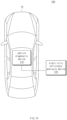
- FIG. 1A is a schematic diagram illustrating the configuration of an electricity efficiency analysis system according to various embodiments.
- the electricity efficiency analysis system 100 may include a vehicle diagnostic device 110 and an electricity efficiency analysis device 120.
- the vehicle diagnostic device 110 may be mounted within the vehicle 10 and may acquire information related to the state or operation of the vehicle 10.
- Information related to the state of the vehicle 10 may include diagnostic information about the components (e.g., the battery, sensors, motor, accelerator, and decelerator) of the vehicle 10.
- information related to the operation of the vehicle may include speed, traveled distance, driving time, location, and electricity consumption of the vehicle 10.
- the vehicle diagnostic device 110 may include an on-board diagnostic (OBD) device.
- OBD devices might encompass various devices that output information about the vehicle's condition or driving to the outside (e.g., fuel efficiency analysis device 120), not restricted to OBD-I, OBD 1.5, and OBD-II.
- the electricity efficiency analysis device 120 may analyze factors influencing the electricity efficiency of the vehicle based on various information obtained through the vehicle diagnostic device 110.
- the electricity efficiency analysis device 120 may calculate a standard electricity efficiency contribution, which indicates the extent to which the current electricity efficiency of the vehicle 10 affects the gains or losses (e.g. increase or decrease) within a driving section (or a section where the electrical energy of the vehicle 10 is consumed) compared to the standard electricity efficiency (e.g., certified electricity efficiency).
- the standard electricity efficiency may be measured under specified conditions by the vehicle diagnostic device 110, the electricity efficiency analysis device 120, or a designated certification authority.
- the electricity efficiency analysis device 120 may include a portable communication device such as a smart phone, a computer device, a portable multimedia device, a wearable device, or a server such as a cloud server, and various embodiments are not limited to the examples.
- FIG. 1B is a diagram illustrating the configuration of an electricity efficiency analysis device according to various embodiments.
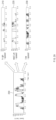
- FIGS. 2A and 2B are diagrams illustrating the calculation operation of a standard electricity efficiency contribution according to various embodiments
- FIGS. 3A and 3B are diagrams illustrating the calculated values of standard electricity efficiency contribution according to various embodiments
- FIGS. 4A to 4D are diagrams illustrating the output operations of standard electricity efficiency contribution according to various embodiments.
- the electricity efficiency analysis device 120 may include communication circuitry 122, a memory 124, an output device 126, and a processor 128.
- this is exemplary, and various embodiments are not limited thereto.
- at least one of the components of the electricity efficiency analysis device 120 may be omitted, or one or more other components (e.g., an input device, at least one sensor, a power management device, etc.) may be added to the configuration of the electricity efficiency analysis device 120.
- at least one of the components may be integrated with other components.
- the communication circuitry 122 may establish a wired or wireless communication channel between the electricity efficiency analysis device 120 and the vehicle diagnostic device 110 and support communication operations through the established communication channels.
- the communication circuitry 122 may also establish communication with other external devices (e.g., servers) aside from the vehicle diagnostic device 110.
- the communication circuitry 122 may include a wireless communication circuit (e.g., a cellular communication circuit or short-range wireless communication circuit) or a wired communication circuit (e.g., a local area network or power line communication circuit).
- a wireless communication circuit e.g., a cellular communication circuit or short-range wireless communication circuit
- a wired communication circuit e.g., a local area network or power line communication circuit
- the memory 124 may contain programs, algorithms, routines, and/or instructions related to the operation (or control) of the electricity efficiency analysis device 120.
- the memory 124 may encompass memory types like flash memory type, hard disk type, micro type, and card type (e.g., secure digital (SD) card or eXtream (XD) digital card), as well as at least one type of storage medium among random access memory (RAM), static RAM (SRAM), read-only memory (ROM), programmable ROM (PROM), electrically erasable PROM (EEPROM), magnetic RAM (MRAM), magnetic disk, and optical disk types, however, various embodiments are not limited to these examples.
- SD secure digital
- XD eXtream
- RAM random access memory
- SRAM static RAM
- ROM read-only memory
- PROM programmable ROM
- EEPROM electrically erasable PROM
- MRAM magnetic RAM
- magnetic disk magnetic disk
- optical disk types optical disk types
- the output device 126 may provide information related to the operation of the electricity efficiency analysis device 120.
- the output device 126 may include a display configured to output visual information.
- the display may include one or more of a liquid crystal display, a thin film transistor-liquid crystal display, an organic light-emitting diode, a flexible display, a 3-dimensional (3D) display, and a transparent display.
- the display 120 may also include a touch sensor configured to detect touches.
- information related to the operation of the electricity efficiency analysis device 120 may be provided in the form of auditory information.
- the output device 126 may further include a sound output device (e.g., speakers) configured to output audio signals from the electricity efficiency analysis device 120 to the outside.
- the processor 128 may control at least one other component of the electricity efficiency analysis device 120 (e.g., communication circuitry 122, memory 124, and output device 126) and perform various data processing or computations.
- the electricity efficiency analysis device 120 e.g., communication circuitry 122, memory 124, and output device 1266 and perform various data processing or computations.
- the processor 128 may provide electricity efficiency (or driving electricity efficiency) for the vehicle 10 based on various information obtained through the vehicle diagnostic device 110. Electricity efficiency may be calculated as the distance that can be traveled per 1 kWh of electrical energy.
- the processor 128 may obtain information about the driving distance and the consumption of electrical energy in a certain section through the vehicle diagnostic device 110. In relation to this, the processor 128 may calculate electricity efficiency by using the ratio of electrical energy consumption to the distance traveled.
- the processor 128 may analyze factors influencing the electricity efficiency of the vehicle 10 based on various information obtained through the vehicle diagnostic device 110, as described below. For example, the processor 128 may calculate the standard electricity efficiency contribution, indicating the extent to which the current electricity efficiency of the vehicle 10, compared to the standard electricity efficiency (e.g., certified electricity efficiency), affects the gains or losses (e.g., increase or decrease).
- the standard electricity efficiency contribution indicating the extent to which the current electricity efficiency of the vehicle 10, compared to the standard electricity efficiency (e.g., certified electricity efficiency)
- the gains or losses e.g., increase or decrease.
- the processor 128 may divide (or split) the section in which the electric energy of the vehicle 10 is consumed into a plurality of sections and calculate the standard electricity efficiency contribution for each section.
- the processor 128 may divide the monitoring section in which the electric energy consumed by the vehicle 10 in driving is monitored into multiple sections and calculate the standard electricity efficiency contribution for each section. In this case, the processor 128 may divide the monitoring section into a plurality of speed sections.
- the processor 128 may divide the monitoring section 200, based on the speed of the vehicle 10, into a first section 210 corresponding to the first speed range (e.g., 81 km/h or above), a second section 220 corresponding to the second speed range (e.g., 31 km/h to 80 km/h), and a third section 230 corresponding to the third speed range (e.g., 1 km/h to 30 km/h).
- first speed range e.g., 81 km/h or above
- second section 220 corresponding to the second speed range
- the third section 230 corresponding to the third speed range
- the processor 128 may calculate the first standard electricity efficiency contribution, the second standard electricity efficiency contribution, and the third standard electricity efficiency contribution for each of the first section 210, second section 220, and third section 230, respectively.
- the processor 128 may use Equation 1 below to calculate the standard electricity efficiency contribution.
- Standard electricity efficiency contribution power consumption rate * Electricity efficiency gain-loss value
- the power consumption rate ( E i E T ) may represent the proportion of power (E i ) consumed in the corresponding section relative to the total power consumption (E T ), and the electricity efficiency gain-loss value ( M i E i ⁇ M S E T ) may represent the gains or losses of the current electricity efficiency ( M i E i ) compared to the standard electricity efficiency ( M S E T ) of the vehicle that is calculated based on the standard electricity efficiency ( M S E T ) of the vehicle and the power (E i ) consumed in the corresponding section to the driving distance (M i ).
- M S may represent the total achievable driving distance based on the standard electricity efficiency.
- the electricity efficiency gain or loss value may be expressed as either a positive or negative value.
- sections with positive values indicate sections where the electricity efficiency is higher than the standard electricity efficiency, while sections with negative values indicate sections where the electricity efficiency is lower than the standard electricity efficiency.
- Equation 1 may be explained through FIGS. 3A and 3B and Equations 2 and 3 below.
- the difference (4) between the standard electricity efficiency of the vehicle 340) and the current electricity efficiency of the vehicle 350 may be expressed as the sum of the first standard electricity efficiency contribution (1) for the first section 310, the second standard electricity efficiency contribution (2) for the second section 320, and the third standard electricity efficiency contribution (3) for the third section 330.
- the standard electricity efficiency contribution may be derived using Equation 3.
- Examples of standard electricity efficiency contribution calculated based on Equation 1 may be summarized as in Table 1 below.
- Table 1 First section Second section Third section Driving distance 6 km 12 km 8 km Section consumption energy 3 kwh 3 kwh 4 kwh Standard electricity efficiency 3 km/kwh Electricity efficiency (section electricity efficiency) 2 km/kwh 4 km/kwh 2 km/kwh Entire section electricity efficiency 2.6 km/kwh Power consumption rate 0.3 0.3 0.4 Electricity efficiency gain-loss value -1 +1 -1 Standard electricity efficiency contribution -0.3 +0.3 -0.4
- the efficiency of the first section e.g., 2 km/kWh
- the efficiency of the third section e.g., 2 km/kWh
- the standard electricity efficiency contribution of the first section e.g., -0.3
- the standard electricity efficiency of the third section e.g., -0.4
- the processor 128 may accurately analyze the factors influencing the efficiency through the standard electricity efficiency contribution and provide them to the driver.
- the electricity efficiency analysis device 120 may calculate the power consumption rate and the electricity efficiency gain-loss value based on various information obtained through the vehicle diagnostic device 110. However, this is exemplary, and various embodiments are not limited thereto. For example, at least some of the power consumption rate and the electricity efficiency gain-loss value may be calculated by the vehicle diagnostic device 110 or other external devices and provided to the electricity efficiency analysis device 120.
- the processor 128 may divide the monitoring section into a plurality of speed sections and further subdivide each speed section into a plurality of sections to calculate the standard efficiency contribution. In this case, the processor 128 may further divide each speed section into a plurality of speed variation sections.
- the speed variation section may encompass at least one of an acceleration section (e.g., a section with acceleration less than 10 km/h per second), a rapid acceleration section (e.g., a section with acceleration greater than or equal to 10 km/h per second), a deceleration section (e.g., a section with deceleration less than 10 km/h per second), a rapid deceleration section (e.g., a section with deceleration greater than or equal to 10 km/h per second), or a constant speed section (e.g., a section with an average acceleration less than 0.2).
- an acceleration section e.g., a section with acceleration less than 10 km/h per second
- a rapid acceleration section e.g., a section with acceleration greater than or equal to 10 km/h per second
- a deceleration section e.g., a section with deceleration less than 10 km/h per second
- a rapid deceleration section e.g., a section with de
- the processor 128 may divide the first section 210 of the monitoring section 200 into speed variation sections such as a constant speed section 212, a rapid acceleration section 214, and a rapid deceleration section 216, and similarly, the second section 220 of the monitoring section 200 into speed variation sections such as an acceleration section 222 and a deceleration section 224.
- the processor 128 may differentiate only certain sections satisfying a predetermined condition among the constant speed section 212, rapid acceleration section 214, and rapid deceleration section 216 of the first section 210 of the monitoring section 200 as speed variation sections.
- the processor 128 may also differentiate only certain sections satisfying a predetermined condition among the plurality of speed sections within the monitoring section 200 as speed variation sections.
- the processor 128 may calculate the standard electricity efficiency contribution for each speed section.
- the standard electricity efficiency contribution may be calculated based on the section (e.g., monitoring section) in which electric energy is consumed by the vehicle 10 in driving.
- the processor 128 may also calculate the standard electricity efficiency contribution based on the section where energy is consumed even when actual driving does not occur (e.g., stopped state).
- the processor 128 may calculate the power consumption rate based on the power consumed in a stopped state. For example, the processor 128 may calculate the standard electricity efficiency contribution for the stopped state based on the power consumption rate calculated based on the power consumed by the air conditioning device (e.g., a cooling device or a heating device) and the electricity efficiency gain-loss value calculated for the stopped state (e.g., with a driving distance of 0 km).
- the air conditioning device e.g., a cooling device or a heating device
- the electricity efficiency gain-loss value calculated for the stopped state e.g., with a driving distance of 0 km.
- the processor 128 may output information related to the calculated standard electricity efficiency contribution (or electricity efficiency contribution information).
- the processor 128 may output electricity efficiency contribution information 400 including first electricity efficiency contribution information 410 related to recent electricity efficiency (or recent driving) and second electricity efficiency contribution information 420 related to electricity efficiency history (or past driving history).
- the processor 128 may selectively output the first electricity efficiency contribution information 410 or the second electricity efficiency contribution information 420 based on user input.
- the processor 128 may also output both the first electricity efficiency contribution information 410 and the second electricity efficiency contribution information 420 based on or regardless of user input.
- the first electricity efficiency contribution information 410 may include the recent driving-based average electricity efficiency 411 (e.g., recent average electricity efficiency: 7.4 km/kWh) and the individually monitored speed section-specific standard electricity efficiency contributions 412 for in recent driving.
- the first electricity efficiency contribution information 410 may include a graph 414 representing the standard contribution efficiencies for individual speed sections monitored. This allows the driver to perceive the speed sections contributing to electricity efficiency improvement or reduction, ultimately inducing driver habits for better efficiency.
- the processor 128 may provide detailed standard efficiency contribution information for at least one speed section based on user input.
- the processor 128, as shown in FIG. 4B may provide speed variation section-specific standard efficiency contribution 416 for the selected speed section (e.g., rapid acceleration section, acceleration section, gentle acceleration section, rapid deceleration section, deceleration section, gentle deceleration section, or constant speed section).
- speed section e.g., rapid acceleration section, acceleration section, gentle acceleration section, rapid deceleration section, deceleration section, gentle deceleration section, or constant speed section.
- the processor 128 may, when outputting the electricity efficiency contribution information, also provide information related to gain and loss incurred based on the standard electricity efficiency contribution.
- the processor 128 may calculate gain and loss by multiplying the standard electricity efficiency contribution with unit energy cost (e.g., cost per kWh).
- the processor 128 may also provide information about the proportion of sections with high or low standard electricity efficiency contributions in the overall driving range.
- the processor 128 may provide a comparison result between the standard electricity efficiency contribution based on past driving and the standard electricity efficiency contribution based on current driving through the second electricity efficiency contribution information 420 related to the electricity efficiency history.
- the processor 128 may select one of the stored standard electricity efficiency contributions for a plurality of past drives and compare it with the standard electricity efficiency contribution for the current drive. For example, at least one of the past drives with optimal electricity efficiency, past drive immediately before the current drive, past drive on a similar route to the current drive, and past drive performed a lot over a period may be selected as a comparison target to be compared with the current drive.
- the processor 128 may output the second electricity efficiency contribution information 420 including a graph 422 comparing the decrease or increase in efficiency in the current drive compared to past drives and textual information 424 regarding the comparison result.
- the second electricity efficiency contribution information 420 may include an object (e.g., a detailed information check icon 426) that triggers the output of detailed information about the sections where efficiency decreased or increased in the current drive compared to past drives.
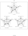
- the processor 128 may provide detailed information 428 about the sections of the current drive where the electricity efficiency has decreased or increased compared to the past drive or about the speed variation sections (or actions) that have decreased or increased the electricity efficiency in those sections, as shown in FIG. 4D .
- FIG. 4D the detailed comparison results between the electricity efficiency of past drives and the current drive were provided as detailed information 428 through a radial graph, various embodiments are not limited to this example.
- FIG. 5 is a flowchart illustrating the operation of an electricity efficiency analysis device according to various embodiments.
- the operations may be performed in sequence, but they do not have to be carried out in a strict sequential order.
- the order of the operations may be changed, and at least two operations may be performed in parallel.
- at least one of the operations may be omitted depending on the embodiment.
- the electricity efficiency analysis device 120 may monitor the energy consumption of the vehicle at operation 510.
- the electricity efficiency analysis device 120 may monitor the energy consumption of the vehicle based on information acquired through the vehicle diagnostic device 110. For example, the electricity efficiency analysis device 120 may perform monitoring during a section (e.g., a driving section) where electrical energy is consumed by driving. In another example, the electricity efficiency analysis device 120 may also perform monitoring even in a state where driving is not actually performed (e.g., a stopped section).
- the electricity efficiency analysis device 120 may divide (or split) the monitoring section into a plurality of sections at operation 520.
- the electricity efficiency analysis device 120 may divide the monitoring section into a plurality of speed sections.
- the plurality of speed sections may include the first section (e.g., high-speed section) corresponding to the first speed range (e.g., 81 km/h and above), the second section (e.g., medium-speed section) corresponding to the second speed range (e.g., 31 km/h to 80 km/h), and the third section (e.g., low-speed section) corresponding to the third speed range (e.g., 1 km/h to 30 km/h).
- the electricity efficiency analysis device 120 may calculate the power consumption rate and the electricity efficiency gain-loss value for each segment at operation 530.
- the power consumption rate may be a numerical representation of the proportion of power consumed in each segment to the total power consumption within the monitoring section
- the electricity efficiency gain-loss value may be the numerical representation of the electricity efficiency gain or loss compared to the standard electricity efficiency (e.g., certified efficiency) of the vehicle.
- the power efficiency analysis device 120 may calculate the standard electricity efficiency contribution based on the power consumption rate and the electricity efficiency gain/loss value at operation 540.
- the standard electricity efficiency contribution may represent the extent to which the current electricity efficiency of the vehicle 10 affects the gain or loss (e.g., increase or decrease) compared to the standard electricity efficiency (e.g., certified efficiency).
- the electricity efficiency analysis device 120 may use Equation 1 to calculate the standard electricity efficiency contribution.
- the electricity efficiency analysis device 120 may output information related to the calculated standard electricity efficiency contribution at operation 550.
- the electricity efficiency analysis device 120 may output electricity efficiency contribution information including the first electricity efficiency contribution information (e.g., the first electricity efficiency contribution information 410 of FIG. 4A ) related to recent efficiency and the second electricity efficiency contribution information (e.g., the second electricity efficiency contribution information 420 of FIG. 4A ) related to electricity efficiency history.
- first electricity efficiency contribution information e.g., the first electricity efficiency contribution information 410 of FIG. 4A
- second electricity efficiency contribution information e.g., the second electricity efficiency contribution information 420 of FIG. 4A
- the electricity efficiency analysis device 120 may also provide information related to gain-loss costs resulting from the standard electricity efficiency contribution.
- the electricity efficiency analysis device 120 may calculate gain-loss costs by multiplying the standard electricity efficiency contribution with unit energy cost (e.g., cost per kWh).
- the electricity efficiency analysis device 120 may also provide information about the proportion of sections with high standard electricity efficiency contributions or low standard electricity efficiency section within the entire driving section.
- FIG. 6 is a flowchart illustrating the operation of calculating power consumption rate and electricity efficiency gain/loss values in an electricity efficiency analysis device according to various embodiments.
- the operations described below in FIG. 6 may be various embodiments of operations 520 and 530 in FIG. 5 .
- the operations may be performed in sequence, but they do not have to be carried out in a strict sequential order.
- the order of the operations may be changed, and at least two operations may be performed in parallel.
- at least one of the operations may be omitted depending on the embodiment.
- the electricity efficiency analysis device 120 may differentiate a plurality of speed sections at operation 610. This corresponds to operation 520 in FIG. 5 .
- the electricity efficiency analysis device 120 may divide each segmented speed section into a plurality of speed variation sections at operation 620.
- the electricity efficiency analysis device 120 may divide each speed section into a plurality of speed variation sections based on the acceleration of the vehicle 10.
- the plurality of speed variation sections may include at least one of a rapid acceleration section, an acceleration section, a gentle acceleration section, a rapid deceleration section, a deceleration section, a gentle deceleration section, or a constant speed section.
- the electricity efficiency analysis device 120 may also differentiate only certain speed variation sections satisfying a predetermined condition among the plurality of speed variation sections included in each speed section.
- the electricity efficiency analysis device 120 may calculate the power consumption rate and electricity efficiency gain-loss value for each of the speed variation sections at operation 630. Afterward, the electricity efficiency analysis device 120 may calculate the standard electricity efficiency contribution for each of the speed variation sections.
Landscapes
- Engineering & Computer Science (AREA)
- Power Engineering (AREA)
- General Physics & Mathematics (AREA)
- Physics & Mathematics (AREA)
- Mechanical Engineering (AREA)
- Transportation (AREA)
- Sustainable Development (AREA)
- Sustainable Energy (AREA)
- Life Sciences & Earth Sciences (AREA)
- Chemical & Material Sciences (AREA)
- Combustion & Propulsion (AREA)
- Electric Propulsion And Braking For Vehicles (AREA)
- Combined Controls Of Internal Combustion Engines (AREA)
Abstract
Description
- The embodiments disclosed in this document claim the benefit of priority based on
Korean Patent Application Nos. 10-2022-0101645 filed on August 12, 2022 10-2023-0105701 filed on August 11, 2023 - The various embodiments disclosed in this document relate to an electricity efficiency analysis device, system including the same, and operating method thereof, and more particularly, to a technology for analyzing factors influencing the electricity efficiency of a vehicle.
- Due to growing environmental concerns, there is an increase in the adoption of eco-friendly vehicles, such as electric cars and fuel cell vehicles. These eco-friendly vehicles are equipped with batteries and run on the battery's electric energy.
- The vehicle provides a function to calculate and display the vehicle's electricity efficiency (or driving electricity efficiency) through instruments such as the cluster. Electricity efficiency can be calculated as the distance that can be traveled per 1 kWh of electrical energy.
- Typically, electricity efficiency can be derived based on the consumption of electrical energy and the distance traveled over a specific distance section. For example, electricity efficiency can be calculated as the ratio of electrical energy consumption to the distance traveled.
- The provision of this electricity efficiency can help drivers plan their charging during or before driving. However, even among vehicles of the same type, electricity efficiency can vary depending on road conditions, driver's driving habits, and vehicle condition, and drivers cannot discern from the provided electricity efficiency alone which factors affect the electricity efficiency.
- At least one of the various embodiments of the present invention aims to provide an electricity analysis device, a system including the same, and operating method thereof designed to analyze factors influencing the electricity efficiency of a vehicle.
- At least one of the various embodiments of the present invention aims to provide an electricity efficiency analysis device, system including the same, and opera ting method thereof designed to analyze the reasons for an increase or decrease in the current electricity efficiency of a vehicle compared to the standard electricity efficiency.
- An electricity efficiency analysis device according to various embodiments includes an output device and a processor electrically connected to the output device, the processor configured to calculate an electricity efficiency gain-loss value indicating a gain or loss of current electricity efficiency compared to a standard electricity efficiency of a vehicle based on the information collected during a predetermined monitoring section related to the state and driving of the vehicle, calculate a standard electricity efficiency contribution indicating an extent to which the state and driving of the vehicle during the predetermined monitoring section have influenced the gain or loss of the current electricity efficiency compared to the standard electricity efficiency based on a power consumption rate and the electricity efficiency gain-loss value during the predetermined monitoring section, and output the standard electricity efficiency contribution through the output device.
- According to various embodiments, the processor may be configured to calculate the power consumption rate as a ratio of power consumed during the predetermined monitoring section to a total power consumption.
- According to various embodiments, the processor may be configured to calculate the standard electricity efficiency contribution using a product of the power consumption rate and the electricity efficiency gain-loss value.
- According to various embodiments, the processor may be configured to divide the predetermined monitoring section into a plurality of speed sections satisfying predetermined speed conditions based on the information and calculate speed section-specific standard electricity efficiency contributions.
- According to various embodiments, the processor may be configured to divide each speed section into a plurality of speed variation sections satisfying predetermined speed variation conditions and calculate speed variation section-specific standard electricity efficiency contributions.
- According to various embodiments, the processor may be configured to output at least one of a first standard electricity efficiency contribution related to a recent driving of the vehicle or a second standard electricity efficiency contribution related to a past driving history of the vehicle.
- According to various embodiments, the processor may be configured to calculate a gain-loss cost incurred based on the standard electricity efficiency contribution and output information on the gain-loss cost through the output device.
- According to various embodiments, the electricity efficiency analysis device may further include a communication circuitry configured to establishing communication with a vehicle diagnostic device, wherein the processor may be configured to acquire the information related to the state and driving of the vehicle through the vehicle diagnostic device.
- An electricity efficiency analysis system according to various embodiments includes a vehicle diagnostic device configured to acquire information related to state and driving of a vehicle and an electricity efficiency analysis device capable of communicating with the vehicle antagonistic device, the electricity efficiency analysis device configured to acquire an electricity efficiency gain-loss value indicating a gain or loss of current electricity efficiency of the vehicle compared to a standard electricity efficiency of the vehicle and a power consumption rate of the vehicle during a predetermined monitoring section based on the information acquired by the vehicle diagnostic device, and calculate a standard electricity efficiency contribution indicating an extent to which the state and driving of the vehicle during the predetermined monitoring section have influenced the gain or loss of the current electricity efficiency compared to the standard electricity efficiency, based on the acquired electricity efficiency gain-loss value and power consumption rate.
- According to various embodiments, the electricity efficiency analysis device may be configured to acquire the electricity efficiency gain-loss value and the power consumption rate calculated by the vehicle diagnostic device.
- According to various embodiments, the electricity efficiency analysis device may be configured to calculate the electricity efficiency gain-loss value and the power consumption rate based on the Information acquired through the vehicle diagnostic device.
- According to various embodiments, the electricity efficiency analysis device may be configured to calculate the standard electricity efficiency contribution using a product of the power consumption rate and the electricity efficiency gain-loss value.
- An operating method of an electricity efficiency analysis device according to various embodiments may include calculating an electricity efficiency gain-loss value indicating a gain or loss of current electricity efficiency compared to a standard electricity efficiency of a vehicle based on information collected during a predetermined monitoring section related to state and driving of the vehicle, calculating a standard electricity efficiency contribution indicating an extent to which the state and driving of the vehicle during the predetermined monitoring section have influenced the gain or loss of the current electricity efficiency compared to the standard electricity efficiency based on a power consumption rate and the electricity efficiency gain-loss value during the predetermined monitoring section, and outputting the standard electricity efficiency contribution through an output device.
- According to various embodiments, the power consumption rate may be calculated as a ratio of power consumed during the predetermined monitoring section to a total power consumption.
- According to various embodiments, the standard electricity efficiency contribution may be calculated using a product of the power consumption rate and the electricity efficiency gain-loss value.
- According to various embodiments, outputting the standard electricity efficiency contribution may include dividing the predetermined monitoring section into a plurality of speed sections satisfying predetermined speed conditions based on the information and calculating speed section-specific standard electricity efficiency contributions.
- According to various embodiments, outputting the standard electricity efficiency contribution may include dividing each speed section into a plurality of speed variation sections satisfying predetermined speed variation conditions and calculating speed variation section-specific standard electricity efficiency contributions.
- According to various embodiments, outputting the standard electricity efficiency contribution may include outputting at least one of a first standard electricity efficiency contribution related to a recent driving of the vehicle or a second standard electricity efficiency contribution related to a past driving history of the vehicle.
- According to various embodiments, outputting the standard electricity efficiency contribution may include calculating a gain-loss cost incurred based on the standard electricity efficiency contribution and outputting information on the gain-loss cost through the output device.
- The operating method of the electricity efficiency analysis device according to various embodiments may further include establishing communication with a vehicle diagnostic device and acquiring the information related to the state and driving of the vehicle through the vehicle diagnostic device.
- The electricity efficiency analysis device according to various embodiments disclosed in this document can analyze factors influencing the electricity efficiency of a vehicle, enabling drivers to become aware of the factors contributing to forming electricity efficiency.
- The electricity efficiency analysis device according to various embodiments disclosed in this document can induce efficient driving habits for improving electricity efficiency by analyzing the extent to which the current electricity efficiency of a vehicle, compared to the standard electricity efficiency, affects the gains or losses (e.g., increase or decrease).
- The effects achievable from this document are not limited to those mentioned above.
-
-
FIG. 1A is a schematic diagram illustrating the configuration of an electricity efficiency analysis system according to various embodiments; -
FIG. 1B is a diagram illustrating the configuration of an electricity efficiency analysis device according to various embodiments; -
FIGS. 2A and2B are diagrams illustrating the calculation operation of a standard electricity efficiency contribution according to various embodiments; -
FIGS. 3A and3B are diagrams illustrating the calculated values of standard electricity efficiency contribution according to various embodiments; -
FIGS. 4A to 4D are diagrams illustrating the output operations of standard electricity efficiency contribution according to various embodiments; -
FIG. 5 is a flowchart illustrating the operation of an electricity efficiency analysis device according to various embodiments; and -
FIG. 6 is a flowchart illustrating the operation of calculating power consumption rate and electricity efficiency gain/loss values in an electricity efficiency analysis device according to various embodiments. - Hereinafter, some embodiments of the present invention are described in detail with reference to accompanying drawings. It should be noted that the same numerals are assigned to identical components, even though they are shown on different drawings. In addition, in the following description of the embodiments of the present invention, detailed descriptions of well-known components and functions may be omitted if they are deemed to obstruct the understanding of the embodiments of the present invention.
- In describing the components of the embodiments of the present invention, terms such as "first," "second," "A," "B," "(a)," "(b)," etc., may be used. These terms are only used only to distinguish one component from another component, and the nature, sequence, or order of the corresponding components are not limited by the term. Furthermore, unless otherwise defined differently, all terms used herein, including technical or scientific terminology, have the same meanings as understood by those skilled in the art in the relevant field of the invention. It will be further understood that terms, such as those defined in commonly used dictionaries, should be interpreted as having a meaning that is consistent with their meaning in the context of the relevant art and should not be interpreted in an idealized or overly formal sense unless expressly so defined herein.
- The vehicle referred to in the following description may include a vehicle that is operated under the control of a boarded driver and a self-driving vehicle that can operate on its own without the driver's manipulation. In addition, the following description describes a car as an example of a vehicle, but the invention is not limited thereto. For example, the following embodiments can be applied to various means of transportation, such as ships, aircraft, trains, motorcycles, or bicycles.
- Hereinafter, the embodiments of the present invention are described in detail with reference to
FIGS. 1A to 6 . -
FIG. 1A is a schematic diagram illustrating the configuration of an electricity efficiency analysis system according to various embodiments. - With reference to
FIG. 1A , the electricityefficiency analysis system 100 according to various embodiments may include a vehiclediagnostic device 110 and an electricityefficiency analysis device 120. - According to various embodiments, the vehicle
diagnostic device 110 may be mounted within thevehicle 10 and may acquire information related to the state or operation of thevehicle 10. Information related to the state of thevehicle 10 may include diagnostic information about the components (e.g., the battery, sensors, motor, accelerator, and decelerator) of thevehicle 10. In addition, information related to the operation of the vehicle may include speed, traveled distance, driving time, location, and electricity consumption of thevehicle 10. In an embodiment, the vehiclediagnostic device 110 may include an on-board diagnostic (OBD) device. Such OBD devices might encompass various devices that output information about the vehicle's condition or driving to the outside (e.g., fuel efficiency analysis device 120), not restricted to OBD-I, OBD 1.5, and OBD-II. - According to various embodiments, the electricity
efficiency analysis device 120 may analyze factors influencing the electricity efficiency of the vehicle based on various information obtained through the vehiclediagnostic device 110. The electricityefficiency analysis device 120 may calculate a standard electricity efficiency contribution, which indicates the extent to which the current electricity efficiency of thevehicle 10 affects the gains or losses (e.g. increase or decrease) within a driving section (or a section where the electrical energy of thevehicle 10 is consumed) compared to the standard electricity efficiency (e.g., certified electricity efficiency). The standard electricity efficiency may be measured under specified conditions by the vehiclediagnostic device 110, the electricityefficiency analysis device 120, or a designated certification authority. For example, the electricityefficiency analysis device 120 may include a portable communication device such as a smart phone, a computer device, a portable multimedia device, a wearable device, or a server such as a cloud server, and various embodiments are not limited to the examples. - Hereinafter, a description is made of the calculation of the standard electricity efficiency contribution by the electricity
efficiency analysis device 120 in detail with reference to accompanying drawings. -
FIG. 1B is a diagram illustrating the configuration of an electricity efficiency analysis device according to various embodiments. AndFIGS. 2A and2B are diagrams illustrating the calculation operation of a standard electricity efficiency contribution according to various embodiments,FIGS. 3A and3B are diagrams illustrating the calculated values of standard electricity efficiency contribution according to various embodiments, and lastly,FIGS. 4A to 4D are diagrams illustrating the output operations of standard electricity efficiency contribution according to various embodiments. - With reference to
FIG. 1B , the electricityefficiency analysis device 120 may includecommunication circuitry 122, amemory 124, anoutput device 126, and aprocessor 128. However, this is exemplary, and various embodiments are not limited thereto. For example, at least one of the components of the electricityefficiency analysis device 120 may be omitted, or one or more other components (e.g., an input device, at least one sensor, a power management device, etc.) may be added to the configuration of the electricityefficiency analysis device 120. In addition, at least one of the components may be integrated with other components. - According to various embodiments, the
communication circuitry 122 may establish a wired or wireless communication channel between the electricityefficiency analysis device 120 and the vehiclediagnostic device 110 and support communication operations through the established communication channels. In addition, thecommunication circuitry 122 may also establish communication with other external devices (e.g., servers) aside from the vehiclediagnostic device 110. - For example, the
communication circuitry 122 may include a wireless communication circuit (e.g., a cellular communication circuit or short-range wireless communication circuit) or a wired communication circuit (e.g., a local area network or power line communication circuit). - According to various embodiments, the
memory 124 may contain programs, algorithms, routines, and/or instructions related to the operation (or control) of the electricityefficiency analysis device 120. - For example, the
memory 124 may encompass memory types like flash memory type, hard disk type, micro type, and card type (e.g., secure digital (SD) card or eXtream (XD) digital card), as well as at least one type of storage medium among random access memory (RAM), static RAM (SRAM), read-only memory (ROM), programmable ROM (PROM), electrically erasable PROM (EEPROM), magnetic RAM (MRAM), magnetic disk, and optical disk types, however, various embodiments are not limited to these examples. - According to various embodiments, the
output device 126 may provide information related to the operation of the electricityefficiency analysis device 120. In an embodiment, theoutput device 126 may include a display configured to output visual information. For example, the display may include one or more of a liquid crystal display, a thin film transistor-liquid crystal display, an organic light-emitting diode, a flexible display, a 3-dimensional (3D) display, and a transparent display. Thedisplay 120 may also include a touch sensor configured to detect touches. - However, this is exemplary, and various embodiments are not limited thereto. For example, information related to the operation of the electricity
efficiency analysis device 120 may be provided in the form of auditory information. In this case, theoutput device 126 may further include a sound output device (e.g., speakers) configured to output audio signals from the electricityefficiency analysis device 120 to the outside. - According to various embodiments, the
processor 128 may control at least one other component of the electricity efficiency analysis device 120 (e.g.,communication circuitry 122,memory 124, and output device 126) and perform various data processing or computations. - According to an embodiment, the
processor 128 may provide electricity efficiency (or driving electricity efficiency) for thevehicle 10 based on various information obtained through the vehiclediagnostic device 110. Electricity efficiency may be calculated as the distance that can be traveled per 1 kWh of electrical energy. - For example, the
processor 128 may obtain information about the driving distance and the consumption of electrical energy in a certain section through the vehiclediagnostic device 110. In relation to this, theprocessor 128 may calculate electricity efficiency by using the ratio of electrical energy consumption to the distance traveled. - The provision of this electricity efficiency can help drivers plan their charging during or before driving. However, even among vehicles of the same type, electricity efficiency can vary depending on road conditions, driver's driving habits, and vehicle condition, and drivers cannot discern from the provided electricity efficiency alone which factors affect the electricity efficiency.
- In this regard, the
processor 128 may analyze factors influencing the electricity efficiency of thevehicle 10 based on various information obtained through the vehiclediagnostic device 110, as described below. For example, theprocessor 128 may calculate the standard electricity efficiency contribution, indicating the extent to which the current electricity efficiency of thevehicle 10, compared to the standard electricity efficiency (e.g., certified electricity efficiency), affects the gains or losses (e.g., increase or decrease). - According to an embodiment, the
processor 128 may divide (or split) the section in which the electric energy of thevehicle 10 is consumed into a plurality of sections and calculate the standard electricity efficiency contribution for each section. - According to an embodiment, the
processor 128 may divide the monitoring section in which the electric energy consumed by thevehicle 10 in driving is monitored into multiple sections and calculate the standard electricity efficiency contribution for each section. In this case, theprocessor 128 may divide the monitoring section into a plurality of speed sections. - For example, as shown in
FIG. 2A , theprocessor 128 may divide themonitoring section 200, based on the speed of thevehicle 10, into afirst section 210 corresponding to the first speed range (e.g., 81 km/h or above), asecond section 220 corresponding to the second speed range (e.g., 31 km/h to 80 km/h), and athird section 230 corresponding to the third speed range (e.g., 1 km/h to 30 km/h). - Subsequently, the
processor 128 may calculate the first standard electricity efficiency contribution, the second standard electricity efficiency contribution, and the third standard electricity efficiency contribution for each of thefirst section 210,second section 220, andthird section 230, respectively. - According to an embodiment, the
processor 128 may useEquation 1 below to calculate the standard electricity efficiency contribution.Standard electricity efficiency contribution = power consumption rate * Electricity efficiency gain-loss value - Power consumption rate =


- In
Equation 1, the power consumption rate (


-
Equation 1 may be explained throughFIGS. 3A and3B andEquations - As shown in
FIGS. 3A and3B , within theoverall monitoring section 300 encompassing thefirst section 310,second section 320, andthird section 330, the difference (④) between the standard electricity efficiency of the vehicle 340) and the current electricity efficiency of thevehicle 350 may be expressed as the sum of the first standard electricity efficiency contribution (①) for thefirst section 310, the second standard electricity efficiency contribution (②) for thesecond section 320, and the third standard electricity efficiency contribution (③) for thethird section 330. - This difference in electricity efficiency (④) may be derived using
Equation 2.
- Based on
Equation 2 above, the standard electricity efficiency contribution may be derived usingEquation 3.
- According to an embodiment, examples of standard electricity efficiency contribution calculated based on
Equation 1 may be summarized as in Table 1 below.Table 1 First section Second section Third section Driving distance 6 km 12 km 8 km Section consumption energy 3 kwh 3 kwh 4 kwh Standard electricity efficiency 3 km/kwh Electricity efficiency (section electricity efficiency) 2 km/ kwh 4 km/ kwh 2 km/kwh Entire section electricity efficiency 2.6 km/kwh Power consumption rate 0.3 0.3 0.4 Electricity efficiency gain-loss value -1 +1 -1 Standard electricity efficiency contribution -0.3 +0.3 -0.4 - Referring to Table 1, it is observed that the sum of the standard electricity efficiency and the standard electricity efficiency contributions of individual sections (e.g., 3 - 0.3 + 0.3 - 0.4 = 2.6) is equal to the efficiency (e.g., 26 km/10 kWh = 2.6) of the entire section (e.g., from
section 1 to section 3). Furthermore, it is observed that the efficiency of the first section (e.g., 2 km/kWh) and the efficiency of the third section (e.g., 2 km/kWh) are the same, but the standard electricity efficiency contribution of the first section (e.g., -0.3) and the standard electricity efficiency of the third section (e.g., -0.4) are different from each other. This means that the standard electricity efficiency contribution in the same electricity efficiency section may vary depending on the driver's driving behavior. In this regard, theprocessor 128 may accurately analyze the factors influencing the efficiency through the standard electricity efficiency contribution and provide them to the driver. As described above, the electricityefficiency analysis device 120 may calculate the power consumption rate and the electricity efficiency gain-loss value based on various information obtained through the vehiclediagnostic device 110. However, this is exemplary, and various embodiments are not limited thereto. For example, at least some of the power consumption rate and the electricity efficiency gain-loss value may be calculated by the vehiclediagnostic device 110 or other external devices and provided to the electricityefficiency analysis device 120. According to an embodiment, theprocessor 128 may divide the monitoring section into a plurality of speed sections and further subdivide each speed section into a plurality of sections to calculate the standard efficiency contribution. In this case, theprocessor 128 may further divide each speed section into a plurality of speed variation sections. The speed variation section may encompass at least one of an acceleration section (e.g., a section with acceleration less than 10 km/h per second), a rapid acceleration section (e.g., a section with acceleration greater than or equal to 10 km/h per second), a deceleration section (e.g., a section with deceleration less than 10 km/h per second), a rapid deceleration section (e.g., a section with deceleration greater than or equal to 10 km/h per second), or a constant speed section (e.g., a section with an average acceleration less than 0.2). - For example, as shown in
FIG. 2B , theprocessor 128 may divide thefirst section 210 of themonitoring section 200 into speed variation sections such as aconstant speed section 212, arapid acceleration section 214, and arapid deceleration section 216, and similarly, thesecond section 220 of themonitoring section 200 into speed variation sections such as anacceleration section 222 and adeceleration section 224. In addition, theprocessor 128 may differentiate only certain sections satisfying a predetermined condition among theconstant speed section 212,rapid acceleration section 214, andrapid deceleration section 216 of thefirst section 210 of themonitoring section 200 as speed variation sections. Of course, theprocessor 128 may also differentiate only certain sections satisfying a predetermined condition among the plurality of speed sections within themonitoring section 200 as speed variation sections. - Afterward, the
processor 128 may calculate the standard electricity efficiency contribution for each speed section. - As described above, the standard electricity efficiency contribution may be calculated based on the section (e.g., monitoring section) in which electric energy is consumed by the
vehicle 10 in driving. However, this is exemplary, and various embodiments are not limited thereto. For example, additionally or alternatively, theprocessor 128 may also calculate the standard electricity efficiency contribution based on the section where energy is consumed even when actual driving does not occur (e.g., stopped state). - According to an embodiment, the
processor 128 may calculate the power consumption rate based on the power consumed in a stopped state. For example, theprocessor 128 may calculate the standard electricity efficiency contribution for the stopped state based on the power consumption rate calculated based on the power consumed by the air conditioning device (e.g., a cooling device or a heating device) and the electricity efficiency gain-loss value calculated for the stopped state (e.g., with a driving distance of 0 km). - According to various embodiments, the
processor 128 may output information related to the calculated standard electricity efficiency contribution (or electricity efficiency contribution information). - According to an embodiment, as shown in
FIG. 4A , theprocessor 128 may output electricityefficiency contribution information 400 including first electricityefficiency contribution information 410 related to recent electricity efficiency (or recent driving) and second electricityefficiency contribution information 420 related to electricity efficiency history (or past driving history). In this case, theprocessor 128 may selectively output the first electricityefficiency contribution information 410 or the second electricityefficiency contribution information 420 based on user input. Of course, theprocessor 128 may also output both the first electricityefficiency contribution information 410 and the second electricityefficiency contribution information 420 based on or regardless of user input. - According to an embodiment, the first electricity
efficiency contribution information 410 may include the recent driving-based average electricity efficiency 411 (e.g., recent average electricity efficiency: 7.4 km/kWh) and the individually monitored speed section-specific standardelectricity efficiency contributions 412 for in recent driving. In addition, the first electricityefficiency contribution information 410 may include agraph 414 representing the standard contribution efficiencies for individual speed sections monitored. This allows the driver to perceive the speed sections contributing to electricity efficiency improvement or reduction, ultimately inducing driver habits for better efficiency. - Furthermore, additionally or alternatively, while the first electricity
efficiency contribution information 410 is being displayed, theprocessor 128 may provide detailed standard efficiency contribution information for at least one speed section based on user input. - For example, when a specific speed section (e.g., low-speed section), is selected through the speed section-specific standard
electricity efficiency contributions 412 or the standard electricityefficiency contribution graph 414, theprocessor 128, as shown inFIG. 4B , may provide speed variation section-specificstandard efficiency contribution 416 for the selected speed section (e.g., rapid acceleration section, acceleration section, gentle acceleration section, rapid deceleration section, deceleration section, gentle deceleration section, or constant speed section). This allows the driver to perceive actions that decrease (e.g., acceleration action) or enhance (e.g., deceleration action) efficiency in the low-speed section. - According to an embodiment, the
processor 128 may, when outputting the electricity efficiency contribution information, also provide information related to gain and loss incurred based on the standard electricity efficiency contribution. In this regard, theprocessor 128 may calculate gain and loss by multiplying the standard electricity efficiency contribution with unit energy cost (e.g., cost per kWh). In addition, when outputting the electricity efficiency contribution information, theprocessor 128 may also provide information about the proportion of sections with high or low standard electricity efficiency contributions in the overall driving range. - According to an embodiment, the
processor 128 may provide a comparison result between the standard electricity efficiency contribution based on past driving and the standard electricity efficiency contribution based on current driving through the second electricityefficiency contribution information 420 related to the electricity efficiency history. In this case, theprocessor 128 may select one of the stored standard electricity efficiency contributions for a plurality of past drives and compare it with the standard electricity efficiency contribution for the current drive. For example, at least one of the past drives with optimal electricity efficiency, past drive immediately before the current drive, past drive on a similar route to the current drive, and past drive performed a lot over a period may be selected as a comparison target to be compared with the current drive. - For example, as shown in
FIG. 4C , theprocessor 128 may output the second electricityefficiency contribution information 420 including agraph 422 comparing the decrease or increase in efficiency in the current drive compared to past drives andtextual information 424 regarding the comparison result. - Additionally or alternatively, the second electricity
efficiency contribution information 420 may include an object (e.g., a detailed information check icon 426) that triggers the output of detailed information about the sections where efficiency decreased or increased in the current drive compared to past drives. When the user's input to the object is detected, theprocessor 128 may providedetailed information 428 about the sections of the current drive where the electricity efficiency has decreased or increased compared to the past drive or about the speed variation sections (or actions) that have decreased or increased the electricity efficiency in those sections, as shown inFIG. 4D . Although the detailed comparison results between the electricity efficiency of past drives and the current drive were provided asdetailed information 428 through a radial graph, various embodiments are not limited to this example. - Hereinafter, a detailed description is made of the operation method of the electricity
efficiency analysis device 120 according to various embodiments with reference toFIGS. 5 and6 . -
FIG. 5 is a flowchart illustrating the operation of an electricity efficiency analysis device according to various embodiments. In the following embodiments, the operations may be performed in sequence, but they do not have to be carried out in a strict sequential order. For example, the order of the operations may be changed, and at least two operations may be performed in parallel. In addition, at least one of the operations may be omitted depending on the embodiment. - With reference to
FIG. 5 , the electricity efficiency analysis device 120 (e.g., processor 128) may monitor the energy consumption of the vehicle atoperation 510. In an embodiment, the electricityefficiency analysis device 120 may monitor the energy consumption of the vehicle based on information acquired through the vehiclediagnostic device 110. For example, the electricityefficiency analysis device 120 may perform monitoring during a section (e.g., a driving section) where electrical energy is consumed by driving. In another example, the electricityefficiency analysis device 120 may also perform monitoring even in a state where driving is not actually performed (e.g., a stopped section). - In various embodiments, the electricity efficiency analysis device 120 (e.g., processor 128) may divide (or split) the monitoring section into a plurality of sections at
operation 520. According to an embodiment, the electricityefficiency analysis device 120 may divide the monitoring section into a plurality of speed sections. The plurality of speed sections may include the first section (e.g., high-speed section) corresponding to the first speed range (e.g., 81 km/h and above), the second section (e.g., medium-speed section) corresponding to the second speed range (e.g., 31 km/h to 80 km/h), and the third section (e.g., low-speed section) corresponding to the third speed range (e.g., 1 km/h to 30 km/h). - According to various embodiments, the electricity efficiency analysis device 120 (e.g., processor 128), may calculate the power consumption rate and the electricity efficiency gain-loss value for each segment at
operation 530. The power consumption rate may be a numerical representation of the proportion of power consumed in each segment to the total power consumption within the monitoring section, and the electricity efficiency gain-loss value may be the numerical representation of the electricity efficiency gain or loss compared to the standard electricity efficiency (e.g., certified efficiency) of the vehicle. - According to various embodiments, the power efficiency analysis device 120 (e.g., processor 128) may calculate the standard electricity efficiency contribution based on the power consumption rate and the electricity efficiency gain/loss value at
operation 540. The standard electricity efficiency contribution may represent the extent to which the current electricity efficiency of thevehicle 10 affects the gain or loss (e.g., increase or decrease) compared to the standard electricity efficiency (e.g., certified efficiency). According to an embodiment, the electricityefficiency analysis device 120 may useEquation 1 to calculate the standard electricity efficiency contribution. - According to various embodiments, the electricity efficiency analysis device 120 (e.g., processor 128) may output information related to the calculated standard electricity efficiency contribution at
operation 550. - According to an embodiment, the electricity
efficiency analysis device 120 may output electricity efficiency contribution information including the first electricity efficiency contribution information (e.g., the first electricityefficiency contribution information 410 ofFIG. 4A ) related to recent efficiency and the second electricity efficiency contribution information (e.g., the second electricityefficiency contribution information 420 ofFIG. 4A ) related to electricity efficiency history. - According to another embodiment, the electricity
efficiency analysis device 120 may also provide information related to gain-loss costs resulting from the standard electricity efficiency contribution. In this regard, the electricityefficiency analysis device 120 may calculate gain-loss costs by multiplying the standard electricity efficiency contribution with unit energy cost (e.g., cost per kWh). - According to another embodiment, the electricity
efficiency analysis device 120 may also provide information about the proportion of sections with high standard electricity efficiency contributions or low standard electricity efficiency section within the entire driving section. -
FIG. 6 is a flowchart illustrating the operation of calculating power consumption rate and electricity efficiency gain/loss values in an electricity efficiency analysis device according to various embodiments. - The operations described below in
FIG. 6 may be various embodiments ofoperations FIG. 5 . In the following embodiments, the operations may be performed in sequence, but they do not have to be carried out in a strict sequential order. For example, the order of the operations may be changed, and at least two operations may be performed in parallel. In addition, at least one of the operations may be omitted depending on the embodiment. - With reference to
FIG. 6 , the electricity efficiency analysis device 120 (or Processor 128) may differentiate a plurality of speed sections atoperation 610. This corresponds tooperation 520 inFIG. 5 . - According to various embodiments, the electricity efficiency analysis device 120 (e.g., Processor 128), may divide each segmented speed section into a plurality of speed variation sections at
operation 620. According to an embodiment, the electricityefficiency analysis device 120 may divide each speed section into a plurality of speed variation sections based on the acceleration of thevehicle 10. The plurality of speed variation sections may include at least one of a rapid acceleration section, an acceleration section, a gentle acceleration section, a rapid deceleration section, a deceleration section, a gentle deceleration section, or a constant speed section. In addition, the electricityefficiency analysis device 120 may also differentiate only certain speed variation sections satisfying a predetermined condition among the plurality of speed variation sections included in each speed section. - According to various embodiments, the electricity efficiency analysis device 120 (or Processor 128) may calculate the power consumption rate and electricity efficiency gain-loss value for each of the speed variation sections at
operation 630. Afterward, the electricityefficiency analysis device 120 may calculate the standard electricity efficiency contribution for each of the speed variation sections. - The above description is merely illustrative of the technical concepts of the present invention, and various modifications and variations can be made by those skilled in the art without departing from the essential characteristics of the present invention.
- Therefore, the embodiments disclosed in the present invention are not intended to limit the technical concepts of the present invention, but are provided for the purpose of explanation, and the scope of the technical idea of the present invention is not limited by these embodiments. The scope of protection of technical ideas of the present invention shall be construed by the following claims, and all technical ideas within the scope equivalent thereto shall be construed as being within the scope of the rights of the present disclosure.
Claims (20)
- An electricity efficiency analysis device comprising:an output device; anda processor electrically connected to the output device, the processor configured to:calculate an electricity efficiency gain-loss value indicating a gain or loss of current electricity efficiency compared to a standard electricity efficiency of a vehicle based on information collected during a predetermined monitoring section related to state and driving of the vehicle;calculate a standard electricity efficiency contribution indicating an extent to which the state and driving of the vehicle during the predetermined monitoring section have influenced the gain or loss of the current electricity efficiency compared to the standard electricity efficiency, based on a power consumption rate and the electricity efficiency gain-loss value during the predetermined monitoring section; andoutput the standard electricity efficiency contribution through the output device.
- The electricity efficiency analysis device of claim 1, wherein the processor is configured to divide the predetermined monitoring section into a plurality of speed sections satisfying predetermined speed conditions based on the information and calculate speed section-specific standard electricity efficiency contributions.
- The electricity efficiency analysis device of claim 2, wherein the processor is configured to divide each speed section into a plurality of speed variation sections satisfying predetermined speed variation conditions and calculate speed variation section-specific standard electricity efficiency contributions.
- The electricity efficiency analysis device of claim 1, wherein the standard electricity efficiency contribution comprises at least one of a first standard electricity efficiency contribution related to a recent driving of the vehicle or a second standard electricity efficiency contribution related to a past driving history of the vehicle.
- The electricity efficiency analysis device of claim 1, wherein the processor is configured to calculate a gain-loss cost incurred based on the standard electricity efficiency contribution and output information on the gain-loss cost through the output device.
- The electricity efficiency analysis device of claim 1, further comprising a communication circuitry configured to establishing communication with a vehicle diagnostic device,
wherein the processor is configured to acquire the information related to the state and driving of the vehicle through the vehicle diagnostic device. - The electricity efficiency analysis device of claim 1, wherein the processor is configured to calculate the power consumption rate as a ratio of power consumed during the predetermined monitoring section to a total power consumption.
- The electricity efficiency analysis device of claim 1, wherein the processor is configured to calculate the standard electricity efficiency contribution using a product of the power consumption rate and the electricity efficiency gain-loss value.
- An electricity efficiency analysis system comprising:a vehicle diagnostic device configured to acquire information related to state and driving of a vehicle; andan electricity efficiency analysis device capable of communicating with the vehicle antagonistic device, the electricity efficiency analysis device configured to:acquire an electricity efficiency gain-loss value indicating a gain or loss of current electricity efficiency of the vehicle compared to a standard electricity efficiency of the vehicle and a power consumption rate of the vehicle during a predetermined monitoring section based on the information acquired by the vehicle diagnostic device; andcalculate a standard electricity efficiency contribution indicating an extent to which the state and driving of the vehicle during the predetermined monitoring section have influenced the gain or loss of the current electricity efficiency compared to the standard electricity efficiency, based on the acquired electricity efficiency gain-loss value and the power consumption rate.
- The electricity efficiency analysis system of claim 9, wherein the electricity efficiency analysis device is configured to acquire the electricity efficiency gain-loss value and the power consumption rate calculated by the vehicle diagnostic device.
- The electricity efficiency analysis system of claim 9, wherein the electricity efficiency analysis device is configured to calculate the electricity efficiency gain-loss value and the power consumption rate based on the information acquired through the vehicle diagnostic device.
- The electricity efficiency analysis system of claim 9, wherein the electricity efficiency analysis device is configured to calculate the standard electricity efficiency contribution using a product of the power consumption rate and the electricity efficiency gain-loss value.
- An operating method of an electricity efficiency analysis device, the method comprising:calculating an electricity efficiency gain-loss value indicating a gain or loss of current electricity efficiency compared to a standard electricity efficiency of a vehicle based on information collected during a predetermined monitoring section related to state and driving of the vehicle;calculating a standard electricity efficiency contribution indicating an extent to which the state and driving of the vehicle during the predetermined monitoring section have influenced the gain or loss of the current electricity efficiency compared to the standard electricity efficiency, based on a power consumption rate and the electricity efficiency gain-loss value during the predetermined monitoring section; andoutputting the standard electricity efficiency contribution through an output device.
- The operating method of claim 13, further comprising:dividing the predetermined monitoring section into a plurality of speed sections satisfying predetermined speed conditions based on the information; andcalculating speed section-specific standard electricity efficiency contributions.
- The operating method of claim 14, further comprising:dividing each speed section into a plurality of speed variation sections satisfying predetermined speed variation conditions; andcalculating speed variation section-specific standard electricity efficiency contributions.
- The operating method of claim 13, wherein the standard electricity efficiency contribution comprises at least one of a first standard electricity efficiency contribution related to a recent driving of the vehicle or a second standard electricity efficiency contribution related to a past driving history of the vehicle.
- The operating method of claim 13, further comprising:calculating a gain-loss cost incurred based on the standard electricity efficiency contribution; andoutputting information on the gain-loss cost through the output device.
- The operating method of claim 13, further comprising:establishing communication with a vehicle diagnostic device; andacquiring the information related to the state and driving of the vehicle through the vehicle diagnostic device.
- The operating method of claim 13, wherein the power consumption rate is calculated as a ratio of power consumed during the predetermined monitoring section to a total power consumption.
- The operating method of claim 13, wherein the standard electricity efficiency contribution is calculated using a product of the power consumption rate and the electricity efficiency gain-loss value.
Applications Claiming Priority (2)
| Application Number | Priority Date | Filing Date | Title |
|---|---|---|---|
| KR20220101645 | 2022-08-12 | ||
| PCT/KR2023/012004 WO2024035234A1 (en) | 2022-08-12 | 2023-08-11 | Fuel efficiency analysis device, system including same, and operation method thereof |
Publications (2)
| Publication Number | Publication Date |
|---|---|
| EP4571688A1 true EP4571688A1 (en) | 2025-06-18 |
| EP4571688A4 EP4571688A4 (en) | 2025-11-26 |
Family
ID=90057134
Family Applications (1)
| Application Number | Title | Priority Date | Filing Date |
|---|---|---|---|
| EP23853099.2A Pending EP4571688A4 (en) | 2022-08-12 | 2023-08-11 | DEVICE FOR ANALYSIS OF FUEL EFFICIENCY, SYSTEM WITH IT AND OPERATING PROCEDURES FOR IT |
Country Status (3)
| Country | Link |
|---|---|
| EP (1) | EP4571688A4 (en) |
| KR (1) | KR20240023001A (en) |
| CN (1) | CN119422180A (en) |
Family Cites Families (4)
| Publication number | Priority date | Publication date | Assignee | Title |
|---|---|---|---|---|
| JP6091535B2 (en) * | 2015-02-17 | 2017-03-08 | 富士重工業株式会社 | Vehicle display device |
| CN112208338B (en) * | 2020-09-29 | 2022-05-10 | 广州小鹏自动驾驶科技有限公司 | Method and device for calculating remaining cruising range at destination |
| US11814032B2 (en) * | 2020-12-08 | 2023-11-14 | Ford Global Technologies, Llc | Electrified vehicle control with dynamic segment-based distance-to-empty (DTE) |
| CN112810614B (en) * | 2021-01-19 | 2022-04-19 | 长城汽车股份有限公司 | Method and device for predicting average energy consumption of electric automobile |
-
2023
- 2023-08-11 CN CN202380049178.2A patent/CN119422180A/en active Pending
- 2023-08-11 EP EP23853099.2A patent/EP4571688A4/en active Pending
- 2023-08-11 KR KR1020230105701A patent/KR20240023001A/en active Pending
Also Published As
| Publication number | Publication date |
|---|---|
| KR20240023001A (en) | 2024-02-20 |
| EP4571688A4 (en) | 2025-11-26 |
| CN119422180A (en) | 2025-02-11 |
Similar Documents
| Publication | Publication Date | Title |
|---|---|---|
| US8682557B2 (en) | Driving behavior feedback interface | |
| US8880290B2 (en) | Driving behavior feedback interface | |
| US8738262B2 (en) | Driving behavior feedback interface | |
| CN112124146B (en) | Method, device and system for predicting driving range of vehicle and storage medium | |
| EP3369604A1 (en) | Method and system for estimating remaining range of electric car, and electric car | |
| US20180370537A1 (en) | System providing remaining driving information of vehicle based on user behavior and method thereof | |
| US10556596B2 (en) | Driver scoring and safe driving notifications | |
| DE102011121231A1 (en) | SYSTEM AND METHOD FOR MAXIMIZING THE RANGE OF AN ELECTRIC VEHICLE HAVING AN ADDITIONAL POWER UNIT | |
| DE102021132088A1 (en) | CONTROL OF AN ELECTRIFIED VEHICLE WITH DYNAMIC SEGMENT BASED DISTANCE TO VACUUM (DTE) | |
| CN104044462A (en) | User interface system and method based on calendar event | |
| CN102862489A (en) | Methods and systems for determining a range limit based on a vehicle's energy source status | |
| US11851071B2 (en) | System for controlling vehicles using distributed cloud computing | |
| CN109313825A (en) | Vehicle mileage calculation method, system and terminal equipment | |
| WO2021059950A1 (en) | In-vehicle notification device, notification program, and calculation device | |
| DE102019201734A1 (en) | Route guidance device and method for an electric vehicle | |
| KR20210076422A (en) | Apparatus for providing route based on estimated weight of an electric vehicle, system having the same and method thereof | |
| DE102013223086A1 (en) | Forecasting the range of a vehicle for multiple drivers of a shared vehicle | |
| CN115712988A (en) | Wear prediction method and device for brake pad | |
| JP5387152B2 (en) | Vehicle travel control device | |
| KR101451668B1 (en) | Control apparatus for electrical vehicle and method thereof | |
| JP7750625B2 (en) | Electricity consumption analyzer, system including same, and method of operation thereof | |
| JP2022117137A (en) | Information processing device, information processing method, and information processing system | |
| KR20240023001A (en) | Apparatus for analyzing electric fuel efficiency, system having the same and operation method thereof | |
| KR20240065530A (en) | Method of labeling data optimally considering driving environment in electric vehicle and predicting remaining useful life of electric vehicle battery using the same | |
| CN115534753B (en) | Method, device, equipment, medium and product for monitoring electric vehicle batteries |
Legal Events
| Date | Code | Title | Description |
|---|---|---|---|
| STAA | Information on the status of an ep patent application or granted ep patent |
Free format text: STATUS: THE INTERNATIONAL PUBLICATION HAS BEEN MADE |
|
| PUAI | Public reference made under article 153(3) epc to a published international application that has entered the european phase |
Free format text: ORIGINAL CODE: 0009012 |
|
| STAA | Information on the status of an ep patent application or granted ep patent |
Free format text: STATUS: REQUEST FOR EXAMINATION WAS MADE |
|
| 17P | Request for examination filed |
Effective date: 20241202 |
|
| AK | Designated contracting states |
Kind code of ref document: A1 Designated state(s): AL AT BE BG CH CY CZ DE DK EE ES FI FR GB GR HR HU IE IS IT LI LT LU LV MC ME MK MT NL NO PL PT RO RS SE SI SK SM TR |
|
| DAV | Request for validation of the european patent (deleted) | ||
| DAX | Request for extension of the european patent (deleted) | ||
| A4 | Supplementary search report drawn up and despatched |
Effective date: 20251027 |
|
| RIC1 | Information provided on ipc code assigned before grant |
Ipc: G07C 5/02 20060101AFI20251021BHEP Ipc: G01R 31/00 20060101ALI20251021BHEP Ipc: G01R 22/06 20060101ALI20251021BHEP Ipc: G07C 5/00 20060101ALI20251021BHEP Ipc: B60L 3/12 20060101ALI20251021BHEP Ipc: B60L 50/40 20190101ALI20251021BHEP Ipc: B60L 50/60 20190101ALI20251021BHEP Ipc: H02J 7/00 20060101ALI20251021BHEP Ipc: B60L 15/20 20060101ALI20251021BHEP Ipc: B60L 58/12 20190101ALI20251021BHEP |