EP4571454A1 - Electronic device including cover - Google Patents
Electronic device including cover Download PDFInfo
- Publication number
- EP4571454A1 EP4571454A1 EP24211741.4A EP24211741A EP4571454A1 EP 4571454 A1 EP4571454 A1 EP 4571454A1 EP 24211741 A EP24211741 A EP 24211741A EP 4571454 A1 EP4571454 A1 EP 4571454A1
- Authority
- EP
- European Patent Office
- Prior art keywords
- cover
- electronic device
- main body
- device main
- gap
- Prior art date
- Legal status (The legal status is an assumption and is not a legal conclusion. Google has not performed a legal analysis and makes no representation as to the accuracy of the status listed.)
- Granted
Links
Images







Classifications
-
- G—PHYSICS
- G06—COMPUTING OR CALCULATING; COUNTING
- G06F—ELECTRIC DIGITAL DATA PROCESSING
- G06F1/00—Details not covered by groups G06F3/00 - G06F13/00 and G06F21/00
- G06F1/16—Constructional details or arrangements
- G06F1/1613—Constructional details or arrangements for portable computers
- G06F1/1629—Protective covers or auxiliary enclosures for portable computers
-
- G—PHYSICS
- G06—COMPUTING OR CALCULATING; COUNTING
- G06F—ELECTRIC DIGITAL DATA PROCESSING
- G06F1/00—Details not covered by groups G06F3/00 - G06F13/00 and G06F21/00
- G06F1/16—Constructional details or arrangements
- G06F1/1613—Constructional details or arrangements for portable computers
- G06F1/1626—Constructional details or arrangements for portable computers with a single-body enclosure integrating a flat display, e.g. Personal Digital Assistants [PDAs]
Definitions
- the present disclosure relates to an electronic device including a cover.
- Japanese Unexamined Patent Application Publication No. 2023-086173 discloses a cover that can be attached onto the back side of an electronic device main body as well as the front side thereof with a display and key operation unit. It also describes how the cover and the electronic device main body are fixed by an engaging part of the cover engaging with a stopper groove of the electronic device.
- the present disclosure has been made in view of the above circumstance, and has a purpose of providing an electronic device including a cover which can appropriately adjust the ease of removal of the cover from an electronic device main body.
- the electronic device (100) includes:
- the present disclosure allows the ease of removal of the cover from the electronic device main body to be appropriate.
- an electronic device 100 includes a scientific calculator (electronic device main body) 10 and a cover 20.
- the directions of front, back, left, right, up, and down refer to the directions shown in the drawings. That is, the front-back direction refers to a direction of the front side to back side (thickness direction) of the scientific calculator 10 and the cover 20, the left-right direction refers to a width direction of the scientific calculator 10 and the cover 20, and the up-down direction refers to a longitudinal direction of the scientific calculator 10 and the cover 20.
- the cover 20 can be attached to both the front and back sides of the scientific calculator 10, but in the configuration of the cover 20 hereinafter described, the front-back orientation of the cover 20 is as the cover 20 is attached onto the back side of the scientific calculator 10 as shown in Fig. 1A , unless otherwise specified.
- the scientific calculator 10 is an example of the electronic device main body according to the present disclosure, and is formed in a rectangular plate shape elongated in the up-down direction.
- the scientific calculator 10 includes a front case 11 covering the front face and a back case 15 covering the back face, as shown in Figs. 3A and 3B .
- the front case 11 and the back case 15 engage with each other in the front-back direction to form the housing of the scientific calculator 10.
- the front case 11 and the back case 15 are fastened with multiple screws (not shown in the drawings), for example.
- a display screen 12 on which various kinds of information are displayed and multiple operation buttons 13 with which user operations are input are provided on the front case 11.
- the cover 20 covers and protects the main face (front face or back face) of the scientific calculator 10. As shown in Figs. 1B and 2B , the cover 20 is in a shape corresponding to the front-view shape of the scientific calculator 10, that is, in a rectangular plate shape elongated in the up-down direction corresponding to the longitudinal direction of the scientific calculator 10.
- the cover 20 is made of, for example, acrylonitrile butadiene styrene (ABS) resin.
- ABS acrylonitrile butadiene styrene
- Extending parts 21 that curve forward and extend outward more than the other part of the periphery of the cover 20 are provided respectively at the upper and lower ends of the cover 20.
- the extending parts 21 cover at least part of the side faces (lateral faces) of the upper and lower ends of the housing (the back case 15) of the scientific calculator 10, as shown in Fig. 3 .
- an engaging part 22 that protrudes toward the center of the cover 20 in the up-down direction is provided.
- the engaging parts 22 can engage with stopping grooves 15a (stopper) from both the front and back sides.
- the stopping grooves 15a are formed on the upper and lower end faces of the housing (the back case 15) of the scientific calculator 10.
- the cover 20 can be attached onto each of the front and back sides of the scientific calculator 10 by reversing the orientation in the front-back direction.
- the engaging parts 22 have a protruding shape and the stopping grooves 15a (stopper) have a groove shape. But their shapes are not limited to these.
- the engaging parts may have a groove shape and the stoppers may have a protruding shape.
- the cover 20 can be placed selectively on both the front and back sides of the scientific calculator 10, and in the first state, the engaging parts 22 are engaged with the stopping grooves 15a while the cover 20 is not elastically deformed by being pressed.
- an amount of engagement of the engaging part 22 and the stopping groove 15a in the first state is a first engagement amount H1.
- the engagement amount is substantially equal between when the cover 20 is attached onto the front side of the scientific calculator 10 and when it is attached onto the back side, and the average value thereof is 1.0 mm (Here, "substantially equal” means that a difference between each of the engagement amounts and the average value thereof is 400 or less (more preferably 20 % or less.)).
- a first gap A with a distance W1 is formed between the cover 20 and the back case 15 at the central part in the up-down and left-right directions when the cover 20 is attached onto the back side of the scientific calculator 10 in the first state (a position where the distance of the gap between the cover 20 and the scientific calculator 10 is smallest).
- the distance W1 of the first gap A is 0.1 mm or more and 1.2 mm or less, and preferably 0.2 mm or more and 0.9 mm or less.
- the a second gap B with a distance W2 is formed between the cover 20 and the back case 15 at the central part in the up-down direction at both ends in the left-right direction (a position where the distance of the gap between the cover 20 and the scientific calculator 10 is smallest) when the cover 20 is attached onto the front side of the scientific calculator 10 in the first state.
- the distance W2 of the second gap B is in a first range, which is 0.1 mm or more and 1.2 mm or less, and preferably 0.2 mm or more and 0.9 mm or less, specifically.
- the distances W1 and W2 are substantially equal (Here, “substantially equal” means that a difference between the distances W1 and W2 is 0.9 mm or less (more preferably 0.5 mm or less), or a difference between each of the distances W1 and W2 and the average value thereof is 80% or less (more preferably 500 or less.)).
- the distance W2 of the second gap B when the cover 20 is attached onto the front side of the scientific calculator 10 in the first state is the smallest between the cover 20 and the peripheral part where the operation buttons 13 are not disposed on the housing of the scientific calculator 10 (the front case 11).
- a distance W3, the smallest distance between the front face of the operation buttons 13 not pressed and the cover 20 is in a second range, which is greater than the distance W2 and equal to or smaller than 2.5 mm, specifically. More preferably, the distance W3 is greater than the distance W2 by 0.8 mm and is equal to or smaller than 2.0 mm.
- the necessary distance of the gap is 0.1 mm or more, and preferably 0.2 mm or more considering tolerances of design variables.
- the user may press the cover 20 toward the scientific calculator 10 at the central part in the up-down direction.
- the cover 20 is elastically deformed in response to the pressure, and the engaging parts 22 of the cover 20 are thereby moved outward.
- the force of pressing (pulling) the extending part 21 required to detach the engaging part 22 from the stopping groove 15a is alleviated (the cover can be removed more easily).
- the cover 20 in the second state, is pressed toward the scientific calculator 10 at the central part in the up-down direction from the first state and is thereby elastically deformed.
- the engagement amount of the engaging part 22 and the stopping groove 15a in the second state is a second engagement amount H2, which is smaller than the first engagement amount H1.
- the engagement amount is substantially equal between when the cover 20 is attached onto the front side of the scientific calculator 10 and when it is attached onto the back side, and the average value thereof is 0.93 mm (Here, “substantially equal” means that a difference between each of the engagement amounts and the average value thereof is 400 or less (more preferably 20 % or less.)).
- the second engagement amount H2 is a front-attachment engagement amount, which is an engagement amount between the engaging part 22 and the stopping groove 15a when the cover 20 is elastically deformed so that the central part in the longitudinal direction of the cover 20 is in contact with the scientific calculator 10 in the second state while the cover 20 is attached onto the front side of the scientific calculator 10, and the second engagement amount H2 is also a back-attachment engagement amount, which is an engagement amount between the engaging part 22 and the stopping groove 15a when the cover 20 is elastically deformed so that the central part in the longitudinal direction of the cover 20 is in contact with the scientific calculator 10 in the second state while the cover 20 is attached onto the back side of the scientific calculator 10.
- the shape of the scientific calculator 10, the position of the stopping groove 15a, the shape of the cover 20 and the position of the engaging part 22 are determined so that the front-attachment engagement amount and the back-attachment engagement amount are substantially equal.
- the ratio of the second engagement amount H2 to the first engagement amount H1 is to be in a range of 30% or more and 95% or less, and the distance W1 of the first gap A or the distance W2 of the second gap B is to be 1.2 mm or less.
- the ratio of the second engagement amount H2 to the first engagement amount H1 may be 500 or more, or the distance W1 of the first gap A and the distance W2 of the second gap B may be 0.9 mm or less.
- the ratio of the second engagement amount H2 to the first engagement amount H1 may be 80% or less, and the distance W1 of the first gap A or the distance W2 of the second gap B may be 0.2 mm or more, because, with the distance W1 of the first gap A or the distance W2 of the second gap B being small, the amount of deflection is not sufficient at the time of elastic deformation of the cover 20 pressed toward the scientific calculator 10 and the degree of the ease of removal of the cover 20 is small.
- the ease of removal of the cover 20 is different between when the cover 20 is attached onto the front side of the scientific calculator 10 and when it is attached onto the back side of the scientific calculator 10.
- the distance W1 of the first gap A and the distance W2 of the second gap B are to be substantially equal (Here, “substantially equal” means that a difference between the distance W1 and the distance W2 is a predetermined value or less, and for example, is 0.9 mm or less (more preferably 0.5 mm or less).) or the second engagement amount H2 is to be substantially equal between when the cover 20 is attached onto the front side of the scientific calculator 10 and when it is attached onto the back side of the scientific calculator 10 (Here, "substantially equal” means that a difference between each of the engagement amounts and the average value thereof is 400 or less (more preferably 20 % or less).) so that the ease of removal of the cover 20 is not significantly different between when the cover 20 is attached onto the front side of the scientific calculator 10 and when it is attached onto the back side of the scientific calculator 10.
- the space-saving and designing of the electronic device 100 are taken into consideration as follows.
- the distance W1 of the first gap A or the distance W2 of the second gap B is larger than 1.2 mm, meaning that the width (thickness) in the front-back direction of the electronic device 100 (the scientific calculator 10 with the cover 20 attached) increases, the space-saving and designing of the electronic device 100 are degraded.
- This solution is not preferable because the amount of deflection at the time of elastic deformation of the cover 20 pressed toward the scientific calculator 10 is too large, which may lead to the user discomfort or cause other problems.
- the cover 20 can be stably attached to the scientific calculator 10 while the ease of removal of the cover 20 is improved.
- the distance W1 of the first gap A and/or the distance W2 of the second gap B are determined according to the conditions of the stability of attachment of the cover 20 to the electronic device main body (scientific calculator 10) and the ease of removal of the cover 20 from the electronic device main body (scientific calculator 10).
- a distance formed between a scientific calculator and its cover when the cover is attached onto the back side of the scientific calculator is smaller than the distance W1 of the first gap A according to the present embodiment.
- the value of the distance of the first gap A according to the present embodiment is determined so that the cover 20 can be removed when the cover 20 is attached onto the back side of the scientific calculator 10 as described above.
- the value of the distance of the first gap A according to the present embodiment is determined so that the cover 20 can be stably attached to the scientific calculator 10 as described above.
- a cover which is attached onto the front side of a scientific calculator is removed, the cover and operation buttons provided on the front face of the scientific calculator may be brought into contact when the cover is pressed toward the scientific calculator at the central part in the up-down direction.
- the operation buttons are moved in the back direction adding a reaction force to the cover (the maximum stroke amount of the operation buttons is 0.6 mm to 1.0 mm.). Therefore, the force of pressing the cover and the force of deflection of elastic deformation of the cover are unstable, and the ease of removal of the cover is also unstable when the cover is attached onto the front side of the scientific calculator.
- the cover 20 and the scientific calculator 10 are brought into contact first in a region R2, the central part in the up-down direction at both ends in the left-right direction where the operation buttons 13 are not mounted, as shown in Figs. 12B and 12C . That is, when the cover 20 is attached onto the front side of the scientific calculator 10 in the second state according to the present embodiment, the cover 20 and the operation buttons 13 are not brought into contact first. Therefore, the ease of removal of the cover 20 when the cover 20 is attached onto the front side of the scientific calculator 10 can be stable.
- the degree of curving at both ends in the left-right direction of the electronic device 10 is larger on the front side than on the back side and the degree of curving at both ends in the left-right direction of the cover 20 is equal to or smaller than the degree of curving at both ends in the left-right direction of the electronic device 10 on the back side.
- the cover 20 when the cover 20 is attached onto the front side of the scientific calculator 10 in the second state, the cover 20 can be in contact with the scientific calculator 10 in the region R2, the central part in the up-down direction at both ends in the left-right direction where the operation buttons 13 are not mounted, as shown in Figs.
- the cover 20 when the cover 20 is attached onto the back side of the scientific calculator 10 in the second state, the cover 20 can be in contact with the scientific calculator 10 in the region R1, the central part in the up-down and the left-right directions, as shown in Figs. 11A and 11B .
- the ease of removal of a cover is different between when the cover 20 is attached onto the front side of the scientific calculator 10 and when it is attached onto the back side of the scientific calculator 10 because the amount of deflection at the time of elastic deformation of the cover pressed toward the scientific calculator is different and the ease of removal of the cover is thereby unstable.
- the distance W1 of the first gap A and the distance W2 of the second gap B according to the present embodiment are substantially equal, and the difference between the distance W1 and the distance W2 is 0.9 mm or less (more preferably 0.5 mm or less).
- the amount of deflection at the time of elastic deformation of the cover 20 pressed toward the scientific calculator 10 is unchanged between when the cover 20 is attached onto the back side of the scientific calculator 10 and when the cover 20 is attached onto the front side of the scientific calculator 10. Therefore, the ease of removal of the cover 20 is substantially equal between when the cover 20 is attached onto the back side of the scientific calculator 10 and when the cover 20 is attached onto the front side of the scientific calculator 10, and the ease of removal of the cover 20 is stable.
- the difference between the distance W1 of the first gap A and the distance W2 of the second gap B is determined according to the conditions of the difference between the ease of removal of the cover 20 attached on the front side of the electronic device main body (the scientific calculator 10) and the ease of removal of the cover 20 attached on the back side of the electronic device main body.
- the electronic device 100 may satisfy at least one of the first condition, the second condition, and the third condition shown below.
- the first condition is that the cover 20 and the scientific calculator 10 are in contact in a region where the operation buttons 13 are not mounted when the cover 20 is attached onto the front side of the scientific calculator 10 in the second state as shown in Figs. 12B and 12C .
- the second condition is that the first gap A is formed between the cover 20 and the scientific calculator 10 at the central part in the up-down direction when the cover 20 is attached onto the back side of the scientific calculator 10 in the first state as shown in Fig. 7 .
- the third condition is that the distance W1 of the first gap A is substantially equal as the distance W2 of the second gap B formed between the cover 20 and the scientific calculator 10 at the central part in the up-down direction when the cover 20 is attached onto the front side of the scientific calculator 10 in the first state.
- the ease of removal of the cover 20 from the scientific calculator 10 can also be appropriate.
- the distance W1 of the first gap A and the distance W2 of the second gap B are determined assuming that the scientific calculator 10 is in the shape and size of a standard scientific calculator (roughly a rectangular shape with: depth of 150 to 200 mm; width of 60 to 90 mm; and height of 10 to 20 mm) and that the material of the cover 20 is ABS resin (polystyrene (PS) or other materials may also be used as long as it has a Young's modulus similar to ABS resin), which is commonly used.
- ABS resin polystyrene (PS) or other materials may also be used as long as it has a Young's modulus similar to ABS resin
- At least one of the shape of the cover 20, the hardness of the cover 20, the shape of the housing of the scientific calculator 10 (the front case 11 and the back case 15), the hardness of the housing of the scientific calculator 10, the shape of the engaging parts 22, the hardness of the engaging parts 22, the shape of the stopping grooves 15a, and the hardness of the stopping grooves 15a may be determined based on the distance W1 of the first gap A and/or the distance W2 of the second gap B.
- the distances of the gaps and the engagement amounts described above may be changed proportionally to the difference of the size.
- the electronic device 100 according to a variation of the embodiment described above is described.
- the following description is given focusing on the differences from the electronic device 100 according to the above embodiment.
- the components similar to those of the electronic device 100 according to the above embodiment are described with the same reference signs and the descriptions thereof are omitted.
- a rib or a protrusion may be provided on the face of the cover 20 on the side of the scientific calculator 10. In that case, when the cover 20 is attached onto the front side of the scientific calculator 10, the cover 20 can be prevented from being brought into contact with the operation buttons 13 as the rib or protrusion is in contact with the front case 11 in a region between the operation buttons 13.
- the electronic device 100 includes the electronic device main body (scientific calculator 10) and the cover 20.
- the electronic device main body (scientific calculator 10) has the stopper (stopping groove 15a) on both sides in the longitudinal direction, and the cover 20 can be attached to the electronic device main body (scientific calculator 10) selectively on front side or the back side and is provided with the engaging parts 22 that engage with the stoppers in the first state where there is a gap between the electronic device main body (scientific calculator 10) and the cover 20 in the central part in the longitudinal direction regardless of whether the cover 20 is attached onto the front side or the back side.
- the amount of engagement of the engaging part 22 and the stopper 15 when the cover 20 is attached onto the front side of the electronic device main body 10 in the second state where the cover 20 is elastically deformed to be brought into contact with the electronic device main body 10 at the central part in the longitudinal direction of the cover 20 is defined as a front-side attachment engagement amount.
- the amount of engagement of the engaging part 22 and the stopper 15 when the cover is attached onto the back side of the electronic device main body in the second state where the cover 20 is elastically deformed to be brought into contact with the electronic device main body 10 at the central part in the longitudinal direction of the cover 20 is defined as a back-side attachment engagement amount.
- the shape of the electronic device main body and the positions of the stoppers 15 and the shape of the cover 20 and the positions of the engaging parts 22 are determined such that the front-side attachment engagement amount and the back-side attachment engagement amount are substantially equal. That is, the gap in the first state is determined so that the front-side attachment engagement amount and the back-side attachment engagement amount are substantially equal.
- the ease of removal of the cover 20 does not differ significantly between when the cover 20 is attached onto the front side of the scientific calculator 10 and when it is attached onto the back side. The ease of removal of the cover 20 from the scientific calculator 10 can thereby be appropriate.
- the electronic device 100 includes the electronic device main body (scientific calculator 10) that includes multiple operation buttons 13 and the cover 20 that can be attached to the electronic device main body.
- the electronic device main body includes the stoppers 15 (stopping grooves 15a) respectively on both sides in the longitudinal direction thereof.
- the cover 20 includes the extending parts 21 that are respectively provided at both ends and that cover the side faces (lateral faces) of the electronic device main body at least partially and the engaging parts 22 that are provided at the tips of the extending parts 21 and that engage with the stoppers.
- the engagement amount of the engaging part 22 and the stopper is the first engagement amount H1 when the cover 20 is attached onto the front side or the back side of the electronic device main body.
- the engagement amount of the engaging part 22 and the stopper is the second engagement amount H2, which is smaller than the first engagement amount H1.
- the gap formed at the central part in the longitudinal direction between the cover 20 and the electronic device main body at a position where the gap is smallest when the cover 20 is attached onto the back side of the electronic device main body in the first state is defined as the first gap A
- the gap formed at the central part in the longitudinal direction between the cover 20 and the electronic device main body at a position where the gap is smallest when the cover 20 is attached onto the front side of the electronic device main body in the second state is defined as the second gap B.
- the distance W1 of the first gap is substantially equal to the distance W2 of the second gap B.
- the amount of deflection at the time of elastic deformation of the cover 20 pressed toward the scientific calculator 10 is unchanged between when the cover 20 is attached onto the back side of the scientific calculator 10 and when the cover 20 is attached onto the front side of the scientific calculator 10.
- the ease of removal of the cover 20 is substantially equal between when the cover 20 is attached onto the back side of the scientific calculator 10 and when the cover 20 is attached onto the front side of the scientific calculator 10, and the ease of removal of the cover 20 from the scientific calculator 10 can also be appropriate.
- the electronic device 100 includes the electronic device main body (scientific calculator 10) that includes multiple operation buttons 13 and the cover 20 that can be attached to the electronic device main body.
- the electronic device main body includes the stoppers 15 (stopping grooves 15a) respectively on both sides in the longitudinal direction thereof.
- the cover 20 includes the extending parts 21 that are respectively provided at both ends and that cover the side faces (lateral faces) of the electronic device main body at least partially and the engaging parts 22 that are provided at the tips of the extending parts 21 and that engage with the stoppers.
- the engagement amount of the engaging part 22 and the stopper is the first engagement amount H1 when the cover 20 is attached onto the front side or the back side of the electronic device main body.
- the engagement amount of the engaging part 22 and the stopper is the second engagement amount H2, which is smaller than the first engagement amount H1.
- the gap formed between the cover 20 and the electronic device main body at the central part in the longitudinal direction when the cover 20 is attached onto the front side of the electronic device main body in the first state is the narrowest in an area where the operation buttons 13 are not mounted.
- the cover 20 When the cover 20 is attached onto the front side of the electronic device main body 10 in the second state, the cover 20 is in contact with the electronic device main body in the area where the operation buttons 13 are not mounted, and the cover 20 is not in contact with the electronic device main body in the area where the plurality of operation buttons 13 are mounted. Thus, the cover 20 is not brought into contact with the operation buttons 13 even when the cover 20 is pressed toward the scientific calculator 10. As a result, it is possible to prevent the instability of the force of pressing the cover 20 and the amount of deflection of the cover 20 at the time of elastic deformation, the instability being caused by the movement of the operation buttons 13 in the back direction with a reaction force being added to the cover 20 when the cover 20 is pressed toward the scientific calculator 10. That is, the ease of removal of the cover 20 when the cover 20 is attached onto the front side of the scientific calculator 10 can be appropriate.
- the cover 20 and the electronic device main body are in contact at the central part in the longitudinal direction at the both ends in the left-right direction where the operation buttons 13 are not mounted when the cover 20 is attached onto the front side of the electronic device main body (scientific calculator 10) in the second state.
- the cover 20 is not brought into contact with the operation buttons 13 even when the cover 20 is pressed toward the scientific calculator 10.
- it is possible to prevent the instability of the force of pressing the cover 20 and the amount of deflection of the cover 20 at the time of elastic deformation, the instability being caused by the movement of the operation buttons 13 in the back direction with a reaction force being added to the cover 20 when the cover 20 is pressed toward the scientific calculator 10. That is, the ease of removal of the cover 20 when the cover 20 is attached onto the front side of the scientific calculator 10 can be appropriate.
- the cover 20 in the second state, the cover 20 is first brought into contact with any part of the electronic device main body (scientific calculator 10) when the cover 20 is pressed toward the electronic device main body (scientific calculator 10) at the central part in the longitudinal direction to be elastically deformed from the first state.
- the cover 20 and the operation buttons 13 are not in contact in the second state.
- the gap between the distance W1 of the first gap A and the distance W2 of the second gap B is equal to or smaller than 40% with respect to the average value of the distance W1 of the first gap A and the distance W2 of the second gap B.
- the cover 20 when the cover 20 is attached onto the front side of the electronic device main body in the first state, the smallest gap between the cover 20 and the peripheral part of the electronic device main body where the operation buttons 13 are not mounted is in the first range, and the gap between the front of the operation buttons 13 and the cover 20 not pressed is in the second range, where the minimum value of the second range is greater than the maximum value of the first range.
- the cover 20 is not brought into contact with the operation buttons 13 even when the cover 20 is pressed toward the scientific calculator 10.
- the distance W1 of the first gap A and/or the distance W2 of the second gap B is determined according to a condition that allows the cover 20 to be removed easily and attached stably, based on the shape of the cover 20 and the shape of the housing of the electronic device main body in a case where the electronic device main body (scientific calculator 10) is an electronic desktop calculator in a standard size and shape. This makes it possible to improve the ease of removal of the scientific calculator 10 from the cover 20 and the stability of attachment of the scientific calculator 10 onto the cover 20.
- the gap between the distance W1 of the first gap A and the distance W2 of the second gap B is determined according to a condition that allows the ease of removal of the cover 20 to be substantially equal between when the cover 20 is attached onto the front side of the electronic device main body and when the cover 20 is attached onto the back side of the electronic device main body based on the shape of the cover 20, the hardness of the cover 20, and the shape of the electronic device main body (scientific calculator 10) in a case where the electronic device main body (scientific calculator 10) is an electronic desktop calculator in a standard size and shape and the cover 20 is made of standard materials.
- the ease of removal of the cover 20 is substantially equal between when the cover 20 is attached onto the back side of the scientific calculator 10 and when the cover 20 is attached onto the front side of the scientific calculator 10, and the ease of removal of the cover 20 from the scientific calculator 10 can be appropriate.
- the electronic device main body according to the present disclosure is not limited to the scientific calculator (electronic desktop calculator), and the present disclosure may be applied to electronic devices in general the main face of which is protected by a cover.
Landscapes
- Engineering & Computer Science (AREA)
- Theoretical Computer Science (AREA)
- Computer Hardware Design (AREA)
- Human Computer Interaction (AREA)
- Physics & Mathematics (AREA)
- General Engineering & Computer Science (AREA)
- General Physics & Mathematics (AREA)
- Casings For Electric Apparatus (AREA)
- Calculators And Similar Devices (AREA)
Abstract
Description
- The present disclosure relates to an electronic device including a cover.
- Conventionally, there have been known covers protecting electronic devices such as scientific calculators. For example,
Japanese Unexamined Patent Application Publication No. 2023-086173 - When such a cover as disclosed in
JP2003086173A - The present disclosure has been made in view of the above circumstance, and has a purpose of providing an electronic device including a cover which can appropriately adjust the ease of removal of the cover from an electronic device main body.
- To achieve the aforementioned objective, the electronic device (100) according to the present disclosure includes:
- an electronic device main body (10); and
- a cover (20) that can be attached selectively onto a front side or back side of the electronic device main body (10),
- wherein the electronic device main body (10) includes a stopper (15a) on each of lateral faces at both ends in a longitudinal direction,
- wherein the cover (20) includes, at each of both ends in the longitudinal direction, an engaging part (22) that engages with the stopper (15a), in a first state where there is a gap between the cover (20) and the electronic device main body (10) at a central part in the longitudinal direction regardless of whether the cover (20) is attached onto the front side or the back side of the electronic device main body (10),
- wherein the gap is formed such that a front-side attachment engagement amount and a back-side attachment engagement amount are substantially equal, the front-side attachment engagement amount being an amount (H2) of engagement of the engaging part (22) and the stopper (15a) when the cover is attached onto the front side of the electronic device main body (10) in a second state where the cover (20) is elastically deformed to be brought into contact with the electronic device main body (10) at the central part in the longitudinal direction of the cover (20), and the back-side attachment engagement amount being an amount (H2) of engagement of the engaging part (22) and the stopper (15) when the cover is attached onto the back side of the electronic device main body in the second state where the cover (20) is elastically deformed to be brought into contact with the electronic device main body (10) at the central part in the longitudinal direction of the cover (20) .
- The present disclosure allows the ease of removal of the cover from the electronic device main body to be appropriate.
-
-
Fig. 1A shows a scientific calculator with a cover attached on its back; -
Fig. 1B shows the scientific calculator with the cover attached on its front; -
Fig. 2A is a back view of the scientific calculator; -
Fig. 2B is a front view of the cover; -
Fig. 3A is a cross-sectional view taken along a line IIIA- IIIA ofFig. 1A ; -
Fig. 3B is a cross-sectional view taken along a line IIIB- IIIB ofFig. 1B ; -
Fig. 4A is an enlarged view of a part IV A ofFig. 3A circled by a dash-dot line; -
Fig. 4B is an enlarged view of a part IV B ofFig. 3A circled by a dash-dot line; -
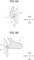
Fig. 5A is an enlarged view of a part V A ofFig. 3B circled by a dash-dot line; -
Fig. 5B is an enlarged view of a part V B ofFig. 3B circled by a dash-dot line; -
Fig. 6A is a cross-sectional view taken along a line VI A - VI A ofFig. 1A ; -
Fig. 6B is a cross-sectional view taken along a line VI B - VI B ofFig. 1A ; -
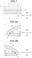
Fig. 7 is an enlarged view of a part VII ofFig. 6A circled by a dash-dot line; -
Fig. 8A is an enlarged view of a part VIII A ofFig. 6B circled by a dash-dot line; -
Fig. 8B is an enlarged view of a part VIII B ofFig. 6B circled by a dash-dot line; -
Fig. 9A is a schematic cross-sectional view in an up-down direction of the scientific calculator, in a second state, with the cover on its back; -
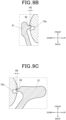
Fig. 9B is an enlarged view of a part IX B ofFig. 9A circled by a dash-dot line; -
Fig. 9C is an enlarged view of a part IX C ofFig. 9A circled by a dash-dot line; -
Fig. 10A is a schematic cross-sectional view in the up-down direction of the scientific calculator, in a second state, with the cover on its front; -
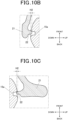
Fig. 10B is an enlarged view of a part X B ofFig. 10A circled by a dash-dot line; -
Fig. 10C is an enlarged view of a part X C ofFig. 10A circled by a dash-dot line; -
Fig. 11A is a schematic cross-sectional view in a left-right direction of the scientific calculator, in a second state, with the cover on its back; -
Fig. 11B is an enlarged view of a part XI B ofFig. 11A circled by a dash-dot line; -
Fig. 12A is a schematic cross-sectional view in the left-right direction of the scientific calculator, in a second state, with the cover on its front; -
Fig. 12B is an enlarged view of a part XII B ofFig. 12A circled by a dash-dot line; and -
Fig. 12C is an enlarged view of a part XII C ofFig. 12A circled by a dash-dot line. - Hereinafter, one or more embodiments of the present disclosure will be described with reference to the
Figs. 1 to 12C . The embodiment described below is provided with various limitations technically preferable for carrying out the present disclosure. However, the scope of the present disclosure is not limited to the embodiment below or illustrated examples. - As shown in
Fig. 1A , anelectronic device 100 according to the present embodiment includes a scientific calculator (electronic device main body) 10 and acover 20. In the description given below, the directions of front, back, left, right, up, and down refer to the directions shown in the drawings. That is, the front-back direction refers to a direction of the front side to back side (thickness direction) of thescientific calculator 10 and thecover 20, the left-right direction refers to a width direction of thescientific calculator 10 and thecover 20, and the up-down direction refers to a longitudinal direction of thescientific calculator 10 and thecover 20. Thecover 20 can be attached to both the front and back sides of thescientific calculator 10, but in the configuration of thecover 20 hereinafter described, the front-back orientation of thecover 20 is as thecover 20 is attached onto the back side of thescientific calculator 10 as shown inFig. 1A , unless otherwise specified. - As shown in
Figs. 1A and2A , thescientific calculator 10 is an example of the electronic device main body according to the present disclosure, and is formed in a rectangular plate shape elongated in the up-down direction. Thescientific calculator 10 includes afront case 11 covering the front face and aback case 15 covering the back face, as shown inFigs. 3A and 3B . Thefront case 11 and theback case 15 engage with each other in the front-back direction to form the housing of thescientific calculator 10. Thefront case 11 and theback case 15 are fastened with multiple screws (not shown in the drawings), for example. Adisplay screen 12 on which various kinds of information are displayed andmultiple operation buttons 13 with which user operations are input are provided on thefront case 11. - The
cover 20 covers and protects the main face (front face or back face) of thescientific calculator 10. As shown inFigs. 1B and2B , thecover 20 is in a shape corresponding to the front-view shape of thescientific calculator 10, that is, in a rectangular plate shape elongated in the up-down direction corresponding to the longitudinal direction of thescientific calculator 10. Thecover 20 is made of, for example, acrylonitrile butadiene styrene (ABS) resin. The periphery of thecover 20 curves forward to cover the periphery of thescientific calculator 10 when attached thereto. - Extending
parts 21 that curve forward and extend outward more than the other part of the periphery of thecover 20 are provided respectively at the upper and lower ends of thecover 20. The extendingparts 21 cover at least part of the side faces (lateral faces) of the upper and lower ends of the housing (the back case 15) of thescientific calculator 10, as shown inFig. 3 . At the end of each of the extendingparts 21, an engagingpart 22 that protrudes toward the center of thecover 20 in the up-down direction is provided. As shown inFig. 4A to 5B , the engagingparts 22 can engage with stoppinggrooves 15a (stopper) from both the front and back sides. The stoppinggrooves 15a are formed on the upper and lower end faces of the housing (the back case 15) of thescientific calculator 10. Thus, thecover 20 can be attached onto each of the front and back sides of thescientific calculator 10 by reversing the orientation in the front-back direction. In the present embodiment, the engagingparts 22 have a protruding shape and the stoppinggrooves 15a (stopper) have a groove shape. But their shapes are not limited to these. The engaging parts may have a groove shape and the stoppers may have a protruding shape. - As shown in
Figs. 3A, 3B ,6A, and 6B , thecover 20 can be placed selectively on both the front and back sides of thescientific calculator 10, and in the first state, the engagingparts 22 are engaged with the stoppinggrooves 15a while thecover 20 is not elastically deformed by being pressed. As shown inFigs. 4A to 5B , an amount of engagement of theengaging part 22 and the stoppinggroove 15a in the first state is a first engagement amount H1. The engagement amount is substantially equal between when thecover 20 is attached onto the front side of thescientific calculator 10 and when it is attached onto the back side, and the average value thereof is 1.0 mm (Here, "substantially equal" means that a difference between each of the engagement amounts and the average value thereof is 400 or less (more preferably 20 % or less.)). As shown inFigs. 6A and7 , a first gap A with a distance W1 is formed between thecover 20 and theback case 15 at the central part in the up-down and left-right directions when thecover 20 is attached onto the back side of thescientific calculator 10 in the first state (a position where the distance of the gap between thecover 20 and thescientific calculator 10 is smallest). The distance W1 of the first gap A is 0.1 mm or more and 1.2 mm or less, and preferably 0.2 mm or more and 0.9 mm or less. - As shown in
Figs. 6B ,8A, and 8B , the a second gap B with a distance W2 is formed between thecover 20 and theback case 15 at the central part in the up-down direction at both ends in the left-right direction (a position where the distance of the gap between thecover 20 and thescientific calculator 10 is smallest) when thecover 20 is attached onto the front side of thescientific calculator 10 in the first state. The distance W2 of the second gap B is in a first range, which is 0.1 mm or more and 1.2 mm or less, and preferably 0.2 mm or more and 0.9 mm or less, specifically. In the present embodiment, the distances W1 and W2 are substantially equal (Here, "substantially equal" means that a difference between the distances W1 and W2 is 0.9 mm or less (more preferably 0.5 mm or less), or a difference between each of the distances W1 and W2 and the average value thereof is 80% or less (more preferably 500 or less.)). As shown inFigs. 6B ,8A, and 8B , the distance W2 of the second gap B when thecover 20 is attached onto the front side of thescientific calculator 10 in the first state is the smallest between thecover 20 and the peripheral part where theoperation buttons 13 are not disposed on the housing of the scientific calculator 10 (the front case 11). A distance W3, the smallest distance between the front face of theoperation buttons 13 not pressed and thecover 20 is in a second range, which is greater than the distance W2 and equal to or smaller than 2.5 mm, specifically. More preferably, the distance W3 is greater than the distance W2 by 0.8 mm and is equal to or smaller than 2.0 mm. - Next described is how the distance of the gap between the
cover 20 and thescientific calculator 10 is determined. If thecover 20 and thescientific calculator 10 are in contact at other parts than the ends in the up-down direction where the stoppinggrooves 15a and the engagingparts 22 are provided when thecover 20 is attached onto the front or back side of thescientific calculator 10, the surface of thescientific calculator 10 might be damaged over time. Therefore a gap is provided between thecover 20 and thescientific calculator 10. The necessary distance of the gap is 0.1 mm or more, and preferably 0.2 mm or more considering tolerances of design variables. - When a user of the
electronic device 100 presses down (or pulls) the extendingparts 21 where the engagingparts 22 of thecover 20 are provided to remove thecover 20 from thescientific calculator 10, the user may press thecover 20 toward thescientific calculator 10 at the central part in the up-down direction. As the gap is formed between thecover 20 and thescientific calculator 10 as described above, thecover 20 is elastically deformed in response to the pressure, and the engagingparts 22 of thecover 20 are thereby moved outward. In this occasion, as the engagement of the stoppinggroove 15a and theengaging part 22 gets smaller, the force of pressing (pulling) the extendingpart 21 required to detach theengaging part 22 from the stoppinggroove 15a is alleviated (the cover can be removed more easily). - As shown in
Figs. 9A to 12C , in the second state, thecover 20 is pressed toward thescientific calculator 10 at the central part in the up-down direction from the first state and is thereby elastically deformed. As shown inFigs. 9B, 9C ,10B, and 10C , the engagement amount of theengaging part 22 and the stoppinggroove 15a in the second state is a second engagement amount H2, which is smaller than the first engagement amount H1. The engagement amount is substantially equal between when thecover 20 is attached onto the front side of thescientific calculator 10 and when it is attached onto the back side, and the average value thereof is 0.93 mm (Here, "substantially equal" means that a difference between each of the engagement amounts and the average value thereof is 400 or less (more preferably 20 % or less.)). That is, the second engagement amount H2 is a front-attachment engagement amount, which is an engagement amount between theengaging part 22 and the stoppinggroove 15a when thecover 20 is elastically deformed so that the central part in the longitudinal direction of thecover 20 is in contact with thescientific calculator 10 in the second state while thecover 20 is attached onto the front side of thescientific calculator 10, and the second engagement amount H2 is also a back-attachment engagement amount, which is an engagement amount between theengaging part 22 and the stoppinggroove 15a when thecover 20 is elastically deformed so that the central part in the longitudinal direction of thecover 20 is in contact with thescientific calculator 10 in the second state while thecover 20 is attached onto the back side of thescientific calculator 10. The shape of thescientific calculator 10, the position of the stoppinggroove 15a, the shape of thecover 20 and the position of theengaging part 22 are determined so that the front-attachment engagement amount and the back-attachment engagement amount are substantially equal. - However, when the second engagement amount H2 in the second state gets smaller than expected, the engagement force gets unstable. The
cover 20 may thereby be removed too easily when being pressed toward thescientific calculator 10. In that case, when thecover 20 is pressed toward thescientific calculator 10 unintentionally when it is being carried around, for example, thecover 20 may be removed from thescientific calculator 10, which is undesirable. Therefore, the ratio of the second engagement amount H2 to the first engagement amount H1 is to be in a range of 30% or more and 95% or less, and the distance W1 of the first gap A or the distance W2 of the second gap B is to be 1.2 mm or less. When it is more important to stably attach thecover 20 to thescientific calculator 10 than to easily remove thecover 20, the ratio of the second engagement amount H2 to the first engagement amount H1 may be 500 or more, or the distance W1 of the first gap A and the distance W2 of the second gap B may be 0.9 mm or less. When it is more important to easily remove thecover 20 using the gap between thecover 20 and thescientific calculator 10, the ratio of the second engagement amount H2 to the first engagement amount H1 may be 80% or less, and the distance W1 of the first gap A or the distance W2 of the second gap B may be 0.2 mm or more, because, with the distance W1 of the first gap A or the distance W2 of the second gap B being small, the amount of deflection is not sufficient at the time of elastic deformation of thecover 20 pressed toward thescientific calculator 10 and the degree of the ease of removal of thecover 20 is small. - If the difference between the distance W1 of the first gap A and the distance W2 of the second gap B is large, the ease of removal of the
cover 20 is different between when thecover 20 is attached onto the front side of thescientific calculator 10 and when it is attached onto the back side of thescientific calculator 10. Therefore, the distance W1 of the first gap A and the distance W2 of the second gap B are to be substantially equal (Here, "substantially equal" means that a difference between the distance W1 and the distance W2 is a predetermined value or less, and for example, is 0.9 mm or less (more preferably 0.5 mm or less).) or the second engagement amount H2 is to be substantially equal between when thecover 20 is attached onto the front side of thescientific calculator 10 and when it is attached onto the back side of the scientific calculator 10 (Here, "substantially equal" means that a difference between each of the engagement amounts and the average value thereof is 400 or less (more preferably 20 % or less).) so that the ease of removal of thecover 20 is not significantly different between when thecover 20 is attached onto the front side of thescientific calculator 10 and when it is attached onto the back side of thescientific calculator 10. - The space-saving and designing of the
electronic device 100 are taken into consideration as follows. When the distance W1 of the first gap A or the distance W2 of the second gap B is larger than 1.2 mm, meaning that the width (thickness) in the front-back direction of the electronic device 100 (thescientific calculator 10 with thecover 20 attached) increases, the space-saving and designing of theelectronic device 100 are degraded. This solution is not preferable because the amount of deflection at the time of elastic deformation of thecover 20 pressed toward thescientific calculator 10 is too large, which may lead to the user discomfort or cause other problems. That is, as the distance W1 of the first gap A and the distance W2 of the second gap B is 0.1 mm or more (preferably 0.2 mm or more) and 1.2 mm or less (preferably 0.9 mm or less), thecover 20 can be stably attached to thescientific calculator 10 while the ease of removal of thecover 20 is improved. In other words, the distance W1 of the first gap A and/or the distance W2 of the second gap B are determined according to the conditions of the stability of attachment of thecover 20 to the electronic device main body (scientific calculator 10) and the ease of removal of thecover 20 from the electronic device main body (scientific calculator 10). - In conventional covers and scientific calculators, a distance formed between a scientific calculator and its cover when the cover is attached onto the back side of the scientific calculator is smaller than the distance W1 of the first gap A according to the present embodiment. Thus, the amount of deflection at the time of elastic deformation of a conventional cover pressed toward a scientific calculator is not sufficient, which makes it hard to remove the cover. Regarding this problem, the value of the distance of the first gap A according to the present embodiment is determined so that the
cover 20 can be removed when thecover 20 is attached onto the back side of thescientific calculator 10 as described above. Moreover, the value of the distance of the first gap A according to the present embodiment is determined so that thecover 20 can be stably attached to thescientific calculator 10 as described above. - In conventional covers and scientific calculators, a cover which is attached onto the front side of a scientific calculator is removed, the cover and operation buttons provided on the front face of the scientific calculator may be brought into contact when the cover is pressed toward the scientific calculator at the central part in the up-down direction. In that case, when the cover is pressed toward the scientific calculator while the cover and the operation buttons are already in contact, the operation buttons are moved in the back direction adding a reaction force to the cover (the maximum stroke amount of the operation buttons is 0.6 mm to 1.0 mm.). Therefore, the force of pressing the cover and the force of deflection of elastic deformation of the cover are unstable, and the ease of removal of the cover is also unstable when the cover is attached onto the front side of the scientific calculator.
- Regarding this problem, when the
cover 20 is attached onto the front side of thescientific calculator 10 in the second state according to the present embodiment, thecover 20 and thescientific calculator 10 are brought into contact first in a region R2, the central part in the up-down direction at both ends in the left-right direction where theoperation buttons 13 are not mounted, as shown inFigs. 12B and 12C . That is, when thecover 20 is attached onto the front side of thescientific calculator 10 in the second state according to the present embodiment, thecover 20 and theoperation buttons 13 are not brought into contact first. Therefore, the ease of removal of thecover 20 when thecover 20 is attached onto the front side of thescientific calculator 10 can be stable. - As shown in
Fig. 11B , when thecover 20 is attached onto the back side of thescientific calculator 10 in the second state, thecover 20 and thescientific calculator 10 are in contact in the region R1, the central part in the up-down and the left-right directions. - As shown in
Figs. 6A and 6B , the degree of curving at both ends in the left-right direction of theelectronic device 10 is larger on the front side than on the back side and the degree of curving at both ends in the left-right direction of thecover 20 is equal to or smaller than the degree of curving at both ends in the left-right direction of theelectronic device 10 on the back side. Thus, when thecover 20 is attached onto the front side of thescientific calculator 10 in the second state, thecover 20 can be in contact with thescientific calculator 10 in the region R2, the central part in the up-down direction at both ends in the left-right direction where theoperation buttons 13 are not mounted, as shown inFigs. 12B and 12B , and when thecover 20 is attached onto the back side of thescientific calculator 10 in the second state, thecover 20 can be in contact with thescientific calculator 10 in the region R1, the central part in the up-down and the left-right directions, as shown inFigs. 11A and 11B . - In conventional covers and scientific calculators, the ease of removal of a cover is different between when the
cover 20 is attached onto the front side of thescientific calculator 10 and when it is attached onto the back side of thescientific calculator 10 because the amount of deflection at the time of elastic deformation of the cover pressed toward the scientific calculator is different and the ease of removal of the cover is thereby unstable. Regarding this problem, the distance W1 of the first gap A and the distance W2 of the second gap B according to the present embodiment are substantially equal, and the difference between the distance W1 and the distance W2 is 0.9 mm or less (more preferably 0.5 mm or less). That is, the amount of deflection at the time of elastic deformation of thecover 20 pressed toward thescientific calculator 10 is unchanged between when thecover 20 is attached onto the back side of thescientific calculator 10 and when thecover 20 is attached onto the front side of thescientific calculator 10. Therefore, the ease of removal of thecover 20 is substantially equal between when thecover 20 is attached onto the back side of thescientific calculator 10 and when thecover 20 is attached onto the front side of thescientific calculator 10, and the ease of removal of thecover 20 is stable. In other words, the difference between the distance W1 of the first gap A and the distance W2 of the second gap B is determined according to the conditions of the difference between the ease of removal of thecover 20 attached on the front side of the electronic device main body (the scientific calculator 10) and the ease of removal of thecover 20 attached on the back side of the electronic device main body. - The
electronic device 100 according to the embodiment above may satisfy at least one of the first condition, the second condition, and the third condition shown below. The first condition is that thecover 20 and thescientific calculator 10 are in contact in a region where theoperation buttons 13 are not mounted when thecover 20 is attached onto the front side of thescientific calculator 10 in the second state as shown inFigs. 12B and 12C . The second condition is that the first gap A is formed between thecover 20 and thescientific calculator 10 at the central part in the up-down direction when thecover 20 is attached onto the back side of thescientific calculator 10 in the first state as shown inFig. 7 . The third condition is that the distance W1 of the first gap A is substantially equal as the distance W2 of the second gap B formed between thecover 20 and thescientific calculator 10 at the central part in the up-down direction when thecover 20 is attached onto the front side of thescientific calculator 10 in the first state. In this case, the ease of removal of thecover 20 from thescientific calculator 10 can also be appropriate. - The ease of removal of the
cover 20 from thescientific calculator 10 depends on the shapes and hardness of thecover 20, the engagingparts 22, thefront case 11, theback case 15, the stoppinggrooves 15a, and the like. In the embodiment described above, the distance W1 of the first gap A and the distance W2 of the second gap B are determined assuming that thescientific calculator 10 is in the shape and size of a standard scientific calculator (roughly a rectangular shape with: depth of 150 to 200 mm; width of 60 to 90 mm; and height of 10 to 20 mm) and that the material of thecover 20 is ABS resin (polystyrene (PS) or other materials may also be used as long as it has a Young's modulus similar to ABS resin), which is commonly used. However, on the contrary, at least one of the shape of thecover 20, the hardness of thecover 20, the shape of the housing of the scientific calculator 10 (thefront case 11 and the back case 15), the hardness of the housing of thescientific calculator 10, the shape of the engagingparts 22, the hardness of the engagingparts 22, the shape of the stoppinggrooves 15a, and the hardness of the stoppinggrooves 15a may be determined based on the distance W1 of the first gap A and/or the distance W2 of the second gap B. In a case where the size of the electronic device as the target of application exemplified by thescientific calculator 10 is different, the distances of the gaps and the engagement amounts described above may be changed proportionally to the difference of the size. - Next, the
electronic device 100 according to a variation of the embodiment described above is described. The following description is given focusing on the differences from theelectronic device 100 according to the above embodiment. The components similar to those of theelectronic device 100 according to the above embodiment are described with the same reference signs and the descriptions thereof are omitted. - In this variation, when the
cover 20 is attached onto the front side of thescientific calculator 10 in the second state as shown inFigs. 12A to 12C , thecover 20 and thescientific calculator 10 are brought into contact first in the region R2, the central part in the up-down direction at both ends in the left-right direction where theoperation buttons 13 are not mounted. Next, when thecover 20 is pressed toward thescientific calculator 10 while thecover 20 and thescientific calculator 10 are in contact in the region R2, thecover 20 and the surface of theoperation buttons 13 are brought into contact. However, as thecover 20 and thescientific calculator 10 are already in contact in the region R2 and thecover 20 is supported at the region R2, the surface of theoperation buttons 13 are not easily damaged. - In addition, a rib or a protrusion may be provided on the face of the
cover 20 on the side of thescientific calculator 10. In that case, when thecover 20 is attached onto the front side of thescientific calculator 10, thecover 20 can be prevented from being brought into contact with theoperation buttons 13 as the rib or protrusion is in contact with thefront case 11 in a region between theoperation buttons 13. - As described hereinbefore, the
electronic device 100 according to the present embodiment includes the electronic device main body (scientific calculator 10) and thecover 20. The electronic device main body (scientific calculator 10) has the stopper (stoppinggroove 15a) on both sides in the longitudinal direction, and thecover 20 can be attached to the electronic device main body (scientific calculator 10) selectively on front side or the back side and is provided with the engagingparts 22 that engage with the stoppers in the first state where there is a gap between the electronic device main body (scientific calculator 10) and thecover 20 in the central part in the longitudinal direction regardless of whether thecover 20 is attached onto the front side or the back side. In theelectronic device 100, the amount of engagement of theengaging part 22 and thestopper 15 when thecover 20 is attached onto the front side of the electronic devicemain body 10 in the second state where thecover 20 is elastically deformed to be brought into contact with the electronic devicemain body 10 at the central part in the longitudinal direction of thecover 20 is defined as a front-side attachment engagement amount. The amount of engagement of theengaging part 22 and thestopper 15 when the cover is attached onto the back side of the electronic device main body in the second state where thecover 20 is elastically deformed to be brought into contact with the electronic devicemain body 10 at the central part in the longitudinal direction of thecover 20 is defined as a back-side attachment engagement amount. The shape of the electronic device main body and the positions of thestoppers 15 and the shape of thecover 20 and the positions of the engagingparts 22 are determined such that the front-side attachment engagement amount and the back-side attachment engagement amount are substantially equal. That is, the gap in the first state is determined so that the front-side attachment engagement amount and the back-side attachment engagement amount are substantially equal. Thus, the ease of removal of thecover 20 does not differ significantly between when thecover 20 is attached onto the front side of thescientific calculator 10 and when it is attached onto the back side. The ease of removal of thecover 20 from thescientific calculator 10 can thereby be appropriate. - The
electronic device 100 according to the present embodiment includes the electronic device main body (scientific calculator 10) that includesmultiple operation buttons 13 and thecover 20 that can be attached to the electronic device main body. The electronic device main body includes the stoppers 15 (stoppinggrooves 15a) respectively on both sides in the longitudinal direction thereof. Thecover 20 includes the extendingparts 21 that are respectively provided at both ends and that cover the side faces (lateral faces) of the electronic device main body at least partially and the engagingparts 22 that are provided at the tips of the extendingparts 21 and that engage with the stoppers. In the first state, the engagement amount of theengaging part 22 and the stopper is the first engagement amount H1 when thecover 20 is attached onto the front side or the back side of the electronic device main body. In the second state when thecover 20 is pressed toward the electronic device main body at the central part in the longitudinal direction of thecover 20 from the first state, the engagement amount of theengaging part 22 and the stopper is the second engagement amount H2, which is smaller than the first engagement amount H1. The gap formed at the central part in the longitudinal direction between thecover 20 and the electronic device main body at a position where the gap is smallest when thecover 20 is attached onto the back side of the electronic device main body in the first state is defined as the first gap A, and the gap formed at the central part in the longitudinal direction between thecover 20 and the electronic device main body at a position where the gap is smallest when thecover 20 is attached onto the front side of the electronic device main body in the second state is defined as the second gap B. The distance W1 of the first gap is substantially equal to the distance W2 of the second gap B. As a result, the amount of deflection at the time of elastic deformation of thecover 20 pressed toward thescientific calculator 10 is unchanged between when thecover 20 is attached onto the back side of thescientific calculator 10 and when thecover 20 is attached onto the front side of thescientific calculator 10. Thus, the ease of removal of thecover 20 is substantially equal between when thecover 20 is attached onto the back side of thescientific calculator 10 and when thecover 20 is attached onto the front side of thescientific calculator 10, and the ease of removal of thecover 20 from thescientific calculator 10 can also be appropriate. - The
electronic device 100 according to the present embodiment includes the electronic device main body (scientific calculator 10) that includesmultiple operation buttons 13 and thecover 20 that can be attached to the electronic device main body. The electronic device main body includes the stoppers 15 (stoppinggrooves 15a) respectively on both sides in the longitudinal direction thereof. Thecover 20 includes the extendingparts 21 that are respectively provided at both ends and that cover the side faces (lateral faces) of the electronic device main body at least partially and the engagingparts 22 that are provided at the tips of the extendingparts 21 and that engage with the stoppers. In the first state, the engagement amount of theengaging part 22 and the stopper is the first engagement amount H1 when thecover 20 is attached onto the front side or the back side of the electronic device main body. In the second state when thecover 20 is pressed toward the electronic device main body at the central part in the longitudinal direction of thecover 20 from the first state, the engagement amount of theengaging part 22 and the stopper is the second engagement amount H2, which is smaller than the first engagement amount H1. In theelectronic device 100, the gap formed between thecover 20 and the electronic device main body at the central part in the longitudinal direction when thecover 20 is attached onto the front side of the electronic device main body in the first state is the narrowest in an area where theoperation buttons 13 are not mounted. When thecover 20 is attached onto the front side of the electronic devicemain body 10 in the second state, thecover 20 is in contact with the electronic device main body in the area where theoperation buttons 13 are not mounted, and thecover 20 is not in contact with the electronic device main body in the area where the plurality ofoperation buttons 13 are mounted. Thus, thecover 20 is not brought into contact with theoperation buttons 13 even when thecover 20 is pressed toward thescientific calculator 10. As a result, it is possible to prevent the instability of the force of pressing thecover 20 and the amount of deflection of thecover 20 at the time of elastic deformation, the instability being caused by the movement of theoperation buttons 13 in the back direction with a reaction force being added to thecover 20 when thecover 20 is pressed toward thescientific calculator 10. That is, the ease of removal of thecover 20 when thecover 20 is attached onto the front side of thescientific calculator 10 can be appropriate. - In the
electronic device 100 according to the present embodiment, thecover 20 and the electronic device main body (scientific calculator 10) are in contact at the central part in the longitudinal direction at the both ends in the left-right direction where theoperation buttons 13 are not mounted when thecover 20 is attached onto the front side of the electronic device main body (scientific calculator 10) in the second state. Thus, thecover 20 is not brought into contact with theoperation buttons 13 even when thecover 20 is pressed toward thescientific calculator 10. As a result, it is possible to prevent the instability of the force of pressing thecover 20 and the amount of deflection of thecover 20 at the time of elastic deformation, the instability being caused by the movement of theoperation buttons 13 in the back direction with a reaction force being added to thecover 20 when thecover 20 is pressed toward thescientific calculator 10. That is, the ease of removal of thecover 20 when thecover 20 is attached onto the front side of thescientific calculator 10 can be appropriate. - In the
electronic device 100 according to the present embodiment, in the second state, thecover 20 is first brought into contact with any part of the electronic device main body (scientific calculator 10) when thecover 20 is pressed toward the electronic device main body (scientific calculator 10) at the central part in the longitudinal direction to be elastically deformed from the first state. Thus, as the area where thecover 20 and the electronic device main body are first brought into contact is where theoperation buttons 13 are not mounted, thecover 20 and theoperation buttons 13 are not in contact in the second state. That is, it is possible to prevent the instability of the force of pressing thecover 20 and the amount of deflection of thecover 20 at the time of elastic deformation, the instability being caused by the movement of theoperation buttons 13 in the back direction with a reaction force being added to thecover 20 when thecover 20 is pressed toward thescientific calculator 10. - In the
electronic device 100 according to the present embodiment, the gap between the distance W1 of the first gap A and the distance W2 of the second gap B is equal to or smaller than 40% with respect to the average value of the distance W1 of the first gap A and the distance W2 of the second gap B. As a result, the amount of deflection at the time of elastic deformation of thecover 20 pressed toward thescientific calculator 10 is unchanged between when thecover 20 is attached onto the back side of thescientific calculator 10 and when thecover 20 is attached onto the front side of thescientific calculator 10. Therefore, the ease of removal of thecover 20 is substantially equal between when thecover 20 is attached onto the back side of thescientific calculator 10 and when thecover 20 is attached onto the front side of thescientific calculator 10, and the ease of removal of thecover 20 from thescientific calculator 10 can be appropriate. - In the
electronic device 100 according to the present embodiment, when thecover 20 is attached onto the front side of the electronic device main body in the first state, the smallest gap between thecover 20 and the peripheral part of the electronic device main body where theoperation buttons 13 are not mounted is in the first range, and the gap between the front of theoperation buttons 13 and thecover 20 not pressed is in the second range, where the minimum value of the second range is greater than the maximum value of the first range. Thus, thecover 20 is not brought into contact with theoperation buttons 13 even when thecover 20 is pressed toward thescientific calculator 10. As a result, it is possible to prevent the instability of the force of pressing thecover 20 and the amount of deflection of thecover 20 at the time of elastic deformation, the instability being caused by the movement of theoperation buttons 13 in the back direction with a reaction force being added to thecover 20 when thecover 20 is pressed toward thescientific calculator 10. That is, the ease of removal of thecover 20 when thecover 20 is attached onto the front side of thescientific calculator 10 can be appropriate. - In the
electronic device 100 according to the present embodiment , the distance W1 of the first gap A and/or the distance W2 of the second gap B is determined according to a condition that allows thecover 20 to be removed easily and attached stably, based on the shape of thecover 20 and the shape of the housing of the electronic device main body in a case where the electronic device main body (scientific calculator 10) is an electronic desktop calculator in a standard size and shape. This makes it possible to improve the ease of removal of thescientific calculator 10 from thecover 20 and the stability of attachment of thescientific calculator 10 onto thecover 20. - In the
electronic device 100 according to the present embodiment, the gap between the distance W1 of the first gap A and the distance W2 of the second gap B is determined according to a condition that allows the ease of removal of thecover 20 to be substantially equal between when thecover 20 is attached onto the front side of the electronic device main body and when thecover 20 is attached onto the back side of the electronic device main body based on the shape of thecover 20, the hardness of thecover 20, and the shape of the electronic device main body (scientific calculator 10) in a case where the electronic device main body (scientific calculator 10) is an electronic desktop calculator in a standard size and shape and thecover 20 is made of standard materials. As a result, the ease of removal of thecover 20 is substantially equal between when thecover 20 is attached onto the back side of thescientific calculator 10 and when thecover 20 is attached onto the front side of thescientific calculator 10, and the ease of removal of thecover 20 from thescientific calculator 10 can be appropriate. - The embodiments to which the present invention can be applied are not limited to the above-described embodiments, and various modifications can be made without departing from the scope of the present disclosure. For example, the electronic device main body according to the present disclosure is not limited to the scientific calculator (electronic desktop calculator), and the present disclosure may be applied to electronic devices in general the main face of which is protected by a cover.
- Although one or more embodiments have been described, the scope of the present invention is not limited to the embodiments and includes the scope of claims below and the scope of their equivalents.
Claims (11)
- An electronic device (100) comprising:an electronic device main body (10); anda cover (20) that can be attached selectively onto a front side or back side of the electronic device main body (10),wherein the electronic device main body (10) includes a stopper (15a) on each of lateral faces at both ends in a longitudinal direction,wherein the cover (20) includes, at each of both ends in the longitudinal direction, an engaging part (22) that engages with the stopper (15a), in a first state where there is a gap between the cover (20) and the electronic device main body (10) at a central part in the longitudinal direction regardless of whether the cover (20) is attached onto the front side or the back side of the electronic device main body (10),wherein the gap is formed such that a front-side attachment engagement amount and a back-side attachment engagement amount are substantially equal, the front-side attachment engagement amount being an amount (H2) of engagement of the engaging part (22) and the stopper (15a) when the cover is attached onto the front side of the electronic device main body (10) in a second state where the cover (20) is elastically deformed to be brought into contact with the electronic device main body (10) at the central part in the longitudinal direction of the cover (20), and the back-side attachment engagement amount being an amount (H2) of engagement of the engaging part (22) and the stopper (15) when the cover is attached onto the back side of the electronic device main body in the second state where the cover (20) is elastically deformed to be brought into contact with the electronic device main body (10) at the central part in the longitudinal direction of the cover (20) .
- The electronic device (100) according to claim 1,
wherein regardless of whether the cover (20) is attached onto the front side of the electronic device main body (10) or the back side of the electronic device main body (10), the amount (H2) of engagement of the stopper (15a) and the engaging part (22) in the second state is smaller than an amount (H1) of engagement of the stopper (15a) and the engaging part (22) in the first state. - The electronic device (100) according to claim 1 or 2,
wherein a first distance (W1) of a first gap (A) and a second distance (W2) of a second gap (B) are substantially equal, the first gap being formed at the central part in the longitudinal direction between the cover (20) and the electronic device main body (10) when the cover (20) is attached onto the back side of the electronic device main body (10) in the first state, the second gap being formed at the central part in the longitudinal direction when the cover (20) is attached onto the front side of the electronic device main body (10) in the second state, the first distance being measured at a position where the first gap is smallest, and the second distance being measured at a position where the second gap is smallest. - The electronic device according to claim 3,wherein the electronic device main body (10) includes a plurality of operation buttons (13) on the front side,wherein the second gap (B) is formed in an area where the plurality of operation buttons (13) is not mounted,wherein when the cover (20) is attached onto the front side of the electronic device main body (10) in the second state, the cover (20) is in contact with the electronic device main body (10) in the area where the plurality of operation buttons (13) is not mounted, and the cover (20) is not in contact with the electronic device main body (10) in an area where the plurality of operation buttons (13) is mounted.
- The electronic device according to claim 3 or 4,wherein the first gap (A) is formed at a central part in a left-right direction of the electronic device main body (10),wherein the second gap (B) is formed at both ends in the left-right direction of the electronic device main body (10) .
- The electronic device according to any one of claims 1 to 5,wherein a degree of curving of the electronic device main body (10) at both ends in a left-right direction of the electronic device main body (10) is greater on the front side than the back side,wherein a degree of curving of the cover (20) at both ends in the left-right direction of the cover (20) is equal to or smaller than the degree of the curving of the electronic device main body (10) at the both ends in the left-right direction of the electronic device main body (10) on the back side.
- The electronic device according to any one of claims 1 to 6,wherein the cover (20) includes an extending part (21) that covers each of the lateral faces of the electronic device main body (10) at least partially,wherein the engaging part (22) is provided at a tip of the extending part (21).
- The electronic device according to any one of claims 1 to 7,
wherein when the cover (20) is attached onto the electronic device main body (10) in the second state, the electronic device main body (10) is in contact with the cover (20) at the central part in the longitudinal direction at both ends in a left-right direction of the electronic device main body. - The electronic device according to any one of claims 1 to 7,
wherein in the second state, the cover 20 is brought into contact first with any part of the electronic device main body (10) when the cover (20) is pressed toward the electronic device main body (10) at the central part in the longitudinal direction to be elastically deformed from the first state. - The electronic device according to any one of claims 3 to 5,
wherein the first distance (W1) of the first gap (A) and/or the second distance (W2) of the second gap (B) is determined according to a condition that allows the cover (20) to be removed easily and attached stably, based on a shape of the cover (20) and a shape of a housing of the electronic device main body (10). - The electronic device according to any one of claims 3 to 5,
wherein a difference between the first distance (W1) of the first gap (A) and the second distance (W2) of the second gap (B) are determined according to a condition that allows the cover 20 to be removed when the cover 20 is attached onto the front side of the electronic device main body (10) as easily as when the cover 20 is attached onto the back side of the electronic device main body (10), based on a shape of the cover (20), a hardness of the cover (20), and a shape of a housing of the electronic device main body (10).
Applications Claiming Priority (1)
| Application Number | Priority Date | Filing Date | Title |
|---|---|---|---|
| JP2023211047A JP7732493B2 (en) | 2023-12-14 | 2023-12-14 | Covered electronic devices |
Publications (2)
| Publication Number | Publication Date |
|---|---|
| EP4571454A1 true EP4571454A1 (en) | 2025-06-18 |
| EP4571454B1 EP4571454B1 (en) | 2026-04-22 |
Family
ID=93460851
Family Applications (1)
| Application Number | Title | Priority Date | Filing Date |
|---|---|---|---|
| EP24211741.4A Active EP4571454B1 (en) | 2023-12-14 | 2024-11-08 | Electronic device including cover |
Country Status (2)
| Country | Link |
|---|---|
| EP (1) | EP4571454B1 (en) |
| JP (2) | JP7732493B2 (en) |
Citations (4)
| Publication number | Priority date | Publication date | Assignee | Title |
|---|---|---|---|---|
| JP2003086173A (en) | 2001-09-06 | 2003-03-20 | Shibaura Mechatronics Corp | Liquid injection device and liquid injection method |
| US8072749B1 (en) * | 2010-10-21 | 2011-12-06 | Research In Motion Limited | Push to release cover for a portable electronic device |
| JP2023086173A (en) | 2021-12-10 | 2023-06-22 | カシオ計算機株式会社 | Cover part and electronic device |
| JP2023132405A (en) * | 2022-03-11 | 2023-09-22 | カシオ計算機株式会社 | Cover parts and electronic equipment units |
Family Cites Families (1)
| Publication number | Priority date | Publication date | Assignee | Title |
|---|---|---|---|---|
| JP7567850B2 (en) * | 2021-12-15 | 2024-10-16 | カシオ計算機株式会社 | Electronics |
-
2023
- 2023-12-14 JP JP2023211047A patent/JP7732493B2/en active Active
-
2024
- 2024-11-08 EP EP24211741.4A patent/EP4571454B1/en active Active
-
2025
- 2025-08-06 JP JP2025131877A patent/JP2025161835A/en active Pending
Patent Citations (4)
| Publication number | Priority date | Publication date | Assignee | Title |
|---|---|---|---|---|
| JP2003086173A (en) | 2001-09-06 | 2003-03-20 | Shibaura Mechatronics Corp | Liquid injection device and liquid injection method |
| US8072749B1 (en) * | 2010-10-21 | 2011-12-06 | Research In Motion Limited | Push to release cover for a portable electronic device |
| JP2023086173A (en) | 2021-12-10 | 2023-06-22 | カシオ計算機株式会社 | Cover part and electronic device |
| JP2023132405A (en) * | 2022-03-11 | 2023-09-22 | カシオ計算機株式会社 | Cover parts and electronic equipment units |
Also Published As
| Publication number | Publication date |
|---|---|
| JP7732493B2 (en) | 2025-09-02 |
| JP2025095200A (en) | 2025-06-26 |
| JP2025161835A (en) | 2025-10-24 |
| EP4571454B1 (en) | 2026-04-22 |
Similar Documents
| Publication | Publication Date | Title |
|---|---|---|
| US10429900B1 (en) | Coupled structure and electronic device | |
| JP6551043B2 (en) | Information processing device | |
| US20170052611A1 (en) | Information processing apparatus and base member | |
| EP4571454B1 (en) | Electronic device including cover | |
| JP2009253051A (en) | Structure for attaching and detaching case and fixed base | |
| JP7666714B2 (en) | Electronics Unit | |
| EP4446902A1 (en) | Cover component and electronic apparatus | |
| US8132975B2 (en) | Keyboard stiffening system | |
| WO2013015107A1 (en) | Piezoelectric excitor | |
| JP6386504B2 (en) | Name plate mounting structure | |
| WO1998001369A1 (en) | Cassette storage casing | |
| JP2015222379A (en) | Liquid crystal display | |
| US20170192463A1 (en) | Electronic device | |
| JP5142766B2 (en) | Electronics | |
| JP5072659B2 (en) | Electronics | |
| JP4507979B2 (en) | Push switch | |
| JPH0636603Y2 (en) | Panel mounting device | |
| JP3128408U (en) | Information playback device | |
| JP2025117963A (en) | printer | |
| JP2007128740A (en) | Push button device | |
| JP2022086913A (en) | Snap-fit structure and sensor | |
| JP2012248751A (en) | Chassis and chassis mounting structure | |
| JP2017191711A (en) | Key structure mounting structure and electronic device | |
| KR20070068172A (en) | Mobile communication terminal |
Legal Events
| Date | Code | Title | Description |
|---|---|---|---|
| PUAI | Public reference made under article 153(3) epc to a published international application that has entered the european phase |
Free format text: ORIGINAL CODE: 0009012 |
|
| STAA | Information on the status of an ep patent application or granted ep patent |
Free format text: STATUS: REQUEST FOR EXAMINATION WAS MADE |
|
| 17P | Request for examination filed |
Effective date: 20241108 |
|
| AK | Designated contracting states |
Kind code of ref document: A1 Designated state(s): AL AT BE BG CH CY CZ DE DK EE ES FI FR GB GR HR HU IE IS IT LI LT LU LV MC ME MK MT NL NO PL PT RO RS SE SI SK SM TR |
|
| GRAP | Despatch of communication of intention to grant a patent |
Free format text: ORIGINAL CODE: EPIDOSNIGR1 |
|
| STAA | Information on the status of an ep patent application or granted ep patent |
Free format text: STATUS: GRANT OF PATENT IS INTENDED |
|
| INTG | Intention to grant announced |
Effective date: 20251215 |
|
| GRAS | Grant fee paid |
Free format text: ORIGINAL CODE: EPIDOSNIGR3 |
|
| GRAA | (expected) grant |
Free format text: ORIGINAL CODE: 0009210 |
|
| STAA | Information on the status of an ep patent application or granted ep patent |
Free format text: STATUS: THE PATENT HAS BEEN GRANTED |
|
| AK | Designated contracting states |
Kind code of ref document: B1 Designated state(s): AL AT BE BG CH CY CZ DE DK EE ES FI FR GB GR HR HU IE IS IT LI LT LU LV MC ME MK MT NL NO PL PT RO RS SE SI SK SM TR |
|
| REG | Reference to a national code |
Ref country code: CH Ref legal event code: F10 Free format text: ST27 STATUS EVENT CODE: U-0-0-F10-F00 (AS PROVIDED BY THE NATIONAL OFFICE) Effective date: 20260422 Ref country code: GB Ref legal event code: FG4D |
|
| REG | Reference to a national code |
Ref country code: DE Ref legal event code: R096 Ref document number: 602024004182 Country of ref document: DE |