EP4571424A1 - Fixing device and image forming apparatus provided therewith - Google Patents
Fixing device and image forming apparatus provided therewith Download PDFInfo
- Publication number
- EP4571424A1 EP4571424A1 EP24217534.7A EP24217534A EP4571424A1 EP 4571424 A1 EP4571424 A1 EP 4571424A1 EP 24217534 A EP24217534 A EP 24217534A EP 4571424 A1 EP4571424 A1 EP 4571424A1
- Authority
- EP
- European Patent Office
- Prior art keywords
- gear
- fixing device
- fixing
- image forming
- depressurizing
- Prior art date
- Legal status (The legal status is an assumption and is not a legal conclusion. Google has not performed a legal analysis and makes no representation as to the accuracy of the status listed.)
- Pending
Links
Images





Classifications
-
- G—PHYSICS
- G03—PHOTOGRAPHY; CINEMATOGRAPHY; ANALOGOUS TECHNIQUES USING WAVES OTHER THAN OPTICAL WAVES; ELECTROGRAPHY; HOLOGRAPHY
- G03G—ELECTROGRAPHY; ELECTROPHOTOGRAPHY; MAGNETOGRAPHY
- G03G15/00—Apparatus for electrographic processes using a charge pattern
- G03G15/20—Apparatus for electrographic processes using a charge pattern for fixing, e.g. by using heat
- G03G15/2003—Apparatus for electrographic processes using a charge pattern for fixing, e.g. by using heat using heat
- G03G15/2014—Apparatus for electrographic processes using a charge pattern for fixing, e.g. by using heat using heat using contact heat
- G03G15/2017—Structural details of the fixing unit in general, e.g. cooling means, heat shielding means
-
- G—PHYSICS
- G03—PHOTOGRAPHY; CINEMATOGRAPHY; ANALOGOUS TECHNIQUES USING WAVES OTHER THAN OPTICAL WAVES; ELECTROGRAPHY; HOLOGRAPHY
- G03G—ELECTROGRAPHY; ELECTROPHOTOGRAPHY; MAGNETOGRAPHY
- G03G15/00—Apparatus for electrographic processes using a charge pattern
- G03G15/20—Apparatus for electrographic processes using a charge pattern for fixing, e.g. by using heat
- G03G15/2003—Apparatus for electrographic processes using a charge pattern for fixing, e.g. by using heat using heat
- G03G15/2014—Apparatus for electrographic processes using a charge pattern for fixing, e.g. by using heat using heat using contact heat
- G03G15/2017—Structural details of the fixing unit in general, e.g. cooling means, heat shielding means
- G03G15/2032—Retractable heating or pressure unit
-
- G—PHYSICS
- G03—PHOTOGRAPHY; CINEMATOGRAPHY; ANALOGOUS TECHNIQUES USING WAVES OTHER THAN OPTICAL WAVES; ELECTROGRAPHY; HOLOGRAPHY
- G03G—ELECTROGRAPHY; ELECTROPHOTOGRAPHY; MAGNETOGRAPHY
- G03G15/00—Apparatus for electrographic processes using a charge pattern
- G03G15/20—Apparatus for electrographic processes using a charge pattern for fixing, e.g. by using heat
- G03G15/2003—Apparatus for electrographic processes using a charge pattern for fixing, e.g. by using heat using heat
- G03G15/2014—Apparatus for electrographic processes using a charge pattern for fixing, e.g. by using heat using heat using contact heat
- G03G15/2064—Apparatus for electrographic processes using a charge pattern for fixing, e.g. by using heat using heat using contact heat combined with pressure
-
- G—PHYSICS
- G03—PHOTOGRAPHY; CINEMATOGRAPHY; ANALOGOUS TECHNIQUES USING WAVES OTHER THAN OPTICAL WAVES; ELECTROGRAPHY; HOLOGRAPHY
- G03G—ELECTROGRAPHY; ELECTROPHOTOGRAPHY; MAGNETOGRAPHY
- G03G21/00—Arrangements not provided for by groups G03G13/00 - G03G19/00, e.g. cleaning, elimination of residual charge
- G03G21/16—Mechanical means for facilitating the maintenance of the apparatus, e.g. modular arrangements
- G03G21/1642—Mechanical means for facilitating the maintenance of the apparatus, e.g. modular arrangements for connecting the different parts of the apparatus
- G03G21/1647—Mechanical connection means
-
- G—PHYSICS
- G03—PHOTOGRAPHY; CINEMATOGRAPHY; ANALOGOUS TECHNIQUES USING WAVES OTHER THAN OPTICAL WAVES; ELECTROGRAPHY; HOLOGRAPHY
- G03G—ELECTROGRAPHY; ELECTROPHOTOGRAPHY; MAGNETOGRAPHY
- G03G2215/00—Apparatus for electrophotographic processes
- G03G2215/20—Details of the fixing device or porcess
- G03G2215/2003—Structural features of the fixing device
- G03G2215/2016—Heating belt
- G03G2215/2025—Heating belt the fixing nip having a rotating belt support member opposing a pressure member
- G03G2215/2032—Heating belt the fixing nip having a rotating belt support member opposing a pressure member the belt further entrained around additional rotating belt support members
Definitions
- the present disclosure relates to fixing devices incorporated in image forming apparatuses such as multifunction peripherals, printers, facsimile machines, and multifunction peripherals having their functions integrated together, and to image forming apparatuses provided with such a fixing device.
- a fixing device including a fixing member configured with a fixing roller or a fixing belt (a heated rotating member) and a pressing roller (a pressing rotating member) kept in pressed contact with each other.
- This fixing device passes the sheet through a fixing nip portion formed between the fixing roller or the fixing belt and the pressing roller, and heats and presses the toner image to fuse and fix the toner image to the sheet.
- the heated rotating member and the pressing rotating member are kept in pressed contact with each other, and this necessitates a configuration that can relieve the pressure for removal of the sheet when a jam occurs.
- An object of the present disclosure is to enhance the positioning accuracy of a driving member with a simple configuration and to provide a fixing device that can prevent problems such as coupling failure and abnormal noise caused by displacement of a coupling portion, and to provide an image forming apparatus provided with such a fixing device.
- a fixing device includes a fixing member, a housing, a side cover, a pressing mechanism, and a unit side gear, and heats and presses a sheet passing through a fixing nip portion to fuse and fix an unfixed toner image on the sheet.
- the fixing member is configured with a heated rotating member and a pressing rotating member kept in pressed contact with the heated rotating member to form the fixing nip portion.
- the housing houses the fixing member.
- the side cover is fitted to at least one end of the housing in the longitudinal direction.
- the pressing mechanism adjusts the pressure between the heated rotating member and the pressing rotating member.
- the unit side gear is coupled with a main body side gear provided on a main body of an image forming apparatus, and transmits a driving force to the fixing member or the pressing mechanism.
- the side cover has a first positioning portion that positions the unit side gear and a second positioning portion that positions the main body side gear.
- Fig. 1 is a sectional view showing the internal construction of an image forming apparatus 100 according to an embodiment of the present disclosure.
- a main body of the image forming apparatus 100 here, a color printer
- four image forming portions Pa, Pb, Pc, and Pd are arranged in this order from upstream (the left side in Fig. 1 ) in the conveyance direction.
- the image forming portions Pa to Pd are provided so as to correspond to images of four different colors (yellow, cyan, magenta, and black).
- the image forming portions Pa to Pd form yellow, cyan, magenta, and black images sequentially, each through the processes of electrostatic charging, exposure to light, image development, and image transfer.
- photosensitive drums image carrying member 1a, 1b, 1c, and 1d, which carry visible images (toner images) of the different colors.
- An intermediate transfer belt (intermediate transfer member) 8 that rotates counterclockwise in Fig. 1 by being driven by a belt driving motor (not illustrated) is provided adjacent to the image forming portions Pa to Pd.
- the toner images formed on the photosensitive drums 1a to 1d are, by being primarily transferred sequentially to the intermediate transfer belt 8, which moves while in contact with the photosensitive drums 1a to 1d, overlaid on each other.
- the toner images primarily transferred to the intermediate transfer belt 8 are secondarily transferred by a secondary transfer roller 9 to a transfer sheet P as one example of a recording medium.
- the transfer sheet P having the toner images secondarily transferred to it then has the toner images fixed to it in a fixing device 14 and is then discharged out of the main body of the image forming apparatus 100. While the photosensitive drums 1a to 1d are rotated clockwise in Fig. 1 , an image forming process is performed with respect to the photosensitive drums 1a to 1d.
- the transfer sheets P to which toner images will be secondarily transferred are stored inside a sheet cassette 16 arranged in a lower part of the main body of the image forming apparatus 100.
- the transfer sheet P is conveyed via a sheet feed roller 12 and a pair of registration rollers 13 along a sheet conveyance passage 19 to the nip between the secondary transfer roller 9 and a driving roller 11 for the intermediate transfer belt 8.
- Used as the intermediate transfer belt 8 is a sheet of a dielectric resin, typically a belt with no seam (a seamless belt). Downstream of the secondary transfer roller 9, a blade-form belt cleaner 25 for removing toner and the like left on the surface of the intermediate transfer belt 8 is provided.
- the image forming portions Pa to Pd will be described.
- charging devices 2a, 2b, 2c, and 2d which electrostatically charge the photosensitive drums 1a to 1d
- an exposure device 5 which exposes the photosensitive drums 1a to 1d to light conveying image information
- developing device 3a, 3b, 3c, and 3d which form toner images on the photosensitive drums 1a to 1d
- cleaning devices 7a, 7b, 7c, and 7d which remove developer (toner) and the like left on the photosensitive drums 1a to 1d.
- the charging devices 2a to 2d electrostatically charge the surfaces of the photosensitive drums 1a to 1d uniformly.
- the exposure device 5 irradiates the photosensitive drums 1a to 1d with light according to image data to form on them electrostatic latent images according to the image data.
- the development devices 3a to 3d are loaded with predetermined amounts of two-component developer containing toner of different colors, namely yellow, cyan, magenta, and black respectively.
- toner is supplied from toner containers 4a to 4d to the development devices 3a to 3d.
- the toner in the developer is fed from the development devices 3a to 3d to the photosensitive drums 1a to 1d and electrostatically adhere to them.
- toner images are formed according to the electrostatic latent images formed by exposure to light from the exposure device 5.
- primary transfer rollers 6a to 6d apply an electric field at a predetermined transfer voltage between the primary transfer rollers 6a to 6d and the photosensitive drums 1a to 1d, and thereby the yellow, cyan, magenta, and black toner images on the photosensitive drums 1a to 1d are primarily transferred to the intermediate transfer belt 8. These images are formed with a predetermined positional relationship. After that, in preparation for the subsequent formation of new electrostatic latent images, the toner and the like remaining on the surfaces of photosensitive drums 1a to 1d after primary transfer are removed by cleaning devices 7a to 7d.
- the intermediate transfer belt 8 is wound around a driven roller 10, arranged upstream, and the driving roller 11, arranged downstream. As the driving roller 11 is rotated by the belt driving motor (not illustrated), the intermediate transfer belt 8 starts rotating counterclockwise, and the transfer sheet P is conveyed with predetermined timing from the pair of registration rollers 13 to a secondary transfer nip portion N1 (see Fig. 2 ) between the driving roller 11 and the secondary transfer roller 9 provided next to it. The toner images formed on the intermediate transfer belt 8 are secondarily transferred to the transfer sheet P passing through the secondary transfer nip portion N1.
- the transfer sheet P having the toner images secondarily transferred to it is conveyed to the fixing device 14.
- the fixing device 14 has a fixing belt 14a and a pressing roller 14b (see Fig. 2 for both).
- the fixing belt 14a is heated with a heater (not illustrated).
- the pressing roller 14b is kept in pressed contact with the fixing belt 14a to form a fixing nip N2 (see Fig. 5 ) and applies a rotational driving force to the fixing belt 14a.
- an induction heating portion may be provided on the outside of the fixing belt 14a.
- the transfer sheet P conveyed to the fixing portion 14 is heated and pressed by the fixing belt 14a and the pressing roller 14b; thus the toner images are fixed to the surface of the transfer sheet P and a predetermined full-color image is formed.
- the transfer sheet P with the full-color image formed on it is conveyed via a pair of fixing discharge rollers 24 (see Fig. 2 ) and then has its conveyance direction switched by a branch portion 15 that branches into a plurality of directions so as to be discharged as it is (or after being diverted to a duplex conveyance passage 20 to have images formed on both sides) to a discharge tray 18 by a pair of discharge rollers 17.
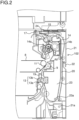
- Fig. 2 is a part sectional view around the sheet conveyance passage 19 and the duplex conveyance passage 20 in the image forming apparatus 100 according to this embodiment.
- An open/close cover 21 constitutes part of a side face 102 of the image forming apparatus 100 and is pivotably supported on a cover shaft 21a provided in the lower part of the main body of the image forming apparatus 100.
- the inner side face of the open/close cover 21 constitutes part of one (outside) of the conveyance faces of the duplex conveyance passage 20.
- the side face of the open/close cover 21 is provided with a grip portion 22.
- the grip portion 22 keeps the open/close cover 21 closed with one end part of the grip portion 22 engaging with engagement pins (not illustrated) provided on a front frame and a rear frame of the main body of the image forming apparatus 100. To open the open/closed cover 21, the grip portion 22 is pivoted to disengage from the engagement pins.
- a conveyance unit 23 Inward of the open/close cover 21 is arranged a conveyance unit 23.
- the conveyance unit 23 is supported on the main body of the image forming apparatus 100 so as to be pivotable about a unit shaft 23a and the conveyance unit 23 constitutes part of the conveyance face of the duplex conveyance passage 20 and the sheet conveyance passage 19.
- the duplex conveyance passage 20 extends between the inner side surface of the open/close cover 21 and the outer side surface of the conveyance unit 23 along the side face 102 of the image forming apparatus 100 in the up-down direction, then curves substantially in a C-shape to join the sheet conveyance passage 19.
- the inner side surface of the conveyance unit 23 is fitted with, in order from upstream (bottom in Fig. 2 ) in the conveyance direction of the transfer sheet P, a one-side roller 13b, which together with a main-body-side roller 13a constitutes the pair of registration rollers 13, and the secondary transfer roller 9.
- the duplex conveyance passage 20 is exposed over a wide range.
- the conveyance unit 23 moves away from the main body of the image forming apparatus 100 and the sheet conveyance passage 19 is exposed over a wide range.
- the conveyance unit 23 makes contact with the main body of the image forming apparatus 100, the secondary transfer roller 9 is pressed against the driving roller 11 with the intermediate transfer belt 8 in between to form a secondary transfer nip N1.
- Fig. 3 is a perspective view, as seen from the downstream side (left side in Fig. 2 ) in the discharging direction of the transfer sheet P from the image forming apparatus 100, of the fixing device 14.
- Fig. 4 is a side sectional view of the fixing device 14 as cut at its middle in the longitudinal direction.
- the fixing device 14 has a housing 30, side covers 31a and 31b, and a stay 31c.
- the housing 30 houses the fixing belt 14a and the pressing roller 14b.
- Above the housing 30 is supported one-side (left side in Fig. 2 ) roller 24a constituting the pair of fixing discharge rollers 24.
- the side covers 31a and 31b are fixed to side plates 30a and 30b arranged at the opposite ends of the housing 30 in the longitudinal direction.
- the stay 31c is made of metal and is a plate-form member fixed to the housing 30 along the longitudinal direction.
- a pair of spring brackets 40 are formed, each to support one end (lower end) of a pressing spring 35 (see Fig. 5 ) of a pressing mechanism 32.
- a driving input gear 60 and a depressurizing gear 61 are arranged at the side cover 31a side.
- the driving input gear 60 meshes with a roller driving gear 142 (see Fig. 5 ) fixed to a rotation shaft 141 of the pressing roller 14b.
- a rotational driving force is transmitted from a fixing driving motor (not illustrated) via a driving output gear 80 (see Fig. 13 ) on the main body of the image forming apparatus 100 to the driving input gear 60
- the pressing roller 14b rotates at a predetermined speed.
- the fixing belt 14a kept in pressed contact with the fixing roller 14b also rotates by following the pressing roller 14b.
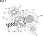
- Fig. 5 is a side view showing the configuration around the pressing mechanism 32 in the fixing device 14.
- the roller driving gear 142 On the shaft 141 of the pressing roller 14b, the roller driving gear 142 is fixed.
- the roller driving gear 142 is coupled with the driving input gear 60.
- a nip forming member 41 Inside the fixing belt 14a are arranged a nip forming member 41 and a belt guide 42.
- the nip forming member 41 makes contact with the pressing roller 14b via the fixing belt 14a to form a fixing nip portion N2 through which the transfer sheet P is inserted.
- the nip forming member 41 is made of a heat-resistant resin such as a liquid crystal polymer or an elastic material such as silicone rubber and an elastomer may be arranged on the surface facing the fixing belt 14a for enhanced sliding properties.
- the belt guide 42 is in the shape of an arc in a sectional view and makes contact with the inner circumferential surface of the fixing belt 14a except on the surface facing the nip forming member 41.
- the belt guide 42 applies a predetermined tension to the fixing belt 14a and holds the fixing belt 14a in the shape of an arc from inside it.
- the belt guide 42 is formed of a metal plate that extends along the axial direction of the fixing belt 14a over substantially the same length as the fixing belt 14a.
- a pair of pressing mechanisms 32 are provided at the opposite ends of the fixing belt 14a and the pressing roller 14b in the axial direction.
- Each pressing mechanism 32 has a pressing plate 33, a pressing spring 35, and an eccentric cam 37.
- the pressing plate 33 is arranged opposite a belt holder 143 that supports the opposite ends of the fixing belt 14a, the nip forming member 41, and the belt guide 42 in the longitudinal direction.
- the pressing plate 33 has a fulcrum portion 33a supported on the housing 30 (see Fig. 3 ) of the fixing device 13 and is swingable in directions toward and away from the belt holder 143.
- the pressing spring 35 urges the belt holder 143 in a direction toward the pressing roller 14b. Specifically, one end of the pressing spring 35 is supported in the spring bracket 40
- the other end of the pressing spring 35 is fitted around a boss (not illustrated) on the belt holder 143 that projects through a through-hole 33b formed in the pressing plate 33 and is in contact with the pressing plate 33.
- the inner diameter of the through-hole 33b is smaller than the outer diameter of the pressing spring 35 and as the pressing plate 33 swings, the pressing spring 35 stretch and contracts between the pressing plate 33 and the spring bracket 40.
- the eccentric cam 37 is arranged at the same side (right side in Fig. 5 ) as the belt holder 143 with respect to the pressing plate 33.
- the eccentric cam 37 is formed integrally with the depressurizing gear 61 that feeds the driving force to the pressing mechanism 32. As the eccentric cam 37 rotates together with the depressurizing gear 61, a change occurs in the outer diameter of the eccentric cam 37 that makes contact with the pressing plate 33.
- Figs. 6 and 7 are side views showing a pressurized state and a depressurized state, respectively, of the pressing mechanism 32.
- the urging force of the pressing spring 35 causes a constant pressure to act on the belt holder 143.
- the pressing roller 14b is kept in pressed contact with the nip forming member 41 to form the fixing nip N2 (see Fig. 5 ) with the fixing belt 14a.
- a light-shielding portion 33c formed on the swinging end of the pressing plate 33 is retracted from a sensing portion of a PI sensor 70 and the PI sensor 70 senses the pressurized state.
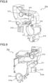
- Figs. 8 and 9 are perspective views, as seen from inside and outside respectively, of the side cover 31a of the fixing device 14.
- the side cover 31a is mounted on one end side (left side in Fig. 3 ) of the housing 30 and constitutes part of the exterior surface of the fixing device 14.
- a first bearing portion 311, a second bearing portion 312, a third bearing portion 313, a gear cover portion 314, and a positioning pin 315 In the side cover 31a are formed a first bearing portion 311, a second bearing portion 312, a third bearing portion 313, a gear cover portion 314, and a positioning pin 315.
- the first bearing portion 311 is a circular through-hole in which is inserted a drive transmission shaft 61a (see Fig. 10 ) of the depressurizing gear 61 in the pressing mechanism 32.
- the inner diameter of the first bearing portion 311 is slightly larger than the diameter of the drive transmission shaft 61a.
- the first bearing portion 311 rotatably supports the drive transmission shaft 61a and positions the drive transmission shaft 61a.
- the second bearing portion 312 is a U-shaped groove with a cutout portion 312a formed in part of the circumference of a through-hole in a cylindrical shape.
- a rotation shaft 81a (see Fig. 12 ) of a depressurizing input gear 81 on the main body of the image forming apparatus 100.
- the second bearing portion 312 rotatably supports the rotation shaft 81a and positions the rotating shaft 81a.
- the third bearing portion 313 is a circular through-hole in which is inserted a coupling (not illustrated) that drives the roller 24a (see Fig. 3 ) constituting the pair of fixing discharge rollers 24.
- the third bearing portion 313 rotatably supports the coupling that drives the roller 24a and also positions the coupling.
- the gear cover portion 314 is in a cylindrical shape and covers the driving input gear 60 (see Fig. 5 ) from outside.
- the inner diameter of the gear cover portion 314 is slightly larger than the diameter of the driving input gear 60.
- In the gear cover portion 314 is formed a circular opening 314a.
- the side face (coupling face) of the driving input gear 60 is exposed through the opening 314a to allow the driving input gear 60 to be coupled to the driving output gear 80 (see Fig. 13 ) on the main body of the image forming apparatus 100.
- the positioning pin 315 is inserted into a positioning hole (not illustrated) in the side plate 30a (see Fig. 3 ) of the housing 30 when the side cover 31a is fitted to the housing 30. This positions the side cover 31a relative to the side plate 30a.
- Fig. 10 is a perspective view showing a state in which the side cover 31a is fitted to the housing 30 of the fixing device 14.
- Fig. 11 is a diagram showing a state in which, from the state shown in Fig. 10 , the depressurizing gear 61 is fitted to the drive transmission shaft 61a.
- the drive transmission shaft 61a is inserted into the first bearing portion 311, the driving input gear 60 is inserted into the gear cover portion 314, and the positioning pin 315 (see Fig. 8 ) formed on the inner face of the side cover 31a is inserted into the positioning hole (not illustrated) formed in the side plate 30a of the housing 30.
- the driving transmission shaft 61a has a D-cut shaped section and supports the depressurizing gear 61 such that this is movable in the thrust direction but not rotatable in the circumferential direction.
- the depressurizing gear 61 is coupled with the depressurizing gear 61 at the other side (side cover 31b side) by the driving transmission shaft 61a.
- a rotational driving force fed from the depressurizing input gear 81 to the depressurizing gear 61 is transmitted via the drive transmission shaft 61a to the depressurizing gear 61 and the eccentric cam 37 at the other side.
- the gear cover portion 314 in the side cover 31a and the driving input gear 60 in the housing 30 are positioned with each other and the driving input gear 60 is housed in the gear cover portion 314.
- the input coupling teeth 60a are exposed through the opening 314a in the gear cover portion 314.
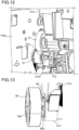
- Fig. 12 is a perspective view showing a state in which the depressurizing gear 61 and the depressurizing input gear 81 are coupled together.
- On a side frame 100a of the image forming apparatus 100 facing the side cover 31a are arranged the driving output gear 80 (see Fig. 13 ) and the depressurizing input gear 81.
- the open/close cover 21 (see Fig. 2 ) on the image forming apparatus 100 is opened and the fixing device 14 is inserted in the horizontal direction (from right to left in Fig. 2 ).
- the rotation shaft 81a of the depressurizing input gear 81 is inserted into the second bearing portion 312 in the side cover 31a. More specifically, through the cutout portion 312a in the second bearing portion 312, which has a U-shaped groove, the rotation shaft 81a is radially inserted.
- the depressurizing input gear 81 is positioned relative to the side cover 31a.
- the driving transmission shaft 61a ( Fig. 10 ) of the depressurizing gear 61 is inserted in the first bearing portion 311, so the depressurizing gear 61 is also positioned relative to the side cover 31a. That is, both the depressurizing gear 61 and the depressurizing input gear 81 are positioned relative to the side cover 31a.
- Fig. 13 is a perspective view showing a state in which the driving input gear 60 and the driving output gear 80 are coupled together.
- the driving output gear 80 is arranged on the side frame 100a (see Fig. 12 ).
- output coupling teeth 80a are formed on the side face of the driving output gear 80 (the face facing the driving input gear 60).
- the driving output gear 80 is movable in the thrust direction relative to the side frame 100a and is urged inward of the side frame 100a with a spring (not illustrated).
- the driving output gear 80 faces the driving input gear 60 on the fixing device 14. Then, as shown in Fig. 13 , the output coupling teeth 80a on the driving input gear 80 and the input coupling teeth 60a on the driving input gear 60 mesh with each other in the thrust direction to transmit a rotational driving force from the driving output gear 80 to the driving input gear 60.
- the positioning accuracy between the depressurizing gear 61 on the fixing device 14 and the depressurizing input gear 81 on the main body of the image forming apparatus 100 is improved and the inter-axial distance (gear pitch) is kept constant; this helps prevent meshing failure (tooth skipping) on the depressurizing gear 61 and the depressurizing input gear 81 and prevent abnormal noise.
- the depressurizing gear 61 and the depressurizing input gear 81 can be positioned relative to each other, and this helps reduce the number of the components of the fixing device 14. It is thus possible to reduce the size and the weight of the fixing device 14.
- Fig. 14 is a side sectional view showing a state in which the driving input gear 60 and the roller driving gear 142 are coupled together.
- gear teeth 60b On the outer circumferential surface of the driving input gear 60 are formed gear teeth 60b that mesh with the roller driving gear 142.
- a ring-shaped flange portion 60c Between the input coupling teeth 60a and the gear teeth 60b is formed a ring-shaped flange portion 60c.
- the gear cover portion 314 holds the driving input gear 60 with the circumferential edge of the opening 314a engaging with the flange portion 60c.
- the gear cover portion 314 of the side cover 31a positions the driving input gear 60; thus, through the engagement of the second bearing portion 312 with the rotation shaft 81a of the depressurizing input gear 81, the driving input gear 60 on the fixing device 14 and the driving output gear 80 on the main body of the image forming device 100 are also positioned indirectly with the side cover 31a. As a result, the positioning accuracy of the driving input gear 60 and the driving output gear 80 is also improved.
- the shaft 60d of the driving input gear 60 has a long protruding length relative to the housing 30 and so is prone to axis inclination.
- the gear cover portion 314 holding the driving input gear 60 also helps prevent axis inclination of the shaft 60d.
- the present disclosure is not limited to the above embodiment and can be carried out with any modifications made without departure from the spirit of the present disclosure.
- the above embodiment takes up as an example a belt heating-type fixing device 14 that includes an endless fixing belt 14a as a heated rotating member
- the present disclosure is applicable also to fixing devices including a heated rotating member other than a fixing belt 14a, such as a fixing roller.
- a color printer as shown in Fig. 1
- the present disclosure is applicable not only to color printers but also to any image forming apparatuses including a fixing device, such as color copiers, color multifunction peripherals, monochrome printers, and monochrome copiers.
- the present disclosure finds applications in fixing devices incorporated in image forming apparatuses such as copiers, printers, facsimile machines, and multifunction peripherals having their functions integrated together. Based on the present disclosure, it is possible to enhance the positioning accuracy of a driving member with a simple configuration and to provide a fixing device that can prevent problems such as coupling failure and abnormal noise caused by displacement of a coupling portion, and to provide an image forming apparatus provided with such a fixing device.
Landscapes
- Physics & Mathematics (AREA)
- General Physics & Mathematics (AREA)
- Fixing For Electrophotography (AREA)
- Electrophotography Configuration And Component (AREA)
Abstract
A fixing device (14) includes a fixing member (14a, 14b), a housing (30) that houses the fixing member (14a, 14b), a side cover (31a, 31b), a pressing mechanism (32), and a unit side gear (60, 61), and fuses and fixes an unfixed toner image on a sheet passing through a fixing nip (N2). The fixing member (14a, 14b) has a heated rotating member (14a) and a pressing rotating member (14b) kept in pressed contact with the heated rotating member (14a) to form the fixing nip (N2). The side cover (31a, 31b) is fitted to at least one longitudinal end of the housing (30). The pressing mechanism (32) adjusts pressure between the heated rotating member (14a) and the pressing rotating member (14b). The unit side gear (60, 61) is coupled with a main body side gear (80, 81) provided on a main body of an image forming apparatus (100), and transmits a driving force to the fixing member (14a, 14b) or the pressing mechanism (32). The side cover (31a) has a first positioning portion (311, 314) that positions the unit side gear (60, 61) and a second positioning portion (312, 314) that positions the main body side gear (80, 81).
Description
- The present disclosure relates to fixing devices incorporated in image forming apparatuses such as multifunction peripherals, printers, facsimile machines, and multifunction peripherals having their functions integrated together, and to image forming apparatuses provided with such a fixing device.
- In electrophotographic type image forming apparatuses, to fix a toner image to a sheet, wide use is made of a fixing device including a fixing member configured with a fixing roller or a fixing belt (a heated rotating member) and a pressing roller (a pressing rotating member) kept in pressed contact with each other. This fixing device passes the sheet through a fixing nip portion formed between the fixing roller or the fixing belt and the pressing roller, and heats and presses the toner image to fuse and fix the toner image to the sheet.
- With the fixing device described above, the heated rotating member and the pressing rotating member are kept in pressed contact with each other, and this necessitates a configuration that can relieve the pressure for removal of the sheet when a jam occurs.
- An object of the present disclosure is to enhance the positioning accuracy of a driving member with a simple configuration and to provide a fixing device that can prevent problems such as coupling failure and abnormal noise caused by displacement of a coupling portion, and to provide an image forming apparatus provided with such a fixing device.
- According to one aspect of the present disclosure, a fixing device includes a fixing member, a housing, a side cover, a pressing mechanism, and a unit side gear, and heats and presses a sheet passing through a fixing nip portion to fuse and fix an unfixed toner image on the sheet. The fixing member is configured with a heated rotating member and a pressing rotating member kept in pressed contact with the heated rotating member to form the fixing nip portion. The housing houses the fixing member. The side cover is fitted to at least one end of the housing in the longitudinal direction. The pressing mechanism adjusts the pressure between the heated rotating member and the pressing rotating member. The unit side gear is coupled with a main body side gear provided on a main body of an image forming apparatus, and transmits a driving force to the fixing member or the pressing mechanism. The side cover has a first positioning portion that positions the unit side gear and a second positioning portion that positions the main body side gear.
-
-
Fig. 1 is a schematic sectional view showing the overall construction of animage forming apparatus 100 according to an embodiment of the present disclosure. -
Fig. 2 is a part sectional view around asheet conveyance passage 19 and aduplex conveyance passage 20 in theimage forming apparatus 100 according to the embodiment. -
Fig. 3 is a perspective view of afixing device 14 as seen from downstream in the discharging direction of a transfer sheet P from theimage forming apparatus 100. -
Fig. 4 is a side sectional view of thefixing device 14 as cut at its middle in the longitudinal direction. -
Fig. 5 is a side sectional view showing the configuration around apressing mechanism 32 in thefixing device 14. -
Fig. 6 is a side view showing a state pressurize by thepressing mechanism 32. -
Fig. 7 is a side view showing a state depressurized by thepressing mechanism 32. -
Fig. 8 is a perspective view, as seen from inside, of aside cover 31a of thefixing device 14. -
Fig. 9 is a perspective view, as seen from outside, of theside cover 31a of thefixing device 14. -
Fig. 10 is a perspective view showing a state in which theside cover 31a is fitted to ahousing 30 of thefixing device 14. -
Fig. 11 is a diagram showing a state in which, from the state shown inFig. 10 , a depressurizinggear 61 is fitted to adrive transmission shaft 61a. -
Fig. 12 is a perspective view showing a state in which thedepressurizing gear 61 and a depressurizinginput gear 81 are coupled together. -
Fig. 13 is a perspective view showing a state in which adriving input gear 60 and adriving output gear 80 are coupled together. -
Fig. 14 is a side sectional view showing a state in which thedriving input gear 60 and aroller driving gear 142 are coupled together. - Hereinafter, an embodiment of the present disclosure will be described with reference to the drawings.
Fig. 1 is a sectional view showing the internal construction of animage forming apparatus 100 according to an embodiment of the present disclosure. In a main body of the image forming apparatus 100 (here, a color printer), four image forming portions Pa, Pb, Pc, and Pd are arranged in this order from upstream (the left side inFig. 1 ) in the conveyance direction. The image forming portions Pa to Pd are provided so as to correspond to images of four different colors (yellow, cyan, magenta, and black). The image forming portions Pa to Pd form yellow, cyan, magenta, and black images sequentially, each through the processes of electrostatic charging, exposure to light, image development, and image transfer. - In these image forming portions Pa to Pd are arranged photosensitive drums (image carrying member) 1a, 1b, 1c, and 1d, which carry visible images (toner images) of the different colors. An intermediate transfer belt (intermediate transfer member) 8 that rotates counterclockwise in
Fig. 1 by being driven by a belt driving motor (not illustrated) is provided adjacent to the image forming portions Pa to Pd. The toner images formed on thephotosensitive drums 1a to 1d are, by being primarily transferred sequentially to theintermediate transfer belt 8, which moves while in contact with thephotosensitive drums 1a to 1d, overlaid on each other. Thereafter, the toner images primarily transferred to theintermediate transfer belt 8 are secondarily transferred by asecondary transfer roller 9 to a transfer sheet P as one example of a recording medium. The transfer sheet P having the toner images secondarily transferred to it then has the toner images fixed to it in afixing device 14 and is then discharged out of the main body of theimage forming apparatus 100. While thephotosensitive drums 1a to 1d are rotated clockwise inFig. 1 , an image forming process is performed with respect to thephotosensitive drums 1a to 1d. - The transfer sheets P to which toner images will be secondarily transferred are stored inside a
sheet cassette 16 arranged in a lower part of the main body of theimage forming apparatus 100. The transfer sheet P is conveyed via asheet feed roller 12 and a pair ofregistration rollers 13 along asheet conveyance passage 19 to the nip between thesecondary transfer roller 9 and adriving roller 11 for theintermediate transfer belt 8. Used as theintermediate transfer belt 8 is a sheet of a dielectric resin, typically a belt with no seam (a seamless belt). Downstream of thesecondary transfer roller 9, a blade-form belt cleaner 25 for removing toner and the like left on the surface of theintermediate transfer belt 8 is provided. - Next, the image forming portions Pa to Pd will be described. Around and under the
photosensitive drums 1a to 1d, which are rotatably arranged, there are providedcharging devices photosensitive drums 1a to 1d, anexposure device 5 which exposes thephotosensitive drums 1a to 1d to light conveying image information, developing device 3a, 3b, 3c, and 3d which form toner images on thephotosensitive drums 1a to 1d, and cleaningdevices photosensitive drums 1a to 1d. - When image data is fed in from a host device such as a personal computer, first, the
charging devices 2a to 2d electrostatically charge the surfaces of thephotosensitive drums 1a to 1d uniformly. Next, theexposure device 5 irradiates thephotosensitive drums 1a to 1d with light according to image data to form on them electrostatic latent images according to the image data. The development devices 3a to 3d are loaded with predetermined amounts of two-component developer containing toner of different colors, namely yellow, cyan, magenta, and black respectively. When, as image formation proceeds as will be described later, the proportion of the toner in the two-component developer in the development devices 3a to 3d falls below a prescribed value, toner is supplied fromtoner containers 4a to 4d to the development devices 3a to 3d. The toner in the developer is fed from the development devices 3a to 3d to thephotosensitive drums 1a to 1d and electrostatically adhere to them. Thus, toner images are formed according to the electrostatic latent images formed by exposure to light from theexposure device 5. - Then, primary transfer rollers 6a to 6d apply an electric field at a predetermined transfer voltage between the primary transfer rollers 6a to 6d and the
photosensitive drums 1a to 1d, and thereby the yellow, cyan, magenta, and black toner images on thephotosensitive drums 1a to 1d are primarily transferred to theintermediate transfer belt 8. These images are formed with a predetermined positional relationship. After that, in preparation for the subsequent formation of new electrostatic latent images, the toner and the like remaining on the surfaces ofphotosensitive drums 1a to 1d after primary transfer are removed by cleaningdevices 7a to 7d. - The
intermediate transfer belt 8 is wound around a drivenroller 10, arranged upstream, and thedriving roller 11, arranged downstream. As thedriving roller 11 is rotated by the belt driving motor (not illustrated), theintermediate transfer belt 8 starts rotating counterclockwise, and the transfer sheet P is conveyed with predetermined timing from the pair ofregistration rollers 13 to a secondary transfer nip portion N1 (seeFig. 2 ) between thedriving roller 11 and thesecondary transfer roller 9 provided next to it. The toner images formed on theintermediate transfer belt 8 are secondarily transferred to the transfer sheet P passing through the secondary transfer nip portion N1. - The transfer sheet P having the toner images secondarily transferred to it is conveyed to the
fixing device 14. Thefixing device 14 has afixing belt 14a and apressing roller 14b (seeFig. 2 for both). Thefixing belt 14a is heated with a heater (not illustrated). The pressingroller 14b is kept in pressed contact with thefixing belt 14a to form a fixing nip N2 (seeFig. 5 ) and applies a rotational driving force to thefixing belt 14a. Instead of the heater, an induction heating portion may be provided on the outside of thefixing belt 14a. - The transfer sheet P conveyed to the
fixing portion 14 is heated and pressed by thefixing belt 14a and thepressing roller 14b; thus the toner images are fixed to the surface of the transfer sheet P and a predetermined full-color image is formed. The transfer sheet P with the full-color image formed on it is conveyed via a pair of fixing discharge rollers 24 (seeFig. 2 ) and then has its conveyance direction switched by abranch portion 15 that branches into a plurality of directions so as to be discharged as it is (or after being diverted to aduplex conveyance passage 20 to have images formed on both sides) to adischarge tray 18 by a pair ofdischarge rollers 17. -
Fig. 2 is a part sectional view around thesheet conveyance passage 19 and theduplex conveyance passage 20 in theimage forming apparatus 100 according to this embodiment. An open/close cover 21 constitutes part of aside face 102 of theimage forming apparatus 100 and is pivotably supported on acover shaft 21a provided in the lower part of the main body of theimage forming apparatus 100. The inner side face of the open/close cover 21 constitutes part of one (outside) of the conveyance faces of theduplex conveyance passage 20. - The side face of the open/
close cover 21 is provided with agrip portion 22. Thegrip portion 22 keeps the open/close cover 21 closed with one end part of thegrip portion 22 engaging with engagement pins (not illustrated) provided on a front frame and a rear frame of the main body of theimage forming apparatus 100. To open the open/closed cover 21, thegrip portion 22 is pivoted to disengage from the engagement pins. - Inward of the open/
close cover 21 is arranged aconveyance unit 23. Theconveyance unit 23 is supported on the main body of theimage forming apparatus 100 so as to be pivotable about aunit shaft 23a and theconveyance unit 23 constitutes part of the conveyance face of theduplex conveyance passage 20 and thesheet conveyance passage 19. Theduplex conveyance passage 20 extends between the inner side surface of the open/close cover 21 and the outer side surface of theconveyance unit 23 along theside face 102 of theimage forming apparatus 100 in the up-down direction, then curves substantially in a C-shape to join thesheet conveyance passage 19. The inner side surface of theconveyance unit 23 is fitted with, in order from upstream (bottom inFig. 2 ) in the conveyance direction of the transfer sheet P, a one-side roller 13b, which together with a main-body-side roller 13a constitutes the pair ofregistration rollers 13, and thesecondary transfer roller 9. - As the open/
close cover 21 alone is pivoted to open in the opening direction with respect to theimage forming apparatus 100, theduplex conveyance passage 20 is exposed over a wide range. As the open/close cover 21 is pivoted together with theconveyance unit 23 in the opening direction, theconveyance unit 23 moves away from the main body of theimage forming apparatus 100 and thesheet conveyance passage 19 is exposed over a wide range. By contrast, as the open/close cover 21 is pivoted together with theconveyance unit 23 to close in the closing direction, theconveyance unit 23 makes contact with the main body of theimage forming apparatus 100, thesecondary transfer roller 9 is pressed against the drivingroller 11 with theintermediate transfer belt 8 in between to form a secondary transfer nip N1. - Next, the configuration of the fixing
device 14 will be described.Fig. 3 is a perspective view, as seen from the downstream side (left side inFig. 2 ) in the discharging direction of the transfer sheet P from theimage forming apparatus 100, of the fixingdevice 14.Fig. 4 is a side sectional view of the fixingdevice 14 as cut at its middle in the longitudinal direction. - The fixing
device 14 has ahousing 30, side covers 31a and 31b, and astay 31c. Thehousing 30 houses the fixingbelt 14a and thepressing roller 14b. Above thehousing 30 is supported one-side (left side inFig. 2 )roller 24a constituting the pair of fixingdischarge rollers 24. - The side covers 31a and 31b are fixed to
side plates housing 30 in the longitudinal direction. Thestay 31c is made of metal and is a plate-form member fixed to thehousing 30 along the longitudinal direction. At the opposite ends of thestay 31c in the longitudinal direction, a pair ofspring brackets 40 are formed, each to support one end (lower end) of a pressing spring 35 (seeFig. 5 ) of apressing mechanism 32. - At the
side cover 31a side are arranged a drivinginput gear 60 and adepressurizing gear 61. The drivinginput gear 60 meshes with a roller driving gear 142 (seeFig. 5 ) fixed to arotation shaft 141 of thepressing roller 14b. When a rotational driving force is transmitted from a fixing driving motor (not illustrated) via a driving output gear 80 (seeFig. 13 ) on the main body of theimage forming apparatus 100 to the drivinginput gear 60, thepressing roller 14b rotates at a predetermined speed. Thus, the fixingbelt 14a kept in pressed contact with the fixingroller 14b also rotates by following thepressing roller 14b. -
Fig. 5 is a side view showing the configuration around thepressing mechanism 32 in the fixingdevice 14. On theshaft 141 of thepressing roller 14b, theroller driving gear 142 is fixed. Theroller driving gear 142 is coupled with the drivinginput gear 60. - Inside the fixing
belt 14a are arranged anip forming member 41 and abelt guide 42. Thenip forming member 41 makes contact with thepressing roller 14b via the fixingbelt 14a to form a fixing nip portion N2 through which the transfer sheet P is inserted. Thenip forming member 41 is made of a heat-resistant resin such as a liquid crystal polymer or an elastic material such as silicone rubber and an elastomer may be arranged on the surface facing the fixingbelt 14a for enhanced sliding properties. - The
belt guide 42 is in the shape of an arc in a sectional view and makes contact with the inner circumferential surface of the fixingbelt 14a except on the surface facing thenip forming member 41. Thebelt guide 42 applies a predetermined tension to the fixingbelt 14a and holds the fixingbelt 14a in the shape of an arc from inside it. Thebelt guide 42 is formed of a metal plate that extends along the axial direction of the fixingbelt 14a over substantially the same length as the fixingbelt 14a. - A pair of
pressing mechanisms 32 are provided at the opposite ends of the fixingbelt 14a and thepressing roller 14b in the axial direction. Eachpressing mechanism 32 has apressing plate 33, apressing spring 35, and aneccentric cam 37. - The
pressing plate 33 is arranged opposite abelt holder 143 that supports the opposite ends of the fixingbelt 14a, thenip forming member 41, and thebelt guide 42 in the longitudinal direction. Thepressing plate 33 has afulcrum portion 33a supported on the housing 30 (seeFig. 3 ) of the fixingdevice 13 and is swingable in directions toward and away from thebelt holder 143. - The
pressing spring 35 urges thebelt holder 143 in a direction toward thepressing roller 14b. Specifically, one end of thepressing spring 35 is supported in thespring bracket 40 - (see
Fig. 3 ) formed in thestay 31c. The other end of thepressing spring 35 is fitted around a boss (not illustrated) on thebelt holder 143 that projects through a through-hole 33b formed in thepressing plate 33 and is in contact with thepressing plate 33. The inner diameter of the through-hole 33b is smaller than the outer diameter of thepressing spring 35 and as thepressing plate 33 swings, thepressing spring 35 stretch and contracts between thepressing plate 33 and thespring bracket 40. - The
eccentric cam 37 is arranged at the same side (right side inFig. 5 ) as thebelt holder 143 with respect to thepressing plate 33. Theeccentric cam 37 is formed integrally with thedepressurizing gear 61 that feeds the driving force to thepressing mechanism 32. As theeccentric cam 37 rotates together with thedepressurizing gear 61, a change occurs in the outer diameter of theeccentric cam 37 that makes contact with thepressing plate 33. -
Figs. 6 and 7 are side views showing a pressurized state and a depressurized state, respectively, of thepressing mechanism 32. As shown inFig. 6 , when a small-diameter portion of theeccentric cam 37 faces thepressing plate 33, the urging force of thepressing spring 35 causes a constant pressure to act on thebelt holder 143. Thus, thepressing roller 14b is kept in pressed contact with thenip forming member 41 to form the fixing nip N2 (seeFig. 5 ) with the fixingbelt 14a. In the state inFig. 6 , a light-shieldingportion 33c formed on the swinging end of thepressing plate 33 is retracted from a sensing portion of aPI sensor 70 and thePI sensor 70 senses the pressurized state. - When the
eccentric cam 37 rotates a predetermined amount from the state inFig. 6 and, as shown inFig.7 , a large-diameter portion of theeccentric cam 37 makes contact with thepressing plate 33, thepressing plate 33 is pressed against the urging force of thepressing spring 35 in a direction away from thebelt holder 143. As a result, thepressing spring 35 is compressed between thepressing plate 33 and thespring bracket 40 and the pressure acting from thepressing plate 33 to thebelt holder 143 is weakened. In the state inFig. 7 , the light-shieldingportion 33c shields from light the sensing portion of thePI sensor 70 and thePI sensor 70 senses the depressurized state. -
Figs. 8 and 9 are perspective views, as seen from inside and outside respectively, of theside cover 31a of the fixingdevice 14. Theside cover 31a is mounted on one end side (left side inFig. 3 ) of thehousing 30 and constitutes part of the exterior surface of the fixingdevice 14. In theside cover 31a are formed afirst bearing portion 311, asecond bearing portion 312, athird bearing portion 313, agear cover portion 314, and apositioning pin 315. - The
first bearing portion 311 is a circular through-hole in which is inserted adrive transmission shaft 61a (seeFig. 10 ) of thedepressurizing gear 61 in thepressing mechanism 32. The inner diameter of thefirst bearing portion 311 is slightly larger than the diameter of thedrive transmission shaft 61a. Thefirst bearing portion 311 rotatably supports thedrive transmission shaft 61a and positions thedrive transmission shaft 61a. - The
second bearing portion 312 is a U-shaped groove with acutout portion 312a formed in part of the circumference of a through-hole in a cylindrical shape. In thesecond bearing portion 312 is inserted arotation shaft 81a (seeFig. 12 ) of a depressurizinginput gear 81 on the main body of theimage forming apparatus 100. Thesecond bearing portion 312 rotatably supports therotation shaft 81a and positions therotating shaft 81a. - The
third bearing portion 313 is a circular through-hole in which is inserted a coupling (not illustrated) that drives theroller 24a (seeFig. 3 ) constituting the pair of fixingdischarge rollers 24. Thethird bearing portion 313 rotatably supports the coupling that drives theroller 24a and also positions the coupling. - The
gear cover portion 314 is in a cylindrical shape and covers the driving input gear 60 (seeFig. 5 ) from outside. The inner diameter of thegear cover portion 314 is slightly larger than the diameter of the drivinginput gear 60. In thegear cover portion 314 is formed acircular opening 314a. The side face (coupling face) of the drivinginput gear 60 is exposed through theopening 314a to allow the drivinginput gear 60 to be coupled to the driving output gear 80 (seeFig. 13 ) on the main body of theimage forming apparatus 100. - The
positioning pin 315 is inserted into a positioning hole (not illustrated) in theside plate 30a (seeFig. 3 ) of thehousing 30 when theside cover 31a is fitted to thehousing 30. This positions theside cover 31a relative to theside plate 30a. -
Fig. 10 is a perspective view showing a state in which theside cover 31a is fitted to thehousing 30 of the fixingdevice 14.Fig. 11 is a diagram showing a state in which, from the state shown inFig. 10 , the depressurizinggear 61 is fitted to thedrive transmission shaft 61a. When theside cover 31a is fitted to thehousing 30, thedrive transmission shaft 61a is inserted into thefirst bearing portion 311, the drivinginput gear 60 is inserted into thegear cover portion 314, and the positioning pin 315 (seeFig. 8 ) formed on the inner face of theside cover 31a is inserted into the positioning hole (not illustrated) formed in theside plate 30a of thehousing 30. - Thus, the
first bearing portion 311 in theside cover 31a and the drivingtransmission shaft 61a on thehousing 30 are positioned with each other. The drivingtransmission shaft 61a has a D-cut shaped section and supports thedepressurizing gear 61 such that this is movable in the thrust direction but not rotatable in the circumferential direction. - The depressurizing
gear 61 is coupled with thedepressurizing gear 61 at the other side (side cover 31b side) by the drivingtransmission shaft 61a. A rotational driving force fed from the depressurizinginput gear 81 to thedepressurizing gear 61 is transmitted via thedrive transmission shaft 61a to thedepressurizing gear 61 and theeccentric cam 37 at the other side. - The
gear cover portion 314 in theside cover 31a and the drivinginput gear 60 in thehousing 30 are positioned with each other and the drivinginput gear 60 is housed in thegear cover portion 314. On the side face of the driving input gear 60 (the face facing the driving output gear 80)input coupling teeth 60a are formed. Theinput coupling teeth 60a are exposed through theopening 314a in thegear cover portion 314. -
Fig. 12 is a perspective view showing a state in which thedepressurizing gear 61 and the depressurizinginput gear 81 are coupled together. On aside frame 100a of theimage forming apparatus 100 facing theside cover 31a are arranged the driving output gear 80 (seeFig. 13 ) and the depressurizinginput gear 81. - When the fixing
device 14 is mounted in the main body of theimage forming apparatus 100, the open/close cover 21 (seeFig. 2 ) on theimage forming apparatus 100 is opened and the fixingdevice 14 is inserted in the horizontal direction (from right to left inFig. 2 ). - As the fixing
device 14 is inserted, as shown inFig. 12 , therotation shaft 81a of the depressurizinginput gear 81 is inserted into thesecond bearing portion 312 in theside cover 31a. More specifically, through thecutout portion 312a in thesecond bearing portion 312, which has a U-shaped groove, therotation shaft 81a is radially inserted. Thus, the depressurizinginput gear 81 is positioned relative to theside cover 31a. The drivingtransmission shaft 61a (Fig. 10 ) of thedepressurizing gear 61 is inserted in thefirst bearing portion 311, so the depressurizinggear 61 is also positioned relative to theside cover 31a. That is, both thedepressurizing gear 61 and the depressurizinginput gear 81 are positioned relative to theside cover 31a. -
Fig. 13 is a perspective view showing a state in which the drivinginput gear 60 and the drivingoutput gear 80 are coupled together. As shown inFig. 13 , on theside frame 100a (seeFig. 12 ), the drivingoutput gear 80 is arranged. On the side face of the driving output gear 80 (the face facing the driving input gear 60),output coupling teeth 80a are formed. The drivingoutput gear 80 is movable in the thrust direction relative to theside frame 100a and is urged inward of theside frame 100a with a spring (not illustrated). - As shown in
Fig. 12 , when theside cover 31a is placed so as to face theside frame 100a and thedepressurizing gear 61 and the depressurizinginput gear 81 are coupled together, the drivingoutput gear 80 faces the drivinginput gear 60 on the fixingdevice 14. Then, as shown inFig. 13 , theoutput coupling teeth 80a on the drivinginput gear 80 and theinput coupling teeth 60a on the drivinginput gear 60 mesh with each other in the thrust direction to transmit a rotational driving force from the drivingoutput gear 80 to the drivinginput gear 60. - With the configuration described above, the positioning accuracy between the depressurizing
gear 61 on the fixingdevice 14 and the depressurizinginput gear 81 on the main body of theimage forming apparatus 100 is improved and the inter-axial distance (gear pitch) is kept constant; this helps prevent meshing failure (tooth skipping) on thedepressurizing gear 61 and the depressurizinginput gear 81 and prevent abnormal noise. - Only with the
side cover 31a, the depressurizinggear 61 and the depressurizinginput gear 81 can be positioned relative to each other, and this helps reduce the number of the components of the fixingdevice 14. It is thus possible to reduce the size and the weight of the fixingdevice 14. -
Fig. 14 is a side sectional view showing a state in which the drivinginput gear 60 and theroller driving gear 142 are coupled together. On the outer circumferential surface of the drivinginput gear 60 are formedgear teeth 60b that mesh with theroller driving gear 142. Between theinput coupling teeth 60a and thegear teeth 60b is formed a ring-shapedflange portion 60c. Thegear cover portion 314 holds the drivinginput gear 60 with the circumferential edge of theopening 314a engaging with theflange portion 60c. - As shown in
Fig. 14 , thegear cover portion 314 of theside cover 31a positions the drivinginput gear 60; thus, through the engagement of thesecond bearing portion 312 with therotation shaft 81a of the depressurizinginput gear 81, the drivinginput gear 60 on the fixingdevice 14 and the drivingoutput gear 80 on the main body of theimage forming device 100 are also positioned indirectly with theside cover 31a. As a result, the positioning accuracy of the drivinginput gear 60 and the drivingoutput gear 80 is also improved. - The
shaft 60d of the drivinginput gear 60 has a long protruding length relative to thehousing 30 and so is prone to axis inclination. Thegear cover portion 314 holding the drivinginput gear 60 also helps prevent axis inclination of theshaft 60d. - The present disclosure is not limited to the above embodiment and can be carried out with any modifications made without departure from the spirit of the present disclosure. For example, while the above embodiment takes up as an example a belt heating-
type fixing device 14 that includes anendless fixing belt 14a as a heated rotating member, the present disclosure is applicable also to fixing devices including a heated rotating member other than a fixingbelt 14a, such as a fixing roller. - While the embodiment described above deals with, as an example of an
image forming apparatus 100, a color printer as shown inFig. 1 , the present disclosure is applicable not only to color printers but also to any image forming apparatuses including a fixing device, such as color copiers, color multifunction peripherals, monochrome printers, and monochrome copiers. - The present disclosure finds applications in fixing devices incorporated in image forming apparatuses such as copiers, printers, facsimile machines, and multifunction peripherals having their functions integrated together. Based on the present disclosure, it is possible to enhance the positioning accuracy of a driving member with a simple configuration and to provide a fixing device that can prevent problems such as coupling failure and abnormal noise caused by displacement of a coupling portion, and to provide an image forming apparatus provided with such a fixing device.
- The above embodiments of the invention as well as the appended claims and figures show multiple characterizing features of the invention in specific combinations. The skilled person will easily be able to consider further combinations or sub-combinations of these features in order to adapt the invention as defined in the claims to his specific needs.
Claims (7)
- A fixing device (14) comprising:a fixing member (14a, 14b) configured with a heated rotating member (14a) and a pressing rotating member (14b) kept in pressed contact with the heated rotating member (14a) to form a fixing nip portion (N2);a housing (30) that houses the fixing member (14a, 14b);a side cover (31a, 31b) fitted to at least one end of the housing (30) in a longitudinal direction;a pressing mechanism (32) that adjusts pressure between the heated rotating member (14a) and the pressing rotating member (14b); anda unit side gear (60, 61) that is coupled with a main body side gear (80, 81) provided on a main body of an image forming apparatus (100), the unit side gear transmitting a driving force to the fixing member (14a, 14b) or the pressing mechanism (32),characterized in thatthe fixing device (14) heats and presses a sheet passing through the fixing nip portion (N2) to fuse and fix an unfixed toner image on the sheet, andthe side cover (31a) has a first positioning portion (311, 314) that positions the unit side gear (60, 61) and a second positioning portion (312, 314) that positions the main body side gear (80, 81).
- The fixing device (14) according to claim 1, characterized in that
the second positioning portion (312, 314) positions the main body side gear (80, 81) coupled with the unit side gear (60, 61) positioned by the first positioning portion (311, 314). - The fixing device (14) according to claim 2, characterized in thatthe unit side gear (60, 61) is a depressurizing gear (61) that transmits the driving force to the pressing mechanism to relieve the pressure,the main body side gear (80, 81) is a depressurizing input gear (81) that is coupled with the depressurizing gear (61), andthe first positioning portion (311, 314) is a first bearing portion (311) that rotatably supports a driving transmission shaft (61a) on which the depressurizing gear (61) is fitted.
- The fixing device (14) according to claim 3, characterized in that
the second positioning portion (312, 314) is a second bearing portion (312) that rotatably supports a rotation shaft (81a) of the depressurizing input gear (81). - The fixing device (14) according to claim 4, characterized in thatthe fixing device (14) is inserted in a direction orthogonal to the rotation shaft (81a) of the depressurizing gear (81) with respect to the image forming apparatus (100), andthe second positioning portion (312) is a groove U-shaped as seen in a side view that has a cutout portion in a downstream part thereof in an insertion direction of the fixing device (14).
- The fixing device (14) according to claim 1, characterized in thatthe unit side gear (60, 61) is a driving input gear (60) that transmits a rotational driving force to the fixing member (14a, 14b), andthe first positioning portion (311, 314) is a gear cover portion (314) that covers an outer circumferential surface of the driving input gear (60).
- An image forming apparatus (100) comprising:an image forming portion (Pa to Pd) that forms a toner image on a recording medium, andthe fixing device (14) according to any one of claims 1 to 6 that heats and presses the recording medium having the toner image formed by the image forming portion (Pa to Pd), to fix the toner image to the recording medium.
Applications Claiming Priority (1)
| Application Number | Priority Date | Filing Date | Title |
|---|---|---|---|
| JP2023209480A JP2025093680A (en) | 2023-12-12 | 2023-12-12 | Fixing device and image forming apparatus equipped with same |
Publications (1)
| Publication Number | Publication Date |
|---|---|
| EP4571424A1 true EP4571424A1 (en) | 2025-06-18 |
Family
ID=93799675
Family Applications (1)
| Application Number | Title | Priority Date | Filing Date |
|---|---|---|---|
| EP24217534.7A Pending EP4571424A1 (en) | 2023-12-12 | 2024-12-04 | Fixing device and image forming apparatus provided therewith |
Country Status (3)
| Country | Link |
|---|---|
| US (1) | US20250189912A1 (en) |
| EP (1) | EP4571424A1 (en) |
| JP (1) | JP2025093680A (en) |
Families Citing this family (1)
| Publication number | Priority date | Publication date | Assignee | Title |
|---|---|---|---|---|
| JP2025093687A (en) * | 2023-12-12 | 2025-06-24 | 京セラドキュメントソリューションズ株式会社 | Fixing device and image forming apparatus equipped with same |
Citations (1)
| Publication number | Priority date | Publication date | Assignee | Title |
|---|---|---|---|---|
| US20070019977A1 (en) * | 2005-07-21 | 2007-01-25 | Fuji Xerox Co., Ltd. | Fixing device and image forming apparatus |
Family Cites Families (3)
| Publication number | Priority date | Publication date | Assignee | Title |
|---|---|---|---|---|
| JP2008046549A (en) * | 2006-08-21 | 2008-02-28 | Brother Ind Ltd | Image forming apparatus |
| JP7380212B2 (en) * | 2019-12-27 | 2023-11-15 | ブラザー工業株式会社 | Fixing device and image forming device |
| JP7806580B2 (en) * | 2022-03-30 | 2026-01-27 | ブラザー工業株式会社 | Fixing device and image forming apparatus |
-
2023
- 2023-12-12 JP JP2023209480A patent/JP2025093680A/en active Pending
-
2024
- 2024-12-04 EP EP24217534.7A patent/EP4571424A1/en active Pending
- 2024-12-06 US US18/972,033 patent/US20250189912A1/en active Pending
Patent Citations (1)
| Publication number | Priority date | Publication date | Assignee | Title |
|---|---|---|---|---|
| US20070019977A1 (en) * | 2005-07-21 | 2007-01-25 | Fuji Xerox Co., Ltd. | Fixing device and image forming apparatus |
Also Published As
| Publication number | Publication date |
|---|---|
| JP2025093680A (en) | 2025-06-24 |
| US20250189912A1 (en) | 2025-06-12 |
Similar Documents
| Publication | Publication Date | Title |
|---|---|---|
| JP4444997B2 (en) | Process cartridge and electrophotographic image forming apparatus | |
| JP6366791B2 (en) | Process cartridge and image forming apparatus | |
| JP4464435B2 (en) | Process cartridge and electrophotographic image forming apparatus | |
| US8583001B2 (en) | Developing device and process cartridge | |
| JP4732547B2 (en) | Process cartridge and electrophotographic image forming apparatus | |
| JP3782627B2 (en) | Image forming apparatus | |
| JP5081577B2 (en) | Image forming apparatus | |
| US7885555B2 (en) | Image forming apparatus with multiple fixing unit attachment detection portions | |
| US7894737B2 (en) | Image-forming device | |
| US20250189912A1 (en) | Fixing device and image forming apparatus provided therewith | |
| JP2009092812A (en) | Image forming apparatus | |
| JP4739446B2 (en) | Process cartridge | |
| JP2011191403A (en) | Image forming apparatus | |
| JP6697712B2 (en) | Drive device and image forming apparatus | |
| JP6428700B2 (en) | Rotation detection mechanism, fixing device including the same, and image forming apparatus | |
| US20190129357A1 (en) | Image forming apparatus | |
| US12572096B2 (en) | Fixing device that can prevent variation of pressure applied by a pressing roller and inclination of a nip forming member, and image forming apparatus provided therewith | |
| US11143999B2 (en) | Sheet-conveying device and image-forming apparatus | |
| CN115248541A (en) | Image forming apparatus with a plurality of image forming units | |
| JP7841260B2 (en) | Drive transmission device and image forming apparatus | |
| US11835918B2 (en) | Image forming apparatus | |
| JP3607801B2 (en) | Image forming apparatus | |
| JP2011128429A (en) | Shutter mechanism, cleaning device, process unit and image forming apparatus | |
| JP2006184497A (en) | Drive transmission device and image forming apparatus | |
| HK1134146B (en) | Electrophotographic image forming apparatus, developing apparatus, and coupling member |
Legal Events
| Date | Code | Title | Description |
|---|---|---|---|
| PUAI | Public reference made under article 153(3) epc to a published international application that has entered the european phase |
Free format text: ORIGINAL CODE: 0009012 |
|
| STAA | Information on the status of an ep patent application or granted ep patent |
Free format text: STATUS: THE APPLICATION HAS BEEN PUBLISHED |
|
| AK | Designated contracting states |
Kind code of ref document: A1 Designated state(s): AL AT BE BG CH CY CZ DE DK EE ES FI FR GB GR HR HU IE IS IT LI LT LU LV MC ME MK MT NL NO PL PT RO RS SE SI SK SM TR |
|
| STAA | Information on the status of an ep patent application or granted ep patent |
Free format text: STATUS: REQUEST FOR EXAMINATION WAS MADE |
|
| 17P | Request for examination filed |
Effective date: 20251015 |