EP4571411A1 - A framed electrochromic device - Google Patents
A framed electrochromic device Download PDFInfo
- Publication number
- EP4571411A1 EP4571411A1 EP23307202.4A EP23307202A EP4571411A1 EP 4571411 A1 EP4571411 A1 EP 4571411A1 EP 23307202 A EP23307202 A EP 23307202A EP 4571411 A1 EP4571411 A1 EP 4571411A1
- Authority
- EP
- European Patent Office
- Prior art keywords
- electrochromic
- elastic sealing
- cell
- sealing part
- groove
- Prior art date
- Legal status (The legal status is an assumption and is not a legal conclusion. Google has not performed a legal analysis and makes no representation as to the accuracy of the status listed.)
- Pending
Links
Images

Classifications
-
- G—PHYSICS
- G02—OPTICS
- G02F—OPTICAL DEVICES OR ARRANGEMENTS FOR THE CONTROL OF LIGHT BY MODIFICATION OF THE OPTICAL PROPERTIES OF THE MEDIA OF THE ELEMENTS INVOLVED THEREIN; NON-LINEAR OPTICS; FREQUENCY-CHANGING OF LIGHT; OPTICAL LOGIC ELEMENTS; OPTICAL ANALOGUE/DIGITAL CONVERTERS
- G02F1/00—Devices or arrangements for the control of the intensity, colour, phase, polarisation or direction of light arriving from an independent light source, e.g. switching, gating or modulating; Non-linear optics
- G02F1/01—Devices or arrangements for the control of the intensity, colour, phase, polarisation or direction of light arriving from an independent light source, e.g. switching, gating or modulating; Non-linear optics for the control of the intensity, phase, polarisation or colour
- G02F1/15—Devices or arrangements for the control of the intensity, colour, phase, polarisation or direction of light arriving from an independent light source, e.g. switching, gating or modulating; Non-linear optics for the control of the intensity, phase, polarisation or colour based on an electrochromic effect
- G02F1/153—Constructional details
- G02F1/161—Gaskets; Spacers; Sealing of cells; Filling or closing of cells
Definitions
- the present invention relates to the field of the electrochromic frames and more particularly to the field of mounting electrochromic cells in a eyeglass frame.
- Electrochromic devices consist of two electrochromic layers separated by an electrolytic layer.
- An external voltage supplies conducting electrodes arranged on either side of the electrochromic layers.
- the move of electrons from electrodes into the electrochromic layers along with charge balancing ions entering from the electrolyte modifies the optical absorption of the optical properties of the devices with optical transmission or absorption of the light through the superimposed layers of electrodes and electrochromic layers and electrolytic layer.
- the electrochromic devices are mainly realized by essentially plane structures such as glass panels for separation walls or even optical lens for eyeglass.
- the conducting electrodes of these devices must be connected to an electrical supply.
- Such connection is usually operated through a flex positioned on portion of the edge of the device and a connector mounted onto the flex.
- the electrochromic device is usually sealed between two shells positioned on both surfaces of the device; this sealing being realized by a deposit of glue along the perimeter of the edge of the device except at the portion receiving the plug for the filling of the cell surface of the electrochromic device with electrochromic formulation.
- this sealing may be altered in case the glue has adhesion problem.
- the plug and its area are sealed by the use of components based on polyisobutylene or polyisobutene and completed by the deposit of a reinforcement glue to ensure the sealing of the plug.
- a reinforcement glue may alter the mounting of the electrochromic device on the frame if the glue quantity deposit is too thick. Additionally, even if the framing succeeds, the reinforcement glue may peel off so that the sealing of the electrochromic device becomes lost.
- the present invention aims to remedy these drawbacks by proposing an arrangement capable of guaranteeing the sealing of the electrochromic device on its support frame regardless of the quality of the glue likely to be used to effect this sealing.
- the present invention concerns an optical electrochromic device comprising :
- the invention concerns a method for sealing an electrochromic device, said electrochromic device comprising:
- the present invention concerns an optical electrochromic device comprising :
- the frame 2 is arranged according to a shape similar to the shape of the peripherical edge 11 of the electrochromic cell 1 so that the frame 2 is positioned against the electrochromic cell 1 and around the peripherical edge 11 of the electrochromic cell 1.
- the frame 2 comprises a groove 21 along at least a portion of its interior side, this groove 21 having dimensions in width similar to the thickness of the electrochromic cell 1 so that the electrochromic cell 1 be kept in position inside its corresponding frame 2 without accidental removal.
- an elastic sealing 3 in the depth of the groove 21 and having a width equal or thinner than the width of the groove 21 realizes a peripheral surface along the groove 21 to be in contact with at least a portion of the peripheral edge 11 of the electrochromic cell 1 and provide a peripheral pressure against the edge 11 of the cell 1.
- the elastic sealing 3 is wide enough to be in contact with the width of the peripheral edge 11 of the cell 1, from one face of the cell 1 to the other one. Because of its elastic properties, the elastic sealing 3 is able to support, endure and withstand deformation and perfectly match the surface of the peripheral edge 11 of the electrochromic cell 1.
- the elastic sealing 3 under the pressure provided against the edge 11 of the cell 1, the elastic sealing 3 is able to be partially deformed to fill the width of the groove 21 and to be in contact against the complete width of the edge 11 of the cell 1.
- the elastic sealing part 3 may be compressed and support a 10% to 20% compression ratio of its material.
- an elastic sealing part 3 with a thickness about 1 mm positioned in the groove 21 of the frame 2 may be deformed by the pressure from the peripheral edge 11 of the electrochromic cell 1 to reach a thickness about 0,9 mm or even 0,8 mm.
- the elastic sealing part 3 pressed by the peripheral edge 11 of the cell 1 against the depth of the groove 21 may be deformed and enlarged according to a cross section perpendicular to the axis of the groove 21 so that the elastic sealing part 3 is in contact with both internal sides of the groove 21.
- the groove 21 of the frame 2 is formed by two portions :
- the first thinner portion is positioned in the depth of the second wider portion.
- the width of the second wider and more superficial portion of the groove is similar to the thickness of the edge 11 of the cell 1 so that the cell 1 can be maintained by this second wider portion once inserted.
- the depth of the first thinner portion is lower than the thickness of the elastic sealing part 3 so that, once lodged in this first thinner and deeper portion of the groove 21, a portion of the elastic sealing 3 is at the junction between the first portion and the second portion of the groove 21 so that the elastic sealing 3 is pressed against the edge 11 of the cell 1 inserted in the second portion of the groove 21. Under pressure, the elastic sealing 3 may be partially deformed to fill the width of the first portion of the groove 21 and to be in contact against a portion of the edge 11 of the cell 1 inserted in the second portion of the groove 21.
- the continuous contact of the elastic sealing 3 against the peripheral edge 11 of the electrochromic cell 1 provides a sealing so that no electrochromic liquid is able to flow outside the cell 1. Further, there is no risk of an unwanted infiltration of the oxygen inside the cell 1 providing an alteration of the electrochromic liquid of the cell 1.
- the electrochromic device of the invention comprises one single elastic sealing part 3 arranged in the groove 21 of the frame 2, the device might be realized with at least two or several elastic sealing parts 3 juxtaposed along the groove of the frame 2. According to this second arrangement, the peripheral edge 11 of the electrochromic cell 1 would be in contact with several elastic sealing parts 3.
- said elastic sealing part 3 comprises elastomer.
- the elastomer used is made of silicone rubber or at least one components providing similar or identical properties.
- the elasticity modulus of the elastomer is comprised between 0.1 MPa and 10 Mpa.
- some elastomer may be chosen with an higher elasticity modulus about 30 MPa or even 2000 MPa.
- said elastic sealing part 3 is arranged along all of said groove 21.
- Such arrangement provides an electrochromic device wherein the insertion of the electrochromic cell 1 in the frame 2 is operated with the insertion of the edge of the electrochromic cell 1 into the groove 21 of the frame 2 so that the elastic sealing part 3 becomes in contact with the edge of the cell 1 and is pressed against this peripheral edge 11 of the cell 1.
- the groove 21 may be positioned along the complete interior side of the frame, the complete peripheral edge 11 of the electrochromic cell 1 is in contact with the elastic sealing part 3 so that a pressure is provided by this sealing part 3 around the complete electrochromic cell 1.
- said elastic sealing part 3 is circular with an internal edge having a length smaller than the perimeter length of said electrochromic cell by less than 10 mm, preferably about 5 mm to 6 mm.
- the length of the internal edge of the elastic sealing part 3 and the length of the peripheral edge 11 of the electrochromic cell 1 are almost similar according to a almost circular arrangement so that the width or diameter length of the internal edge of the elastic sealing part 3 is smaller than the width or diameter length of the electrochromic cell 1 by 10 ⁇ m to 250 ⁇ m, preferably by 50 ⁇ m to 200 ⁇ m.
- Such arrangement with a smaller element mounted around a larger one guarantees an effective contact and a pressure of the elastic sealing part 3 against the peripheral edge 11 of the electrochromic cell 1. Further, such arrangement guarantees that the elastic sealing part 3 is mounted with tension on the peripheral edge 11 of the electrochromic cell 1 so that it may not be accidentally withdrawn from the cell 1.
- the cross section of said elastic sealing part 3 is a ring.
- This cross-sectional ring of the elastic sealing part 3 has a perimeter length similar or even identical to the width of the groove 21 inside the frame 2.
- the cross-sectional shape of the elastic sealing part 3 may be similar to the cross-sectional shape of the groove 21 of the frame 2 so that the elastic sealing part 3 fulfills perfectly the groove 21 of the frame 2.
- the elastic sealing part 3 may be circular or similar to the shape of the frame 2 and/or to the shape of the peripheral edge 11 of the electrochromic cell 1 so that the elastic sealing part 3 be easily inserted into the frame 2 of the electrochromic device.
- said electrochromic cell 1 comprises at least two shells 12, 13 and said electrochromic device further comprises adhesive 14 arranged between two of said at least two shells 12, 13.
- This adhesive 14 is deposit along the respective edges of the at least two shells 12, 13 so that it makes a circular or almost circular connection between the respective surfaces of the two shells 12, 13 to provide a complementary sealing of the electrochromic cell 1.
- the adhesive 14 used for such sealing may be a sealing glue classically used with the electrochromic cell 1 and device or even a reinforcement glue.
- this glue may be UV reactive or thermal reactive or made from components having similar properties.
- said elastic sealing part 3 is arranged so as to cover said adhesive 14 and so as to almost entirely cover a peripheral edge of said two of said at least two shells 12, 13. Indeed, because of a flex arranged to be connected to the conducting electrodes of the electrochromic cell 1, said elastic sealing part 3 is arranged to not cover the edge portion of the device wherein the flex is positioned so that the elastic sealing part 3 provides an aperture making the flex in connection with the electrochromic formulation fulfilling the cell. Such arrangement combines the sealing properties of the adhesive 14 with the sealing properties of the elastic sealing 3.
- the elastic sealing part 3 As the elastic sealing part 3 is pressed against the peripheral edge of the shells 12, 13 to cover this edge, the elastic sealing part 3 provides a protection of the adhesive 14 arranged between two of said at least two shells 12, 13 so that the risks for the adhesive 14 to be altered or to peel off are restricted or even avoided.
- the electrochromic device further comprises a plug 15 arranged between two of said at least two shells 12, 13.
- the plug 15 is positioned on a portion of the edges of the at least two shells 12, 13.
- a part of this plug 15 is positioned between the two shells 12, 13 and between two portions of the adhesive 14 arranged between two of said at least two shells 12, 13.
- the plug is surrounded by the adhesive 14 and the two shells 12, 13 so that the plug 15 is able to be sealed with the shells 12, 13. It must noticed that the sealing of the plug 15 is realized by non-conductive materials to provide for the necessary electrical isolation of the electrochromic cell 1 with respect to the outside.
- said elastic sealing part 3 is arranged so as to cover said plug 15.
- the cover of the plug 15 provides an additional sealing structure to impede a leak of electrochromic liquid and/or an infiltration of oxygen in the cell 1. Because of its deformable structure, the elastic sealing part 3 is able to be easily adjusted to the relief made by the surface of plug 15 at its connection point with respect to the surface of the peripheral edge 11 of the cell 1.
- the electrochromic device further comprises a flex arranged to be connected to the conducting electrodes of the electrochromic cell 1.
- This flex is positioned on a portion of the edges of the at least two shells 12, 13 and, more particularly positioned between the two shells 12, 13 and between two portions of the adhesive 14 arranged between two of said at least two shells 12, 13.
- the flex is positioned on a portion of the edges of the at least two shells 12, 13 and glued with the adhesive 14 arranged along a portion of the edge of the electrochromic device between two of said at least two shells 12, 13.
- the elastic sealing part 3 of the electrochromic device is arranged so as to not cover said flex.
- the elastic sealing part 3 does not prevent a connection between the electrochromic formulation fulfilling the cell and an electrical supply through the flex.
- the electrochromic device is an eyewear.
- An additional aspect of the invention concerns a method for sealing an electrochromic device, said electrochromic device comprising:
- the compressing step is operated so that the elastic sealing part 3 is pressed against the depth of the groove 21.
- the elastic sealing part 3 is deformed to fulfill the space between the deepest side of the groove 21 and the peripheral edge 11 of the electrochromic cell 1.
- the electrochromic cell 1 comprises at least two shells 12, 13 and said method further comprises:
- This arranging step is operated previously to the insertion of the electrochromic cell 1 in the groove 21 of the frame 2.
- the deposit of the adhesive 14 is carried out so that a portion or an area along the edge of the shells 12, 13 is left without adhesive 14. This portion without adhesive 14 provides an aperture for the filling of the electrochromic cell with the corresponding formulation.
- the electrochromic cell 1 further comprises:
- the covering step of the peripheral edge of the shells 12, 13 by an elastic sealing part 3 may be carried out along the complete peripheral edge or at least one single portion of the peripheral edge of the shells 12, 13.
- this covering step may be carried out while the peripheral edge 11 of the electrochromic cell 1 is inserted into the groove 21 of the frame 2.
- this covering step is carried out by mounting said elastic sealing part 3 onto or around the peripheral edge 11 of the electrochromic cell 1 previously to its insertion into the groove 21 of the frame 2.
- This covering step is preferably carried out so that the elastic sealing part 3 provides an aperture on a portion of the peripheral edge allowing the flex to be in connection with the electrochromic formulation in the cell.
- the method further comprises:
- This arranging step of the plug 15 is operated next to a deposit step of the adhesive 14 between the at least two shells 12, 13 and the assembling of these two shells 12, 13 so that an aperture is provided by an area on the edge of the cell wherein there is a gap without adhesive 14 between the two shells 12, 13. Moreover, this arranging step of the plug 15 is operated next to the filling of the cell with the electrochromic formulation through this aperture.
- the arranging step of the plug 15 provides the sealing or the clogging of the electrochromic cell so that the plug 15 is inserted between the two shells 12, 13 and portions of the adhesive 14. Further, this arranging step of the plug 15 is operated previously to the covering step of the peripheral edge 11 of the electrochromic cell 1 with at least a portion of the elastic sealing part 3.
- the electrochromic cell 1 further comprises:
- This arranging step is operated jointly or simultaneously to the covering step of the peripheral edge 11 of the electrochromic cell 1 with at least a portion of the elastic sealing part 3.
Landscapes
- Physics & Mathematics (AREA)
- Nonlinear Science (AREA)
- General Physics & Mathematics (AREA)
- Optics & Photonics (AREA)
- Electrochromic Elements, Electrophoresis, Or Variable Reflection Or Absorption Elements (AREA)
Abstract
The invention concerns an optical electrochromic device comprising:
- an electrochromic cell (1),
- a frame (2) with a groove (21),
said device being characterized in that it further comprises:
- at least one elastic sealing part (3) arranged in said groove (21), and said electrochromic cell (1) is arranged in said frame (2) and is compressed by said at least one elastic sealing part (3)
Description
- The present invention relates to the field of the electrochromic frames and more particularly to the field of mounting electrochromic cells in a eyeglass frame.
- Electrochromic devices consist of two electrochromic layers separated by an electrolytic layer. An external voltage supplies conducting electrodes arranged on either side of the electrochromic layers. The move of electrons from electrodes into the electrochromic layers along with charge balancing ions entering from the electrolyte modifies the optical absorption of the optical properties of the devices with optical transmission or absorption of the light through the superimposed layers of electrodes and electrochromic layers and electrolytic layer.
- The electrochromic devices are mainly realized by essentially plane structures such as glass panels for separation walls or even optical lens for eyeglass. In both arrangements, the conducting electrodes of these devices must be connected to an electrical supply. Such connection is usually operated through a flex positioned on portion of the edge of the device and a connector mounted onto the flex. The electrochromic device is usually sealed between two shells positioned on both surfaces of the device; this sealing being realized by a deposit of glue along the perimeter of the edge of the device except at the portion receiving the plug for the filling of the cell surface of the electrochromic device with electrochromic formulation. However, this sealing may be altered in case the glue has adhesion problem. Further, the plug and its area are sealed by the use of components based on polyisobutylene or polyisobutene and completed by the deposit of a reinforcement glue to ensure the sealing of the plug. However, such sealing by the glue may alter the mounting of the electrochromic device on the frame if the glue quantity deposit is too thick. Additionally, even if the framing succeeds, the reinforcement glue may peel off so that the sealing of the electrochromic device becomes lost.
- The present invention aims to remedy these drawbacks by proposing an arrangement capable of guaranteeing the sealing of the electrochromic device on its support frame regardless of the quality of the glue likely to be used to effect this sealing.
- The present invention concerns an optical electrochromic device comprising :
- an electrochromic cell,
- a frame with a groove,
- said device being characterized in that it further comprises:
- at least one elastic sealing part arranged in said groove, and
- said electrochromic cell is arranged in said frame and is compressed by said at least one elastic sealing part.
- Additionally, the invention concerns a method for sealing an electrochromic device, said electrochromic device comprising:
- an electrochromic cell; and
- a frame with a groove,
- arranging at least one elastic sealing part in said groove,
- arranging said electrochromic cell in said frame and compressing said electrochromic cell by said at least one elastic sealing part.
- The invention will be better understood from the following description, which refers to preferred embodiments, given as non-limiting examples, and explained with references to the attached schematic drawings, in which :
- [
Fig. 1 ] is a schematic representation of a first example of sealing arrangement of the electrochromic cell in a device of the invention in cross section according to a plane perpendicular to the axis of the groove of the frame of the device. - [
Fig. 2 ] is a schematic representation of a second example of sealing arrangement of the electrochromic cell in a device of the invention in cross section according to a plane perpendicular to the axis of the groove of the frame of the device and close to the position of a plug sealing or clogging the filling aperture of the electrochromic cell. - [
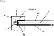
Fig. 3 ] is a schematic representation of a third example of sealing arrangement of the electrochromic cell in a device of the invention in cross section according to a plane perpendicular to the axis of the groove of the frame of the device wherein the groove differs from the groove according to the first example illustrated byfigure 1 . - The present invention concerns an optical electrochromic device comprising :
- an
electrochromic cell 1, - a
frame 2 with agroove 21, - said device being characterized in that it further comprises:
- at least one
elastic sealing part 3 arranged in saidgroove 21, and
- at least one
- said
electrochromic cell 1 is arranged in saidframe 2 and is compressed by said at least oneelastic sealing part 3. - According to the present construction, the
frame 2 is arranged according to a shape similar to the shape of theperipherical edge 11 of theelectrochromic cell 1 so that theframe 2 is positioned against theelectrochromic cell 1 and around theperipherical edge 11 of theelectrochromic cell 1. Theframe 2 comprises agroove 21 along at least a portion of its interior side, thisgroove 21 having dimensions in width similar to the thickness of theelectrochromic cell 1 so that theelectrochromic cell 1 be kept in position inside itscorresponding frame 2 without accidental removal. The presence of anelastic sealing 3 in the depth of thegroove 21 and having a width equal or thinner than the width of thegroove 21 realizes a peripheral surface along thegroove 21 to be in contact with at least a portion of theperipheral edge 11 of theelectrochromic cell 1 and provide a peripheral pressure against theedge 11 of thecell 1. Preferably, in a cross section perpendicular to the axis of thegroove 21, theelastic sealing 3 is wide enough to be in contact with the width of theperipheral edge 11 of thecell 1, from one face of thecell 1 to the other one. Because of its elastic properties, theelastic sealing 3 is able to support, endure and withstand deformation and perfectly match the surface of theperipheral edge 11 of theelectrochromic cell 1. According to such arrangement, under the pressure provided against theedge 11 of thecell 1, theelastic sealing 3 is able to be partially deformed to fill the width of thegroove 21 and to be in contact against the complete width of theedge 11 of thecell 1. According to specific example, because of its deformation properties, theelastic sealing part 3 may be compressed and support a 10% to 20% compression ratio of its material. Thus, anelastic sealing part 3 with a thickness about 1 mm positioned in thegroove 21 of theframe 2 may be deformed by the pressure from theperipheral edge 11 of theelectrochromic cell 1 to reach a thickness about 0,9 mm or even 0,8 mm. Said sealingpart 3 being lodged in thegroove 21 of theframe 2, theelastic sealing part 3 pressed by theperipheral edge 11 of thecell 1 against the depth of thegroove 21 may be deformed and enlarged according to a cross section perpendicular to the axis of thegroove 21 so that theelastic sealing part 3 is in contact with both internal sides of thegroove 21. - According to an example relative to a variant of the electrochromic device of the invention shown on
figure 3 , in cross section according to a plane perpendicular to the axis of the groove, thegroove 21 of theframe 2 is formed by two portions : - a first thinner and deeper portion arranged to receive the
elastic sealing part 3, and - a second wider and more superficial portion arranged to receive the
edge 11 of thecell 1. - The first thinner portion is positioned in the depth of the second wider portion. The width of the second wider and more superficial portion of the groove is similar to the thickness of the
edge 11 of thecell 1 so that thecell 1 can be maintained by this second wider portion once inserted. The depth of the first thinner portion is lower than the thickness of theelastic sealing part 3 so that, once lodged in this first thinner and deeper portion of thegroove 21, a portion of theelastic sealing 3 is at the junction between the first portion and the second portion of thegroove 21 so that theelastic sealing 3 is pressed against theedge 11 of thecell 1 inserted in the second portion of thegroove 21. Under pressure, theelastic sealing 3 may be partially deformed to fill the width of the first portion of thegroove 21 and to be in contact against a portion of theedge 11 of thecell 1 inserted in the second portion of thegroove 21. - The continuous contact of the
elastic sealing 3 against theperipheral edge 11 of theelectrochromic cell 1 provides a sealing so that no electrochromic liquid is able to flow outside thecell 1. Further, there is no risk of an unwanted infiltration of the oxygen inside thecell 1 providing an alteration of the electrochromic liquid of thecell 1. - It must be noticed that although the electrochromic device of the invention comprises one single
elastic sealing part 3 arranged in thegroove 21 of theframe 2, the device might be realized with at least two or severalelastic sealing parts 3 juxtaposed along the groove of theframe 2. According to this second arrangement, theperipheral edge 11 of theelectrochromic cell 1 would be in contact with severalelastic sealing parts 3. - According to an example relative to a variant of the electrochromic device of the invention, said
elastic sealing part 3 comprises elastomer. For example, the elastomer used is made of silicone rubber or at least one components providing similar or identical properties. Preferably, the elasticity modulus of the elastomer is comprised between 0.1 MPa and 10 Mpa. However, some elastomer may be chosen with an higher elasticity modulus about 30 MPa or even 2000 MPa. - According to an example relative to another variant of the electrochromic device of the invention, said
elastic sealing part 3 is arranged along all of saidgroove 21. Such arrangement provides an electrochromic device wherein the insertion of theelectrochromic cell 1 in theframe 2 is operated with the insertion of the edge of theelectrochromic cell 1 into thegroove 21 of theframe 2 so that theelastic sealing part 3 becomes in contact with the edge of thecell 1 and is pressed against thisperipheral edge 11 of thecell 1. As thegroove 21 may be positioned along the complete interior side of the frame, the completeperipheral edge 11 of theelectrochromic cell 1 is in contact with theelastic sealing part 3 so that a pressure is provided by this sealingpart 3 around the completeelectrochromic cell 1. - According to an example relative to another variant of the electrochromic device of the invention, said
elastic sealing part 3 is circular with an internal edge having a length smaller than the perimeter length of said electrochromic cell by less than 10 mm, preferably about 5 mm to 6 mm. The length of the internal edge of theelastic sealing part 3 and the length of theperipheral edge 11 of theelectrochromic cell 1 are almost similar according to a almost circular arrangement so that the width or diameter length of the internal edge of theelastic sealing part 3 is smaller than the width or diameter length of theelectrochromic cell 1 by 10 µm to 250 µm, preferably by 50 µm to 200 µm. Such arrangement with a smaller element mounted around a larger one guarantees an effective contact and a pressure of theelastic sealing part 3 against theperipheral edge 11 of theelectrochromic cell 1. Further, such arrangement guarantees that theelastic sealing part 3 is mounted with tension on theperipheral edge 11 of theelectrochromic cell 1 so that it may not be accidentally withdrawn from thecell 1. - According to an example relative to another variant of the electrochromic device of the invention, the cross section of said
elastic sealing part 3 is a ring. This cross-sectional ring of theelastic sealing part 3 has a perimeter length similar or even identical to the width of thegroove 21 inside theframe 2. The cross-sectional shape of theelastic sealing part 3 may be similar to the cross-sectional shape of thegroove 21 of theframe 2 so that theelastic sealing part 3 fulfills perfectly thegroove 21 of theframe 2. Further, theelastic sealing part 3 may be circular or similar to the shape of theframe 2 and/or to the shape of theperipheral edge 11 of theelectrochromic cell 1 so that theelastic sealing part 3 be easily inserted into theframe 2 of the electrochromic device. - According to an example relative to another variant of the electrochromic device of the invention, said
electrochromic cell 1 comprises at least twoshells shells shells shells electrochromic cell 1. The adhesive 14 used for such sealing may be a sealing glue classically used with theelectrochromic cell 1 and device or even a reinforcement glue. For example, this glue may be UV reactive or thermal reactive or made from components having similar properties. - According to an example relative to another variant of the electrochromic device of the invention, said
elastic sealing part 3 is arranged so as to cover said adhesive 14 and so as to almost entirely cover a peripheral edge of said two of said at least twoshells electrochromic cell 1, saidelastic sealing part 3 is arranged to not cover the edge portion of the device wherein the flex is positioned so that theelastic sealing part 3 provides an aperture making the flex in connection with the electrochromic formulation fulfilling the cell. Such arrangement combines the sealing properties of the adhesive 14 with the sealing properties of theelastic sealing 3. Further, as theelastic sealing part 3 is pressed against the peripheral edge of theshells elastic sealing part 3 provides a protection of the adhesive 14 arranged between two of said at least twoshells - According to an example relative to another variant of the electrochromic device of the invention, the electrochromic device further comprises a
plug 15 arranged between two of said at least twoshells plug 15 is positioned on a portion of the edges of the at least twoshells plug 15 is positioned between the twoshells shells shells plug 15 is able to be sealed with theshells plug 15 is realized by non-conductive materials to provide for the necessary electrical isolation of theelectrochromic cell 1 with respect to the outside. - According to an example relative to another variant of the electrochromic device of the invention, said
elastic sealing part 3 is arranged so as to cover saidplug 15. The cover of theplug 15 provides an additional sealing structure to impede a leak of electrochromic liquid and/or an infiltration of oxygen in thecell 1. Because of its deformable structure, theelastic sealing part 3 is able to be easily adjusted to the relief made by the surface ofplug 15 at its connection point with respect to the surface of theperipheral edge 11 of thecell 1. - According to an example relative to another variant of the electrochromic device of the invention, the electrochromic device further comprises a flex arranged to be connected to the conducting electrodes of the
electrochromic cell 1. This flex is positioned on a portion of the edges of the at least twoshells shells shells shells shells elastic sealing part 3 of the electrochromic device is arranged so as to not cover said flex. Thus, theelastic sealing part 3 does not prevent a connection between the electrochromic formulation fulfilling the cell and an electrical supply through the flex. - According to an example relative to another variant of the electrochromic device of the invention, the electrochromic device is an eyewear.
- An additional aspect of the invention concerns a method for sealing an electrochromic device, said electrochromic device comprising:
- an
electrochromic cell 1; and - a
frame 2 with agroove 21, - arranging at least one
elastic sealing part 3 in saidgroove 21, - arranging said
electrochromic cell 1 in saidframe 2 and compressing said at least oneelastic sealing part 3 by saidelectrochromic cell 1. - The compressing step is operated so that the
elastic sealing part 3 is pressed against the depth of thegroove 21. Theelastic sealing part 3 is deformed to fulfill the space between the deepest side of thegroove 21 and theperipheral edge 11 of theelectrochromic cell 1. - According to an example relative to a variant of the method of the invention, the
electrochromic cell 1 comprises at least twoshells - arranging adhesive 14 between two of said at least two
shells - This arranging step is operated previously to the insertion of the
electrochromic cell 1 in thegroove 21 of theframe 2. According to a particular example of this variant, the deposit of the adhesive 14 is carried out so that a portion or an area along the edge of theshells - According to an example relative to another variant of the method of the invention, the
electrochromic cell 1 further comprises: - arranging said
elastic sealing part 3 so as to cover said adhesive 14 between said at least twoshells shells - The covering step of the peripheral edge of the
shells elastic sealing part 3 may be carried out along the complete peripheral edge or at least one single portion of the peripheral edge of theshells peripheral edge 11 of theelectrochromic cell 1 is inserted into thegroove 21 of theframe 2. Alternatively, this covering step is carried out by mounting saidelastic sealing part 3 onto or around theperipheral edge 11 of theelectrochromic cell 1 previously to its insertion into thegroove 21 of theframe 2. This covering step is preferably carried out so that theelastic sealing part 3 provides an aperture on a portion of the peripheral edge allowing the flex to be in connection with the electrochromic formulation in the cell. - According to an example relative to another variant of the method of the invention, the method further comprises:
- arranging a
plug 15 between two of said at least twoshells - This arranging step of the
plug 15 is operated next to a deposit step of the adhesive 14 between the at least twoshells shells shells plug 15 is operated next to the filling of the cell with the electrochromic formulation through this aperture. The arranging step of theplug 15 provides the sealing or the clogging of the electrochromic cell so that theplug 15 is inserted between the twoshells plug 15 is operated previously to the covering step of theperipheral edge 11 of theelectrochromic cell 1 with at least a portion of theelastic sealing part 3. - According to an example relative to another variant of the method of the invention, the
electrochromic cell 1 further comprises: - arranging said
elastic sealing part 3 so as to cover saidplug 15. - This arranging step is operated jointly or simultaneously to the covering step of the
peripheral edge 11 of theelectrochromic cell 1 with at least a portion of theelastic sealing part 3. - The present invention is not limited to the embodiment described and shown in the attached drawings. Modifications remain possible, in particular from the point of view of the constitution of the various elements or by substitution of technical equivalents, without however leaving the field of protection of the invention.
Claims (15)
- An optical electrochromic device comprising:- an electrochromic cell (1),- a frame (2) with a groove (21),said device being characterized in that it further comprises:- at least one elastic sealing part (3) arranged in said groove (21), andsaid electrochromic cell (1) is arranged in said frame (2) and is compressed by said at least one elastic sealing part (3).
- An electrochromic device according to claim 1, characterized in that said electrochromic cell (1) comprises at least two shells (12, 13) and said electrochromic device further comprises adhesive (14) arranged between two of said at least two shells (12, 13).
- An electrochromic device according to claim 2, characterized in that said elastic sealing part (3) is arranged so as to cover said adhesive (14) and so as to almost entirely cover a peripheral edge of said two of said at least two shells (12, 13).
- An electrochromic device according to claim 2 or 3, characterized in that the electrochromic device further comprises a plug (15) arranged between two of said at least two shells (12, 13).
- An electrochromic device according to claim 4, characterized in that said elastic sealing part (3) is arranged so as to cover said plug (15).
- An electrochromic device according to any of the preceding claims, characterized in that said elastic sealing part (3) comprises elastomer.
- An electrochromic device according to any of the preceding claims, characterized in that said elastic sealing part (3) is arranged along all of said groove (21).
- An electrochromic device according to any of the preceding claims, characterized in that said elastic sealing part (3) is circular with an internal edge having a length smaller than the perimeter length of said electrochromic cell by less than 10 mm.
- An electrochromic device according to any of the preceding claims, characterized in that said elastic sealing part (3) is a ring.
- An electrochromic device according to any of the preceding claims, characterized in that the electrochromic device is an eyewear.
- A method for sealing an electrochromic device, said electrochromic device comprising:- an electrochromic cell (1); and- a frame (2) with a groove (21),said method being characterized in that it comprises:- arranging at least one elastic sealing part (3) in said groove (21),- arranging said electrochromic cell (1) in said frame (2) and compressing said at least one elastic sealing part (3) by said electrochromic cell (1).
- A method according to claim 11, characterized in that said electrochromic cell (1) comprises at least two shells (12, 13) and in that said method further comprises:- arranging adhesive (14) between two of said at least two shells (12, 13).
- A method according to claim 12, characterized in that said method further comprises:- arranging said elastic sealing (3) part so as to cover said adhesive (14) between said at least two shells (12, 13) and so as to almost entirely cover a peripheral edge (11) of said two of said at least two shells (12, 13).
- A method according to claim 12 or 13, characterized in that said method further comprises:- arranging a plug (15) between two of said at least two shells (12, 13).
- A method according to claim 14, characterized in that it further comprises:- arranging said elastic sealing part (3) so as to cover said plug (15).
Priority Applications (4)
| Application Number | Priority Date | Filing Date | Title |
|---|---|---|---|
| EP23307202.4A EP4571411A1 (en) | 2023-12-13 | 2023-12-13 | A framed electrochromic device |
| CN202480077845.2A CN122422812A (en) | 2023-12-13 | 2024-12-02 | Electrochromic device with frame |
| PCT/EP2024/084233 WO2025124950A1 (en) | 2023-12-13 | 2024-12-02 | A framed electrochromic device |
| KR1020267016794A KR20260115615A (en) | 2023-12-13 | 2024-12-02 | Electrochromic device with a frame |
Applications Claiming Priority (1)
| Application Number | Priority Date | Filing Date | Title |
|---|---|---|---|
| EP23307202.4A EP4571411A1 (en) | 2023-12-13 | 2023-12-13 | A framed electrochromic device |
Publications (1)
| Publication Number | Publication Date |
|---|---|
| EP4571411A1 true EP4571411A1 (en) | 2025-06-18 |
Family
ID=89385934
Family Applications (1)
| Application Number | Title | Priority Date | Filing Date |
|---|---|---|---|
| EP23307202.4A Pending EP4571411A1 (en) | 2023-12-13 | 2023-12-13 | A framed electrochromic device |
Country Status (4)
| Country | Link |
|---|---|
| EP (1) | EP4571411A1 (en) |
| KR (1) | KR20260115615A (en) |
| CN (1) | CN122422812A (en) |
| WO (1) | WO2025124950A1 (en) |
Citations (4)
| Publication number | Priority date | Publication date | Assignee | Title |
|---|---|---|---|---|
| US5455638A (en) * | 1993-09-10 | 1995-10-03 | Comdisco, Inc. | Electrochromic eyewear |
| EP2322984A1 (en) * | 2003-05-06 | 2011-05-18 | Gentex Corporation | Vehicular rearview mirror elements comprising a peripheral light blocking strip |
| US20180147993A1 (en) * | 2002-09-20 | 2018-05-31 | Donnelly Corporation | Method of manufacturing variable reflectance mirror reflective element for exterior mirror assembly |
| US20180196283A1 (en) * | 2015-07-10 | 2018-07-12 | Essilor International | Ophthalmic device comprising an electrochromic cell |
-
2023
- 2023-12-13 EP EP23307202.4A patent/EP4571411A1/en active Pending
-
2024
- 2024-12-02 KR KR1020267016794A patent/KR20260115615A/en active Pending
- 2024-12-02 WO PCT/EP2024/084233 patent/WO2025124950A1/en active Pending
- 2024-12-02 CN CN202480077845.2A patent/CN122422812A/en active Pending
Patent Citations (4)
| Publication number | Priority date | Publication date | Assignee | Title |
|---|---|---|---|---|
| US5455638A (en) * | 1993-09-10 | 1995-10-03 | Comdisco, Inc. | Electrochromic eyewear |
| US20180147993A1 (en) * | 2002-09-20 | 2018-05-31 | Donnelly Corporation | Method of manufacturing variable reflectance mirror reflective element for exterior mirror assembly |
| EP2322984A1 (en) * | 2003-05-06 | 2011-05-18 | Gentex Corporation | Vehicular rearview mirror elements comprising a peripheral light blocking strip |
| US20180196283A1 (en) * | 2015-07-10 | 2018-07-12 | Essilor International | Ophthalmic device comprising an electrochromic cell |
Also Published As
| Publication number | Publication date |
|---|---|
| KR20260115615A (en) | 2026-07-24 |
| CN122422812A (en) | 2026-07-17 |
| WO2025124950A1 (en) | 2025-06-19 |
Similar Documents
| Publication | Publication Date | Title |
|---|---|---|
| KR100653904B1 (en) | Touch panel device | |
| US5742006A (en) | Electric cell of the type comprising two parallel plates or substrates in particular made of plastic material separated from each other by a sealing frame | |
| TWI626364B (en) | Insulating glass unit and connecting key for engaging one of the opposite ends of the hollow metal insulating glass unit spacer | |
| CN101297233B (en) | Liquid crystal display device having a plurality of pixel electrodes | |
| US8363329B2 (en) | Liquid lens apparatus and manufacturing method of the same | |
| US20070252922A1 (en) | Liquid crystal display device | |
| US20110077063A1 (en) | Mobile terminal device and waterproof case structure | |
| US8238033B2 (en) | Liquid lens device and manufacturing method therefor | |
| CN107850817B (en) | Ophthalmic device including electrochromic unit | |
| TWI670849B (en) | Flexible display module and flexible display module preparation method | |
| US20190335029A1 (en) | Housing Assembly, Mobile Terminal, and Method for Assembling Housing Assembly | |
| CN110807989B (en) | display device | |
| US11106241B2 (en) | Display device | |
| CN219435196U (en) | Electrochromic device and rearview mirror | |
| JPH11126033A (en) | Electro-optical device and projection display device having the same | |
| CN113219713A (en) | Display panel and display device | |
| US20120223908A1 (en) | Display device | |
| WO2025124950A1 (en) | A framed electrochromic device | |
| US20060254107A1 (en) | Display device | |
| EP1521108A1 (en) | Optical modules employing glass-sealed fiber feedthru with c-seal | |
| AU3272300A (en) | Electrochromic element | |
| KR102292809B1 (en) | Display panel and manufacturing method thereof, display device, and terminal | |
| CN116339032B (en) | Electrochromic device, rearview mirror and preparation method of electrochromic device | |
| US20230367086A1 (en) | Optical module | |
| CN112946942A (en) | Display device and method for attaching liquid crystal panel and cover plate |
Legal Events
| Date | Code | Title | Description |
|---|---|---|---|
| PUAI | Public reference made under article 153(3) epc to a published international application that has entered the european phase |
Free format text: ORIGINAL CODE: 0009012 |
|
| STAA | Information on the status of an ep patent application or granted ep patent |
Free format text: STATUS: THE APPLICATION HAS BEEN PUBLISHED |
|
| AK | Designated contracting states |
Kind code of ref document: A1 Designated state(s): AL AT BE BG CH CY CZ DE DK EE ES FI FR GB GR HR HU IE IS IT LI LT LU LV MC ME MK MT NL NO PL PT RO RS SE SI SK SM TR |
|
| STAA | Information on the status of an ep patent application or granted ep patent |
Free format text: STATUS: REQUEST FOR EXAMINATION WAS MADE |
|
| 17P | Request for examination filed |
Effective date: 20251128 |