EP4571348A1 - Method for operating a radar device and radar device - Google Patents
Method for operating a radar device and radar device Download PDFInfo
- Publication number
- EP4571348A1 EP4571348A1 EP23217276.7A EP23217276A EP4571348A1 EP 4571348 A1 EP4571348 A1 EP 4571348A1 EP 23217276 A EP23217276 A EP 23217276A EP 4571348 A1 EP4571348 A1 EP 4571348A1
- Authority
- EP
- European Patent Office
- Prior art keywords
- cir
- tap
- taps
- target
- specified
- Prior art date
- Legal status (The legal status is an assumption and is not a legal conclusion. Google has not performed a legal analysis and makes no representation as to the accuracy of the status listed.)
- Pending
Links
Images




Classifications
-
- G—PHYSICS
- G01—MEASURING; TESTING
- G01S—RADIO DIRECTION-FINDING; RADIO NAVIGATION; DETERMINING DISTANCE OR VELOCITY BY USE OF RADIO WAVES; LOCATING OR PRESENCE-DETECTING BY USE OF THE REFLECTION OR RERADIATION OF RADIO WAVES; ANALOGOUS ARRANGEMENTS USING OTHER WAVES
- G01S7/00—Details of systems according to groups G01S13/00, G01S15/00, G01S17/00
- G01S7/02—Details of systems according to groups G01S13/00, G01S15/00, G01S17/00 of systems according to group G01S13/00
- G01S7/28—Details of pulse systems
- G01S7/285—Receivers
- G01S7/292—Extracting wanted echo-signals
- G01S7/2923—Extracting wanted echo-signals based on data belonging to a number of consecutive radar periods
-
- G—PHYSICS
- G01—MEASURING; TESTING
- G01S—RADIO DIRECTION-FINDING; RADIO NAVIGATION; DETERMINING DISTANCE OR VELOCITY BY USE OF RADIO WAVES; LOCATING OR PRESENCE-DETECTING BY USE OF THE REFLECTION OR RERADIATION OF RADIO WAVES; ANALOGOUS ARRANGEMENTS USING OTHER WAVES
- G01S7/00—Details of systems according to groups G01S13/00, G01S15/00, G01S17/00
- G01S7/02—Details of systems according to groups G01S13/00, G01S15/00, G01S17/00 of systems according to group G01S13/00
- G01S7/40—Means for monitoring or calibrating
-
- G—PHYSICS
- G01—MEASURING; TESTING
- G01S—RADIO DIRECTION-FINDING; RADIO NAVIGATION; DETERMINING DISTANCE OR VELOCITY BY USE OF RADIO WAVES; LOCATING OR PRESENCE-DETECTING BY USE OF THE REFLECTION OR RERADIATION OF RADIO WAVES; ANALOGOUS ARRANGEMENTS USING OTHER WAVES
- G01S13/00—Systems using the reflection or reradiation of radio waves, e.g. radar systems; Analogous systems using reflection or reradiation of waves whose nature or wavelength is irrelevant or unspecified
- G01S13/02—Systems using reflection of radio waves, e.g. primary radar systems; Analogous systems
- G01S13/0209—Systems with very large relative bandwidth, i.e. larger than 10 %, e.g. baseband, pulse, carrier-free, ultrawideband
-
- G—PHYSICS
- G01—MEASURING; TESTING
- G01S—RADIO DIRECTION-FINDING; RADIO NAVIGATION; DETERMINING DISTANCE OR VELOCITY BY USE OF RADIO WAVES; LOCATING OR PRESENCE-DETECTING BY USE OF THE REFLECTION OR RERADIATION OF RADIO WAVES; ANALOGOUS ARRANGEMENTS USING OTHER WAVES
- G01S7/00—Details of systems according to groups G01S13/00, G01S15/00, G01S17/00
- G01S7/02—Details of systems according to groups G01S13/00, G01S15/00, G01S17/00 of systems according to group G01S13/00
- G01S7/023—Interference mitigation, e.g. reducing or avoiding non-intentional interference with other HF-transmitters, base station transmitters for mobile communication or other radar systems, e.g. using electro-magnetic interference [EMI] reduction techniques
-
- G—PHYSICS
- G01—MEASURING; TESTING
- G01S—RADIO DIRECTION-FINDING; RADIO NAVIGATION; DETERMINING DISTANCE OR VELOCITY BY USE OF RADIO WAVES; LOCATING OR PRESENCE-DETECTING BY USE OF THE REFLECTION OR RERADIATION OF RADIO WAVES; ANALOGOUS ARRANGEMENTS USING OTHER WAVES
- G01S7/00—Details of systems according to groups G01S13/00, G01S15/00, G01S17/00
- G01S7/02—Details of systems according to groups G01S13/00, G01S15/00, G01S17/00 of systems according to group G01S13/00
- G01S7/28—Details of pulse systems
- G01S7/285—Receivers
- G01S7/292—Extracting wanted echo-signals
-
- G—PHYSICS
- G01—MEASURING; TESTING
- G01S—RADIO DIRECTION-FINDING; RADIO NAVIGATION; DETERMINING DISTANCE OR VELOCITY BY USE OF RADIO WAVES; LOCATING OR PRESENCE-DETECTING BY USE OF THE REFLECTION OR RERADIATION OF RADIO WAVES; ANALOGOUS ARRANGEMENTS USING OTHER WAVES
- G01S7/00—Details of systems according to groups G01S13/00, G01S15/00, G01S17/00
- G01S7/02—Details of systems according to groups G01S13/00, G01S15/00, G01S17/00 of systems according to group G01S13/00
- G01S7/41—Details of systems according to groups G01S13/00, G01S15/00, G01S17/00 of systems according to group G01S13/00 using analysis of echo signal for target characterisation; Target signature; Target cross-section
- G01S7/415—Identification of targets based on measurements of movement associated with the target
Definitions
- the present disclosure relates to a method for operating a radar device. Furthermore, the present disclosure relates to a radar device. Furthermore, the present disclosure relates to a computer implemented method for carrying out the proposed method.
- Target detection in ultra-wideband (UWB) radar systems may be sensitive towards variations in the channel response characterized by a second order statistics thereof.
- Unidentified noise sources may significantly tamper with these statistics, introducing variance changes in the received UWB signals. These changes are indistinguishable from statistical changes introduced by moving radar targets, making the latter hardly or no longer detectable.
- US 7,103,537 B2 discloses a system and a method for linear prediction.
- KR 10 1591163 B1 discloses UWB method and device for suppressing noise in UWB radar.
- a method for operating a radar device comprising the steps:
- the proposed method provides CIR 2 nd order statistics of impulse answers of radar measurements, wherein CIR taps with reduced variance are obtained, thus performing noise compensation and enabling an improved measurement of radar targets, in particular in a region of self-interference, i.e., the zero delay/range point.
- external effects may be suppressed, e.g. temperature-dependent effects, ageing effects, etc.
- the proposed method suggests to perform a simultaneous training and calculation procedure. As a result, advantageously, channel response measurements with minimal, consistent noise variance are obtained resembling that of general white measurement noise.
- a radar device configured to perform the proposed method.
- a computer implemented method comprising executable instructions which, when executed by a radar device cause said radar device to carry out the proposed method.
- a training setup is performed, wherein values of specified measured CIR-taps are stored in a signal vector, wherein for the training set zero-mean tap values are determined and stacked in a zero-mean signal vector and wherein for the target set one selected zero-mean signal vector is selected out of the signal vector.
- a predefined number of measurements is performed for each CIR-tap out of a number of specified CIR-taps, wherein corresponding tap indices contain a tap index of self-interference and specified tap indices with a lower tap index than self-interference. In this way, indices are taken, which most likely do not contain a radar target.
- the same predefined number of measurements is performed as for the training set. This supports a simplified calculation procedure.
- the auto-covariance matrix is individually determined for each CIR-tap of the target set.
- a CIR-target tap specific training set is used, wherein a selection of the CIR-taps of the training set is done in dependence of an expected radar target.
- This may be useful, if more distant radar targets are to be detected, in knowledge that near the CIR tap of self- interference there can be no radar target.
- the base set for each individual training step can be modified, which means that the base set can be individually selected for each CIR tap of the target set.
- UWB radar systems is sensitive towards variations in the channel response characterized by the second order statistics thereof. Unidentified noise sources may significantly tamper with these statistics, introducing variance changes in the UWB signals. These changes are indistinguishable from statistical changes introduced by moving radar targets, making the latter hard or not detectable.
- the algorithm described within the present disclosure operates onto UWB channel impulse responses (CIR) for radar channels.
- CIR channel impulse responses
- the proposed method applies a linear prediction procedure to estimate values of the target region CIR taps, where the CIR taps before the self-interference are weighted and added to predict any tap of the target region.
- a covariance matrix of all involved taps is estimated on the basis of a CIR data set. Multiple options are outlined how to choose the training set region.
- Monostatic UWB radar channel impulse response variance estimate is used to detect moving targets via threshold test.
- Non-stationary noise sources introduce higher variance in the self-interference region and hence destroy detectability
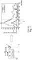
- FIG. 1 illustrates an underlying problem of the proposed method.
- a UWB radar system 100 with a transmitter TX and a receiver RX, together with a moving radar target T in a small distance d of appr. ⁇ 1 m.
- the amplitude diagram on the right hand side of FIG. 1 shows the tap index on its x-axis, which corresponds to a distance d between antenna and radar target T, wherein CIR-tap thirteen represents SI self-interference ("zero-point").
- CIR-tap thirteen represents SI self-interference ("zero-point").
- CIR taps with index twenty two and lower represent radar targets close to the device (distances d appr. ⁇ 1m).
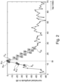
- FIG. 2 shows a first step of the proposed method of linear prediction with a training.
- CIR tap indices are selected to obtain training- and target sets, wherein no radar target T is detected in this case.
- FIG. 2 shows those taps X 9 ...X 13 of the training set as small circles before the tap of self-interference SI.
- the target set Y comprises CIR taps where a radar target T could be present, which can be the case for e.g. CIR taps Y 14 to Y 25 .
- the target set represent CIR-taps in a region of interest, where radar targets T are to be expected, e.g. after self-interference SI.
- Those targets are shown in FIG. 2 as small squares.
- Y 14 , 15 , ... , 22
- Exemplary measurements may contain 1.000 frame numbers, an exemplary size of Sx may be [N x M] and an exemplary size of the target vector s y may be [N x 1].
- a cross-covariance vector is estimated between taps of the training set and one specific target tap of interest (in particular, a target tap with an expected existence of radar targets T) via:
- C ⁇ Xy 1 / N ⁇ 1 S X T s y
- the algorithm output of equation (10) is then repeated for another target tap of the target set.
- the training and prediction procedure shown is carried out simultaneously, which helps to ensure that changing parameters (e.g. temperature, ageing effects, etc.) are taken into account by the proposed method.
- changing parameters e.g. temperature, ageing effects, etc.
- FIG. 4 shows an amplitude diagram with exemplary results according to the proposed method.
- a gain loss may be appr. > 20 dB, which may improve a detectability of weak radar targets T in said region R1.
- FIGs. 5 and 6 show alternatives of training sets depending on target taps of interest.
- the training set can be selected depending on a region of potential radar targets T.
- the above mentioned target taps are used to run the above illustrated process with training setup, training and prediction.
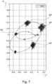
- FIGs. 7 to 9 are alternative diagrams showing benefits and advantages of the proposed method.
- FIG. 7 shows CIR-taps in a complex I/Q-diagram (quadrature components I, Q of the receiver) and shows that the proposed method reduces noise power NP is advantageously "condensed" to little areas with less noise power NP.
- a noise power NP has an amount as illustrated with cloud-like-formation diagrams in FIG 7 .
- FIG. 8 is a range Doppler plot over frequency f without noise compensation according to the proposed method.
- a moving radar target T at appr. frequency sixteen is almost covered due to noise at a distance between appr. eighteen and appr. twenty-one.
- the y-axis here describes the tap indices, which could be mapped to a distance "d", i.e. tap 13 corresponds to distance 0, this also applies to FIG. 9 .
- FIG. 9 shows a further range Doppler plot over frequency f with performed noise compensation according to the proposed method.
- One recognizes much more reduced noise power compared to FIG. 8 .
- a radar target T at a distance between appr. eighteen and appr. twenty-one and a frequency of appr. sixteen is much better detectable than in the scenario of FIG. 8 .
- FIG. 10 shows a block diagram of a UWB radar system 100 with a radar device 10 being configured to perform the proposed method.
- FIG. 11 shows a flow of the proposed method.
- pulse radar measurements are performed with a determination of measured CIR-taps.
- a specified training set of measured CIR-taps is determined.
- a specified target set of measured CIR-taps is determined in a region of interest with expected radar targets T.
- a step 230 an auto-covariance matrix of CIR-taps of the specified training set is determined.
- a cross-covariance vector is determined between CIR-taps of the specified training set and a specified target CIR tap of the specified target set.
- a value for the specified target CIR-tap is determined, wherein the predicted value is subtracted from the corresponding value of the specified target CIR tap.
- UWB radar systems e.g. in UWB radar systems.
- An exemplary application of said UWB radar systems could be a detection of a breathing person inside a vehicle (child presence detection).
- the proposed method can be implemented at least partially as a software which can be stored in a computer readable memory or at least partially as a firmware or at least partially as a hardware (e.g. an UWB radar IC).
- a software which can be stored in a computer readable memory or at least partially as a firmware or at least partially as a hardware (e.g. an UWB radar IC).
- the systems and methods described herein may at least partially be embodied by a computer program or a plurality of computer programs, which may exist in a variety of forms both active and inactive in a single computer system or across multiple computer systems.
- they may exist as software program(s) comprised of program instructions in source code, object code, executable code or other formats for performing some of the steps.
- Any of the above may be embodied on a computer readable medium, which may include storage devices and signals, in compressed or uncompressed form.
- processor or “processing unit” refers to a data processing circuit that may be a microprocessor, a co-processor, a microcontroller, a microcomputer, a central processing unit, a field programmable gate array (FPGA), a programmable logic circuit, or any circuit that manipulates signals (analog or digital) based on operational instructions that are stored in a memory.
- memory refers to a storage circuit or multiple storage circuits such as read-only memory, random access memory, volatile memory, non-volatile memory, static memory, dynamic memory, flash memory, cache memory, or any circuit that stores digital information.
- a "computer-readable medium” or “storage medium” may be any means that can contain, store, communicate, propagate, or transport a computer program for use by or in connection with the instruction execution system, apparatus, or device.
- the computer-readable medium may be, for example but not limited to, an electronic, magnetic, optical, electromagnetic, infrared, or semiconductor system, apparatus, device, or propagation medium.
- the computer-readable medium may include the following: an electrical connection having one or more wires, a portable computer diskette, a random-access memory (RAM), a read-only memory (ROM), an erasable programmable read-only memory (EPROM or Flash memory), an optical fiber, a portable compact disc read-only memory (CDROM), a digital versatile disc (DVD), a Blu-ray disc (BD), and a memory card.
- RAM random-access memory
- ROM read-only memory
- EPROM or Flash memory erasable programmable read-only memory
- CDROM compact disc read-only memory
- DVD digital versatile disc
- BD Blu-ray disc
Landscapes
- Engineering & Computer Science (AREA)
- Radar, Positioning & Navigation (AREA)
- Remote Sensing (AREA)
- Computer Networks & Wireless Communication (AREA)
- Physics & Mathematics (AREA)
- General Physics & Mathematics (AREA)
- Radar Systems Or Details Thereof (AREA)
Abstract
Method for operating a radar device (10), comprising the steps:- performing pulse radar measurements with a determination of measured CIR-taps;- determining a specified training set of measured CIR-taps;- determining a specified target set of measured CIR-taps in a region of interest with expected radar targets (T);- determining an auto-covariance matrix of CIR-taps of the specified training set;- determining a cross-covariance vector between CIR-taps of the specified training set and a specified target CIR tap of the specified target set; and- predicting a value for the specified target CIR-tap, wherein the predicted value is subtracted from the corresponding value of the specified target CIR tap.
Description
- The present disclosure relates to a method for operating a radar device. Furthermore, the present disclosure relates to a radar device. Furthermore, the present disclosure relates to a computer implemented method for carrying out the proposed method.
- Target detection in ultra-wideband (UWB) radar systems may be sensitive towards variations in the channel response characterized by a second order statistics thereof. Unidentified noise sources may significantly tamper with these statistics, introducing variance changes in the received UWB signals. These changes are indistinguishable from statistical changes introduced by moving radar targets, making the latter hardly or no longer detectable.
-
US 7,103,537 B2 discloses a system and a method for linear prediction. -
US 7,065,486 B1 discloses linear prediction based noise suppression. -
KR 10 1591163 B1 - It is an object to provide an improved method for operating a radar device.
- According to a first aspect of the present disclosure there is provided a method for operating a radar device, comprising the steps:
- performing pulse radar measurements with a determination of measured CIR-taps;
- determining a specified training set of measured CIR-taps;
- determining a specified target set of measured CIR-taps in a region of interest with expected radar targets;
- determining an auto-covariance matrix of CIR-taps of the specified training set;
- determining a cross-covariance vector between CIR-taps of the specified training set and a specified target CIR tap of the specified target set, and
- predicting a value for the specified target CIR-tap, wherein the predicted value is subtracted from the corresponding value of the specified target CIR tap.
- The proposed method provides CIR 2nd order statistics of impulse answers of radar measurements, wherein CIR taps with reduced variance are obtained, thus performing noise compensation and enabling an improved measurement of radar targets, in particular in a region of self-interference, i.e., the zero delay/range point. In this way, external effects may be suppressed, e.g. temperature-dependent effects, ageing effects, etc. The proposed method suggests to perform a simultaneous training and calculation procedure. As a result, advantageously, channel response measurements with minimal, consistent noise variance are obtained resembling that of general white measurement noise.
- According to a further aspect there is provided a radar device configured to perform the proposed method.
- According to a further aspect there is provided a computer implemented method comprising executable instructions which, when executed by a radar device cause said radar device to carry out the proposed method.
- According to one or more embodiments, in order to provide the training set and the target set, a training setup is performed, wherein values of specified measured CIR-taps are stored in a signal vector, wherein for the training set zero-mean tap values are determined and stacked in a zero-mean signal vector and wherein for the target set one selected zero-mean signal vector is selected out of the signal vector.
- According to one or more embodiments, for the training set a predefined number of measurements is performed for each CIR-tap out of a number of specified CIR-taps, wherein corresponding tap indices contain a tap index of self-interference and specified tap indices with a lower tap index than self-interference. In this way, indices are taken, which most likely do not contain a radar target.
- According to one or more embodiments, for the target set the same predefined number of measurements is performed as for the training set. This supports a simplified calculation procedure.
- According to one or more embodiments, the auto-covariance matrix is individually determined for each CIR-tap of the target set.
- According to one or more embodiments, a CIR-target tap specific training set is used, wherein a selection of the CIR-taps of the training set is done in dependence of an expected radar target. This may be useful, if more distant radar targets are to be detected, in knowledge that near the CIR tap of self- interference there can be no radar target. Advantageously, the base set for each individual training step can be modified, which means that the base set can be individually selected for each CIR tap of the target set.
- The aspects defined above and also further aspects of the present disclosure are apparent from the examples of embodiment to be described hereinafter with reference to the appended drawings, which are explained with reference to examples of embodiment. However, the disclosure is not limited to the described examples of embodiment.
- All illustrations in the drawings are schematical. It is noted, that in different figures, similar or identical elements or features are provided with the same reference signs or with reference signs, which are different from the corresponding reference signs only within the first digit. In order to avoid unnecessary repetitions elements or features which have already been elucidated with respect to a previously described embodiment are not elucidated again at a later position of the description.
-
FIG. 1 shows a diagram with conventional scenario of an estimation of monostatic UWB radar channel impulse responses; -
FIG. 2 shows a first step of the proposed method of linear prediction with a training procedure; -
FIG. 3 shows a CIR amplitude measurement set according to the proposed method; -
FIG. 4 shows the second order statistics of the measurements fromFIG. 3 ; -
FIG. 5 shows an alternative selection of a training set of CIR-taps; -
FIG. 6 shows a further alternative selection of a training set of CIR taps; -
FIG. 7 shows a complex I/Q-diagram according to the proposed method; -
FIG. 8 shows a conventional power spectral density diagram; -
FIG. 9 shows a power spectral density diagram according to the proposed method; -
FIG. 10 shows a block diagram of a proposed UWB radar system; and -
FIG. 11 shows in principle a flow diagram of the proposed method. - Radar target detection in ultra-wideband (UWB) radar systems is sensitive towards variations in the channel response characterized by the second order statistics thereof. Unidentified noise sources may significantly tamper with these statistics, introducing variance changes in the UWB signals. These changes are indistinguishable from statistical changes introduced by moving radar targets, making the latter hard or not detectable.
- The present disclosure tackles this issue via an application of a linear prediction procedure operating on UWB channel impulse responses (CIRs), using a 2nd order statistics of CIR taps before the self-interference to predict taps that represent range regions of interest. The predicted signal is subtracted from the original signal, resulting in a significantly reduced noise variance.
- The algorithm described within the present disclosure operates onto UWB channel impulse responses (CIR) for radar channels. The CIRs are separated into two parts:
- (i) a training region ("training set"), e.g., CIR taps before the self-interference (i.e., the zero delay/range point), and
- (ii) a target region ("target set") representing a region of interest of potential radar targets, e.g., CIR taps slightly after the region of self-interference to detect close radar targets T.
- The proposed method applies a linear prediction procedure to estimate values of the target region CIR taps, where the CIR taps before the self-interference are weighted and added to predict any tap of the target region. To this end, a covariance matrix of all involved taps is estimated on the basis of a CIR data set. Multiple options are outlined how to choose the training set region.
- Monostatic UWB radar channel impulse response variance estimate is used to detect moving targets via threshold test. Non-stationary noise sources introduce higher variance in the self-interference region and hence destroy detectability
-
FIG. 1 illustrates an underlying problem of the proposed method. On the left hand side there is shown aUWB radar system 100 with a transmitter TX and a receiver RX, together with a moving radar target T in a small distance d of appr. < 1 m. Self-interference SI takes place at a distance d = 0, i.e. at the position of the receiver RX, because the receiver RX also detects outgoing signals of the transmitter TX. - The amplitude diagram on the right hand side of
FIG. 1 shows the tap index on its x-axis, which corresponds to a distance d between antenna and radar target T, wherein CIR-tap thirteen represents SI self-interference ("zero-point"). For the right hand side amplitude diagram ofFIG. 1 there is performed a specific number of CIR measurements (e.g. appr. 1.000) with performed first and second order statistics in order to obtain a mean-curve and a variance-curve of measurement data. If the variance surpasses a specific threshold thr, a radar target T is detected. A sharp rise of the variance curve is indicated in a region R. In case, that there is a moving radar target T in the region R, said radar target T could hardly be detected due to noise, which is higher than a threshold level thr, which is exemplary appr. -80dB. For weak radar targets T (e.g. a breathing person within a vehicle) this could be problematic to be detected. - One recognizes a CIR tap with index thirteen, which corresponds to self-interference SI, i.e., distance d = 0. Furthermore, CIR taps with index twenty two and lower represent radar targets close to the device (distances d appr. < 1m).
-
FIG. 2 shows a first step of the proposed method of linear prediction with a training. CIR tap indices are selected to obtain training- and target sets, wherein no radar target T is detected in this case. The training set contains a specific number M of CIR taps, that are not affected by the propagation channel, i.e. at a tap index of self-interference SI or before
- X ...
- training set (certain CIR tap indices)
- M ...
- size of training set (i.e. number of CIR taps)
- With respect to
FIG. 2 , e.g. five CIR taps (M = 5) taps X9...X13 are selected including the CIR-tap X13 of self-interference SI.FIG. 2 shows those taps X9...X13 of the training set as small circles before the tap of self-interference SI. The target set Y comprises CIR taps where a radar target T could be present, which can be the case for e.g. CIR taps Y14 to Y25. In other words, the target set represent CIR-taps in a region of interest, where radar targets T are to be expected, e.g. after self-interference SI. Those targets are shown inFIG. 2 as small squares.
- Y ...
- target set (certain CIR tap indices)
- It is proposed to perform a prediction for each CIR tap individually, e.g. y = 15 for
tap 15. - y ...
- single index from target set Y (corresponds to selected radar target)
-
FIG. 3 shows in principle a training setup for each CIR tap, wherein measured values are stored in a signal vector as follows:
- i ...
- index of CIR-tap
- N ...
- number of measurements (frames)
- T...
- transpose operator
- Afterwards, zero-mean tap values are calculated via the following equation (4):

- Afterwards, zero-mean signal vectors are stacked into a matrix as follows:

- Sx ... training set matrix (rows correspond to CIR values from the selected index set (length M), columns correspond to realizations of one CIR tap (length N)) Afterwards, one zero-mean signal vector is selected from the target set:

- sy ...
- target vector (realizations of one CIR tap which is to be predicted (length N))
- This means, that any zero-mean signal vector is taken from the target set Y = [14, 15, ..., 22].
- Exemplary measurements may contain 1.000 frame numbers, an exemplary size of Sx may be [N x M] and an exemplary size of the target vector sy may be [N x 1].
- A next step of the proposed linear prediction process may contain a training process, wherein an auto-covariance matrix of taps of the training set is estimated via:

- Next, a cross-covariance vector is estimated between taps of the training set and one specific target tap of interest (in particular, a target tap with an expected existence of radar targets T) via:

- Cxy ...
- cross-covariance vector between training set CIR taps and one target CIR tap,
- In a next step, a prediction is done, wherein an estimated matrix/vector is used to get a weight vector as follows:

- Finally, a predicted CIR tap value is subtracted to get an estimated CIR tap value with reduced variance:

- The training and prediction procedure shown is carried out simultaneously, which helps to ensure that changing parameters (e.g. temperature, ageing effects, etc.) are taken into account by the proposed method.
-
FIG. 4 shows an amplitude diagram with exemplary results according to the proposed method. One recognizes mean-, variance- and variance-after-compensation curves. In a critical region R1, i.e. around CIR tap index thirteen a gain loss may be appr. > 20 dB, which may improve a detectability of weak radar targets T in said region R1. - Furthermore, also in a region R2 a reconstructed target CIR tap according to the proposed method may have reduced variance:

- ŝy ...
- reconstructed CIR-tap
- Furthermore, in a region R3 an equal variance if unknown noise has negligible impact to the target tap.
-
FIGs. 5 and6 show alternatives of training sets depending on target taps of interest. In other words, the training set can be selected depending on a region of potential radar targets T.FIG. 5 shows that for a target tap Y14 (regarding a target near self-interference) the following training set is used:
-
FIG. 6 shows that a higher distance target tap Y21 (more distant radar target T) the following training set is used:
- The above mentioned target taps are used to run the above illustrated process with training setup, training and prediction.
- The
FIGs. 7 to 9 are alternative diagrams showing benefits and advantages of the proposed method.FIG. 7 shows CIR-taps in a complex I/Q-diagram (quadrature components I, Q of the receiver) and shows that the proposed method reduces noise power NP is advantageously "condensed" to little areas with less noise power NP. In contrast, without performing the proposed method, a noise power NP has an amount as illustrated with cloud-like-formation diagrams inFIG 7 . -
FIG. 8 is a range Doppler plot over frequency f without noise compensation according to the proposed method. One recognizes, that a moving radar target T at appr. frequency sixteen is almost covered due to noise at a distance between appr. eighteen and appr. twenty-one. The y-axis here describes the tap indices, which could be mapped to a distance "d", i.e. tap 13 corresponds to distance 0, this also applies toFIG. 9 . -
FIG. 9 shows a further range Doppler plot over frequency f with performed noise compensation according to the proposed method. One recognizes much more reduced noise power compared toFIG. 8 . As a result, a radar target T at a distance between appr. eighteen and appr. twenty-one and a frequency of appr. sixteen is much better detectable than in the scenario ofFIG. 8 . - Summarizing, a linear prediction in the context of UWB radar on the one hand, and for noise suppression of radio channel impulse responses on the other hand is proposed.
-
FIG. 10 shows a block diagram of aUWB radar system 100 with aradar device 10 being configured to perform the proposed method. -
FIG. 11 shows a flow of the proposed method. - In a
step 200 pulse radar measurements are performed with a determination of measured CIR-taps. - In a step 210 a specified training set of measured CIR-taps is determined.
- In a step 220 a specified target set of measured CIR-taps is determined in a region of interest with expected radar targets T.
- In a
step 230 an auto-covariance matrix of CIR-taps of the specified training set is determined. - In a step 240 a cross-covariance vector is determined between CIR-taps of the specified training set and a specified target CIR tap of the specified target set.
- Finally, in a
step 250, a value for the specified target CIR-tap is determined, wherein the predicted value is subtracted from the corresponding value of the specified target CIR tap. - The present disclosure is applicable in radar areas, e.g. in UWB radar systems. An exemplary application of said UWB radar systems could be a detection of a breathing person inside a vehicle (child presence detection).
- The proposed method can be implemented at least partially as a software which can be stored in a computer readable memory or at least partially as a firmware or at least partially as a hardware (e.g. an UWB radar IC).
- It should be noted that the term "comprising" does not exclude other elements or steps and "a" or "an" does not exclude a plurality. Also elements described in association with different embodiments may be combined. It should also be noted that reference signs in the claims should not be construed as limiting the scope of the claims.
- The systems and methods described herein may at least partially be embodied by a computer program or a plurality of computer programs, which may exist in a variety of forms both active and inactive in a single computer system or across multiple computer systems. For example, they may exist as software program(s) comprised of program instructions in source code, object code, executable code or other formats for performing some of the steps. Any of the above may be embodied on a computer readable medium, which may include storage devices and signals, in compressed or uncompressed form.
- The term "processor" or "processing unit" refers to a data processing circuit that may be a microprocessor, a co-processor, a microcontroller, a microcomputer, a central processing unit, a field programmable gate array (FPGA), a programmable logic circuit, or any circuit that manipulates signals (analog or digital) based on operational instructions that are stored in a memory. The term "memory" refers to a storage circuit or multiple storage circuits such as read-only memory, random access memory, volatile memory, non-volatile memory, static memory, dynamic memory, flash memory, cache memory, or any circuit that stores digital information.
- As used herein, a "computer-readable medium" or "storage medium" may be any means that can contain, store, communicate, propagate, or transport a computer program for use by or in connection with the instruction execution system, apparatus, or device. The computer-readable medium may be, for example but not limited to, an electronic, magnetic, optical, electromagnetic, infrared, or semiconductor system, apparatus, device, or propagation medium. More specific examples (non-exhaustive list) of the computer-readable medium may include the following: an electrical connection having one or more wires, a portable computer diskette, a random-access memory (RAM), a read-only memory (ROM), an erasable programmable read-only memory (EPROM or Flash memory), an optical fiber, a portable compact disc read-only memory (CDROM), a digital versatile disc (DVD), a Blu-ray disc (BD), and a memory card.
- It is noted that the embodiments above have been described with reference to different subject-matters. In particular, some embodiments may have been described with reference to method-type claims whereas other embodiments may have been described with reference to apparatus-type claims. However, a person skilled in the art will gather from the above that, unless otherwise indicated, in addition to any combination of features belonging to one type of subject-matter also any combination of features relating to different subject-matters, in particular a combination of features of the method-type claims and features of the apparatus-type claims, is considered to be disclosed with this document.
- Moreover, it is noted that in an effort to provide a concise description of the illustrative embodiments, implementation details which fall into the customary practice of the skilled person may not have been described. It should be appreciated that in the development of any such implementation, as in any engineering or design project, numerous implementation-specific decisions must be made in order to achieve the developers' specific goals, such as compliance with system-related and business-related constraints, which may vary from one implementation to another. Moreover, it should be appreciated that such a development effort might be complex and time consuming, but would nevertheless be a routine undertaking of design, fabrication, and manufacture for those of ordinary skill.
- It has to be noted that embodiments have been described with reference to different subject matters. In particular, some embodiments have been described with reference to method type claims whereas other embodiments have been described with reference to apparatus type claims. However, a person skilled in the art will gather from the above and the following description that, unless other notified, in addition to any combination of features belonging to one type of subject matter also any combination between features relating to different subject matters, in particular between features of the method type claims and features of the apparatus type claims is considered as to be disclosed with this application.
-
- 10
- radar device
- 100
- UWB radar system
- 200...250
- method steps
- R, R1-R3
- region
- SI
- self-interference
- thr
- threshold
- T
- radar target
Claims (9)
- Method for operating a radar device (10), comprising the steps:- performing pulse radar measurements with a determination of measured CIR-taps;- determining a specified training set of measured CIR-taps;- determining a specified target set of measured CIR-taps in a region of interest with expected radar targets (T);- determining an auto-covariance matrix of CIR-taps of the specified training set;- determining a cross-covariance vector between CIR-taps of the specified training set and a specified target CIR tap of the specified target set; and- predicting a value for the specified target CIR-tap, wherein the predicted value is subtracted from the corresponding value of the specified target CIR tap.
- Method according to claim 1, wherein in order to provide the training set and the target set, a training setup is performed, wherein values of specified measured CIR-taps are stored in a signal vector (si), wherein for the training set zero-mean tap values are determined and stacked in a zero-mean signal vector (Sx) and wherein for the target set one selected zero-mean signal vector is selected out of the signal vector (si).
- Method according to claim 1 or 2, wherein for the training set a predefined number (N) of measurements is performed for each CIR-tap out of a number of specified CIR-taps, wherein corresponding tap indices contain a tap index of self-interference and specified tap indices with a lower tap index than self-interference (SI).
- Method according to claim 2 or 3, wherein for the target set the same predefined number (N) of measurements is performed as for the training set.
- Method according to any of the preceding claims, wherein the auto-covariance matrix is individually determined for each CIR-tap of the target set.
- Method according to any of the preceding claims, wherein a CIR-target tap specific training set is used, wherein a selection of the CIR-taps of the training set is done in dependence of an expected radar target (T).
- Radar device (10) configured to perform the method of any of the preceding claims.
- Radar system (100) comprising a radar device (10) according to claim 7.
- Computer implemented method comprising executable instructions storable on computer-readable storage medium which, when executed by a device (10) cause said device (10) to carry out the method of any of claims 1 to 6.
Priority Applications (3)
| Application Number | Priority Date | Filing Date | Title |
|---|---|---|---|
| EP23217276.7A EP4571348A1 (en) | 2023-12-15 | 2023-12-15 | Method for operating a radar device and radar device |
| CN202411645109.0A CN120161422A (en) | 2023-12-15 | 2024-11-18 | Method for operating a radar device and radar device |
| US18/976,979 US20250199115A1 (en) | 2023-12-15 | 2024-12-11 | Method for operating a radar device and radar device |
Applications Claiming Priority (1)
| Application Number | Priority Date | Filing Date | Title |
|---|---|---|---|
| EP23217276.7A EP4571348A1 (en) | 2023-12-15 | 2023-12-15 | Method for operating a radar device and radar device |
Publications (1)
| Publication Number | Publication Date |
|---|---|
| EP4571348A1 true EP4571348A1 (en) | 2025-06-18 |
Family
ID=89223611
Family Applications (1)
| Application Number | Title | Priority Date | Filing Date |
|---|---|---|---|
| EP23217276.7A Pending EP4571348A1 (en) | 2023-12-15 | 2023-12-15 | Method for operating a radar device and radar device |
Country Status (3)
| Country | Link |
|---|---|
| US (1) | US20250199115A1 (en) |
| EP (1) | EP4571348A1 (en) |
| CN (1) | CN120161422A (en) |
Citations (4)
| Publication number | Priority date | Publication date | Assignee | Title |
|---|---|---|---|---|
| US7065486B1 (en) | 2002-04-11 | 2006-06-20 | Mindspeed Technologies, Inc. | Linear prediction based noise suppression |
| US7103537B2 (en) | 2000-10-13 | 2006-09-05 | Science Applications International Corporation | System and method for linear prediction |
| KR101591163B1 (en) | 2014-03-21 | 2016-02-03 | 한양대학교 산학협력단 | Method and Device for Suppressing Noise in UWB Radar |
| EP3869223A1 (en) * | 2020-02-22 | 2021-08-25 | Origin Wireless, Inc. | System and method for wireless material sensing based on multipath channel information |
-
2023
- 2023-12-15 EP EP23217276.7A patent/EP4571348A1/en active Pending
-
2024
- 2024-11-18 CN CN202411645109.0A patent/CN120161422A/en active Pending
- 2024-12-11 US US18/976,979 patent/US20250199115A1/en active Pending
Patent Citations (4)
| Publication number | Priority date | Publication date | Assignee | Title |
|---|---|---|---|---|
| US7103537B2 (en) | 2000-10-13 | 2006-09-05 | Science Applications International Corporation | System and method for linear prediction |
| US7065486B1 (en) | 2002-04-11 | 2006-06-20 | Mindspeed Technologies, Inc. | Linear prediction based noise suppression |
| KR101591163B1 (en) | 2014-03-21 | 2016-02-03 | 한양대학교 산학협력단 | Method and Device for Suppressing Noise in UWB Radar |
| EP3869223A1 (en) * | 2020-02-22 | 2021-08-25 | Origin Wireless, Inc. | System and method for wireless material sensing based on multipath channel information |
Also Published As
| Publication number | Publication date |
|---|---|
| US20250199115A1 (en) | 2025-06-19 |
| CN120161422A (en) | 2025-06-17 |
Similar Documents
| Publication | Publication Date | Title |
|---|---|---|
| US8138963B1 (en) | Method for detecting targets using space-time adaptive processing and shared knowledge of the environment | |
| US6970605B1 (en) | Image processing apparatus, image processing method, noise-amount estimate apparatus, noise-amount estimate method, and storage medium | |
| KR100984150B1 (en) | Improving Target Detection Using Temporal and Spatial Integration | |
| US7286079B2 (en) | Method and apparatus for detecting slow-moving targets in high-resolution sea clutter | |
| US20060125682A1 (en) | System and method for reducing a radar interference signal | |
| KR20100121108A (en) | Radar signals clustering method using frequency modulation characteristics and combination characteristics of signals, and system for receiving and processing radar signals using the same | |
| US9465063B2 (en) | Method and system for the estimation and cancellation of multipath delay of electromagnetic signals, in particular SSR replies | |
| CN115128548B (en) | SAR radio frequency interference detection method | |
| US6772100B2 (en) | Multipath mitigation filter | |
| CN107076831A (en) | radar sensor | |
| Fuchs et al. | Multiantenna radar signal interference mitigation using complex-valued convolutional neural networks | |
| Ochoa et al. | Fast estimation of earthquake epicenter distance using a single seismological station with machine learning techniques | |
| CN120669233B (en) | Method, device, equipment and medium for generating underwater target detection results based on combined waveform | |
| EP4365629A1 (en) | A method for operating a uwb communication unit as a radar device | |
| US20250199115A1 (en) | Method for operating a radar device and radar device | |
| US20130257645A1 (en) | Target visibility enhancement system | |
| KR102391935B1 (en) | Apparatus and method for estimating angle of the low velocity target in the radar | |
| CN107315169B (en) | Clutter covariance matrix estimation method based on second-order statistic similarity | |
| EP2684073B1 (en) | Radio frequency digital receiver system and method | |
| Reimer et al. | Estimating self-clutter of the multiple-pulse technique | |
| KR101877216B1 (en) | Apparatus and method for compensating for phase error of target detecting device | |
| US10935648B2 (en) | Method of processing a signal formed of a sequence of pulses | |
| US20260079228A1 (en) | Target trajectory estimating device and target trajectory estimating method | |
| KR102756797B1 (en) | System and method for suppressing harmonics | |
| US20250377443A1 (en) | Adaptive Thresholding Technique for Single Scatterer Tests |
Legal Events
| Date | Code | Title | Description |
|---|---|---|---|
| PUAI | Public reference made under article 153(3) epc to a published international application that has entered the european phase |
Free format text: ORIGINAL CODE: 0009012 |
|
| STAA | Information on the status of an ep patent application or granted ep patent |
Free format text: STATUS: THE APPLICATION HAS BEEN PUBLISHED |
|
| AK | Designated contracting states |
Kind code of ref document: A1 Designated state(s): AL AT BE BG CH CY CZ DE DK EE ES FI FR GB GR HR HU IE IS IT LI LT LU LV MC ME MK MT NL NO PL PT RO RS SE SI SK SM TR |
|
| STAA | Information on the status of an ep patent application or granted ep patent |
Free format text: STATUS: REQUEST FOR EXAMINATION WAS MADE |
|
| 17P | Request for examination filed |
Effective date: 20251218 |