EP4571341A1 - Process of managing an electrochemical battery and system for managing an electrochemical battery - Google Patents
Process of managing an electrochemical battery and system for managing an electrochemical battery Download PDFInfo
- Publication number
- EP4571341A1 EP4571341A1 EP23307193.5A EP23307193A EP4571341A1 EP 4571341 A1 EP4571341 A1 EP 4571341A1 EP 23307193 A EP23307193 A EP 23307193A EP 4571341 A1 EP4571341 A1 EP 4571341A1
- Authority
- EP
- European Patent Office
- Prior art keywords
- battery
- internal resistance
- ref
- difference
- managing
- Prior art date
- Legal status (The legal status is an assumption and is not a legal conclusion. Google has not performed a legal analysis and makes no representation as to the accuracy of the status listed.)
- Pending
Links
Images



Classifications
-
- G—PHYSICS
- G01—MEASURING; TESTING
- G01R—MEASURING ELECTRIC VARIABLES; MEASURING MAGNETIC VARIABLES
- G01R31/00—Arrangements for testing electric properties; Arrangements for locating electric faults; Arrangements for electrical testing characterised by what is being tested not provided for elsewhere
- G01R31/36—Arrangements for testing, measuring or monitoring the electrical condition of accumulators or electric batteries, e.g. capacity or state of charge [SoC]
- G01R31/392—Determining battery ageing or deterioration, e.g. state of health
-
- H—ELECTRICITY
- H01—ELECTRIC ELEMENTS
- H01M—PROCESSES OR MEANS, e.g. BATTERIES, FOR THE DIRECT CONVERSION OF CHEMICAL ENERGY INTO ELECTRICAL ENERGY
- H01M10/00—Secondary cells; Manufacture thereof
- H01M10/42—Methods or arrangements for servicing or maintenance of secondary cells or secondary half-cells
-
- G—PHYSICS
- G01—MEASURING; TESTING
- G01R—MEASURING ELECTRIC VARIABLES; MEASURING MAGNETIC VARIABLES
- G01R31/00—Arrangements for testing electric properties; Arrangements for locating electric faults; Arrangements for electrical testing characterised by what is being tested not provided for elsewhere
- G01R31/36—Arrangements for testing, measuring or monitoring the electrical condition of accumulators or electric batteries, e.g. capacity or state of charge [SoC]
- G01R31/389—Measuring internal impedance, internal conductance or related variables
-
- Y—GENERAL TAGGING OF NEW TECHNOLOGICAL DEVELOPMENTS; GENERAL TAGGING OF CROSS-SECTIONAL TECHNOLOGIES SPANNING OVER SEVERAL SECTIONS OF THE IPC; TECHNICAL SUBJECTS COVERED BY FORMER USPC CROSS-REFERENCE ART COLLECTIONS [XRACs] AND DIGESTS
- Y02—TECHNOLOGIES OR APPLICATIONS FOR MITIGATION OR ADAPTATION AGAINST CLIMATE CHANGE
- Y02E—REDUCTION OF GREENHOUSE GAS [GHG] EMISSIONS, RELATED TO ENERGY GENERATION, TRANSMISSION OR DISTRIBUTION
- Y02E60/00—Enabling technologies; Technologies with a potential or indirect contribution to GHG emissions mitigation
- Y02E60/10—Energy storage using batteries
Definitions
- the present invention relates to a process of managing an electrochemical battery by means of a battery management system, as well as to a battery management system for implementing this method and to a computer program comprising instructions which lead the battery management system to carry out the steps of the method.
- Cycling i.e. the use of the battery during charging and/or discharging, is responsible for “cyclic” ageing, while storage of the battery at rest is responsible for “calendar” ageing.
- an electrochemical battery is controlled by a Battery Management System (BMS) configured to optimize battery life by regulating the charging and discharging of the various electrochemical modules that make up the battery.
- BMS Battery Management System
- the battery management system incorporates means for assessing the State Of Charge (SOC) and the State Of Health (SOH) of the battery, the latter being representative of battery ageing.
- SOC State Of Charge
- SOH State Of Health
- Patent application JP2022069223 describes a device for assessing the SOH of a battery, configured to determine an estimated value of the internal resistance of the battery at a given date on the basis of a voltage measurement and of a current intensity measurement at this date, and a model equation taking into account, among other things, a reference value of the internal resistance, a number of charge and discharge cycles and a storage duration. The SOH of the battery is then assessed by comparing the estimated internal resistance value with a predetermined value, in order to decide whether to disqualify the battery.
- JP2022069223 focuses only on cycling ageing and calendar ageing, and the weights assigned to the various terms to account for respectively cycling ageing and calendar ageing are fixed a priori such that they may not be suitable for modelling actual battery ageing, the causes of which are known to be multiple and complex.
- One aim of the invention is therefore to propose a process of managing an electrochemical battery that enables the optimization of the operation of the battery in a more efficient manner, and in particular, that enables to further extend the battery's service life.
- the object of the invention is a process for managing an electrochemical battery management system, the process comprising:
- observing whether the first measured internal resistance at the first frequency is less than or equal to the first reference internal resistance makes it possible to discriminate between predominant cycling ageing, which is not associated with an increase of the first measured internal resistance, and other predominant types of ageing associated with an increase of the first measured internal resistance.
- measuring at least one second internal resistance of the battery at the at least one second frequency in a second frequency range lower than the first frequency range, and comparing the difference between the measured second internal resistance and the measured first internal resistance with the reference difference allows to further discriminate between calendar ageing, for which the difference D(t) is greater than or equal to the reference difference, and other types of ageing for which the difference D(t) is smaller than or equal to the reference difference.
- the ageing can be linked to a too high fast charge and/or regeneration current of the battery.
- this current can be subsequently reduced in order to limit premature ageing of the battery due the suboptimal charging management with respect to ageing, and hence to extend the battery's service.
- the method of managing an electrochemical battery comprises one or more of the following features, taken in isolation or in any technically possible combination:
- the invention also relates to a management system for an electrochemical battery comprising means adapted to carry out the steps of the process according to any of the preceding embodiments.
- the invention relates to a computer program comprising instructions, which cause the electrochemical battery management system to execute the process steps according to any of the preceding embodiments.
- the process of managing an electrochemical battery 10 is intended to be carried out by a battery management system (hereafter designed as BMS) 15 integrated in the electrochemical battery 10.
- BMS battery management system
- a typical electrochemical battery 10 is represented on figure 1 .
- the battery 10 is for example a Lithium-ion (Li-ion) battery.
- the battery 10 is for example adapted for use in a battery electric vehicle (not represented).
- the battery 10 comprises a housing 20 in which a plurality of electrochemical cells 25 are stacked and each connected to the BMS 15,
- the BMS 15 is configured to manage the performance and operation of the battery 10.
- the BMS 15 is configured to protect the battery 10 from operating outside a predetermined working temperature range, and/or for monitoring the state of charge (SOC) of the battery 10, and/or for calculating and/or reporting data to other control systems of an apparatus powered by the battery 10.
- SOC state of charge
- the BMS 15 is also configured to control recharging of the battery 10.
- the process comprises a first measurement step 30 at which at least one first internal resistance R HF (t) of the battery 10 at a given date t at a first frequency f 1 within a first frequency range is measured with impedance measurement means of the BMS 15.
- the first frequency range is comprised in the interval [500 Hz, 100 kHz], preferably [500 Hz, 50 kHz], more preferably [500 Hz, 20 kHz].
- the first frequency f 1 is of the order of 1 kHz to 10 kHz.
- the measurement of the first internal resistance R HF (t) of the battery 10 comprises the measurement of at least one internal resistance of the battery at the given date t at the first frequency f 1 .
- the measurement of the first internal resistance R HF (t) of the battery 10 is performed at a first temperature ⁇ 1(t).
- the first temperature ⁇ 1(t) is advantageously comprised between 15°C and 60°C, more preferably between 20°C and 50°C, even more preferably between 25°C and 45°C.
- the inventors have observed that whatever the state of health, the internal resistance of a Li-ion battery 10 varies very slowly with the frequency in a low frequency range (typically [0,1 Hz, 10 Hz] for the batteries of figure 4 ), as well as in a high frequency range (typically [1 kHz, 10 kHz] for the batteries of figure 4 ), whereas it varies much faster with the frequency in a medium frequency range (typically [10 Hz, 1 kHz] for the batteries of figure 4 ). Consequently, the particular value of the first frequency f 1 chosen within the first frequency range, being in the case of figure 4 the high frequency range, is of little importance for the rest of process in the case of Li-ion battery.
- a plurality of internal resistances of the battery at a plurality of first frequencies within the first frequency range and/or at a plurality of dates t within a predetermined measurement period T are performed.
- the first internal resistance R HF (t) measured at step 30 is a mean value of the plurality of internal resistances measured.
- the process comprises a first comparison step 35 of the first internal resistance R HF (t) measured with a first reference internal resistance R HF,REF .
- the first comparison 35 is performed with a processor of the BMS 15.
- the first reference internal resistance R HF,REF is a measured or expected internal resistance of the battery 10 at the first frequency f 1 before any use of the battery 10.
- the first reference internal resistance R HF,REF is a predetermined value representative of the internal resistance of the battery 10 within the first frequency range, preferably at the first frequency f 1 , before ageing.
- the first reference internal resistance R HF,REF is preferably representative of the internal resistance of the battery 10 within the first frequency range, preferably at the first frequency f 1 , before ageing, preferably at the temperature ⁇ 1(t) of the battery 10 at which the first internal resistance R HF (t) has been measured.
- the process comprises a decision step 40 regarding whether to continue to use the battery 10 or not. Otherwise, the process comprises a second measurement step 45.
- the TOL value is advantageously of less than 5%, preferably less than 2%, more preferably less than 1%.
- the decision step 40 comprises deciding to operate the battery without changes.
- a fast charge and/or regeneration current intensity I c of the battery 10 for a subsequent charging step of the battery 10, compared to an intensity of this charging current chosen before the measurement of the first internal resistance R HF (t), is increased, advantageously incrementally.
- step 40 allows considering that the fast charge and/or regeneration current intensity I c implemented by the BMS 15 prior to the process is not too high, as will be explained later.
- a second internal resistance R LF (t) of the battery 10 at the given date t at a second frequency f 2 within a second frequency range is measured with impedance measurement means of the BMS 15.
- An upper frequency of the second frequency range is lower than a lower frequency of the first frequency range, such that the second frequency f 2 is necessarily lower than the first frequency f 1 .
- the second frequency range is comprised in the interval [0.01 Hz, 50 Hz], preferably [0.05 Hz, 20 Hz], more preferably [0.07 Hz, 20 Hz].
- the second frequency f 2 is of the order of 0.1 Hz to 1 Hz.
- the measurement of the second internal resistance R LF (t) of the battery 10 comprises the measurement of at least one internal resistance of the battery at the given date t at the second frequency f 2 .
- the measurement of the second internal resistance R LF (t) of the battery 10 is performed at a second temperature ⁇ 2(t).
- the second temperature ⁇ 2(t) is advantageously comprised between 15°C and 60°C, more preferably between 20°C and 50°C, even more preferably between 25°C and 45°C.
- the second temperature ⁇ 2(t) is advantageously equal to the first temperature ⁇ 1(t).
- the particular value of the second frequency f 2 chosen within the second frequency range being in the case of figure 4 the low frequency range, is of little importance for the rest of process in the case of Li-ion battery.
- a plurality of internal resistances of the battery at a plurality of second frequencies within the second frequency range and/or at a plurality of dates t within the predetermined measurement period T are performed.
- the second internal resistance R LF (t) measured at step 45 is a mean value of the plurality of internal resistances measured.
- the first measurement step 30 and the second measurement step 45 are performed simultaneously.
- the second comparison 50 is performed with the processor of the BMS 15.
- the first reference internal resistance R HF,REF is a measured or expected internal resistance of the battery 10 at the first frequency f 1 before any use of the battery 10.
- the first reference internal resistance R HF,REF is a predetermined value representative of the internal resistance of the battery 10 within the first frequency range, preferably at the first frequency f 1 , before ageing.
- the second reference internal resistance R LF,REF is preferably representative of the internal resistance of the battery 10 within the second frequency range, preferably at the second frequency f 2 , before ageing, preferably at the temperature ⁇ 2(t) of the battery 10 at which the second internal resistance R LF (t) has been measured.
- the process comprises a decision step 55 regarding whether to disqualify the battery 10 or not. Otherwise, the process comprises a reduction step 60.
- the difference D(t) is higher than the reference difference D REF measured for the new battery (examples G and H) in case a subsequent ageing is performed by either purely calendar ageing (examples C and D) or purely cycling ageing (examples E and F).
- the difference D(t) is lower than the reference difference D REF measured for the new battery (examples G and H) in case a subsequent ageing is performed by Li-plating (examples A and B).
- the inventors are of the opinion that the comparison of the difference D(t) with the reference difference D REF allows to discriminate between different types of ageing and in particular, to identify cases where the ageing is due to a too high charge current intensity.
- the reduction step 60 comprises reducing an intensity I c of a charge current either for a subsequent charge or a subsequent regeneration of the battery 10, compared to the intensity implemented by the BMS 15 before the first measurement step 30.
- the charge current can be a fast charge current, i.e., an electrical current supplied to the battery 10 for its fast charging with a charger.
- the charge current is a regeneration current, i.e., an electrical current supplied to the battery 10 for its charging with a regenerative braking system of a battery electric vehicle, the vehicle being equipped with the battery 10.
- a regeneration current i.e., an electrical current supplied to the battery 10 for its charging with a regenerative braking system of a battery electric vehicle, the vehicle being equipped with the battery 10.
- the fast charge current and/or the regeneration current is for example a pulsed current.
- the pulse with is for example comprised between 1s to 10s, preferably 2s to 10s.
- the reduction of the intensity I c is for example incremental. In this case, each time the process is performed and results in a reduction step 60, the intensity I c is decreased of a predetermined percentage.
- the predetermined percentage is 5%.
- this also prevents disqualification of the battery 10 due to lack of discrimination between the different types of ageing processes.
- the decision step 55 regarding whether to disqualify the battery 10 or not is performed with the processor of the BMS 15.
- the decision step 55 comprises making a decision whether to disqualify the battery 10 for equipping the apparatus or not.
- the decision step 55 comprises deciding to continue the operation of the battery 10 without changes.
- the decision step 55 comprises an actualization step 551 at which the processor of the BMS 15 implementing a calendar ageing model calculates updated value R LF,REF,ACT of the second reference internal resistance R LF,REF .
- the processor receives a plurality of SOC-tuples from means for monitoring the state of charge SOC of the battery comprised in the BMS 15.
- Each tuple SOC-tuple comprises a battery charge level and a battery temperature measured with the monitoring means at a given date t'.
- the dates t' are evenly distributed between a beginning of the use of the battery 10 and the given date t at which the first measurement step 30 is performed.
- the processor of the BMS 15 can determine the time spent by the battery 10 at any level of charge comprises between 0% and 100% and any temperature comprised between a minimum temperature and a maximum temperature.
- the processor can thus determine the updated value R LF,REF,ACT , which represents an expected second reference internal resistance if no calendar had occurred.
- calendar ageing is associated with a significant increase in the difference D(t), which can hide a reduction of the difference D(t) due to a too high charge current intensity, even if the second measurement step 45 has been performed.
- the decision step 55 then comprises a third comparison step 552, a second reduction step 554 and a decision step 553 whether to keep the battery 10 in operation to power the apparatus, which are analogous mutatis mutandis to respectively the second comparison step 50, the reduction step 60 and the decision step 55 whether to disqualify the battery 10 or not.
- the process comprises a preliminary step 65 of determination for determining one or more predetermined values implemented in the first measurement step 30 and/or in the second measurement step 45 and/or in the first comparison step 35 and/or in the second comparison step 50 and/or in the decision regarding disqualification step 55.
- the preliminary step 65 may comprise a step 65a for determining the first frequency range and/or of the second frequency range for the battery 10.
- a reference battery representative of a type of electrochemical reaction occurring in the battery 10 and/or of an architecture of the battery 10 can be provided.
- the internal resistance of the reference battery is then measured for a plurality of frequencies in the range [0 Hz, 100 kHz] at at least one predetermined temperature.
- a first and a second frequency range within which the internal resistance of the reference battery varies much less than within a third frequency range comprised between the first frequency range and the second frequency range are determined, the frequencies in the first frequency range being higher than the frequencies in the second frequency range.
- the preliminary step 65 can comprise a step 65b for determining the first reference internal resistance R HF,REF and/or the second reference internal resistance R LF,REF .
- the first reference internal resistance R HF,REF of the battery 10 is measured at at least one predetermined temperature at the first frequency f 1 before any use of the battery 10.
- the first reference internal resistance R HF,REF of the reference battery is measured at at least one predetermined temperature at the first frequency f 1 before any use of the reference battery.
- the preliminary step 65 comprises both steps 65a and 65b.
- the process according to the invention allows to discriminate between calendar and cycling ageing processes and other ageing processes, and as a consequence to adapt the intensity of the charge current of the battery in case other ageing processes are observe.
- the steps of the process are periodically repeated.
- the first temperature ⁇ 1(t) and/or the second temperature ⁇ 2(t) are chosen at each repetition of the process according to the current use of the battery 10.
- the fast-charge ageing protocol used for examples A and B is designed to promote lithium metal deposition on the anode.
- the fast-charge ageing protocol comprises the following steps, performed in a climatic chamber at 25°C:
- the calendar storage ageing protocol used for examples C and D is designed to promote solid electrolyte interface (SEI) growth and cathode degradation.
- SEI solid electrolyte interface
- the calendar storage ageing protocol comprises the following steps, performed in a climatic chamber at 60°C:
- the cycling ageing protocol used for examples E and F is designed to promote promote ageing mechanisms associated with the full lithiation of delithiation of the different active materials.
- the cycling ageing protocol comprises the following steps, performed in a climatic chamber at 45°C:
Landscapes
- Engineering & Computer Science (AREA)
- Manufacturing & Machinery (AREA)
- Chemical & Material Sciences (AREA)
- Chemical Kinetics & Catalysis (AREA)
- Electrochemistry (AREA)
- General Chemical & Material Sciences (AREA)
- Physics & Mathematics (AREA)
- General Physics & Mathematics (AREA)
- Secondary Cells (AREA)
Abstract
Description
- The present invention relates to a process of managing an electrochemical battery by means of a battery management system, as well as to a battery management system for implementing this method and to a computer program comprising instructions which lead the battery management system to carry out the steps of the method.
- In the field of electrochemical batteries, battery performances, particularly in terms of capacity, decrease irreversibly over time. The service life of an electrochemical battery is therefore limited.
- There are many causes of electrochemical battery ageing. Cycling, i.e. the use of the battery during charging and/or discharging, is responsible for "cyclic" ageing, while storage of the battery at rest is responsible for "calendar" ageing.
- We also know that "fast" battery charging, i.e. charging at high current levels, can cause accelerated ageing of electrochemical batteries.
- Usually, an electrochemical battery is controlled by a Battery Management System (BMS) configured to optimize battery life by regulating the charging and discharging of the various electrochemical modules that make up the battery.
- In particular, the battery management system incorporates means for assessing the State Of Charge (SOC) and the State Of Health (SOH) of the battery, the latter being representative of battery ageing.
- Various methods of assessing the SOH of a battery are known.
- Patent application
JP2022069223 - However, the model equation of
JP2022069223 - One aim of the invention is therefore to propose a process of managing an electrochemical battery that enables the optimization of the operation of the battery in a more efficient manner, and in particular, that enables to further extend the battery's service life.
- To this end, the object of the invention is a process for managing an electrochemical battery management system, the process comprising:
- a) measuring at least one first internal resistance of the battery at at least a first frequency within a first frequency range and comparing the measured first internal resistance with a first reference internal resistance;
- b1) if the first measured internal resistance is less than or equal to the first reference internal resistance, making a decision regarding continued use of the battery; and otherwise
- b2) measuring at least one second internal resistance of the battery at at least one second frequency in a second frequency range lower than the first frequency range, and comparing a difference between the measured second internal resistance and the measured first internal resistance with a reference difference between a second reference internal resistance and the first reference internal resistance ; and
- c1) if the difference is greater than or equal to the reference difference, making a decision regarding a disqualification of the battery ; and otherwise
- c2) reducing an intensity of a fast charge and/or regeneration current for a subsequent charging step of the battery compared to an intensity of this charging current chosen before the measurement of the first internal resistance.
- For at least part of the ageing cases, observing whether the first measured internal resistance at the first frequency is less than or equal to the first reference internal resistance makes it possible to discriminate between predominant cycling ageing, which is not associated with an increase of the first measured internal resistance, and other predominant types of ageing associated with an increase of the first measured internal resistance.
- In the second alternative, measuring at least one second internal resistance of the battery at the at least one second frequency in a second frequency range lower than the first frequency range, and comparing the difference between the measured second internal resistance and the measured first internal resistance with the reference difference allows to further discriminate between calendar ageing, for which the difference D(t) is greater than or equal to the reference difference, and other types of ageing for which the difference D(t) is smaller than or equal to the reference difference.
- In the last case, the ageing can be linked to a too high fast charge and/or regeneration current of the battery.
- Consequently, this current can be subsequently reduced in order to limit premature ageing of the battery due the suboptimal charging management with respect to ageing, and hence to extend the battery's service.
- According to other advantageous aspects of the invention, the method of managing an electrochemical battery comprises one or more of the following features, taken in isolation or in any technically possible combination:
- the first frequency range is comprised in the interval [500 Hz, 100 kHz];
- the second frequency range is comprised in the interval [0.01 Hz; 50 Hz];
- if continued use of the battery is decided at c1), the intensity of a fast charge and/or regeneration current is increased, advantageously incrementally;
- the making of a decision regarding disqualification of the battery comprises:
- c1i) providing an updated value of the second reference internal resistance with a processor of the battery management system implementing a calendar ageing model and receiving as input tuples, each representative of a state of charge of the battery at a given date, for at least two different dates prior to a date on which the process is implemented; then
- c1ii) comparing the difference between the measured second internal resistance and the measured first internal resistance with an updated difference between the updated value of second reference internal resistance and the first reference internal resistance and
if the difference is greater than or equal to the updated reference difference, making a decision whether to keep the battery in operation; and if not - c2) deciding not to disqualify the battery and to reduce the intensity of a fast charge and/or regeneration current;
- the measurement of the first internal resistance and the measurement of the second internal resistance are performed simultaneously;
- the steps of the process are periodically repeated;
- the reduction of the intensity of a fast charge and/or a regeneration courant is performed incrementally, preferably in a percentage of 5%;
- if a decision to increase the intensity has been made and a step of charging the battery with the increased intensity has been performed, for a first iteration of the process performed after the charging step, only step b2) and optionally c1) and c2) are performed.
- The invention also relates to a management system for an electrochemical battery comprising means adapted to carry out the steps of the process according to any of the preceding embodiments.
- Finally, the invention relates to a computer program comprising instructions, which cause the electrochemical battery management system to execute the process steps according to any of the preceding embodiments.
- The invention will appear more clearly on reading the following description, given only as a non-limiting example, and made with reference to the drawings in which:
-
figure 1 is an exploded view of an electrochemical battery; -
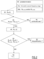
figure 2 is a flow chart of the process according to the invention; -
figure 3 is a detailed flow chart of the making of a decision whether to disqualify the battery according to one embodiment; -
figure 4 represents the internal resistance of a givenbattery 10 at a given date t as a function of the frequency at which the internal resistance is measured, the frequency being represented with a logarithmic scale, the resistance being measured at a temperature of 45°C for exemplary batteries A to H; and -
figure 5 represents the internal resistance of a givenbattery 10 at a given date t as a function of the frequency at which the internal resistance is measured, the frequency being represented with a logarithmic scale, the resistance being measured at a temperature of 25°C for exemplary batteries A, B and E to H. - The process of managing an
electrochemical battery 10 is intended to be carried out by a battery management system (hereafter designed as BMS) 15 integrated in theelectrochemical battery 10. - A typical
electrochemical battery 10 is represented onfigure 1 . - The
battery 10 is for example a Lithium-ion (Li-ion) battery. - The
battery 10 is for example adapted for use in a battery electric vehicle (not represented). - The
battery 10 comprises ahousing 20 in which a plurality ofelectrochemical cells 25 are stacked and each connected to theBMS 15, - The BMS 15 is configured to manage the performance and operation of the
battery 10. - By way of non-limitative examples, the
BMS 15 is configured to protect thebattery 10 from operating outside a predetermined working temperature range, and/or for monitoring the state of charge (SOC) of thebattery 10, and/or for calculating and/or reporting data to other control systems of an apparatus powered by thebattery 10. - The BMS 15 is also configured to control recharging of the
battery 10. - In reference to
figure 2 , a process of managing thebattery 10 with theBMS 15 according to the invention is described hereafter. - The process comprises a
first measurement step 30 at which at least one first internal resistance RHF(t) of thebattery 10 at a given date t at a first frequency f1 within a first frequency range is measured with impedance measurement means of theBMS 15. - Typically, the first frequency range is comprised in the interval [500 Hz, 100 kHz], preferably [500 Hz, 50 kHz], more preferably [500 Hz, 20 kHz].
- Preferably, the first frequency f1 is of the order of 1 kHz to 10 kHz.
- The measurement of the first internal resistance RHF(t) of the
battery 10 comprises the measurement of at least one internal resistance of the battery at the given date t at the first frequency f1. - Preferably, the measurement of the first internal resistance RHF(t) of the
battery 10 is performed at a first temperature θ1(t). - The first temperature θ1(t) is advantageously comprised between 15°C and 60°C, more preferably between 20°C and 50°C, even more preferably between 25°C and 45°C.
- As can be seen on
figure 4 , the inventors have observed that whatever the state of health, the internal resistance of a Li-ion battery 10 varies very slowly with the frequency in a low frequency range (typically [0,1 Hz, 10 Hz] for the batteries offigure 4 ), as well as in a high frequency range (typically [1 kHz, 10 kHz] for the batteries offigure 4 ), whereas it varies much faster with the frequency in a medium frequency range (typically [10 Hz, 1 kHz] for the batteries offigure 4 ). Consequently, the particular value of the first frequency f1 chosen within the first frequency range, being in the case offigure 4 the high frequency range, is of little importance for the rest of process in the case of Li-ion battery. - This appears even more clearly on
figure 5 , for which the measurements have been performed at a temperature of 25°C. - Optionally, in order to take into account the low variations of the internal resistance within the first frequency range, for example for other type of
batteries 10, a plurality of internal resistances of the battery at a plurality of first frequencies within the first frequency range and/or at a plurality of dates t within a predetermined measurement period T are performed. - In this case, the first internal resistance RHF(t) measured at
step 30 is a mean value of the plurality of internal resistances measured. - Then, the process comprises a
first comparison step 35 of the first internal resistance RHF(t) measured with a first reference internal resistance RHF,REF. - The
first comparison 35 is performed with a processor of theBMS 15. - The first reference internal resistance RHF,REF is a measured or expected internal resistance of the
battery 10 at the first frequency f1 before any use of thebattery 10. - In other words, the first reference internal resistance RHF,REF is a predetermined value representative of the internal resistance of the
battery 10 within the first frequency range, preferably at the first frequency f1, before ageing. - The first reference internal resistance RHF,REF is preferably representative of the internal resistance of the
battery 10 within the first frequency range, preferably at the first frequency f1, before ageing, preferably at the temperature θ1(t) of thebattery 10 at which the first internal resistance RHF(t) has been measured. - If the first internal resistance RHF(t) measured is considered as strictly higher than the first reference internal resistance RHF,REF, or equivalently if the difference between the ratio of the difference between first internal resistance RHF(t) and the first reference internal resistance RHF,REF and of the first reference internal resistance RHF,REF is higher than a first predetermined tolerance value TOL, the process comprises a
decision step 40 regarding whether to continue to use thebattery 10 or not. Otherwise, the process comprises asecond measurement step 45. - The TOL value is advantageously of less than 5%, preferably less than 2%, more preferably less than 1%.
- For example, the
decision step 40 comprises deciding to operate the battery without changes. - Optionally, if a continued use of the battery in the apparatus is decided, a fast charge and/or regeneration current intensity Ic of the
battery 10 for a subsequent charging step of thebattery 10, compared to an intensity of this charging current chosen before the measurement of the first internal resistance RHF(t), is increased, advantageously incrementally. - Indeed, the fact that the process results in
step 40 allows considering that the fast charge and/or regeneration current intensity Ic implemented by theBMS 15 prior to the process is not too high, as will be explained later. - At the
second measurement step 45, a second internal resistance RLF(t) of thebattery 10 at the given date t at a second frequency f2 within a second frequency range is measured with impedance measurement means of theBMS 15. - An upper frequency of the second frequency range is lower than a lower frequency of the first frequency range, such that the second frequency f2 is necessarily lower than the first frequency f1.
- Typically, the second frequency range is comprised in the interval [0.01 Hz, 50 Hz], preferably [0.05 Hz, 20 Hz], more preferably [0.07 Hz, 20 Hz].
- Preferably, the second frequency f2 is of the order of 0.1 Hz to 1 Hz.
- The measurement of the second internal resistance RLF(t) of the
battery 10 comprises the measurement of at least one internal resistance of the battery at the given date t at the second frequency f2. - Preferably, the measurement of the second internal resistance RLF(t) of the
battery 10 is performed at a second temperature θ2(t). - The second temperature θ2(t) is advantageously comprised between 15°C and 60°C, more preferably between 20°C and 50°C, even more preferably between 25°C and 45°C.
- The second temperature θ2(t) is advantageously equal to the first temperature θ1(t).
- As already explained and shown on
figure 4 , the inventors have observed that whatever the state of health, the internal resistance of a Li-ion battery 10 varies very slowly with the frequency in the low frequency range (typically [0,1 Hz, 10 Hz] for the batteries offigure 4 ). - Consequently, the particular value of the second frequency f2 chosen within the second frequency range, being in the case of
figure 4 the low frequency range, is of little importance for the rest of process in the case of Li-ion battery. - Optionally, in order to take into account the low variations of the internal resistance within the second frequency range, for example for other type of
batteries 10, a plurality of internal resistances of the battery at a plurality of second frequencies within the second frequency range and/or at a plurality of dates t within the predetermined measurement period T are performed. - In this case, the second internal resistance RLF(t) measured at
step 45 is a mean value of the plurality of internal resistances measured. - Optionally, the
first measurement step 30 and thesecond measurement step 45 are performed simultaneously. - Then, the process comprises a
second comparison step 50 of a difference D(t) = RLF(t) - RHF(t) between the measured second internal resistance RLF(t) and the measured first internal resistance RHF(t), with a reference difference DREF = RLF,REF - RHF,REF between a second reference internal resistance RLF,REF and the first reference internal resistance RHF,REF. - The
second comparison 50 is performed with the processor of theBMS 15. - The first reference internal resistance RHF,REF is a measured or expected internal resistance of the
battery 10 at the first frequency f1 before any use of thebattery 10. - In other words, the first reference internal resistance RHF,REF is a predetermined value representative of the internal resistance of the
battery 10 within the first frequency range, preferably at the first frequency f1, before ageing. - The second reference internal resistance RLF,REF is preferably representative of the internal resistance of the
battery 10 within the second frequency range, preferably at the second frequency f2, before ageing, preferably at the temperature θ2(t) of thebattery 10 at which the second internal resistance RLF(t) has been measured. - If the difference D(t) is considered as strictly higher than the reference difference DREF, or equivalently if the difference between the ratio of the difference between D(t) and DREF and of DREF is higher than a second predetermined tolerance value TOL2, the process comprises a
decision step 55 regarding whether to disqualify thebattery 10 or not. Otherwise, the process comprises areduction step 60. - As can be seen on
figure 4 , the difference D(t) is higher than the reference difference DREF measured for the new battery (examples G and H) in case a subsequent ageing is performed by either purely calendar ageing (examples C and D) or purely cycling ageing (examples E and F). - On the contrary, the difference D(t) is lower than the reference difference DREF measured for the new battery (examples G and H) in case a subsequent ageing is performed by Li-plating (examples A and B).
- This appears even more clearly on
figure 5 , for which the measurements have been performed at a temperature of 25°C. - Hence, without wishing to be bound by any theory, the inventors are of the opinion that the comparison of the difference D(t) with the reference difference DREF allows to discriminate between different types of ageing and in particular, to identify cases where the ageing is due to a too high charge current intensity.
- In case of Li-ion battery, a too high charge current intensity induces in particular Li plating of the electrodes that can be observed macroscopically.
- This example is given only for explanatory purposes, since many other physicochemical consequences of a high charge current intensity, either for Li-ion battery or for other type of battery, can lead to the reduction of the difference D(t) compared to the reference difference DREF.
- The
reduction step 60 comprises reducing an intensity Ic of a charge current either for a subsequent charge or a subsequent regeneration of thebattery 10, compared to the intensity implemented by theBMS 15 before thefirst measurement step 30. - The charge current can be a fast charge current, i.e., an electrical current supplied to the
battery 10 for its fast charging with a charger. - Alternatively or in addition, the charge current is a regeneration current, i.e., an electrical current supplied to the
battery 10 for its charging with a regenerative braking system of a battery electric vehicle, the vehicle being equipped with thebattery 10. - The fast charge current and/or the regeneration current is for example a pulsed current. The pulse with is for example comprised between 1s to 10s, preferably 2s to 10s.
- The reduction of the intensity Ic is for example incremental. In this case, each time the process is performed and results in a
reduction step 60, the intensity Ic is decreased of a predetermined percentage. - By way of an example, the predetermined percentage is 5%.
- This allows, in cases where the process according to the invention is iteratively performed, to progressively converge towards the optimal charge intensity Ic instead of a too drastic reduction.
- Since the observed reduction of the difference D(t) is considered as a consequence of an ageing process which is linked to a too high charge current intensity, and which is neither calendar ageing nor cycling ageing, such a reduction allows to limit premature ageing of the
battery 10 due to a charging management which is suboptimal with respect to ageing. - In some cases, this also prevents disqualification of the
battery 10 due to lack of discrimination between the different types of ageing processes. - If the
reduction step 60 is not performed, thedecision step 55 regarding whether to disqualify thebattery 10 or not is performed with the processor of theBMS 15. - The
decision step 55 comprises making a decision whether to disqualify thebattery 10 for equipping the apparatus or not. - For example, the
decision step 55 comprises deciding to continue the operation of thebattery 10 without changes. - In an alternative embodiment represented on
figure 3 , thedecision step 55 comprises anactualization step 551 at which the processor of theBMS 15 implementing a calendar ageing model calculates updated value RLF,REF,ACT of the second reference internal resistance RLF,REF. - For example, the processor receives a plurality of SOC-tuples from means for monitoring the state of charge SOC of the battery comprised in the
BMS 15. Each tuple SOC-tuple comprises a battery charge level and a battery temperature measured with the monitoring means at a given date t'. - Preferably, the dates t' are evenly distributed between a beginning of the use of the
battery 10 and the given date t at which thefirst measurement step 30 is performed. - Based on the tuples SOC-tuples, the processor of the
BMS 15 can determine the time spent by thebattery 10 at any level of charge comprises between 0% and 100% and any temperature comprised between a minimum temperature and a maximum temperature. - Thanks to the calendar ageing model receiving these data, the processor can thus determine the updated value RLF,REF,ACT, which represents an expected second reference internal resistance if no calendar had occurred.
- This is particularly advantageous since calendar ageing is associated with a significant increase in the difference D(t), which can hide a reduction of the difference D(t) due to a too high charge current intensity, even if the
second measurement step 45 has been performed. - This can be understood by comparing example A and D on
figure 4 . - The
decision step 55 then comprises athird comparison step 552, asecond reduction step 554 and adecision step 553 whether to keep thebattery 10 in operation to power the apparatus, which are analogous mutatis mutandis to respectively thesecond comparison step 50, thereduction step 60 and thedecision step 55 whether to disqualify thebattery 10 or not. - Optionally, the process comprises a
preliminary step 65 of determination for determining one or more predetermined values implemented in thefirst measurement step 30 and/or in thesecond measurement step 45 and/or in thefirst comparison step 35 and/or in thesecond comparison step 50 and/or in the decision regardingdisqualification step 55. - The
preliminary step 65 may comprise astep 65a for determining the first frequency range and/or of the second frequency range for thebattery 10. - For example, a reference battery representative of a type of electrochemical reaction occurring in the
battery 10 and/or of an architecture of thebattery 10 can be provided. - The internal resistance of the reference battery is then measured for a plurality of frequencies in the range [0 Hz, 100 kHz] at at least one predetermined temperature.
- Finally, a first and a second frequency range within which the internal resistance of the reference battery varies much less than within a third frequency range comprised between the first frequency range and the second frequency range are determined, the frequencies in the first frequency range being higher than the frequencies in the second frequency range.
- The
preliminary step 65 can comprise astep 65b for determining the first reference internal resistance RHF,REF and/or the second reference internal resistance RLF,REF. - For example, the first reference internal resistance RHF,REF of the
battery 10 is measured at at least one predetermined temperature at the first frequency f1 before any use of thebattery 10. - As a variant, the first reference internal resistance RHF,REF of the reference battery is measured at at least one predetermined temperature at the first frequency f1 before any use of the reference battery.
- Advantageously, the
preliminary step 65 comprises bothsteps - One understands that the process according to the invention allows to discriminate between calendar and cycling ageing processes and other ageing processes, and as a consequence to adapt the intensity of the charge current of the battery in case other ageing processes are observe.
- Consequently, the service life of the
battery 10 is increased compared to prior art processes and some premature disqualifications can be prevented. - Optionally, the steps of the process are periodically repeated. Advantageously, the first temperature θ1(t) and/or the second temperature θ2(t) are chosen at each repetition of the process according to the current use of the
battery 10. - The experiments of examples A to H were performed on identical Li-ion batteries comprising:
- a) an anode comprising :
- 97% by weight of a blend of natural and synthetic graphite;
- 1,5% by weight of a carboxymethyl cellulose (CMC) binder; and
- 1,5% by weight of a styrene-butadiene rubber (SBR) binder;
- b) a cathode of the NMC 811 type (Nickel 80 at% -
Manganèse 10 at% -Cobalt 10 at%); - c) a polyolefine based separator coated with Aluminum;
- d) an electrolyte comprising a LiPF6 salt dissolved in a ternary solvent mixture of ethylene carbonate (EC), dimethyl carbonate (DMC), diethyl carbonate (DEC) and ethyl methyl carbonate (EMC).
- The fast-charge ageing protocol used for examples A and B is designed to promote lithium metal deposition on the anode. The fast-charge ageing protocol comprises the following steps, performed in a climatic chamber at 25°C:
- a) perform a capacity control cycle ;
- b) have the battery rest for 10 min;
- c) charge the battery at a 1C rate until the battery voltage is equal to 4,2V and then float charge for 2 h at a charge rate of less than C/20;
- d) have the battery rest for 10 min;
- e) discharge the battery at a C/5 rate until the battery voltage is equal to 2,7V;
- f) have the battery rest for 10 min; and
- g) perform a capacity control cycle.
- The calendar storage ageing protocol used for examples C and D is designed to promote solid electrolyte interface (SEI) growth and cathode degradation. The calendar storage ageing protocol comprises the following steps, performed in a climatic chamber at 60°C:
- a) discharge the battery at 25°C in a climatic chamber at a C/10 rate until the battery voltage is equal to 2,7V;
- b) perform a capacity control cycle at 25°C in a climatic chamber;
- c) charge the battery at a C/10 rate until the battery voltage is equal to 4,2V and then float charge for 2 h at a charge rate of less than C/20 at 25°C in a climatic chamber;
- d) store the battery during 15 days in a climatic chamber at 60°C at 100% State of Charge (SOC) measured with the open circuit voltage (OCV) method.
- The cycling ageing protocol used for examples E and F is designed to promote promote ageing mechanisms associated with the full lithiation of delithiation of the different active materials. The cycling ageing protocol comprises the following steps, performed in a climatic chamber at 45°C:
- a) perform a capacity control cycle ;
- b) perform a resistance control cycle
- c) have the battery rest for 10 min;
- d) charge the battery at a C/3 rate until the battery voltage is equal to 4,2V and then float charge for 2 h at a charge rate of less than C/20;
- e) have the battery rest for 10 min;
- f) discharge the battery at a C/5 rate until the battery voltage is equal to 2,7V;
- g) have the battery rest for 10 min; and
- h) return to step d) for 50 cycles comprising d) to h) then go to step a) until a total of 500 cycles comprising d) to h).
Claims (11)
- A process of managing an electrochemical battery (10) by means of a battery management system (15), the process comprising:(a) measuring at least one first internal resistance (RHF(t)) of the battery at at least a first frequency (f1) within a first frequency range and comparing the measured first internal resistance (RHF(t)) with a first reference internal resistance (RHF,REF);(b1) if the first measured internal resistance (RHF(t)) is less than or equal to the first reference internal resistance (RHF,REF), making a decision regarding continued use of the battery (10); and otherwise(b2) measuring at least one second internal resistance (RLF(t)) of the battery at at least one second frequency (f2) in a second frequency range lower than the first frequency range, and comparing a difference D(t) between the measured second internal resistance (RLF(t)) and the measured first internal resistance (RHF(t)) with a reference difference (DREF) between a second reference internal resistance (RLF,REF) and the first reference internal resistance (RHF,REF); and(c1) if the difference D(t) is greater than or equal to the reference difference (DREF), making a decision regarding a disqualification of the battery (10); and otherwise(c2) reducing an intensity (Ic) of a fast charge and/or regeneration current for a subsequent charging step of the battery (10) compared to an intensity of this charging current chosen before the measurement of the first internal resistance (RHF(t)).
- Process of managing an electrochemical battery (10) according to claim 1, wherein the first frequency range is comprised in the interval [500 Hz, 100 kHz].
- Process of managing an electrochemical battery (10) according to claim 2, wherein the second frequency range is comprised in the interval [0.01 Hz; 50 Hz].
- Process of managing an electrochemical battery (10) according to claim 1, wherein if continued use of the battery (10) is decided at c1), the intensity (Ic) of a fast charge and/or regeneration current is increased, advantageously incrementally.
- Process of managing an electrochemical battery (10) according to any of the preceding claims, wherein the making of a decision regarding disqualification of the battery (10) comprises:(c1i) providing an updated value of the second reference internal resistance (RLF,REF,ACT) with a processor of the battery management system (15) implementing a calendar ageing model and receiving as input tuples (SOC-tuple), each representative of a state of charge (SOC) of the battery (10) at a given date, for at least two different dates prior to a date (t) on which the process is implemented; then(c1ii) comparing the difference D(t) between the measured second internal resistance (RLF(t)) and the measured first internal resistance (RHF(t)) with an updated difference (DACT(t)) between the updated value of second reference internal resistance (RLF,REF,ACT) and the first reference internal resistance (RHF,REF); and(c1ii) if the difference D(t) is greater than or equal to the updated reference difference, making a decision whether to keep the battery in operation; and if not(c2) deciding not to disqualify the battery (10) and to reduce the intensity (Ic) of a fast charge and/or regeneration current.
- Process of managing an electrochemical battery (10) according to any of the preceding claims, wherein the measurement of the first internal resistance (RHF(t)) and the measurement of the second internal resistance (RLF(t)) are performed simultaneously.
- Process of managing an electrochemical battery (10) according to any of the preceding claims, wherein the steps of the process are periodically repeated.
- Process of managing an electrochemical battery (10) according to claim 7, wherein the reduction of the intensity (Ic) of a fast charge and/or a regeneration courant is performed incrementally, preferably in a percentage of 5%.
- Process of managing an electrochemical battery (10) according to any of claims 7 and 8, wherein if a decision to increase the intensity (Ic) has been made and a step of charging the battery (10) with the increased intensity (Ic) has been performed, for a first iteration of the process performed after the charging step, only step (b2) and optionally (c1) and (c2) are performed.
- An electrochemical battery management system (15) comprising means adapted to perform the steps of the process according to any of the preceding claims.
- A computer program comprising instructions which cause an electrochemical battery management system (15) according to claim 10 to perform the process steps of any of claims 1 to 9.
Priority Applications (1)
| Application Number | Priority Date | Filing Date | Title |
|---|---|---|---|
| EP23307193.5A EP4571341A1 (en) | 2023-12-13 | 2023-12-13 | Process of managing an electrochemical battery and system for managing an electrochemical battery |
Applications Claiming Priority (1)
| Application Number | Priority Date | Filing Date | Title |
|---|---|---|---|
| EP23307193.5A EP4571341A1 (en) | 2023-12-13 | 2023-12-13 | Process of managing an electrochemical battery and system for managing an electrochemical battery |
Publications (1)
| Publication Number | Publication Date |
|---|---|
| EP4571341A1 true EP4571341A1 (en) | 2025-06-18 |
Family
ID=89386162
Family Applications (1)
| Application Number | Title | Priority Date | Filing Date |
|---|---|---|---|
| EP23307193.5A Pending EP4571341A1 (en) | 2023-12-13 | 2023-12-13 | Process of managing an electrochemical battery and system for managing an electrochemical battery |
Country Status (1)
| Country | Link |
|---|---|
| EP (1) | EP4571341A1 (en) |
Citations (3)
| Publication number | Priority date | Publication date | Assignee | Title |
|---|---|---|---|---|
| US4743855A (en) * | 1983-12-12 | 1988-05-10 | Randin Jean Paul | Method of and apparatus for measuring the state of discharge of a battery |
| US20160131719A1 (en) * | 2013-07-17 | 2016-05-12 | Yazaki Corporation | Battery state detection device |
| JP2022069223A (en) | 2020-10-23 | 2022-05-11 | 日新電機株式会社 | Storage battery system, deterioration judgment device and deterioration judgment method |
-
2023
- 2023-12-13 EP EP23307193.5A patent/EP4571341A1/en active Pending
Patent Citations (3)
| Publication number | Priority date | Publication date | Assignee | Title |
|---|---|---|---|---|
| US4743855A (en) * | 1983-12-12 | 1988-05-10 | Randin Jean Paul | Method of and apparatus for measuring the state of discharge of a battery |
| US20160131719A1 (en) * | 2013-07-17 | 2016-05-12 | Yazaki Corporation | Battery state detection device |
| JP2022069223A (en) | 2020-10-23 | 2022-05-11 | 日新電機株式会社 | Storage battery system, deterioration judgment device and deterioration judgment method |
Similar Documents
| Publication | Publication Date | Title |
|---|---|---|
| JP5687584B2 (en) | Lithium-ion battery condition measurement device | |
| KR102296993B1 (en) | Apparatus and Method for Estimating Resistance of Secondary Battery | |
| JP6176505B2 (en) | Battery system | |
| CN103314303B (en) | For measuring the method for the open-circuit voltage of accumulator, there is the accumulator of module for measuring open-circuit voltage and there is the motor vehicles of corresponding accumulator | |
| US20230335822A1 (en) | Method for charging power battery and battery management system | |
| KR20180068708A (en) | Method and apparatus for assessing lifetime of secondary battery | |
| KR101783918B1 (en) | Apparatus and Method for Estimating Resistance of Secondary Battery | |
| JP5699970B2 (en) | Lithium ion secondary battery system and deposition determination method | |
| KR20170023583A (en) | Detection method of Li plating, method and apparatus for charging secondary battery and secondary battery system using the same | |
| US11415637B2 (en) | System and method for estimating battery state of health | |
| KR20110053252A (en) | Charging method and charging device for nonaqueous electrolyte secondary battery | |
| US10605871B2 (en) | Method and device for determining state of rechargeable battery | |
| CN109088114A (en) | Battery modules charge/discharge control method | |
| EP4254714A1 (en) | Power battery charging method and battery management system | |
| JPWO2020044932A1 (en) | Rechargeable battery charging system | |
| US20230271523A1 (en) | Method for charging traction battery and battery management system | |
| Michelini et al. | Impact of Prolonged Electrochemical Cycling on Health Indicators of Aged Lithium-Ion Batteries for a Second-Life Use | |
| CN120222570B (en) | Method and device for determining battery charging multiplying power, electronic equipment and storage medium | |
| CN114977431A (en) | Lithium battery balance control method and system | |
| CN114879053A (en) | Method for predicting service life of energy storage lithium iron phosphate battery | |
| WO2024216024A1 (en) | Methods and systems for restoring lithium metal liquid-electrolyte electrochemical cells | |
| KR20200093228A (en) | Apparatus and method for calculating the state of charge of a lfp battery | |
| CN117647743A (en) | Methods, devices, equipment and storage media for determining battery capacity | |
| CN116799893A (en) | Charging current control method and device, electronic equipment, storage medium | |
| CN116014859B (en) | Charging method and system for inhibiting battery lithium precipitation under active detection and protection conditions |
Legal Events
| Date | Code | Title | Description |
|---|---|---|---|
| PUAI | Public reference made under article 153(3) epc to a published international application that has entered the european phase |
Free format text: ORIGINAL CODE: 0009012 |
|
| STAA | Information on the status of an ep patent application or granted ep patent |
Free format text: STATUS: THE APPLICATION HAS BEEN PUBLISHED |
|
| STAA | Information on the status of an ep patent application or granted ep patent |
Free format text: STATUS: REQUEST FOR EXAMINATION WAS MADE |
|
| AK | Designated contracting states |
Kind code of ref document: A1 Designated state(s): AL AT BE BG CH CY CZ DE DK EE ES FI FR GB GR HR HU IE IS IT LI LT LU LV MC ME MK MT NL NO PL PT RO RS SE SI SK SM TR |
|
| 17P | Request for examination filed |
Effective date: 20250611 |
|
| P01 | Opt-out of the competence of the unified patent court (upc) registered |
Free format text: CASE NUMBER: UPC_APP_2701_4571341/2025 Effective date: 20250807 |
|
| GRAP | Despatch of communication of intention to grant a patent |
Free format text: ORIGINAL CODE: EPIDOSNIGR1 |
|
| STAA | Information on the status of an ep patent application or granted ep patent |
Free format text: STATUS: GRANT OF PATENT IS INTENDED |
|
| GRAJ | Information related to disapproval of communication of intention to grant by the applicant or resumption of examination proceedings by the epo deleted |
Free format text: ORIGINAL CODE: EPIDOSDIGR1 |
|
| STAA | Information on the status of an ep patent application or granted ep patent |
Free format text: STATUS: REQUEST FOR EXAMINATION WAS MADE |
|
| RIC1 | Information provided on ipc code assigned before grant |
Ipc: G01R 31/392 20190101AFI20251103BHEP Ipc: H01M 10/42 20060101ALI20251103BHEP |
|
| INTG | Intention to grant announced |
Effective date: 20251117 |
|
| INTC | Intention to grant announced (deleted) | ||
| GRAP | Despatch of communication of intention to grant a patent |
Free format text: ORIGINAL CODE: EPIDOSNIGR1 |
|
| STAA | Information on the status of an ep patent application or granted ep patent |
Free format text: STATUS: GRANT OF PATENT IS INTENDED |
|
| INTG | Intention to grant announced |
Effective date: 20260114 |
|
| GRAS | Grant fee paid |
Free format text: ORIGINAL CODE: EPIDOSNIGR3 |
|
| GRAA | (expected) grant |
Free format text: ORIGINAL CODE: 0009210 |
|
| STAA | Information on the status of an ep patent application or granted ep patent |
Free format text: STATUS: THE PATENT HAS BEEN GRANTED |