EP4571317A1 - Parts management system, automatic analyzer, and parts management method - Google Patents
Parts management system, automatic analyzer, and parts management method Download PDFInfo
- Publication number
- EP4571317A1 EP4571317A1 EP23848580.9A EP23848580A EP4571317A1 EP 4571317 A1 EP4571317 A1 EP 4571317A1 EP 23848580 A EP23848580 A EP 23848580A EP 4571317 A1 EP4571317 A1 EP 4571317A1
- Authority
- EP
- European Patent Office
- Prior art keywords
- state information
- replacement
- information
- management system
- automatic analyzer
- Prior art date
- Legal status (The legal status is an assumption and is not a legal conclusion. Google has not performed a legal analysis and makes no representation as to the accuracy of the status listed.)
- Pending
Links
Images




Classifications
-
- G—PHYSICS
- G16—INFORMATION AND COMMUNICATION TECHNOLOGY [ICT] SPECIALLY ADAPTED FOR SPECIFIC APPLICATION FIELDS
- G16H—HEALTHCARE INFORMATICS, i.e. INFORMATION AND COMMUNICATION TECHNOLOGY [ICT] SPECIALLY ADAPTED FOR THE HANDLING OR PROCESSING OF MEDICAL OR HEALTHCARE DATA
- G16H10/00—ICT specially adapted for the handling or processing of patient-related medical or healthcare data
- G16H10/40—ICT specially adapted for the handling or processing of patient-related medical or healthcare data for data related to laboratory analysis, e.g. patient specimen analysis
-
- G—PHYSICS
- G01—MEASURING; TESTING
- G01N—INVESTIGATING OR ANALYSING MATERIALS BY DETERMINING THEIR CHEMICAL OR PHYSICAL PROPERTIES
- G01N35/00—Automatic analysis not limited to methods or materials provided for in any single one of groups G01N1/00 - G01N33/00; Handling materials therefor
- G01N35/00584—Control arrangements for automatic analysers
- G01N35/00594—Quality control, including calibration or testing of components of the analyser
- G01N35/00613—Quality control
- G01N35/00663—Quality control of consumables
-
- G—PHYSICS
- G01—MEASURING; TESTING
- G01N—INVESTIGATING OR ANALYSING MATERIALS BY DETERMINING THEIR CHEMICAL OR PHYSICAL PROPERTIES
- G01N35/00—Automatic analysis not limited to methods or materials provided for in any single one of groups G01N1/00 - G01N33/00; Handling materials therefor
- G01N35/00584—Control arrangements for automatic analysers
- G01N35/00722—Communications; Identification
- G01N35/00732—Identification of carriers, materials or components in automatic analysers
-
- G—PHYSICS
- G01—MEASURING; TESTING
- G01N—INVESTIGATING OR ANALYSING MATERIALS BY DETERMINING THEIR CHEMICAL OR PHYSICAL PROPERTIES
- G01N35/00—Automatic analysis not limited to methods or materials provided for in any single one of groups G01N1/00 - G01N33/00; Handling materials therefor
- G01N35/00584—Control arrangements for automatic analysers
- G01N35/00722—Communications; Identification
- G01N35/00871—Communications between instruments or with remote terminals
-
- G—PHYSICS
- G06—COMPUTING OR CALCULATING; COUNTING
- G06Q—INFORMATION AND COMMUNICATION TECHNOLOGY [ICT] SPECIALLY ADAPTED FOR ADMINISTRATIVE, COMMERCIAL, FINANCIAL, MANAGERIAL OR SUPERVISORY PURPOSES; SYSTEMS OR METHODS SPECIALLY ADAPTED FOR ADMINISTRATIVE, COMMERCIAL, FINANCIAL, MANAGERIAL OR SUPERVISORY PURPOSES, NOT OTHERWISE PROVIDED FOR
- G06Q10/00—Administration; Management
- G06Q10/06—Resources, workflows, human or project management; Enterprise or organisation planning; Enterprise or organisation modelling
- G06Q10/063—Operations research, analysis or management
-
- G—PHYSICS
- G06—COMPUTING OR CALCULATING; COUNTING
- G06Q—INFORMATION AND COMMUNICATION TECHNOLOGY [ICT] SPECIALLY ADAPTED FOR ADMINISTRATIVE, COMMERCIAL, FINANCIAL, MANAGERIAL OR SUPERVISORY PURPOSES; SYSTEMS OR METHODS SPECIALLY ADAPTED FOR ADMINISTRATIVE, COMMERCIAL, FINANCIAL, MANAGERIAL OR SUPERVISORY PURPOSES, NOT OTHERWISE PROVIDED FOR
- G06Q10/00—Administration; Management
- G06Q10/08—Logistics, e.g. warehousing, loading or distribution; Inventory or stock management
- G06Q10/087—Inventory or stock management, e.g. order filling, procurement or balancing against orders
- G06Q10/0875—Itemisation or classification of parts, supplies or services, e.g. bill of materials
-
- G—PHYSICS
- G06—COMPUTING OR CALCULATING; COUNTING
- G06Q—INFORMATION AND COMMUNICATION TECHNOLOGY [ICT] SPECIALLY ADAPTED FOR ADMINISTRATIVE, COMMERCIAL, FINANCIAL, MANAGERIAL OR SUPERVISORY PURPOSES; SYSTEMS OR METHODS SPECIALLY ADAPTED FOR ADMINISTRATIVE, COMMERCIAL, FINANCIAL, MANAGERIAL OR SUPERVISORY PURPOSES, NOT OTHERWISE PROVIDED FOR
- G06Q10/00—Administration; Management
- G06Q10/20—Administration of product repair or maintenance
-
- G—PHYSICS
- G06—COMPUTING OR CALCULATING; COUNTING
- G06Q—INFORMATION AND COMMUNICATION TECHNOLOGY [ICT] SPECIALLY ADAPTED FOR ADMINISTRATIVE, COMMERCIAL, FINANCIAL, MANAGERIAL OR SUPERVISORY PURPOSES; SYSTEMS OR METHODS SPECIALLY ADAPTED FOR ADMINISTRATIVE, COMMERCIAL, FINANCIAL, MANAGERIAL OR SUPERVISORY PURPOSES, NOT OTHERWISE PROVIDED FOR
- G06Q50/00—Information and communication technology [ICT] specially adapted for implementation of business processes of specific business sectors, e.g. utilities or tourism
- G06Q50/40—Business processes related to the transportation industry
-
- G—PHYSICS
- G16—INFORMATION AND COMMUNICATION TECHNOLOGY [ICT] SPECIALLY ADAPTED FOR SPECIFIC APPLICATION FIELDS
- G16H—HEALTHCARE INFORMATICS, i.e. INFORMATION AND COMMUNICATION TECHNOLOGY [ICT] SPECIALLY ADAPTED FOR THE HANDLING OR PROCESSING OF MEDICAL OR HEALTHCARE DATA
- G16H40/00—ICT specially adapted for the management or administration of healthcare resources or facilities; ICT specially adapted for the management or operation of medical equipment or devices
- G16H40/40—ICT specially adapted for the management or administration of healthcare resources or facilities; ICT specially adapted for the management or operation of medical equipment or devices for the management of medical equipment or devices, e.g. scheduling maintenance or upgrades
-
- G—PHYSICS
- G01—MEASURING; TESTING
- G01N—INVESTIGATING OR ANALYSING MATERIALS BY DETERMINING THEIR CHEMICAL OR PHYSICAL PROPERTIES
- G01N35/00—Automatic analysis not limited to methods or materials provided for in any single one of groups G01N1/00 - G01N33/00; Handling materials therefor
- G01N35/00584—Control arrangements for automatic analysers
- G01N35/00722—Communications; Identification
- G01N2035/00891—Displaying information to the operator
- G01N2035/0091—GUI [graphical user interfaces]
-
- G—PHYSICS
- G01—MEASURING; TESTING
- G01N—INVESTIGATING OR ANALYSING MATERIALS BY DETERMINING THEIR CHEMICAL OR PHYSICAL PROPERTIES
- G01N30/00—Investigating or analysing materials by separation into components using adsorption, absorption or similar phenomena or using ion-exchange, e.g. chromatography or field flow fractionation
- G01N30/02—Column chromatography
- G01N30/88—Integrated analysis systems specially adapted therefor, not covered by a single one of the groups G01N30/04 - G01N30/86
-
- G—PHYSICS
- G01—MEASURING; TESTING
- G01N—INVESTIGATING OR ANALYSING MATERIALS BY DETERMINING THEIR CHEMICAL OR PHYSICAL PROPERTIES
- G01N35/00—Automatic analysis not limited to methods or materials provided for in any single one of groups G01N1/00 - G01N33/00; Handling materials therefor
- G01N35/00584—Control arrangements for automatic analysers
Definitions
- the present invention relates to a part management system, an automatic analyzer, and a part management method.
- Patent Literature 1 discloses a chromatography system that can analyze a sample under a plurality of analysis conditions.
- the chromatography system includes an apparatus body having a flow channel for passing a liquid sample, an analysis column disposed in the middle of the flow channel and configured to separate the sample into a plurality of components, a replaceable part attached to the apparatus body, and a storage unit storing first position information about an attachment position of the part to the apparatus body.
- an attachment position of a part and a name and a lot number of the part are stored in association with each other in a storage unit, and even when the same type of part is used in a plurality of uses or positions, attachment position information can be acquired by inputting a name or lot number of a part to be removed at the time of part replacement.
- an object of the invention is to provide a part management system, an automatic analyzer, and a part management method capable of supporting specification of a part to be removed even when the same type of part is used in a plurality of uses or positions.
- the invention includes a plurality of means to solve the above problems, and an example thereof is a part management system for managing a plurality of parts used in an apparatus, the part management system including: a display unit that displays information about the part management system; a storage unit that stores, for each of the plurality of parts, an ID of the corresponding part and state information indicating a state of the part, the ID and the state information being stored in association with each other; a reception unit that receives a replacement request for the part; and a control unit that, when the reception unit receives a replacement request for the part, causes the display unit to display an ID of the part whose state information satisfies a predetermined requirement, and first state information about a position where the part is used.
- FIGS. 1 to 9 An embodiment of a part management system, an automatic analyzer, and a part management method according to the invention will be described with reference to FIGS. 1 to 9 .
- components also including element steps and the like
- components are not necessarily essential unless otherwise specified or unless clearly considered to be essential in principle.
- the same or corresponding components are denoted by the same or similar reference signs, and repeated description of these components may be omitted.
- FIG. 1 illustrates an overall configuration of the part management system according to the embodiment.
- an apparatus is an automatic analyzer 20 that measures physical properties of a biological sample and a part is two or more analysis devices 25 used for the measurement of the physical properties
- a target part of the part management system and the part management method according to the invention is not limited to an automatic analyzer.
- a part management system 1 according to the invention illustrated in FIG. 1 is a system that manages a plurality of analysis devices 25 used in the automatic analyzer 20, and includes a part management apparatus 10, the automatic analyzer 20, a management server 30, and a part center 40.
- the part management apparatus 10 and the automatic analyzer 20, the automatic analyzer 20 and the management server 30, and the management server 30 and the part center 40 can communicate with each other with priority or wirelessly.
- automatic analyzer 20 Although only one automatic analyzer 20 is shown, a plurality of automatic analyzers 20 may be provided.
- the part management apparatus 10 includes a part management apparatus control unit 11, an ID tag read unit 12, an input unit 13, a display unit 14, and a part management apparatus communication unit 15, and is implemented by, for example, a portable personal computer owned by a service engineer of a manufacturer of the automatic analyzer 20 or the like in the embodiment.
- the part management apparatus control unit 11 includes a CPU, a RAM, and a ROM, and can load a program stored in the ROM into the RAM and execute the program. For example, part record management described later that is performed in a constituent part database 24 of the automatic analyzer 20 at the time of part replacement is executed according to a program of the part management apparatus control unit 11.
- the part management apparatus control unit 11 is connected to other units, and can exchange data with the other units and relay data between the units. For example, information about an ID tag read by the ID tag read unit 12 is displayed on the display unit 14.
- the part management apparatus control unit 11 when the input unit 13 receives a replacement request for the analysis device 25, the part management apparatus control unit 11 causes the display unit 14 to display an ID of the analysis device 25 whose state information satisfies a predetermined requirement and first state information about a position where the analysis device 25 is used.
- the predetermined requirement may be a state ("state 3") in which preparation of a replacement product of the analysis device 25 is completed and the replacement is ready to be implemented. Details thereof will be described later.
- the ID tag read unit 12 is a reading device for reading an ID tag attached to the analysis device 25 or a packaging material of the analysis device 25, and can output information read from the ID tag to the part management apparatus control unit 11.
- the input unit 13 includes, in addition to an input device such as a keyboard and a mouse, a scanner that performs ID reading of the analysis device 25 to be replaced, and can transmit an input of a user to the part management apparatus control unit 11. In the embodiment, the input unit 13 receives a replacement request for the analysis device 25.
- the display unit 14 is a display such as a liquid crystal display, and can display information about the part management system 1 that is transmitted from the part management apparatus control unit 11.
- the display unit 14 may be a touch panel type to serve as a part of the input unit 13.
- the part management apparatus communication unit 15 can communicate with an automatic analyzer communication unit 22.
- the part management apparatus communication unit 15 communicates with the automatic analyzer 20 to acquire information in the constituent part database 24 of the automatic analyzer 20.
- the automatic analyzer 20 is an apparatus for causing a sample and a reagent to react with each other and measuring physical properties of a reacted reaction liquid, and includes an automatic analyzer control unit 21, an automatic analyzer storage unit 23 including the constituent part database 24, the automatic analyzer communication unit 22, and two or more analysis devices 25 used for measuring physical properties of a biological sample.
- a detailed configuration of the automatic analyzer 20 is not particularly limited, and may be various configurations such as a configuration in a single module, a configuration in a plurality of modules, a configuration in which a plurality of modules are coupled by a transport line or the like, and is not particularly limited.
- the automatic analyzer control unit 21 includes a CPU, a RAM, and a ROM, and can load a program stored in the ROM into the RAM and execute the program.
- the automatic analyzer control unit 21 is connected to other units, and can exchange data with the other units and relay data between the units.
- the automatic analyzer storage unit 23 is implemented by a storage medium such as a flash memory.
- the automatic analyzer storage unit 23 includes the constituent part database 24 that records information about one part (the analysis device 25) as one record.
- the automatic analyzer storage unit 23 stores an ID of the corresponding analysis device 25 and state information indicating a state of the analysis device 25, the ID and the state information being stored in association with each other.
- FIG. 2 illustrates an example of a data structure recorded in a part record in the constituent part database 24.
- part information a "part name” indicating name information of a part, a “part ID” indicating ID information for specifying a type of the part, a "use or position” indicating use position information of the part in an apparatus, a "status” indicating state information of the part, a “lot number” indicating lot information of the part, a “replacement type” indicating replacement type information of the part, an "insertion date and time” indicating time information about a time when the part is assembled into the apparatus, an “replacement interval” indicating number-of-day information about how many days the part can be used are recorded.
- the "part name” and the “part ID” of all the parts corresponding to higher hierarchies of the part are basically recorded in a descending order from a part having the highest hierarchy.
- the use position of the part can be distinguished by recording, as information of one hierarchy, detailed position information of the use position in place of the "part name” and ID information indicating the use position in place of the "part ID”.
- the state information of a part includes "state 1 (second state information)" of a state in which a part is normally assembled into an apparatus and the part is normally operating, “state 2 (third state information)” of a state in which a part assembled in the apparatus needs to be replaced and waits for a part arrangement, “state 3 (first state information)” of a state in which a part arrangement is completed and part replacement is possible, and “state 4 (fourth state information)” of a state in which a part is removed by part replacement and is not currently assembled into the apparatus.
- the lot information of a part records the lot number assigned when the part is shipped.
- apparatus installation information apparatus ID information and installation location information
- the replacement type information of a part records two part replacement reasons, that is, "periodic” indicating a periodic replacement and “failure” indicating a failure replacement. Since the failure replacement is more urgent, it is effective in a case where the priority of replacement is determined by the influence of an inventory status of the part or the like.
- the recording of the replacement type information is useful also at the time of information collection, which investigates a relationship between a service life of the part and an environment at a customer site.
- the time information about a time when a part is assembled into an apparatus and the number-of-day information about how many days a part can be used can be used as information for determining whether a periodic replacement of a part is necessary. For example, when "insertion date and time” + “replacement interval” - "current date and time” ⁇ "notified recommended number-of-day for part replacement", a periodic replacement of the part is necessary.
- the automatic analyzer communication unit 22 can communicate with a management server communication unit 35. For example, information in the constituent part database 24 of the automatic analyzer 20 is transmitted to the management server 30.
- the management server 30 includes a management server control unit 31, a management server storage unit 32 including the constituent part database 33, an analysis unit 34, and the management server communication unit 35.
- the management server control unit 31 includes a CPU, a RAM, and a ROM, and can load a program stored in the ROM into the RAM and execute the program.
- the management server control unit 31 is connected to other units, and can exchange data with the other units and relay data between the units.
- the management server storage unit 32 includes a recording medium such as a flash memory, and the management server storage unit 32 includes the constituent part database 33 similarly to the automatic analyzer 20. Since information recorded in the constituent part databases 24 of the automatic analyzers 20 operating at all the customer sites is aggregated in the constituent part database 33 of the management server 30, it is possible to confirm information about all the constituent parts (the analysis devices 25) of the automatic analyzers 20 from the constituent part database 33 of the management server 30.
- the constituent part database 33 of the management server 30 may record information necessary for using the aggregated information, such as the apparatus installation information described above.
- the analysis unit 34 can analyze information received from the management server control unit 31 and transmit a result to the management server control unit 31.
- the analysis unit 34 receives information of the constituent part database 33, analyzes whether there is a part requiring a replacement arrangement, such as a part that satisfies an "insertion date” + the "replacement interval” - the “current date and time” ⁇ the "notified recommended number-of-day for part replacement” and has the "status" of state 1, and transmits a result to the management server control unit 31.
- the management server communication unit 35 can communicate with the automatic analyzer communication unit 22 of the automatic analyzer 20 and a part center communication unit 41 of the part center 40. For example, the management server communication unit 35 acquires the information of the constituent part database 24 of the automatic analyzer 20.
- the part center 40 includes the part center communication unit 41 and an ID tag creation unit 42.
- the part center communication unit 41 can communicate with the management server communication unit 35.
- part center communication unit 41 receives a part arrangement request from the management server 30.
- the ID tag creation unit 42 creates a label including an ID tag to be attached to a packaging box of the analysis device 25 or the analysis device 25 when transporting the analysis device 25 for replacement.
- two types of information are recorded in the ID tag.
- the first type of information is information for specifying a removal part from the constituent part database 24 of the automatic analyzer 20 at the time of part replacement.
- the information corresponds to the "part ID”.
- the second type of information is information for generating a record of an assembling part at the time of part replacement.
- generating a record of an assembling part basically, there are many pieces of information that can be recorded without information acquisition from the outside, based on a reference to the record information of the removal part and an input of a default value.
- the state information can always be recorded as "state 1".
- the ID tag records the "part ID” and the "lot number” for the above reason. Regarding these types of information, the information to be recorded can be changed according to a use case.
- the "part name” and the "replacement interval” can be basically acquired from the record of the removal part, and normally, the information is not recorded in the ID tag.
- an ID tag size depends on performance of a reading device of the ID tag read unit 12 of the part management apparatus and the amount of information recorded in the ID tag, and the ID tag size increases as the amount of information increases. Therefore, when the amount of information to be recorded is large, the use of attaching an ID tag to a part is difficult.
- the ID tag since the ID tag is required when managing the record information in the constituent part database 24 at the time of part replacement, it is desirable to attach the ID tag to the analysis device 25, and store in an external storage unit (constituent part database 24 or 33), and the ID tag may be attached only to a packaging box.
- FIG. 3 illustrates an interface between part management systems in the embodiment until a part, which is assembled in the automatic analyzer 20 and operates normally, is removed by replacement.
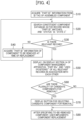
- FIG. 4 illustrates a processing procedure of the part management apparatus 10 at the time of part replacement in the step of (8) described above.
- the ID tag read unit 12 of the part management apparatus 10 acquires information recorded by an ID tag attached to a packaging box of a part to be assembled into an apparatus by replacement (S10).
- the part management apparatus 10 determines whether there is a record that satisfies a requirement (S30). When it is determined that a record satisfying a retrieval requirement is present in the constituent part database 24 of the automatic analyzer 20, the process proceeds to step S50.
- the removal part cannot be specified based on the "part ID" of the assembling part.
- the removal part needs to be specified by another method.
- the user manually inputs the "part ID” of the removal part.
- a change history of the "part ID” is recorded in the management server 30, and when the "part ID” of the assembling part is not in the constituent part database 24, the "part ID” coincident with that of the removal part before the change is acquired from the management server 30.
- the "part ID" of the part to be removed is acquired by these methods (S40), and the information is used to perform the retrieval again in the constituent part database 24 of the automatic analyzer 20 (S20), and the removal part is specified.
- the part management apparatus 10 displays the "part ID” and the "use or position" information of all the records satisfying the requirements in association with each other on the display unit 14 (S50).
- step S60 the user determines whether there are a plurality of parts that are removal candidates displayed on the display unit 14 in the preceding step S50 (S60).
- the part to be removed from the automatic analyzer 20 by replacement can be specified, and thus the process proceeds to step S80.
- FIG. 5 is a diagram illustrating an example of the record information
- FIG. 6 is a diagram illustrating an example of display of the display unit.
- a motor X (2) whose "status” is “state 1" and a motor X (3) whose "status” is “state 4" are not removal part candidates, and therefore are not displayed on the display unit 14.
- a specification screen 14A is displayed on the display unit 14.
- a part ID "0000001” in “use or position 1" and an “analyzer A” that is position information thereof, a part ID “0000002” in “use or position 2" and an “analysis unit A” that is position information thereof, a part ID “0000003” in “use or position 1” and a “drive unit A” that is position information thereof, a part ID “0000005" in “use or position 1” and a "motor A set” that is position information thereof, a part ID “0000006” of the "motor X” that is the corresponding analysis device 25 and the part name "motor X", and position information "SP1" are displayed so that the position can be specified step by step from the largest frame as illustrated in FIG. 6 . Accordingly, the user can easily specify an attachment position of the removal candidate part.
- FIG. 7 is a diagram illustrating an example of record information in a case where there are a plurality of removal part candidates.
- FIG. 8 is a diagram illustrating an example of display of the display unit in the case where there are a plurality of removal part candidates.
- the motor X (3) whose "status" is state 4 is not a removal part candidate, and therefore is not displayed on the display unit 14.
- the "use or position” is displayed in association with the "part ID", and thus the user can distinguish among removal candidate parts based on a difference in use position.
- a check box 14a is provided on the left side of the "part ID" of the removal candidate part, and the part to be removed can be specified by the user's selection.
- the ID tag when an ID tag is directly attached to a part having a higher hierarchy, the ID tag is read and thus the removal candidate part can be limited to parts whose "part ID" same as the ID tag are included in the "use or position".
- the "part ID" and the "use or position" in the record of the removal part specified by a method similar to that in FIG. 6 or FIG. 8 are displayed on the display unit 14 in association with each other, so that a support screen presenting a replacement position to the user is set.
- the state information of the removal part at the time of part replacement being "state 3" is used for specifying the removal part.
- the state information of the removal part is not necessarily "state 3".
- the part management apparatus control unit 11 causes the display unit 14 to display, on a selection screen 14B, one or more of the ID of the analysis device 25 in "state 1" in which the analysis device 25 is normally assembled and the second state information about a position where the analysis device 25 is used, and the ID of the analysis device 25 in "state 2" for waiting for the arrangement of the analysis device 25 and the third state information about a position where the analysis device 25 is used.
- part management apparatus control unit 11 hides and does not display, on the display unit 14, the ID of the analysis device 25 that is already not assembled in the apparatus and the fourth state information indicating the position where the analysis device 25 is used.
- the part management system 1 includes the part management apparatus 10, the automatic analyzer 20, the management server 30, and the part center 40 is described.
- the automatic analyzer 20 may include one or more configurations of the part management apparatus 10 or the management server 30, and the automatic analyzer 20 may be a separate apparatus.
- the automatic analyzer may include: two or more analysis devices 25 used for measurement of physical properties; a display unit 25a that displays information about the automatic analyzer; the automatic analyzer storage unit 23 that stores, for each of the plurality of analysis devices 25, an ID of the corresponding analysis device 25 and state information indicating a state of the analysis device 25, the ID and the state information being stored in association with each other; an input unit 25b that receives a replacement request for the analysis device 25; and the automatic analyzer control unit 21 that, when the input unit 25b receives a replacement request for the analysis device 25, causes the display unit 25a to display the ID of the analysis device 25 whose state information satisfies a predetermined requirement and first state information about a position where the analysis device 25 is used.
- the part management system 1 for managing a plurality of analysis devices 25 used in an apparatus includes: the display unit 14 that displays information about the part management system 1; the automatic analyzer storage unit 23 that stores, for each of the plurality of analysis devices 25, an ID of the corresponding analysis device 25 and state information indicating a state of the analysis device 25, the ID and the state information being stored in association with each other; the input unit 13 that receives a replacement request for the analysis device 25; and the part management apparatus control unit 11 that, when the input unit 13 receives a replacement request for the analysis device 25, causes the display unit 14 to display the ID of the analysis device 25 whose state information satisfies a predetermined requirement and first state information about a position where the analysis device 25 is used.
- Such a part that can be managed by the part management system 1 is not limited to the analysis device 25 of the automatic analyzer 20 used in clinical test, and can be applied to various multifunction devices in which constituent parts change due to replacement of consumable parts, repair, and the like, such as devices on ships and aircrafts used in the field of transportation and machine tools used in manufacturing and processing parts, and efficient management of constituent parts can be achieved.
- the predetermined requirement is a state where preparation of a replacement product of the analysis device 25 is completed and the replacement is ready to be implemented, information about the part that the replacement work can be started immediately can be displayed, and thus it is possible to implement display that is more easily understood by the user.
- the part management apparatus control unit 11 causes the display unit 14 to display one or more of the ID of the analysis device 25 in a state in which the analysis device 25 is normally assembled and second state information about a position where the analysis device 25 is used, and the ID of the analysis device 25 in a state of waiting for an arrangement of the analysis device 25 and third state information about a position where the analysis device 25 is used. Accordingly, states at other positions can be grasped, and replacement positions can be easily grasped even in a case of replacing a kit product that is sold with a plurality of types of parts collectively or replacing a part that is sold with other parts of the same type.
- the second state information is updated to the third state information. Accordingly, it is possible to automatically arrange a replacement part without requiring the user to update the information, and it is possible to restrict an occurrence of missed and delayed replacement, and the like.
- the third state information is updated to the first state information. Accordingly, it is unnecessary for the user to update the information, and a further reduction in burden can be achieved.
- the first state information is updated to the fourth state information. Accordingly, it is unnecessary for the user to update the information, and since unnecessary information is prevented from being displayed, it is easier for the user to grasp only necessary information.
Landscapes
- Business, Economics & Management (AREA)
- Engineering & Computer Science (AREA)
- Health & Medical Sciences (AREA)
- General Physics & Mathematics (AREA)
- Human Resources & Organizations (AREA)
- Physics & Mathematics (AREA)
- General Health & Medical Sciences (AREA)
- Economics (AREA)
- General Business, Economics & Management (AREA)
- Strategic Management (AREA)
- Quality & Reliability (AREA)
- Theoretical Computer Science (AREA)
- Marketing (AREA)
- Entrepreneurship & Innovation (AREA)
- Tourism & Hospitality (AREA)
- Life Sciences & Earth Sciences (AREA)
- Operations Research (AREA)
- Pathology (AREA)
- Immunology (AREA)
- Biochemistry (AREA)
- Analytical Chemistry (AREA)
- Chemical & Material Sciences (AREA)
- Primary Health Care (AREA)
- Public Health (AREA)
- Medical Informatics (AREA)
- Epidemiology (AREA)
- Development Economics (AREA)
- Biomedical Technology (AREA)
- Game Theory and Decision Science (AREA)
- Educational Administration (AREA)
- Accounting & Taxation (AREA)
- Finance (AREA)
- Automatic Analysis And Handling Materials Therefor (AREA)
- Management, Administration, Business Operations System, And Electronic Commerce (AREA)
Abstract
Description
- The present invention relates to a part management system, an automatic analyzer, and a part management method.
-
Patent Literature 1 discloses a chromatography system that can analyze a sample under a plurality of analysis conditions. The chromatography system includes an apparatus body having a flow channel for passing a liquid sample, an analysis column disposed in the middle of the flow channel and configured to separate the sample into a plurality of components, a replaceable part attached to the apparatus body, and a storage unit storing first position information about an attachment position of the part to the apparatus body. - PTL 1:
WO2020/183760 - In the above-described technique in the related art, an attachment position of a part and a name and a lot number of the part are stored in association with each other in a storage unit, and even when the same type of part is used in a plurality of uses or positions, attachment position information can be acquired by inputting a name or lot number of a part to be removed at the time of part replacement.
- However, in a case where a part used in a plurality of uses or positions is to be replaced due to a failure or the like only by retrieval according to a name or lot number of the part, it is difficult to specify an actual replacement target part from removal candidate parts satisfying a retrieval requirement, and there is room for improvement.
- In order to manage a replacement record of parts of an apparatus, even when the same type of part is used in a plurality of uses or positions in the apparatus, at the time of part replacement, it is necessary to specify one of the uses or positions of the part that needs to be removed for replacement, and to perform replacement and recording accurately.
- Therefore, an object of the invention is to provide a part management system, an automatic analyzer, and a part management method capable of supporting specification of a part to be removed even when the same type of part is used in a plurality of uses or positions.
- The invention includes a plurality of means to solve the above problems, and an example thereof is a part management system for managing a plurality of parts used in an apparatus, the part management system including: a display unit that displays information about the part management system; a storage unit that stores, for each of the plurality of parts, an ID of the corresponding part and state information indicating a state of the part, the ID and the state information being stored in association with each other; a reception unit that receives a replacement request for the part; and a control unit that, when the reception unit receives a replacement request for the part, causes the display unit to display an ID of the part whose state information satisfies a predetermined requirement, and first state information about a position where the part is used.
- According to the invention, even when the same type of part is used in a plurality of uses or positions, it is possible to support specification of a part to be removed. Problems, configurations, and effects other than those described above will become apparent in the following description of embodiments.
-
- [
FIG. 1] FIG. 1 is a diagram illustrating overall configuration of a part management system according to an embodiment. - [
FIG. 2] FIG. 2 is a table illustrating an example of a data structure of a constituent part database in the part management system according to the embodiment. - [
FIG. 3] FIG. 3 is a diagram illustrating an example of interfaces between part management systems in the part management system according to the embodiment. - [
FIG. 4] FIG. 4 is a flowchart illustrating a processing procedure of a part management apparatus at a time of part replacement in the part management system according to the embodiment. - [
FIG. 5] FIG. 5 is a diagram illustrating an example of record information in the part management system according to the embodiment. - [
FIG. 6] FIG. 6 is a diagram illustrating an example of display of a display unit in the part management system according to the embodiment. - [
FIG. 7] FIG. 7 is a diagram illustrating an example of the record information in a case where there are a plurality of removal part candidates in the part management system according to the embodiment. - [
FIG. 8] FIG. 8 is a diagram illustrating an example of display of the display unit in a case where there are a plurality of removal part candidates in the part management system according to the embodiment. - [
FIG. 9] FIG. 9 is a diagram illustrating an example of a screen for selecting state information to be displayed in the part management system according to the embodiment. - An embodiment of a part management system, an automatic analyzer, and a part management method according to the invention will be described with reference to
FIGS. 1 to 9 . In the following embodiment, it is needless to mention that components (also including element steps and the like) thereof are not necessarily essential unless otherwise specified or unless clearly considered to be essential in principle. In the drawings used in the description, the same or corresponding components are denoted by the same or similar reference signs, and repeated description of these components may be omitted. - First, an overall configuration of a part management system will be described with reference to
FIG. 1. FIG. 1 illustrates an overall configuration of the part management system according to the embodiment. - In the embodiment, although a case will be described in which an apparatus is an
automatic analyzer 20 that measures physical properties of a biological sample and a part is two ormore analysis devices 25 used for the measurement of the physical properties, a target part of the part management system and the part management method according to the invention is not limited to an automatic analyzer. - A
part management system 1 according to the invention illustrated inFIG. 1 is a system that manages a plurality ofanalysis devices 25 used in theautomatic analyzer 20, and includes apart management apparatus 10, theautomatic analyzer 20, amanagement server 30, and apart center 40. Thepart management apparatus 10 and theautomatic analyzer 20, theautomatic analyzer 20 and themanagement server 30, and themanagement server 30 and thepart center 40 can communicate with each other with priority or wirelessly. - Although only one
automatic analyzer 20 is shown, a plurality ofautomatic analyzers 20 may be provided. - The
part management apparatus 10 includes a part managementapparatus control unit 11, an ID tag readunit 12, aninput unit 13, adisplay unit 14, and a part managementapparatus communication unit 15, and is implemented by, for example, a portable personal computer owned by a service engineer of a manufacturer of theautomatic analyzer 20 or the like in the embodiment. - The part management
apparatus control unit 11 includes a CPU, a RAM, and a ROM, and can load a program stored in the ROM into the RAM and execute the program. For example, part record management described later that is performed in aconstituent part database 24 of theautomatic analyzer 20 at the time of part replacement is executed according to a program of the part managementapparatus control unit 11. In addition, the part managementapparatus control unit 11 is connected to other units, and can exchange data with the other units and relay data between the units. For example, information about an ID tag read by the ID tag readunit 12 is displayed on thedisplay unit 14. - In the embodiment, when the
input unit 13 receives a replacement request for theanalysis device 25, the part managementapparatus control unit 11 causes thedisplay unit 14 to display an ID of theanalysis device 25 whose state information satisfies a predetermined requirement and first state information about a position where theanalysis device 25 is used. Further, the predetermined requirement may be a state ("state 3") in which preparation of a replacement product of theanalysis device 25 is completed and the replacement is ready to be implemented. Details thereof will be described later. - The ID tag read
unit 12 is a reading device for reading an ID tag attached to theanalysis device 25 or a packaging material of theanalysis device 25, and can output information read from the ID tag to the part managementapparatus control unit 11. - The
input unit 13 includes, in addition to an input device such as a keyboard and a mouse, a scanner that performs ID reading of theanalysis device 25 to be replaced, and can transmit an input of a user to the part managementapparatus control unit 11. In the embodiment, theinput unit 13 receives a replacement request for theanalysis device 25. - The
display unit 14 is a display such as a liquid crystal display, and can display information about thepart management system 1 that is transmitted from the part managementapparatus control unit 11. Thedisplay unit 14 may be a touch panel type to serve as a part of theinput unit 13. - The part management
apparatus communication unit 15 can communicate with an automaticanalyzer communication unit 22. For example, the part managementapparatus communication unit 15 communicates with theautomatic analyzer 20 to acquire information in theconstituent part database 24 of theautomatic analyzer 20. - The
automatic analyzer 20 is an apparatus for causing a sample and a reagent to react with each other and measuring physical properties of a reacted reaction liquid, and includes an automaticanalyzer control unit 21, an automaticanalyzer storage unit 23 including theconstituent part database 24, the automaticanalyzer communication unit 22, and two ormore analysis devices 25 used for measuring physical properties of a biological sample. A detailed configuration of theautomatic analyzer 20 is not particularly limited, and may be various configurations such as a configuration in a single module, a configuration in a plurality of modules, a configuration in which a plurality of modules are coupled by a transport line or the like, and is not particularly limited. - The automatic
analyzer control unit 21 includes a CPU, a RAM, and a ROM, and can load a program stored in the ROM into the RAM and execute the program. The automaticanalyzer control unit 21 is connected to other units, and can exchange data with the other units and relay data between the units. - The automatic
analyzer storage unit 23 is implemented by a storage medium such as a flash memory. The automaticanalyzer storage unit 23 includes theconstituent part database 24 that records information about one part (the analysis device 25) as one record. - In the embodiment, for each of a plurality of
analysis devices 25, the automaticanalyzer storage unit 23 stores an ID of thecorresponding analysis device 25 and state information indicating a state of theanalysis device 25, the ID and the state information being stored in association with each other. -
FIG. 2 illustrates an example of a data structure recorded in a part record in theconstituent part database 24. In the example inFIG. 2 , as part information, a "part name" indicating name information of a part, a "part ID" indicating ID information for specifying a type of the part, a "use or position" indicating use position information of the part in an apparatus, a "status" indicating state information of the part, a "lot number" indicating lot information of the part, a "replacement type" indicating replacement type information of the part, an "insertion date and time" indicating time information about a time when the part is assembled into the apparatus, an "replacement interval" indicating number-of-day information about how many days the part can be used are recorded. - As the use position information of the part, the "part name" and the "part ID" of all the parts corresponding to higher hierarchies of the part are basically recorded in a descending order from a part having the highest hierarchy.
- However, when a plurality of parts of the same hierarchy and type are used, there is a possibility that use positions of the parts cannot be distinguished from each other by only part information of a higher hierarchy. Therefore, a "detailed position" indicating a detailed position of the part (record only for a plurality of parts having the same "use or position") is used, and for parts whose "use or position" coincide with each other, the "detailed position" and the "use or position" are combined to make it possible to distinguish a use position of the part. In addition, when it is desired to make a distinction only by the "use or position", the use position of the part can be distinguished by recording, as information of one hierarchy, detailed position information of the use position in place of the "part name" and ID information indicating the use position in place of the "part ID".
- The state information of a part includes "state 1 (second state information)" of a state in which a part is normally assembled into an apparatus and the part is normally operating, "state 2 (third state information)" of a state in which a part assembled in the apparatus needs to be replaced and waits for a part arrangement, "state 3 (first state information)" of a state in which a part arrangement is completed and part replacement is possible, and "state 4 (fourth state information)" of a state in which a part is removed by part replacement and is not currently assembled into the apparatus.
- The lot information of a part records the lot number assigned when the part is shipped. When a failure occurs due to a lot defect, there is a high possibility that parts manufactured in the same lot as the part causing the failure or in a lot close to the lot of the part causing the failure cause a failure. Therefore, a recall is highly necessary. Therefore, in
FIG. 2 , it is desirable to combine apparatus installation information (apparatus ID information and installation location information) recorded by aconstituent part database 33 of themanagement server 30 to specify the apparatus in which the part requiring recall is assembled. - The replacement type information of a part records two part replacement reasons, that is, "periodic" indicating a periodic replacement and "failure" indicating a failure replacement. Since the failure replacement is more urgent, it is effective in a case where the priority of replacement is determined by the influence of an inventory status of the part or the like.
- Since the part record in the
constituent part database 24 remains even after the part is removed from the apparatus ("status" is "state 4"), the recording of the replacement type information is useful also at the time of information collection, which investigates a relationship between a service life of the part and an environment at a customer site. - The time information about a time when a part is assembled into an apparatus and the number-of-day information about how many days a part can be used can be used as information for determining whether a periodic replacement of a part is necessary. For example, when "insertion date and time" + "replacement interval" - "current date and time" ≤ "notified recommended number-of-day for part replacement", a periodic replacement of the part is necessary.
- Returning to
FIG. 1 , the automaticanalyzer communication unit 22 can communicate with a managementserver communication unit 35. For example, information in theconstituent part database 24 of theautomatic analyzer 20 is transmitted to themanagement server 30. - The
management server 30 includes a managementserver control unit 31, a managementserver storage unit 32 including theconstituent part database 33, ananalysis unit 34, and the managementserver communication unit 35. - The management
server control unit 31 includes a CPU, a RAM, and a ROM, and can load a program stored in the ROM into the RAM and execute the program. The managementserver control unit 31 is connected to other units, and can exchange data with the other units and relay data between the units. - The management
server storage unit 32 includes a recording medium such as a flash memory, and the managementserver storage unit 32 includes theconstituent part database 33 similarly to theautomatic analyzer 20. Since information recorded in theconstituent part databases 24 of theautomatic analyzers 20 operating at all the customer sites is aggregated in theconstituent part database 33 of themanagement server 30, it is possible to confirm information about all the constituent parts (the analysis devices 25) of theautomatic analyzers 20 from theconstituent part database 33 of themanagement server 30. - In addition to information recording part records of the
constituent part database 24 of theautomatic analyzer 20, theconstituent part database 33 of themanagement server 30 may record information necessary for using the aggregated information, such as the apparatus installation information described above. - The
analysis unit 34 can analyze information received from the managementserver control unit 31 and transmit a result to the managementserver control unit 31. For example, theanalysis unit 34 receives information of theconstituent part database 33, analyzes whether there is a part requiring a replacement arrangement, such as a part that satisfies an "insertion date" + the "replacement interval" - the "current date and time" ≤ the "notified recommended number-of-day for part replacement" and has the "status" ofstate 1, and transmits a result to the managementserver control unit 31. - The management
server communication unit 35 can communicate with the automaticanalyzer communication unit 22 of theautomatic analyzer 20 and a partcenter communication unit 41 of thepart center 40. For example, the managementserver communication unit 35 acquires the information of theconstituent part database 24 of theautomatic analyzer 20. - The
part center 40 includes the partcenter communication unit 41 and an IDtag creation unit 42. - The part
center communication unit 41 can communicate with the managementserver communication unit 35. For example, partcenter communication unit 41 receives a part arrangement request from themanagement server 30. - The ID
tag creation unit 42 creates a label including an ID tag to be attached to a packaging box of theanalysis device 25 or theanalysis device 25 when transporting theanalysis device 25 for replacement. Here, two types of information are recorded in the ID tag. - The first type of information is information for specifying a removal part from the
constituent part database 24 of theautomatic analyzer 20 at the time of part replacement. In the embodiment, the information corresponds to the "part ID". - The second type of information is information for generating a record of an assembling part at the time of part replacement. When generating a record of an assembling part, basically, there are many pieces of information that can be recorded without information acquisition from the outside, based on a reference to the record information of the removal part and an input of a default value.
- For example, since the assembling part immediately after replacement normally operates, the state information can always be recorded as "
state 1". - However, there is also information difficult to record without information acquisition from the outside, such as the "lot number". By recording such information in the ID tag, automatic information acquisition can be achieved at the time of reading, and time and effort for the user's manual input can be reduced.
- In the embodiment, the ID tag records the "part ID" and the "lot number" for the above reason. Regarding these types of information, the information to be recorded can be changed according to a use case.
- For example, the "part name" and the "replacement interval" can be basically acquired from the record of the removal part, and normally, the information is not recorded in the ID tag.
- However, when such information is changed at the time of occurrence of part upgrade, there is a possibility that information acquisition from the record of the removal part is difficult. In preparation for such a case, the information is recorded in the ID tag, and thus it is possible to reduce time and effort for information correction by the user's manual input.
- However, an ID tag size depends on performance of a reading device of the ID tag read
unit 12 of the part management apparatus and the amount of information recorded in the ID tag, and the ID tag size increases as the amount of information increases. Therefore, when the amount of information to be recorded is large, the use of attaching an ID tag to a part is difficult. - However, as described above, since the ID tag is required when managing the record information in the
constituent part database 24 at the time of part replacement, it is desirable to attach the ID tag to theanalysis device 25, and store in an external storage unit (constituent part database 24 or 33), and the ID tag may be attached only to a packaging box. -
FIG. 3 illustrates an interface between part management systems in the embodiment until a part, which is assembled in theautomatic analyzer 20 and operates normally, is removed by replacement. -
- (1) First, the automatic
analyzer control unit 21 of theautomatic analyzer 20 periodically transmits apparatus information such as information in theconstituent part database 24 of the automatic analyzer, alarm information, and part signal information to themanagement server 30 via the automaticanalyzer communication unit 22. The step of (1), and steps of (4), (6), (7), (8), (9), and (10) described later correspond to a storage step of storing, for each of a plurality ofanalysis devices 25, an ID of thecorresponding analysis device 25 and state information indicating a state of theanalysis device 25, the ID and the state information being stored in association with each other. - (2) The
management server 30 analyzes the apparatus information received from theautomatic analyzer 20. When it is assumed that the number of days until a replacement time limit of a part reaches a set number-of-day or when it is assumed that the number of days is equal to or less than a predetermined threshold number of days and replacement at a close timing is necessary, or when a failure of the part is detected, themanagement server 30 updates the "status" of the corresponding part record in theconstituent part database 33 of themanagement server 30 from "state 1" to "state 2", and records that an arrangement for the part is necessary. - (3) The information recorded by the
constituent part database 33 of themanagement server 30 and information recorded by theconstituent part database 24 of theautomatic analyzer 20 need to be synchronized. At this timing, since the information in theconstituent part database 33 of themanagement server 30 is the latest version, the information of the part record in which the "status" is updated in theconstituent part database 33 of themanagement server 30 is transmitted to theautomatic analyzer 20. Themanagement server 30 transmits a part arrangement request to thepart center 40 for the part whose "status" is updated to "state 2". The step (3) and the step (2) described above correspond to a reception step of receiving an replacement request for theanalysis device 25. - (4) The
automatic analyzer 20 reflects the record information received from themanagement server 30 in theconstituent part database 24 of the automatic analyzer 20 (updates the "status"). - (5) The
part center 40 that receives the part arrangement request performs an arrangement for the part. When the part arrangement is completed, a part arrangement completion notification is transmitted to themanagement server 30, and the part is transported. In addition, a label including an ID tag created by thepart center 40 is attached to at least one of a packaging box and the part at the time of part transport. - (6) The
management server 30 updates the "status" of an arrangement completion part record in theconstituent part database 33 of themanagement server 30 from "state 2" to "state 3" based on the part arrangement completion notification acquired from thepart center 40. The information about the updated record is transmitted to theautomatic analyzer 20. - (7) The
automatic analyzer 20 reflects the record information received from themanagement server 30 in theconstituent part database 24 of the automatic analyzer 20 (updates the "status"). - (8) As soon as the arranged part reaches an installation location of the
automatic analyzer 20, a user performs the part replacement. At this time, a screen as illustrated inFIG. 6 orFIG. 8 , which will be described later, is displayed on thedisplay unit 14 of thepart management apparatus 10, and the user can perform the replacement work according to the display of the displayed screen. In addition, theconstituent part database 24 of theautomatic analyzer 20 updates the "status" of the record of the part removed from the apparatus by replacement from "state 3" to "state 4", and newly generates a record of the part newly assembled into the apparatus by the replacement. At this time, the "status" of the newly generated record of the assembling part is set to "state 1". The step of (8) corresponds to a display step of displaying, when the replacement request for theanalysis device 25 is received in the reception step, the ID of theanalysis device 25 whose state information satisfies a predetermined requirement and the first state information about a position where theanalysis device 25 is used. - (9) The apparatus information including information in the
constituent part database 24 of theautomatic analyzer 20 in which the record of the part replacement is reflected is transmitted to themanagement server 30 at the timing of periodic information transmission similarly to (1). - (10) The
management server 30 analyzes the received apparatus information similarly to the step of (2). At this time, the record information updated and newly generated in theconstituent part database 24 of theautomatic analyzer 20 by (8) is reflected in theconstituent part database 33 of themanagement server 30. -
FIG. 4 illustrates a processing procedure of thepart management apparatus 10 at the time of part replacement in the step of (8) described above. - First, the ID tag read
unit 12 of thepart management apparatus 10 acquires information recorded by an ID tag attached to a packaging box of a part to be assembled into an apparatus by replacement (S10). - In a normal part replacement, the same type of parts are replaced with each other, and the "part IDs" of a removal part and an assembling part coincide with each other. The "status" of a record of the removal part at the time of part replacement is updated to
state 3 when themanagement server 30 receives an order arrangement completion notification from thepart center 40. - Therefore, by retrieving a record, in which the "part ID" coincides with the "part ID" acquired from the ID tag and the "status" is "
state 3", from the constituent part database 24 (S20), the removal part is specified. - However, for example, when the "part ID" is changed due to part upgrade, the "part ID" of the assembling part (ID tag) and the "part ID" of the removal part may not coincide with each other. Accordingly, the
part management apparatus 10 determines whether there is a record that satisfies a requirement (S30). When it is determined that a record satisfying a retrieval requirement is present in theconstituent part database 24 of theautomatic analyzer 20, the process proceeds to step S50. - On the other hand, when it is determined that there is no record satisfying the retrieval requirement in the
constituent part database 24, the removal part cannot be specified based on the "part ID" of the assembling part. In such a case, the removal part needs to be specified by another method. For example, the user manually inputs the "part ID" of the removal part. Alternatively, a change history of the "part ID" is recorded in themanagement server 30, and when the "part ID" of the assembling part is not in theconstituent part database 24, the "part ID" coincident with that of the removal part before the change is acquired from themanagement server 30. The "part ID" of the part to be removed is acquired by these methods (S40), and the information is used to perform the retrieval again in theconstituent part database 24 of the automatic analyzer 20 (S20), and the removal part is specified. - Here, in a case where there are a plurality of parts with the same "part ID" whose "status" is "
state 3", there is a possibility that the one removal part cannot be specified just by the retrieval at the above requirements. Therefore, thepart management apparatus 10 displays the "part ID" and the "use or position" information of all the records satisfying the requirements in association with each other on the display unit 14 (S50). - Next, the user determines whether there are a plurality of parts that are removal candidates displayed on the
display unit 14 in the preceding step S50 (S60). When it is determined that there is only one record rather than multiple records, the part to be removed from theautomatic analyzer 20 by replacement can be specified, and thus the process proceeds to step S80. - On the other hand, when a plurality of parts are displayed, a button for selecting, from the plurality of removal candidate parts, a part to be actually removed is displayed (S70).
- After specifying one removal part, the user performs the part replacement (S80).
- Next, an example of information in the
constituent part database 24 and a display example on thedisplay unit 14 will be described with reference toFIGS. 5 to 8 . - First, an example will be described with reference to
FIGS. 5 and 6 in which, when the "part ID" (0000008) of a motor X is acquired from an ID tag, records of three motors X are recorded in the constituent part database, and the ID of oneanalysis device 25 and the first state information about a position where theanalysis device 25 is used are displayed on thedisplay unit 14.FIG. 5 is a diagram illustrating an example of the record information, andFIG. 6 is a diagram illustrating an example of display of the display unit. - As illustrated in
FIG. 5 , a motor X (2) whose "status" is "state 1" and a motor X (3) whose "status" is "state 4" are not removal part candidates, and therefore are not displayed on thedisplay unit 14. - On the other hand, since a motor X (1) is in "
state 3" as illustrated inFIG. 5 , a specification screen 14A is displayed on thedisplay unit 14. On the specification screen, a part ID "0000001" in "use orposition 1" and an "analyzer A" that is position information thereof, a part ID "0000002" in "use orposition 2" and an "analysis unit A" that is position information thereof, a part ID "0000003" in "use orposition 1" and a "drive unit A" that is position information thereof, a part ID "0000005" in "use orposition 1" and a "motor A set" that is position information thereof, a part ID "0000006" of the "motor X" that is thecorresponding analysis device 25 and the part name "motor X", and position information "SP1" are displayed so that the position can be specified step by step from the largest frame as illustrated inFIG. 6 . Accordingly, the user can easily specify an attachment position of the removal candidate part. - Next, a display example on the
display unit 14 in a case where the records of the three motors X are recorded in the constituent part database when the "part ID" (0000008) of the motor X is acquired from an ID tag will be described with reference toFIGS. 7 and 8. FIG. 7 is a diagram illustrating an example of record information in a case where there are a plurality of removal part candidates.FIG. 8 is a diagram illustrating an example of display of the display unit in the case where there are a plurality of removal part candidates. - Similarly to
FIG. 5 , as illustrated inFIG. 7 , the motor X (3) whose "status" isstate 4 is not a removal part candidate, and therefore is not displayed on thedisplay unit 14. - On the other hand, as illustrated in
FIG. 7 , the same information from "use orposition 1" to "use orposition 2" is recorded for both the motor X (1) and the motor X (2). However, for the motor X (1), the "use orposition 3" is "0000003 (drive unit A)" and the "use orposition 4" is "0000005 (motor A set)", and for the motor X (2), the "use orposition 3" is "0000004 (drive unit B)". The motor X (1) and the motor X (2) are different in the "use or position". As described, even when parts having the same "part ID", use positions thereof in the apparatus do not coincide with each other. - Accordingly, on a specification screen 14A1 displayed on the
display unit 14, the "use or position" is displayed in association with the "part ID", and thus the user can distinguish among removal candidate parts based on a difference in use position. - As a removal part specifying method, as illustrated in
FIG. 8 , acheck box 14a is provided on the left side of the "part ID" of the removal candidate part, and the part to be removed can be specified by the user's selection. - Further, when an ID tag is directly attached to a part having a higher hierarchy, the ID tag is read and thus the removal candidate part can be limited to parts whose "part ID" same as the ID tag are included in the "use or position".
- In the example in
FIG. 7 , since the use orposition information 1 to 2 is common, if an ID tag is directly attached to any part of "0000003 (drive unit A) ", "0000005 (motor A set)", or "0000004 (drive unit B)", it is possible to specify which motor X is to be removed by reading the ID tag. - At the time of part replacement, the "part ID" and the "use or position" in the record of the removal part specified by a method similar to that in
FIG. 6 orFIG. 8 are displayed on thedisplay unit 14 in association with each other, so that a support screen presenting a replacement position to the user is set. - In the above-described embodiment, the state information of the removal part at the time of part replacement being "
state 3" is used for specifying the removal part. However, in a case of replacing a kit product that is sold with a plurality of types of parts collectively or replacing a part that is sold with other parts of the same type, there is a possibility of replacing the part collectively with other parts, and the state information of the removal part is not necessarily "state 3". - It is possible to deal with such a case by freely setting the retrieval requirements such that parts in any one or more of "
state 3", "state 1" and "state 2" are removal part candidates. - Therefore, as illustrated in
FIG. 9 , it is desirable that the part managementapparatus control unit 11 causes thedisplay unit 14 to display, on aselection screen 14B, one or more of the ID of theanalysis device 25 in "state 1" in which theanalysis device 25 is normally assembled and the second state information about a position where theanalysis device 25 is used, and the ID of theanalysis device 25 in "state 2" for waiting for the arrangement of theanalysis device 25 and the third state information about a position where theanalysis device 25 is used. - When any one of check boxes 14b1 is selected and an O.K. button 14b2 is pressed on the
selection screen 14B, the ID and the position of a part in the "state" whose check box 14b1 is checked are displayed. When a cancel button 14b3 is selected, theselection screen 14B is closed. - However, a part in "
state 4" is already removed and its replacement product is not assembled in the apparatus, and therefore will not be a removal part candidate in the future. Therefore, it is desirable that the part managementapparatus control unit 11 hides and does not display, on thedisplay unit 14, the ID of theanalysis device 25 that is already not assembled in the apparatus and the fourth state information indicating the position where theanalysis device 25 is used. - In the above-described embodiment, a case in which the
part management system 1 includes thepart management apparatus 10, theautomatic analyzer 20, themanagement server 30, and thepart center 40 is described. Alternatively, in thepart management system 1, theautomatic analyzer 20 may include one or more configurations of thepart management apparatus 10 or themanagement server 30, and theautomatic analyzer 20 may be a separate apparatus. - In this case, the automatic analyzer may include: two or
more analysis devices 25 used for measurement of physical properties; adisplay unit 25a that displays information about the automatic analyzer; the automaticanalyzer storage unit 23 that stores, for each of the plurality ofanalysis devices 25, an ID of thecorresponding analysis device 25 and state information indicating a state of theanalysis device 25, the ID and the state information being stored in association with each other; aninput unit 25b that receives a replacement request for theanalysis device 25; and the automaticanalyzer control unit 21 that, when theinput unit 25b receives a replacement request for theanalysis device 25, causes thedisplay unit 25a to display the ID of theanalysis device 25 whose state information satisfies a predetermined requirement and first state information about a position where theanalysis device 25 is used. - Next, effects of the embodiment will be described.
- The
part management system 1 for managing a plurality ofanalysis devices 25 used in an apparatus according to the embodiment described above includes: thedisplay unit 14 that displays information about thepart management system 1; the automaticanalyzer storage unit 23 that stores, for each of the plurality ofanalysis devices 25, an ID of thecorresponding analysis device 25 and state information indicating a state of theanalysis device 25, the ID and the state information being stored in association with each other; theinput unit 13 that receives a replacement request for theanalysis device 25; and the part managementapparatus control unit 11 that, when theinput unit 13 receives a replacement request for theanalysis device 25, causes thedisplay unit 14 to display the ID of theanalysis device 25 whose state information satisfies a predetermined requirement and first state information about a position where theanalysis device 25 is used. - Accordingly, even in a case where parts of the same type are used in a plurality of uses or positions, since state information of the
analysis device 25 is used and information for specifying theanalysis device 25 to be removed at the time of replacement and position information are displayed to a user, it is possible to easily specify theanalysis device 25 to be removed. - Such a part that can be managed by the
part management system 1 is not limited to theanalysis device 25 of theautomatic analyzer 20 used in clinical test, and can be applied to various multifunction devices in which constituent parts change due to replacement of consumable parts, repair, and the like, such as devices on ships and aircrafts used in the field of transportation and machine tools used in manufacturing and processing parts, and efficient management of constituent parts can be achieved. - In addition, since it is assumed that the predetermined requirement is a state where preparation of a replacement product of the
analysis device 25 is completed and the replacement is ready to be implemented, information about the part that the replacement work can be started immediately can be displayed, and thus it is possible to implement display that is more easily understood by the user. - Further, the part management
apparatus control unit 11 causes thedisplay unit 14 to display one or more of the ID of theanalysis device 25 in a state in which theanalysis device 25 is normally assembled and second state information about a position where theanalysis device 25 is used, and the ID of theanalysis device 25 in a state of waiting for an arrangement of theanalysis device 25 and third state information about a position where theanalysis device 25 is used. Accordingly, states at other positions can be grasped, and replacement positions can be easily grasped even in a case of replacing a kit product that is sold with a plurality of types of parts collectively or replacing a part that is sold with other parts of the same type. - Since the ID of the
analysis device 25 that is already not assembled in the apparatus and fourth state information indicating a position where theanalysis device 25 is used are hidden without being displayed on thedisplay unit 14 by the part managementapparatus control unit 11, unnecessary information is not displayed and only information necessary for the user is displayed. Accordingly, it is more easy to grasp how to perform the replacement work. - Further, in a case where a replacement time limit of the
analysis device 25 normally operating in the apparatus is reached or approaches, or in a case where a failure occurs, the second state information is updated to the third state information. Accordingly, it is possible to automatically arrange a replacement part without requiring the user to update the information, and it is possible to restrict an occurrence of missed and delayed replacement, and the like. - In a case where the preparation of the replacement product of the
analysis device 25 is completed and the replacement is ready to be implemented, the third state information is updated to the first state information. Accordingly, it is unnecessary for the user to update the information, and a further reduction in burden can be achieved. - Further, when the replacement of the
analysis device 25 is completed, the first state information is updated to the fourth state information. Accordingly, it is unnecessary for the user to update the information, and since unnecessary information is prevented from being displayed, it is easier for the user to grasp only necessary information. - When the replacement of the
analysis device 25 is completed, new state information is added. Accordingly, it is unnecessary for the user to update the information. - The invention is not limited to the embodiments described above, and various modifications and applications are possible. The embodiments described above are described in detail for easy understanding of the invention, and are not necessarily limited to those having all the configurations described above.
-
- 1: part management system
- 10: part management apparatus
- 11: part management apparatus control unit (control unit)
- 12: ID tag read unit
- 13: input unit (reception unit)
- 14: display unit
- 14A, 14A1: specification screen
- 14a, 14b1: check box
- 14B: selection screen
- 14b2: O.K. button
- 14b3: cancel button
- 15: part management apparatus communication unit
- 20: automatic analyzer
- 21: automatic analyzer control unit
- 22: automatic analyzer communication unit
- 23: automatic analyzer storage unit
- 24: constituent part database of automatic analyzer
- 25: analysis device (part)
- 25a: display unit
- 25b: input unit
- 30: management server
- 31: management server control unit
- 32: management server storage unit
- 33: constituent part database of management server
- 34: analysis unit
- 35: management server communication unit
- 40: part center
- 41: part center communication unit
- 42: ID tag creation unit
Claims (11)
- A part management system for managing a plurality of parts used in an apparatus, the part management system comprising:a display unit that displays information about the part management system;a storage unit that stores, for each of the plurality of parts, an ID of the corresponding part and state information indicating a state of the part, the ID and the state information being stored in association with each other;a reception unit that receives a replacement request for the part; anda control unit that, when the reception unit receives a replacement request for the part, causes the display unit to display an ID of the part whose state information satisfies a predetermined requirement, and first state information about a position where the part is used.
- The part management system according to claim 1, wherein
the predetermined requirement is that preparation of a replacement product of the part is completed and replacement is ready to be implemented. - The part management system according to claim 2, wherein
the control unit causes the display unit to display one or more of an ID of the part that is assembled normally and second state information about a position where the part is used, and an ID of the part in a state of waiting for an arrangement of the part and third state information about a position where the part is used. - The part management system according to claim 3, wherein
the control unit hides without displaying, on the display unit, an ID of the part that is already not assembled in the apparatus and fourth state information indicating a position where the at part is used. - The part management system according to claim 3, wherein
in a case where a replacement time limit of the part operating normally in the apparatus is reached or approaches, or in a case where a failure occurs, the second state information is updated to the third state information. - The part management system according to claim 3, wherein
in a case where preparation of a replacement product of the part is completed and replacement is ready to be implemented, the third state information is updated to the first state information. - The part management system according to claim 4, wherein
in a case where replacement of the part is completed, the first state information is updated to the fourth state information. - The part management system according to claim 3, wherein
in a case where replacement of the part is completed, new state information is added. - The part management system according to claim 1, wherein the apparatus is an automatic analyzer that performs measurement of a physical property of a biological sample.
- An automatic analyzer for causing a biological sample and a reagent to react with each other and measuring a physical property of a reacted reaction liquid, the automatic analyzer comprising:two or more parts used for measurement of the physical property;a display unit that displays information about the automatic analyzer;a storage unit that stores, for each a plurality of parts, an ID of the corresponding part and state information indicating a state of the part, the ID and the state information being stored in association with each other;a reception unit that receives a replacement request for the part; anda control unit that, when the reception unit receives a replacement request for the part, causes the display unit to display an ID of the part whose state information satisfies a predetermined requirement, and first state information about a position where the part is used.
- A part management method for managing a plurality of parts used in an apparatus, the part management method comprising:a storage step of storing, for each of the plurality of parts, an ID of the corresponding part and state information indicating a state of the part, the ID and the state information being stored in association with each other;a reception step of receiving a replacement request for the part; anda display step of, when a replacement request for the part is received in the reception step, displaying an ID of the part whose state information satisfies a predetermined requirement, and first state information about a position where the part is used.
Applications Claiming Priority (2)
| Application Number | Priority Date | Filing Date | Title |
|---|---|---|---|
| JP2022128086 | 2022-08-10 | ||
| PCT/JP2023/019187 WO2024034221A1 (en) | 2022-08-10 | 2023-05-23 | Parts management system, automatic analyzer, and parts management method |
Publications (2)
| Publication Number | Publication Date |
|---|---|
| EP4571317A1 true EP4571317A1 (en) | 2025-06-18 |
| EP4571317A4 EP4571317A4 (en) | 2026-07-08 |
Family
ID=89851536
Family Applications (1)
| Application Number | Title | Priority Date | Filing Date |
|---|---|---|---|
| EP23848580.9A Pending EP4571317A4 (en) | 2022-08-10 | 2023-05-23 | PARTS MANAGEMENT SYSTEM, AUTOMATIC ANALYSIS AND PARTS MANAGEMENT PROCEDURES |
Country Status (4)
| Country | Link |
|---|---|
| EP (1) | EP4571317A4 (en) |
| JP (1) | JP7769808B2 (en) |
| CN (1) | CN119546963A (en) |
| WO (1) | WO2024034221A1 (en) |
Family Cites Families (11)
| Publication number | Priority date | Publication date | Assignee | Title |
|---|---|---|---|---|
| JP2001215231A (en) | 2000-02-01 | 2001-08-10 | Horiba Ltd | Analysis system parts ordering system and analysis system parts ordering method |
| AU2001257377A1 (en) * | 2000-04-28 | 2001-11-12 | Avnet Inc. | Inventory management and/or control |
| JP2006133494A (en) * | 2004-11-05 | 2006-05-25 | Fuji Xerox Co Ltd | Image informing apparatus and consumables information notification method |
| JP5199548B2 (en) * | 2006-05-26 | 2013-05-15 | ベックマン コールター, インコーポレイテッド | Equipment management system |
| JP4982196B2 (en) * | 2007-01-29 | 2012-07-25 | 株式会社リコー | Replacement part order processing apparatus, replacement part order processing method, and replacement part order processing program |
| US10837974B2 (en) * | 2010-03-30 | 2020-11-17 | Sysmex Corporation | System, apparatus and method for auto-replenishment and monitoring of a medical instrument |
| JP2012211804A (en) * | 2011-03-31 | 2012-11-01 | Fujifilm Corp | Biochemical inspection device and biochemical inspection method |
| EP3051373B1 (en) * | 2015-02-02 | 2019-05-08 | Siemens Aktiengesellschaft | Exchange of a defective system component in an automation assembly |
| WO2017221386A1 (en) * | 2016-06-23 | 2017-12-28 | 株式会社テクノメデイカ | Maintenance system for blood gas analysis device |
| WO2020183760A1 (en) * | 2019-03-13 | 2020-09-17 | 株式会社島津製作所 | Chromatography system |
| CN113939836A (en) * | 2019-06-10 | 2022-01-14 | 松下知识产权经营株式会社 | Component replacement method and component replacement system |
-
2023
- 2023-05-23 CN CN202380053617.7A patent/CN119546963A/en active Pending
- 2023-05-23 EP EP23848580.9A patent/EP4571317A4/en active Pending
- 2023-05-23 WO PCT/JP2023/019187 patent/WO2024034221A1/en not_active Ceased
- 2023-05-23 JP JP2024540276A patent/JP7769808B2/en active Active
Also Published As
| Publication number | Publication date |
|---|---|
| EP4571317A4 (en) | 2026-07-08 |
| WO2024034221A1 (en) | 2024-02-15 |
| JPWO2024034221A1 (en) | 2024-02-15 |
| JP7769808B2 (en) | 2025-11-13 |
| CN119546963A (en) | 2025-02-28 |
Similar Documents
| Publication | Publication Date | Title |
|---|---|---|
| EP2508896B1 (en) | Automatic analyzing device | |
| JP4558017B2 (en) | Automatic analyzer and method of using the automatic analyzer | |
| US6080364A (en) | Automatic analyzer and support system therefor | |
| US10621544B2 (en) | System and method of inventory management | |
| CN104823194B (en) | Mining is controlled and examined | |
| RU2608242C1 (en) | Portable device for field servicing with improved diagnostics | |
| EP2975559B1 (en) | Method and system for aggregating diagnostic analyzer related information | |
| US10380807B2 (en) | Pipette check system | |
| US7996172B2 (en) | System and a method for managing sample test results and respective sample result context information | |
| JP2024045165A (en) | System and method for inventory sharing in a laboratory management system - Patents.com | |
| EP3832569A1 (en) | System and method for automated laboratory inventory management using rfid technology | |
| JP2004502179A (en) | Computer interface module with flat menu | |
| EP2022737A1 (en) | Furniture managing system | |
| EP4012417A1 (en) | Automatic analysis system and alarm handling method | |
| CN109387648B (en) | Automatic analysis system | |
| EP3505938B1 (en) | Automated analysis device and information processing device | |
| EP4116900A1 (en) | Management device and request method | |
| JP2002082707A (en) | Central control unit for numerical control unit | |
| JP2009181328A (en) | Management system | |
| JP7769808B2 (en) | Parts management system, automatic analyzer, and parts management method | |
| WO2025173366A1 (en) | Component management system and component management method | |
| CN118942659A (en) | Robotic arm management device, system and method | |
| JP2024148602A (en) | ASSEMBLY ASSISTANCE METHOD, PROGRAM, AND ASSEMBLY ASSISTANCE SYSTEM | |
| WO2025035033A1 (en) | Electronic information tag and system | |
| JPWO2024034221A5 (en) |
Legal Events
| Date | Code | Title | Description |
|---|---|---|---|
| STAA | Information on the status of an ep patent application or granted ep patent |
Free format text: STATUS: UNKNOWN |
|
| STAA | Information on the status of an ep patent application or granted ep patent |
Free format text: STATUS: THE INTERNATIONAL PUBLICATION HAS BEEN MADE |
|
| PUAI | Public reference made under article 153(3) epc to a published international application that has entered the european phase |
Free format text: ORIGINAL CODE: 0009012 |
|
| STAA | Information on the status of an ep patent application or granted ep patent |
Free format text: STATUS: REQUEST FOR EXAMINATION WAS MADE |
|
| 17P | Request for examination filed |
Effective date: 20250310 |
|
| AK | Designated contracting states |
Kind code of ref document: A1 Designated state(s): AL AT BE BG CH CY CZ DE DK EE ES FI FR GB GR HR HU IE IS IT LI LT LU LV MC ME MK MT NL NO PL PT RO RS SE SI SK SM TR |
|
| DAV | Request for validation of the european patent (deleted) | ||
| DAX | Request for extension of the european patent (deleted) | ||
| REG | Reference to a national code |
Ref country code: DE Ref legal event code: R079 Free format text: PREVIOUS MAIN CLASS: G01N0035000000 Ipc: G06Q0010087500 |
|
| A4 | Supplementary search report drawn up and despatched |
Effective date: 20260608 |
|
| RIC1 | Information provided on ipc code assigned before grant |
Ipc: G06Q 10/0875 20230101AFI20260601BHEP Ipc: G06Q 10/20 20230101ALI20260601BHEP Ipc: G01N 35/00 20060101ALI20260601BHEP Ipc: G16H 10/40 20180101ALI20260601BHEP Ipc: G16H 40/40 20180101ALI20260601BHEP |