EP4571266A1 - Self-correcting inductive sensor - Google Patents
Self-correcting inductive sensor Download PDFInfo
- Publication number
- EP4571266A1 EP4571266A1 EP24175793.9A EP24175793A EP4571266A1 EP 4571266 A1 EP4571266 A1 EP 4571266A1 EP 24175793 A EP24175793 A EP 24175793A EP 4571266 A1 EP4571266 A1 EP 4571266A1
- Authority
- EP
- European Patent Office
- Prior art keywords
- angle value
- absolute angle
- value
- sensor
- interface circuit
- Prior art date
- Legal status (The legal status is an assumption and is not a legal conclusion. Google has not performed a legal analysis and makes no representation as to the accuracy of the status listed.)
- Pending
Links
Images


Classifications
-
- G—PHYSICS
- G01—MEASURING; TESTING
- G01D—MEASURING NOT SPECIALLY ADAPTED FOR A SPECIFIC VARIABLE; ARRANGEMENTS FOR MEASURING TWO OR MORE VARIABLES NOT COVERED IN A SINGLE OTHER SUBCLASS; TARIFF METERING APPARATUS; MEASURING OR TESTING NOT OTHERWISE PROVIDED FOR
- G01D5/00—Mechanical means for transferring the output of a sensing member; Means for converting the output of a sensing member to another variable where the form or nature of the sensing member does not constrain the means for converting; Transducers not specially adapted for a specific variable
- G01D5/12—Mechanical means for transferring the output of a sensing member; Means for converting the output of a sensing member to another variable where the form or nature of the sensing member does not constrain the means for converting; Transducers not specially adapted for a specific variable using electric or magnetic means
- G01D5/14—Mechanical means for transferring the output of a sensing member; Means for converting the output of a sensing member to another variable where the form or nature of the sensing member does not constrain the means for converting; Transducers not specially adapted for a specific variable using electric or magnetic means influencing the magnitude of a current or voltage
- G01D5/20—Mechanical means for transferring the output of a sensing member; Means for converting the output of a sensing member to another variable where the form or nature of the sensing member does not constrain the means for converting; Transducers not specially adapted for a specific variable using electric or magnetic means influencing the magnitude of a current or voltage by varying inductance, e.g. by a movable armature
- G01D5/204—Mechanical means for transferring the output of a sensing member; Means for converting the output of a sensing member to another variable where the form or nature of the sensing member does not constrain the means for converting; Transducers not specially adapted for a specific variable using electric or magnetic means influencing the magnitude of a current or voltage by varying inductance, e.g. by a movable armature by influencing the mutual induction between two or more coils
-
- G—PHYSICS
- G01—MEASURING; TESTING
- G01B—MEASURING LENGTH, THICKNESS OR SIMILAR LINEAR DIMENSIONS; MEASURING ANGLES; MEASURING AREAS; MEASURING IRREGULARITIES OF SURFACES OR CONTOURS
- G01B7/00—Measuring arrangements characterised by the use of electric or magnetic techniques
- G01B7/30—Measuring arrangements characterised by the use of electric or magnetic techniques for measuring angles or tapers; for testing the alignment of axes
-
- G—PHYSICS
- G01—MEASURING; TESTING
- G01D—MEASURING NOT SPECIALLY ADAPTED FOR A SPECIFIC VARIABLE; ARRANGEMENTS FOR MEASURING TWO OR MORE VARIABLES NOT COVERED IN A SINGLE OTHER SUBCLASS; TARIFF METERING APPARATUS; MEASURING OR TESTING NOT OTHERWISE PROVIDED FOR
- G01D5/00—Mechanical means for transferring the output of a sensing member; Means for converting the output of a sensing member to another variable where the form or nature of the sensing member does not constrain the means for converting; Transducers not specially adapted for a specific variable
- G01D5/12—Mechanical means for transferring the output of a sensing member; Means for converting the output of a sensing member to another variable where the form or nature of the sensing member does not constrain the means for converting; Transducers not specially adapted for a specific variable using electric or magnetic means
- G01D5/14—Mechanical means for transferring the output of a sensing member; Means for converting the output of a sensing member to another variable where the form or nature of the sensing member does not constrain the means for converting; Transducers not specially adapted for a specific variable using electric or magnetic means influencing the magnitude of a current or voltage
- G01D5/20—Mechanical means for transferring the output of a sensing member; Means for converting the output of a sensing member to another variable where the form or nature of the sensing member does not constrain the means for converting; Transducers not specially adapted for a specific variable using electric or magnetic means influencing the magnitude of a current or voltage by varying inductance, e.g. by a movable armature
- G01D5/204—Mechanical means for transferring the output of a sensing member; Means for converting the output of a sensing member to another variable where the form or nature of the sensing member does not constrain the means for converting; Transducers not specially adapted for a specific variable using electric or magnetic means influencing the magnitude of a current or voltage by varying inductance, e.g. by a movable armature by influencing the mutual induction between two or more coils
- G01D5/2073—Mechanical means for transferring the output of a sensing member; Means for converting the output of a sensing member to another variable where the form or nature of the sensing member does not constrain the means for converting; Transducers not specially adapted for a specific variable using electric or magnetic means influencing the magnitude of a current or voltage by varying inductance, e.g. by a movable armature by influencing the mutual induction between two or more coils by movement of a single coil with respect to two or more coils
-
- G—PHYSICS
- G01—MEASURING; TESTING
- G01D—MEASURING NOT SPECIALLY ADAPTED FOR A SPECIFIC VARIABLE; ARRANGEMENTS FOR MEASURING TWO OR MORE VARIABLES NOT COVERED IN A SINGLE OTHER SUBCLASS; TARIFF METERING APPARATUS; MEASURING OR TESTING NOT OTHERWISE PROVIDED FOR
- G01D5/00—Mechanical means for transferring the output of a sensing member; Means for converting the output of a sensing member to another variable where the form or nature of the sensing member does not constrain the means for converting; Transducers not specially adapted for a specific variable
- G01D5/12—Mechanical means for transferring the output of a sensing member; Means for converting the output of a sensing member to another variable where the form or nature of the sensing member does not constrain the means for converting; Transducers not specially adapted for a specific variable using electric or magnetic means
- G01D5/14—Mechanical means for transferring the output of a sensing member; Means for converting the output of a sensing member to another variable where the form or nature of the sensing member does not constrain the means for converting; Transducers not specially adapted for a specific variable using electric or magnetic means influencing the magnitude of a current or voltage
- G01D5/20—Mechanical means for transferring the output of a sensing member; Means for converting the output of a sensing member to another variable where the form or nature of the sensing member does not constrain the means for converting; Transducers not specially adapted for a specific variable using electric or magnetic means influencing the magnitude of a current or voltage by varying inductance, e.g. by a movable armature
-
- G—PHYSICS
- G01—MEASURING; TESTING
- G01D—MEASURING NOT SPECIALLY ADAPTED FOR A SPECIFIC VARIABLE; ARRANGEMENTS FOR MEASURING TWO OR MORE VARIABLES NOT COVERED IN A SINGLE OTHER SUBCLASS; TARIFF METERING APPARATUS; MEASURING OR TESTING NOT OTHERWISE PROVIDED FOR
- G01D5/00—Mechanical means for transferring the output of a sensing member; Means for converting the output of a sensing member to another variable where the form or nature of the sensing member does not constrain the means for converting; Transducers not specially adapted for a specific variable
- G01D5/12—Mechanical means for transferring the output of a sensing member; Means for converting the output of a sensing member to another variable where the form or nature of the sensing member does not constrain the means for converting; Transducers not specially adapted for a specific variable using electric or magnetic means
- G01D5/244—Mechanical means for transferring the output of a sensing member; Means for converting the output of a sensing member to another variable where the form or nature of the sensing member does not constrain the means for converting; Transducers not specially adapted for a specific variable using electric or magnetic means influencing characteristics of pulses or pulse trains; generating pulses or pulse trains
- G01D5/245—Mechanical means for transferring the output of a sensing member; Means for converting the output of a sensing member to another variable where the form or nature of the sensing member does not constrain the means for converting; Transducers not specially adapted for a specific variable using electric or magnetic means influencing characteristics of pulses or pulse trains; generating pulses or pulse trains using a variable number of pulses in a train
-
- G—PHYSICS
- G01—MEASURING; TESTING
- G01D—MEASURING NOT SPECIALLY ADAPTED FOR A SPECIFIC VARIABLE; ARRANGEMENTS FOR MEASURING TWO OR MORE VARIABLES NOT COVERED IN A SINGLE OTHER SUBCLASS; TARIFF METERING APPARATUS; MEASURING OR TESTING NOT OTHERWISE PROVIDED FOR
- G01D3/00—Indicating or recording apparatus with provision for the special purposes referred to in the subgroups
- G01D3/02—Indicating or recording apparatus with provision for the special purposes referred to in the subgroups with provision for altering or correcting the law of variation
- G01D3/022—Indicating or recording apparatus with provision for the special purposes referred to in the subgroups with provision for altering or correcting the law of variation having an ideal characteristic, map or correction data stored in a digital memory
Definitions
- This disclosure is related to sensors and, more particularly, to inductive angular position sensors.
- sensors may be employed to detect different environmental and operational conditions, and generate analog or digital signals corresponding to the detected conditions.
- temperature sensors may be employed to detect the temperature of a system in order to determine if the system is operating in a specified temperature range.
- Other systems may employ accelerometer sensors to aid in the determination of movement of the system or part of the system.
- rotational sensors may be used to determine how far a portion of a system, e.g., a robotic arm, has rotated.
- a sensor subsystem includes a sensor coupled to an interface circuit.
- the sensor may be configured to generate a fine sensor signal and a coarse sensor signal based on a rotation of the sensor.
- the interface circuit may be configured to generate a first absolute angle value and a second absolute angle value using the fine sensor signal and the coarse sensor signal, respectively.
- the interface circuit may be further configured to generate an output angle value using a difference between the first absolute angle value and the second absolute angle value.
- a processor programmed to perform various functions refers to one processor programmed to perform each and every function, or more than one processor collectively programmed to perform each of the various functions.
- a differential amplifier such as an operational amplifier
- these "inputs” define electrical connections to the operational amplifier, and shall not be read to require inputting signals to the operational amplifier.
- Controller or “controller circuit” shall mean, alone or in combination, individual circuit components, an application specific integrated circuit (ASIC), a microcontroller with controlling software, a reduced-instruction-set computing (RISC) circuit with controlling software, a digital signal processor (DSP), a processor with controlling software, a programmable logic device (PLD), a field programmable gate array (FPGA), or a programmable system-on-a-chip (PSOC), configured to read inputs and drive outputs responsive to the inputs.
- ASIC application specific integrated circuit
- RISC reduced-instruction-set computing
- DSP digital signal processor
- PLD programmable logic device
- FPGA field programmable gate array
- PSOC programmable system-on-a-chip
- sensor circuits may be used in a variety of computer, mechanical, and electromechanical systems. Such sensor circuits determine and relay environmental and/or operational information that can be used as part of a control mechanism. For example, to control servo motors, robotic arms, and collaborative robots (referred to as "cobots"), multiple rotation sensors may be employed.
- an inductive angular position sensor is an inductive angular position sensor.
- an excitation coil may be fabricated on a printed circuit board ("PCB"), while a rotor that is made from conductive material is connected to an object whose rotation is to be measured, and rotates above the PCB and excitation coil.
- PCB printed circuit board
- a current When a current is driven through the excitation coil, a resultant magnetic field induces a current into the rotor. As the induced current flows in the rotor, another magnetic field is generated around the rotor which, in turn, induces respective currents or voltages in one or more receiver coils (referred to as "stators") that are also fabricated on the PCB.
- stator When a current is driven through the excitation coil, a resultant magnetic field induces a current into the rotor. As the induced current flows in the rotor, another magnetic field is generated around the rotor which, in turn, induces respective currents or voltages in one or more receiver coils (referred to as "stators") that are also fabricated on the PCB.
- the coupling of the magnetic field of the rotor into the one or more stators is a function of the angular position of the rotor to the stators.
- the signals from the two stators resolve to a unique angular position of the rotor, provided that the rotational symmetries do not have any common factors other than 1 (referred to as being "co-prime” or “relatively prime”).
- co-prime or “relatively prime”
- rotor eccentricity i.e., the center of rotation is not above the center of the stator
- rotor tilt i.e., the axis of rotation is not perpendicular to the plane of the stator
- error can result from a lateral movement and tilt of the rotor.
- the coupling between the rotor and the stators will not be completely compensated, which is referred to as "run-out error” and can lead to incorrect determination of the angular position of the rotor.
- Such run-out error is proportional to the product of the eccentricity and tilt values, and is dependent on the geometry of the sensor. For example, a sensor with a high count per revolution is more sensitive than a sensor with a lower count per revolution. The ratio between the high-count error and low-count error is, however, constant.
- the embodiments described herein may provide techniques for compensating for run-out error in an inductive angular position sensor. Using a difference between a low-count sensor signal and a high-count sensor signal, the error introduced by a combination of lateral movement and tilt can be remediated. The addition of a calibration mode enables compensating for variations in tilt and eccentricity that vary over time.
- FIG. 1 is a block diagram depicting an embodiment of a sensor subsystem. As illustrated, sensor subsystem 100 includes sensor 101 and interface circuit 102. In various embodiments, sensor 101 may include an inductive angular position sensor.
- Sensor 101 is configured to generate fine sensor signals 103 and coarse sensor signals 104 based on a rotation of sensor 101.
- sensor 101 may include multiple receiver coils that generate corresponding sensor signals.
- a first set of receiver coils may be used to generate fine sensor signals 103
- a second set of receiver coils may be used to generate coarse sensor signals 104.
- two receiver coils may be used to generate the two signals included in fine sensor signals 103
- two other receiver coils may be used to generate the two signals included in coarse sensor signals 104.
- the different receiver coils have different geometries that produce a different number of pulses (or "counts") for a complete rotation.
- fine sensor signals 103 has a larger number of pulses for one rotation of sensor 101 than does coarse sensor signals 104.
- sensor 101 is depicted as generating two sensor signals, in other embodiments, sensor 101 may generate any suitable number of sensor signals.
- Interface circuit 102 is configured to generate absolute angle value 105 using fine sensor signals 103 and coarse sensor signals 104. Additionally, interface circuit 102 is configured to generate absolute angle value 106 using coarse sensor signals 104 and fine sensor signals 103. In various embodiments, a most significant portion of absolute angle value 105 is based on fine sensor signals 103, while a least significant portion of absolute angle value 105 is based on coarse sensor signals 104. For example, the hundreds and tens portion of absolute angle value 105 may be based on fine sensor signals 103, while the ones and fractional parts of absolute angle value 105 may be based on coarse sensor signals 104. In a similar fashion, a most significant portion of absolute angle value 106 is based on coarse sensor signals 104, while a least significant portion of absolute angle value 106 is based on fine sensor signals 103.
- interface circuit 102 may be configured to perform an analog-to-digital conversion operation on coarse sensor signals 104 and fine sensor signals 103.
- interface circuit 102 is configured to generate output angle 107 using a difference between absolute angle value 105 and absolute angle value 106. As described below, to generate output angle 107, interface circuit 102 may be further configured to retrieve, from a lookup table, an average error value using absolute angle value 106. Interface circuit 102 may be further configured to generate output angle 107 using the average error value.
- interface circuit 102 is configured to generate excitation current 108, which sensor 101 is configured to use to generate fine sensor signals 103 and coarse sensor signals 104.
- Excitation current 108 may, in various embodiments, be an alternating current.
- sensor 101 includes excitation coil 201, rotor coil 202, receiver coil 203, receiver coil 204, rotor coil 205, receiver coil 206, and receiver coil 207.
- rotor coil 202, receiver coil 203, and receiver coil 204 form a fine sensor that is configured to generate fine sensor signals 103
- rotor coil 205, receiver coil 206, and receiver coil 207 form a coarse sensor that is configured to generate coarse sensor signals 104.
- Excitation coil 201 is fabricated (or "printed") on a PCB (not shown). In various embodiments, excitation coil 201 is fabricated using copper or any other suitable material that can be printed on a PCB. Although excitation coil 201 is depicted as a single trace, in other embodiments, excitation coil 201 may include multiple concentric traces.
- Rotor coils 202 and 205 are fabricated from a conductive material and are configured to rotate above the PCB. In various embodiments, rotor coils 202 and 205 rotate in response to a change in rotational position of a specific object, e.g., a robotic arm. Additionally, rotor coils 202 and 205 may rotate in response to interface circuit 102 activating a calibration mode. In such cases, rotor coils 202 and 205 rotate through 360 degrees with measurements taken by interface circuit 102 at various angles. During the calibration mode, rotor coils 202 and 205 may rotate independently of an object, e.g., a robotic arm, to which rotor coil 204 is attached.
- an object e.g., a robotic arm
- Receiver coils 203 and 204 are also fabricated from a conductive material on the PCB.
- receiver coils 206 and 207 are also fabricated from a conductive material on the PCB.
- receiver coils 203 and 204 have different geometries than receiver coils 206 and 207.
- receiver coils 203 and 204 may have more loops away from the center to increase resolution relative to receiver coils 206 and 207.
- any suitable number of receiver coils may be employed for the fine and coarse sensors.
- interface circuit 102 is configured to apply an alternating current signal to excitation coil 201.
- alternating current flows in excitation coil 201
- a magnetic field is generated around excitation coil 201.
- the coupling from excitation coil 201 to rotor coils 202 and 205 is independent of the angular position of rotor coils 202 and 205, but is a function of a distance between excitation coil 201 and rotor coils 202 and 205.
- the magnetic field generated by excitation coil 201 induces a current in rotor coils 202 and 205, which, in turn, generates a magnetic field around rotor coils 202 and 205.
- the magnetic field generated by the induced current in rotor coils 202 and 205 couples into receiver coils 203, 204, 206, and 207.
- the coupling from a given rotor coil to a given receiver coil is a function of both the distance between the given rotor coil and the given receiver coil, as well as the angular position of the given rotor coil and the given receiver coil.
- the magnetic field generated by rotor coil 204 induces respective currents or voltages in both receiver coils 202 and 203.
- interface circuit 102 is configured to measure the polarity and amplitude of the respective voltages of receiver coils 202 and 203. Using the polarity and amplitude measurements, interface circuit 102 is further configured to determine output angle 107. As described above, a number of peaks in the signals of receiver coils 202 and 203 can depend on the geometry of receiver coils 202 and 203. In various embodiments, receiver coil 202 may generate coarse sensor signals 104, while receiver coil 203 may generate fine sensor signals 103.
- interface circuit 102 includes coarse interface circuit 301, fine interface circuit 302, calculation circuit 303, calculation circuit 304, subtractor circuit 305, adder circuit 306, multiplier circuit 307, lookup table 308, interpolation circuit 309, and coil driver circuit 310.
- Coarse interface circuit 301 is configured to generate signal 316 using coarse sensor signals 104.
- signal 316 may be a digital signal that includes multiple bits of data.
- coarse interface circuit 301 may include an analog-to-digital converter circuit configured to translate an amplitude of coarse sensor signals 104 into the multiple bits of data.
- Fine interface circuit 302 is configured to generate signal 317 using fine sensor signals 103. Like signal 316, signal 317 may also be a digital signal that includes multiple bits of data. In various embodiments, fine interface circuit 302 may include an analog-to-digital converter circuit configured to generate the multiple bits of data based on an amplitude of fine sensor signals 103.
- Calculation circuit 303 is configured to generate absolute angle value 106 using signal 316 and signal 317.
- calculation circuit 303 may be configured to calculate absolute angle value 106 such that a most significant portion of absolute angle value 106 is based on signal 316, while a least significant portion of absolute angle value 106 is based on signal 317.
- calculation circuit 303 may be implemented using a controller, or any other suitable combination of combinatorial and sequential logic circuits.
- Calculation circuit 304 is configured to generate absolute angle value 105 using signal 316 and signal 317.
- calculation circuit 304 may be configured to calculated absolute angle value 105 such that a most significant portion of absolute angle value 105 is based on signal 317, while a least significant portion of absolute angle value 105 is based on signal 316.
- calculation circuit 303 may be implemented using a controller, or any other suitable combination of combinatorial and sequential logic circuits.
- calculation circuits 303 and 304 may be interchangeable.
- calculation circuit 304 may be used to generate absolute angle value 106
- calculation circuit 303 may be used to generate absolute angle value 105.
- Subtractor circuit 305 is configured to generate difference signal 311 using absolute angle value 106 and absolute angle value 105. In various embodiments, to generate difference signal 311, subtractor circuit 305 may be configured to subtract absolute angle value 106 from absolute angle value 105.
- Adder circuit 306 is configured to generate output angle 107 using absolute angle value 105 and product signal 312. In various embodiments, to generate output angle 107, adder circuit 306 may be configured to add absolute angle value 105 to product signal 312. Although the embodiment of FIG. 3 depicts adder circuit 306 combining absolute angle value 105 and product signal 312 to generate output angle 107, in other embodiments, adder circuit 306 may be configured to combine absolute angle value 106 and product signal 312 to generate output angle 107.
- absolute angle value 106 and absolute angle value 105 would be identical.
- Noise on coarse sensor signals 104 and fine sensor signals 103 can result in noise in absolute angle value 106 and absolute angle value 105, respectively, resulting in a difference between the two angle values.
- such noise may include random noise in the system.
- the noise on coarse sensor signals 104 and fine sensor signals 103 may include systematic error due to tilt and eccentricity between the receiver coils and the rotor coils of sensor 101.
- difference signal 311 (which is the difference between absolute angle value 106 and absolute angle value 105) can be averaged and stored in lookup table 308. Averaging difference signal 311 will, however, preserve any systematic error.
- Lookup table 308 is configured to store multiple error average values for corresponding ranges of angles.
- lookup table 308 is configured to select a particular error average using absolute angle value 105 to generate error signal 314.
- running averages of error values i.e., the differences between absolute angle value 106 and absolute angle value 105, are generated and stored in lookup table 308 during calibration modes.
- the values in lookup table 308 can be continuously updated by detecting when absolute angle value 105 is within a particular range of values and then, upon detecting such a situation, updating the corresponding error average. By updating the error averages in such a fashion, sensor subsystem 100 can tolerate variation in tilt and eccentricity of rotor coil 204 over time due to rotor shaft bearing wear and tear.
- Interpolation circuit 309 is configured to generate interpolated signal 313 using multiple error signals, e.g., error signal 314, from lookup table 308.
- interpolation circuit 309 may be configured to perform a piece-wise linear interpolation between the error average values stored in lookup table 308 to generate interpolated signal 313.
- interpolated signal 313 may be scaled based on the geometry of receiver coils 203, 204, 206, and 207. Such scaling is accomplished by multiplier circuit 307.
- Multiplier circuit 307 is configured to generate product signal 312 using interpolated signal 313 and geometry factor 315.
- geometry factor 315 is based on the respective geometries of receiver coils receiver coils 203, 204, 206 and 207 in sensor 101. In some cases, geometry factor 315 is determined by simulation, or measurement in a laboratory, and then added to software/firmware used by interface circuit 102. In some cases, geometry factor 315 may be based on respective diameters and counts-per-revolution of receiver coils 203, 204, 206 and 207.
- Adder circuit 306 is configured to generate output angle 107 using absolute angle value 105 and product signal 312. In various embodiments, to generate output angle 107, adder circuit 306 may be configured to add absolute angle value 105 to product signal 312.
- Coil driver circuit 310 is configured to generate excitation current 108. As described above, excitation current 108 may be an alternating current. In such cases, coil driver circuit 310 may be implemented using an inductor-capacitor (or "LC") oscillator circuit, or any other suitable circuit configured to generate an alternating current.
- LC inductor-capacitor
- lookup table 308 stores error average values for multiple different angle ranges of absolute angle value 105, which corresponds to fine sensor signals 103. For a given angle range, lookup table 308 stores a corresponding error average value. For example, for angles between 22.5 and 45 degrees, lookup table 308 stores error average value 402. Although sixteen entries are depicted in the embodiment depicted in FIG. 4 , in other embodiments, any suitable number of entries may be employed. In various embodiments, a number of entries included in lookup table 308 may be based on a desired resolution of the error average values.
- Error average values 401-416 are updated as running averages during a calibration operation.
- lookup table 308 may be implemented using multiple static random-access memory (SRAM) storage cells, nonvolatile memory circuits (e.g., EEPROM or Flash), decoder circuits, sense amplifier circuits, and the like.
- SRAM static random-access memory
- nonvolatile memory circuits e.g., EEPROM or Flash
- decoder circuits e.g., sense amplifier circuits, and the like.
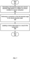
- FIG. 5 a flow diagram depicting an embodiment of a method for operating a sensor is illustrated.
- the method which may be applied to various sensors, begins in block 501.
- the method includes generating, by a sensor, a fine sensor signal based on a rotation of the sensor (block 502).
- the sensor includes an inductive angular position sensor that includes an excitation coil, a rotor coil, a first set of receiver coils, and a second set of receiver coils.
- generating the coarse and fine sensor signals includes applying an alternating current (AC) to the excitation coil.
- AC alternating current
- the method includes generating, by the sensor, a coarse sensor signal based on the rotation of the sensor (block 503).
- a resolution of the coarse sensor signal is less than a resolution of the fine sensor signal.
- generating the coarse sensor signal includes generating a voltage in a second set of receiver coils included in the inductor angular position sensor.
- the method further includes generating, by an interface circuit, a first absolute angle value using the coarse and fine sensor signals (block 504).
- a first most significant portion of the first absolute angle value is based on the fine sensor signal.
- generating the first absolute angle includes performing analog-to-digital conversions of the coarse and fine sensor signals.
- the method also includes generating, by the interface circuit, a second absolute angle value using the fine and coarse sensor signal (block 505).
- a second most significant portion of the second absolute angle value is based on the coarse sensor signal.
- generating the second absolute angle value includes performing analog-to-digital conversions of the fine and coarse sensor signals.
- the method further includes generating, by the interface circuit, an output angle value using a difference between the first absolute angle value and the second absolute angle value (block 506).
- generating the output angle value includes retrieving, by the interface circuit using the first absolute angle value, a particular average error value from a lookup table configured to store a plurality of average error values for a corresponding plurality of fine angle ranges.
- the method may further include combining, by the interface circuit, the particular average error value with a predetermined geometry value to generate a product value, and combining, by the interface circuit, the product value and the first absolute angle value to generate the output angle value.
- the method may include combining, by the interface circuit, the product value and the second absolute angle value to generate the output angle value.
- the method may further include averaging, by the interface circuit over a range of measurements, a difference between the first absolute angle value and the second absolute angle value.
- the method may additionally include updating, by the interface circuit, the lookup table using a result from the averaging.
- the method may include generating an error signal in response to determining that a given average error value for a given range of angles stored in the lookup table exceeds a threshold value. The method concludes in block 507.
- the difference between the fine angle value and the coarse angle value can be averaged over a large number of measurements. Such averaging can be performed during a calibration operation during which sensor 101 is moved through a range of angles.
- a flow diagram depicting an embodiment of a method for performing such a calibration operation is depicted in FIG. 6 .
- the method which may be applied to various sensor subsystems, e.g., sensor subsystem 100, begins in block 601.
- the method includes rotating the sensor through a plurality of positions (block 602).
- rotating the sensor through the plurality of positions includes rotating, for a predetermined number of times, rotor coils 202 and 205 in sensor 101 by a predetermined number of rotations.
- the number of rotations may be based on a resolution of sensor 101.
- the method further includes generating a plurality of first absolute angles and a plurality of second absolute angles corresponding to the plurality of positions (block 603).
- generating the plurality of first absolute angles and the plurality of second absolute angles includes performing an analog-to-digital conversion on fine sensor signals 103 and coarse sensor signals 104 at each of the plurality of positions.
- the method also includes determining a plurality of difference values using the plurality of first absolute angles and corresponding ones of the plurality of second absolute angles (block 604).
- determining the plurality of difference values includes subtracting a given second absolute angle from a corresponding first absolute angle.
- the method further includes updating a plurality of running averages corresponding to the plurality of positions (block 605).
- updating the plurality of running averages includes retrieving a particular running average value from a lookup table, updating the particular running average value, and storing the updated particular running average value back into the lookup table. The method concludes in block 606.
- a calibration operation may be run in parallel with measurement operation.
- a flow diagram depicting an embodiment of a method for performing measurement and calibration operations in parallel is illustrated in FIG. 7 .
- the method which may be applied to various sensor subsystem, e.g., sensor subsystem 100 as depicted in FIG. 1 , begins in block 701.
- the method includes generating a first absolute angle and a second absolute angle based on a rotation of a sensor included in the sensor subsystem (block 702). In various embodiments, the method further includes generating an output angle value based on a difference between the first absolute angle and the second absolute angle. In some cases, generating the output angle value includes retrieving an average error value from a lookup table.
- the method also includes performing a comparison of the first absolute angle and the second absolute angle (block 703).
- performing the comparison of the first absolute angle and the second absolute angle includes determining a difference between the first absolute angle and the second absolute angle, and comparing the difference to a threshold value.
- the method further includes updating the lookup table based on a result of the comparison (block 704).
- updating the lookup table includes retrieving a particular value from the lookup table and averaging the particular value with a new value based on the first absolute angle and the second absolute angle. In such cases, the method also includes updating the lookup table with the average of the particular value and the new value. The method concludes in block 705.
- system 800 includes control circuit 801 and mechanical device 802, which includes sensor subsystem 100.
- system 800 may be used as part of a servo motor control mechanism, a robotic limb control mechanism, a cobot control mechanism, or any other suitable control mechanism.
- Control circuit 801 is configured to receive input signal 803.
- input signal 803 may be either a digital or analog circuit whose value indicates an amount to rotate all or a portion of mechanical device 802.
- control circuit 801 may be configured to generate control signal 804 using input signal 803.
- mechanical device 802 may be configured to rotate at least a portion of itself, e.g., a robotic limb.
- mechanical device 802 may be configured to activate a motor in response to an activation of control signal 804. The motor may then cause a portion of mechanical device 802 to rotate while control signal 804 is active.
- rotation angle 805 may correspond to output angle 107 and may include a word of digital data including any suitable number of bits to achieve a desired resolution of rotation angle 805.
- Control circuit 801 may be further configured to deactivate control signal 804 based on rotation angle 805.
- control circuit 801 may be configured to compare rotation angle 805 to a desired rotation angle. In response to a determination that rotation angle 805 is within a threshold value of the desired rotation angle, control circuit 801 may deactivate control signal 804.
- Control circuit 801 may be implemented using controller.
- An apparatus comprising:
- Clause 2 The apparatus of any clause herein, wherein the sensor includes an inductive angular position sensor.
- Clause 3 The apparatus of clause herein, wherein to generate the first absolute angle value, the interface circuit is configured to perform a first analog-to-digital conversion operation using the fine sensor signal, and wherein to generate the second absolute angle value, the interface circuit is configured to perform a second analog-to-digital conversion operation using the coarse sensor signal.
- Clause 4 The apparatus of any clause herein, wherein the interface circuit includes a lookup table configured to store a plurality of average error values for a corresponding plurality of angle ranges, and wherein to generate the output angle value, the interface circuit is further configured to retrieve a particular average error value from the lookup table using one of the first absolute angle value or the second absolute angle value.
- the interface circuit includes a lookup table configured to store a plurality of average error values for a corresponding plurality of angle ranges, and wherein to generate the output angle value, the interface circuit is further configured to retrieve a particular average error value from the lookup table using one of the first absolute angle value or the second absolute angle value.
- Clause 6 The apparatus of any clause herein, wherein the interface circuit is further configured to update a given average error value stored in the lookup table using a difference of the first absolute angle value and the second absolute angle value.
- Clause 8 The method according to any clause herein, wherein generating the first absolute angle value includes converting, by the interface circuit, the fine sensor signal to a first digital value, and wherein generating the second absolute angle value includes converting, by the interface circuit, the coarse sensor signal to a second digital value.
- Clause 9 The method according to any clause herein, wherein generating the output angle value includes retrieving, by the interface circuit using the first absolute angle value, a particular average error value from a lookup table configured to store a plurality of average error values for a corresponding plurality of fine angle ranges.
- Clause 12 The method according to any clause herein, further comprising generating an error signal in response to determining a given average error for a given range of angle values stored in the lookup table exceeds a threshold value.
- Clause 13 The method according to any clause herein, wherein the sensor includes an inductive angular position sensor.
- Clause 16 The system according to any clause herein, wherein to generate the first absolute angle value, the sensor subsystem is further configured to convert the fine sensor signal to a first digital value, and wherein to generate the second absolute angle value, the sensor subsystem is further configured to convert the coarse sensor signal to a second digital value.
- Clause 17 The system according to any clause herein, wherein the sensor subsystem includes a lookup table configured to store a plurality of average error values for a corresponding plurality of angle ranges, and wherein to generate the rotation angle, the sensor subsystem is further configured to retrieve, using the first absolute angle value, a particular average error value.
- Clause 20 The system according to any clause herein, wherein the sensor subsystem includes an inductive angular position sensor coupled to the component.
Landscapes
- Physics & Mathematics (AREA)
- General Physics & Mathematics (AREA)
- Measurement Of Length, Angles, Or The Like Using Electric Or Magnetic Means (AREA)
- Transmission And Conversion Of Sensor Element Output (AREA)
Abstract
Description
- This disclosure is related to sensors and, more particularly, to inductive angular position sensors.
- In many computer and mechanical systems, a variety of sensors may be employed to detect different environmental and operational conditions, and generate analog or digital signals corresponding to the detected conditions. In some systems, temperature sensors may be employed to detect the temperature of a system in order to determine if the system is operating in a specified temperature range. Other systems may employ accelerometer sensors to aid in the determination of movement of the system or part of the system. In robotic systems, rotational sensors may be used to determine how far a portion of a system, e.g., a robotic arm, has rotated.
- Various embodiments of a sensor subsystem are disclosed. Broadly speaking, a sensor subsystem includes a sensor coupled to an interface circuit. The sensor may be configured to generate a fine sensor signal and a coarse sensor signal based on a rotation of the sensor. The interface circuit may be configured to generate a first absolute angle value and a second absolute angle value using the fine sensor signal and the coarse sensor signal, respectively. The interface circuit may be further configured to generate an output angle value using a difference between the first absolute angle value and the second absolute angle value.
- For a detailed description of example embodiments, reference will now be made to the accompanying drawings in which:
-
FIG. 1 is a block diagram of an embodiment of a sensor subsystem. -
FIG. 2 is a block diagram of an embodiment of a sensor. -
FIG. 3 is a block diagram of an embodiment of an interface circuit for a sensor subsystem. -
FIG. 4 is a block diagram of an embodiment of a lookup table. -
FIG. 5 is a flow diagram of an embodiment of a method for operating a sensor. -
FIG. 6 is flow diagram of an embodiment of a method for calibrating a sensor. -
FIG. 7 is a flow diagram of an embodiment of a method for performing continuous calibration for a sensor. -
FIG. 8 is a block diagram of an embodiment of a system to control rotation of a portion of a mechanical device. - Many of the electrical connections in the drawings are shown as direct couplings having no intervening devices, but are not expressly stated as such in the following description. Nevertheless, this paragraph shall serve as antecedent basis in the claims for referencing any electrical connection as "directly coupled" for electrical connections shown in the drawing with no intervening device(s).
- Various terms are used to refer to particular system components. Different companies may refer to a component by different names - this document does not intend to distinguish between components that differ in name but not function. In the following discussion and in the claims, the terms "including" and "comprising" are used in an open-ended fashion and thus should be interpreted to mean "including, but not limited to...." Also, the term "couple" or "couples" is intended to mean either an indirect or direct connection. Thus, if a first device couples to a second device, that connection may be through a direct connection or through an indirect connection via other devices and connections.
- "A," "an," and "the," as used herein, refers to both singular and plural referents unless the context clearly dictates otherwise. By way of example, "a processor" programmed to perform various functions refers to one processor programmed to perform each and every function, or more than one processor collectively programmed to perform each of the various functions.
- In relation to electrical devices (whether stand alone or as part of an integrated circuit), the terms "input" and "output" refer to electrical connections to the electrical devices, and shall not be read as verbs requiring action. For example, a differential amplifier (such as an operational amplifier) may have a first differential input and a second differential input, and these "inputs" define electrical connections to the operational amplifier, and shall not be read to require inputting signals to the operational amplifier.
- "Controller" or "controller circuit" shall mean, alone or in combination, individual circuit components, an application specific integrated circuit (ASIC), a microcontroller with controlling software, a reduced-instruction-set computing (RISC) circuit with controlling software, a digital signal processor (DSP), a processor with controlling software, a programmable logic device (PLD), a field programmable gate array (FPGA), or a programmable system-on-a-chip (PSOC), configured to read inputs and drive outputs responsive to the inputs.
- Various sensor circuits may be used in a variety of computer, mechanical, and electromechanical systems. Such sensor circuits determine and relay environmental and/or operational information that can be used as part of a control mechanism. For example, to control servo motors, robotic arms, and collaborative robots (referred to as "cobots"), multiple rotation sensors may be employed.
- One type of rotation sensor that can be employed in systems is an inductive angular position sensor. In such sensors, an excitation coil may be fabricated on a printed circuit board ("PCB"), while a rotor that is made from conductive material is connected to an object whose rotation is to be measured, and rotates above the PCB and excitation coil.
- When a current is driven through the excitation coil, a resultant magnetic field induces a current into the rotor. As the induced current flows in the rotor, another magnetic field is generated around the rotor which, in turn, induces respective currents or voltages in one or more receiver coils (referred to as "stators") that are also fabricated on the PCB.
- The coupling of the magnetic field of the rotor into the one or more stators is a function of the angular position of the rotor to the stators. By measuring the voltage polarity and the voltage amplitude induced in the stators, the angle of the rotor relative to the stators can be determined.
- In cases where two stators are employed, each with a different rotational symmetry over the measurement range, the signals from the two stators resolve to a unique angular position of the rotor, provided that the rotational symmetries do not have any common factors other than 1 (referred to as being "co-prime" or "relatively prime"). While such an arrangement of a rotor and stators is relatively immune to rotor eccentricity (i.e., the center of rotation is not above the center of the stator), and rotor tilt (i.e., the axis of rotation is not perpendicular to the plane of the stator), error can result from a lateral movement and tilt of the rotor. In such cases, the coupling between the rotor and the stators will not be completely compensated, which is referred to as "run-out error" and can lead to incorrect determination of the angular position of the rotor.
- Such run-out error is proportional to the product of the eccentricity and tilt values, and is dependent on the geometry of the sensor. For example, a sensor with a high count per revolution is more sensitive than a sensor with a lower count per revolution. The ratio between the high-count error and low-count error is, however, constant.
- The embodiments described herein may provide techniques for compensating for run-out error in an inductive angular position sensor. Using a difference between a low-count sensor signal and a high-count sensor signal, the error introduced by a combination of lateral movement and tilt can be remediated. The addition of a calibration mode enables compensating for variations in tilt and eccentricity that vary over time.
-
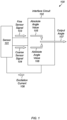
FIG. 1 is a block diagram depicting an embodiment of a sensor subsystem. As illustrated,sensor subsystem 100 includessensor 101 andinterface circuit 102. In various embodiments,sensor 101 may include an inductive angular position sensor. -
Sensor 101 is configured to generatefine sensor signals 103 andcoarse sensor signals 104 based on a rotation ofsensor 101. As described below,sensor 101 may include multiple receiver coils that generate corresponding sensor signals. In some cases, a first set of receiver coils may be used to generatefine sensor signals 103, and a second set of receiver coils may be used to generatecoarse sensor signals 104. For example, in some embodiments, two receiver coils may be used to generate the two signals included infine sensor signals 103, and two other receiver coils may be used to generate the two signals included incoarse sensor signals 104. In some embodiments, the different receiver coils have different geometries that produce a different number of pulses (or "counts") for a complete rotation. In the present embodiment,fine sensor signals 103 has a larger number of pulses for one rotation ofsensor 101 than doescoarse sensor signals 104. Althoughsensor 101 is depicted as generating two sensor signals, in other embodiments,sensor 101 may generate any suitable number of sensor signals. -
Interface circuit 102 is configured to generateabsolute angle value 105 using fine sensor signals 103 and coarse sensor signals 104. Additionally,interface circuit 102 is configured to generateabsolute angle value 106 using coarse sensor signals 104 and fine sensor signals 103. In various embodiments, a most significant portion ofabsolute angle value 105 is based on fine sensor signals 103, while a least significant portion ofabsolute angle value 105 is based on coarse sensor signals 104. For example, the hundreds and tens portion ofabsolute angle value 105 may be based on fine sensor signals 103, while the ones and fractional parts ofabsolute angle value 105 may be based on coarse sensor signals 104. In a similar fashion, a most significant portion ofabsolute angle value 106 is based on coarse sensor signals 104, while a least significant portion ofabsolute angle value 106 is based on fine sensor signals 103. - As described below, to generate
absolute angle value 105 andabsolute angle value 106,interface circuit 102 may be configured to perform an analog-to-digital conversion operation on coarse sensor signals 104 and fine sensor signals 103. - In various embodiments,
interface circuit 102 is configured to generateoutput angle 107 using a difference betweenabsolute angle value 105 andabsolute angle value 106. As described below, to generateoutput angle 107,interface circuit 102 may be further configured to retrieve, from a lookup table, an average error value usingabsolute angle value 106.Interface circuit 102 may be further configured to generateoutput angle 107 using the average error value. - In some embodiments,
interface circuit 102 is configured to generate excitation current 108, whichsensor 101 is configured to use to generate fine sensor signals 103 and coarse sensor signals 104. Excitation current 108 may, in various embodiments, be an alternating current. - Turning to
FIG. 2 , a block diagram of an embodiment ofsensor 101 is depicted. As illustrated,sensor 101 includes excitation coil 201, rotor coil 202,receiver coil 203,receiver coil 204,rotor coil 205,receiver coil 206, andreceiver coil 207. In various embodiments, rotor coil 202,receiver coil 203, andreceiver coil 204 form a fine sensor that is configured to generate fine sensor signals 103, whilerotor coil 205,receiver coil 206, andreceiver coil 207 form a coarse sensor that is configured to generate coarse sensor signals 104. - Excitation coil 201 is fabricated (or "printed") on a PCB (not shown). In various embodiments, excitation coil 201 is fabricated using copper or any other suitable material that can be printed on a PCB. Although excitation coil 201 is depicted as a single trace, in other embodiments, excitation coil 201 may include multiple concentric traces.
- Rotor coils 202 and 205 are fabricated from a conductive material and are configured to rotate above the PCB. In various embodiments, rotor coils 202 and 205 rotate in response to a change in rotational position of a specific object, e.g., a robotic arm. Additionally, rotor coils 202 and 205 may rotate in response to
interface circuit 102 activating a calibration mode. In such cases, rotor coils 202 and 205 rotate through 360 degrees with measurements taken byinterface circuit 102 at various angles. During the calibration mode, rotor coils 202 and 205 may rotate independently of an object, e.g., a robotic arm, to whichrotor coil 204 is attached. - Receiver coils 203 and 204 are also fabricated from a conductive material on the PCB. In a similar fashion, receiver coils 206 and 207 are also fabricated from a conductive material on the PCB. In various embodiments, receiver coils 203 and 204 have different geometries than
receiver coils receiver coils FIG. 2 , in other embodiments, any suitable number of receiver coils may be employed for the fine and coarse sensors. - To measure the rotation of rotor coil 202,
interface circuit 102 is configured to apply an alternating current signal to excitation coil 201. As the alternating current flows in excitation coil 201, a magnetic field is generated around excitation coil 201. In various embodiments, the coupling from excitation coil 201 torotor coils 202 and 205 is independent of the angular position of rotor coils 202 and 205, but is a function of a distance between excitation coil 201 androtor coils 202 and 205. - The magnetic field generated by excitation coil 201 induces a current in rotor coils 202 and 205, which, in turn, generates a magnetic field around
rotor coils 202 and 205. The magnetic field generated by the induced current in rotor coils 202 and 205 couples intoreceiver coils receiver coils receiver coils rotor coil 205 has different rotational symmetry thanreceiver coils rotor coil 205 andreceiver coils - The magnetic field generated by
rotor coil 204 induces respective currents or voltages in bothreceiver coils 202 and 203. As described below,interface circuit 102 is configured to measure the polarity and amplitude of the respective voltages ofreceiver coils 202 and 203. Using the polarity and amplitude measurements,interface circuit 102 is further configured to determineoutput angle 107. As described above, a number of peaks in the signals ofreceiver coils 202 and 203 can depend on the geometry ofreceiver coils 202 and 203. In various embodiments, receiver coil 202 may generate coarse sensor signals 104, whilereceiver coil 203 may generate fine sensor signals 103. - Turning to
FIG. 3 , a block diagram ofinterface circuit 102 is depicted. As illustrated,interface circuit 102 includescoarse interface circuit 301,fine interface circuit 302,calculation circuit 303,calculation circuit 304,subtractor circuit 305,adder circuit 306,multiplier circuit 307, lookup table 308,interpolation circuit 309, andcoil driver circuit 310. -
Coarse interface circuit 301 is configured to generate signal 316 using coarse sensor signals 104. In various embodiments, signal 316 may be a digital signal that includes multiple bits of data. In such cases,coarse interface circuit 301 may include an analog-to-digital converter circuit configured to translate an amplitude of coarse sensor signals 104 into the multiple bits of data. -
Fine interface circuit 302 is configured to generate signal 317 using fine sensor signals 103. Likesignal 316, signal 317 may also be a digital signal that includes multiple bits of data. In various embodiments,fine interface circuit 302 may include an analog-to-digital converter circuit configured to generate the multiple bits of data based on an amplitude of fine sensor signals 103. -
Calculation circuit 303 is configured to generateabsolute angle value 106 usingsignal 316 and signal 317. In various embodiments,calculation circuit 303 may be configured to calculateabsolute angle value 106 such that a most significant portion ofabsolute angle value 106 is based onsignal 316, while a least significant portion ofabsolute angle value 106 is based onsignal 317. In some embodiments,calculation circuit 303 may be implemented using a controller, or any other suitable combination of combinatorial and sequential logic circuits. -
Calculation circuit 304 is configured to generateabsolute angle value 105 usingsignal 316 and signal 317. In various embodiments,calculation circuit 304 may be configured to calculatedabsolute angle value 105 such that a most significant portion ofabsolute angle value 105 is based onsignal 317, while a least significant portion ofabsolute angle value 105 is based onsignal 316. In some embodiments,calculation circuit 303 may be implemented using a controller, or any other suitable combination of combinatorial and sequential logic circuits. - It is noted that, in some embodiments,
calculation circuits calculation circuit 304 may be used to generateabsolute angle value 106, whilecalculation circuit 303 may be used to generateabsolute angle value 105. -
Subtractor circuit 305 is configured to generate difference signal 311 usingabsolute angle value 106 andabsolute angle value 105. In various embodiments, to generatedifference signal 311,subtractor circuit 305 may be configured to subtractabsolute angle value 106 fromabsolute angle value 105. -
Adder circuit 306 is configured to generateoutput angle 107 usingabsolute angle value 105 andproduct signal 312. In various embodiments, to generateoutput angle 107,adder circuit 306 may be configured to addabsolute angle value 105 toproduct signal 312. Although the embodiment ofFIG. 3 depictsadder circuit 306 combiningabsolute angle value 105 andproduct signal 312 to generateoutput angle 107, in other embodiments,adder circuit 306 may be configured to combineabsolute angle value 106 andproduct signal 312 to generateoutput angle 107. - In the case of an ideal sensor,
absolute angle value 106 andabsolute angle value 105 would be identical. Noise on coarse sensor signals 104 and fine sensor signals 103 can result in noise inabsolute angle value 106 andabsolute angle value 105, respectively, resulting in a difference between the two angle values. In various embodiments, such noise may include random noise in the system. In some cases, the noise on coarse sensor signals 104 and fine sensor signals 103 may include systematic error due to tilt and eccentricity between the receiver coils and the rotor coils ofsensor 101. To remove the random portion of the noise, difference signal 311 (which is the difference betweenabsolute angle value 106 and absolute angle value 105) can be averaged and stored in lookup table 308. Averagingdifference signal 311 will, however, preserve any systematic error. - Lookup table 308 is configured to store multiple error average values for corresponding ranges of angles. In various embodiments, lookup table 308 is configured to select a particular error average using
absolute angle value 105 to generate error signal 314. In various embodiments, running averages of error values, i.e., the differences betweenabsolute angle value 106 andabsolute angle value 105, are generated and stored in lookup table 308 during calibration modes. Alternatively, the values in lookup table 308 can be continuously updated by detecting whenabsolute angle value 105 is within a particular range of values and then, upon detecting such a situation, updating the corresponding error average. By updating the error averages in such a fashion,sensor subsystem 100 can tolerate variation in tilt and eccentricity ofrotor coil 204 over time due to rotor shaft bearing wear and tear. -
Interpolation circuit 309 is configured to generate interpolatedsignal 313 using multiple error signals, e.g., error signal 314, from lookup table 308. In various embodiments,interpolation circuit 309 may be configured to perform a piece-wise linear interpolation between the error average values stored in lookup table 308 to generate interpolatedsignal 313. - During non-calibration operation (referred to as "run mode"), data stored in lookup table 308 can be used to correct the measured angle value. Prior to combining the interpolated data from lookup table 308, i.e., interpolated
signal 313, withabsolute angle value 105, interpolatedsignal 313 may be scaled based on the geometry of receiver coils 203, 204, 206, and 207. Such scaling is accomplished bymultiplier circuit 307. -
Multiplier circuit 307 is configured to generateproduct signal 312 using interpolatedsignal 313 andgeometry factor 315. In various embodiments,geometry factor 315 is based on the respective geometries of receiver coils receiver coils 203, 204, 206 and 207 insensor 101. In some cases,geometry factor 315 is determined by simulation, or measurement in a laboratory, and then added to software/firmware used byinterface circuit 102. In some cases,geometry factor 315 may be based on respective diameters and counts-per-revolution of receiver coils 203, 204, 206 and 207. -
Adder circuit 306 is configured to generateoutput angle 107 usingabsolute angle value 105 andproduct signal 312. In various embodiments, to generateoutput angle 107,adder circuit 306 may be configured to addabsolute angle value 105 toproduct signal 312. -
Coil driver circuit 310 is configured to generate excitation current 108. As described above, excitation current 108 may be an alternating current. In such cases,coil driver circuit 310 may be implemented using an inductor-capacitor (or "LC") oscillator circuit, or any other suitable circuit configured to generate an alternating current. - Turning to
FIG. 4 , a block diagram of lookup table 308 is depicted. As illustrated, lookup table 308 stores error average values for multiple different angle ranges ofabsolute angle value 105, which corresponds to fine sensor signals 103. For a given angle range, lookup table 308 stores a corresponding error average value. For example, for angles between 22.5 and 45 degrees, lookup table 308 stores erroraverage value 402. Although sixteen entries are depicted in the embodiment depicted inFIG. 4 , in other embodiments, any suitable number of entries may be employed. In various embodiments, a number of entries included in lookup table 308 may be based on a desired resolution of the error average values. - As described above, a given error average value is read from lookup table 308 as part of the process to generate
output angle 107 for a new rotational position ofsensor 101. Error average values 401-416 are updated as running averages during a calibration operation. - It is noted that circuitry for reading and writing information into lookup table 308 has been omitted from the diagram of
FIG. 4 for clarity. In various embodiments, lookup table 308 may be implemented using multiple static random-access memory (SRAM) storage cells, nonvolatile memory circuits (e.g., EEPROM or Flash), decoder circuits, sense amplifier circuits, and the like. - Turning to
FIG. 5 , a flow diagram depicting an embodiment of a method for operating a sensor is illustrated. The method, which may be applied to various sensors, begins inblock 501. - The method includes generating, by a sensor, a fine sensor signal based on a rotation of the sensor (block 502). In various embodiments, the sensor includes an inductive angular position sensor that includes an excitation coil, a rotor coil, a first set of receiver coils, and a second set of receiver coils. In some embodiments, generating the coarse and fine sensor signals includes applying an alternating current (AC) to the excitation coil.
- The method includes generating, by the sensor, a coarse sensor signal based on the rotation of the sensor (block 503). In various embodiments, a resolution of the coarse sensor signal is less than a resolution of the fine sensor signal. In some embodiments, generating the coarse sensor signal includes generating a voltage in a second set of receiver coils included in the inductor angular position sensor.
- The method further includes generating, by an interface circuit, a first absolute angle value using the coarse and fine sensor signals (block 504). In various embodiments, a first most significant portion of the first absolute angle value is based on the fine sensor signal. In some embodiments, generating the first absolute angle includes performing analog-to-digital conversions of the coarse and fine sensor signals.
- The method also includes generating, by the interface circuit, a second absolute angle value using the fine and coarse sensor signal (block 505). In various embodiments, a second most significant portion of the second absolute angle value is based on the coarse sensor signal. In some embodiments, generating the second absolute angle value includes performing analog-to-digital conversions of the fine and coarse sensor signals.
- The method further includes generating, by the interface circuit, an output angle value using a difference between the first absolute angle value and the second absolute angle value (block 506). In various embodiments, generating the output angle value includes retrieving, by the interface circuit using the first absolute angle value, a particular average error value from a lookup table configured to store a plurality of average error values for a corresponding plurality of fine angle ranges. In some embodiments, the method may further include combining, by the interface circuit, the particular average error value with a predetermined geometry value to generate a product value, and combining, by the interface circuit, the product value and the first absolute angle value to generate the output angle value. Alternatively, the method may include combining, by the interface circuit, the product value and the second absolute angle value to generate the output angle value.
- In various embodiments, the method may further include averaging, by the interface circuit over a range of measurements, a difference between the first absolute angle value and the second absolute angle value. The method may additionally include updating, by the interface circuit, the lookup table using a result from the averaging. In some embodiments, the method may include generating an error signal in response to determining that a given average error value for a given range of angles stored in the lookup table exceeds a threshold value. The method concludes in block 507.
- To remove noise from
sensor subsystem 100, the difference between the fine angle value and the coarse angle value can be averaged over a large number of measurements. Such averaging can be performed during a calibration operation during whichsensor 101 is moved through a range of angles. A flow diagram depicting an embodiment of a method for performing such a calibration operation is depicted inFIG. 6 . The method, which may be applied to various sensor subsystems, e.g.,sensor subsystem 100, begins inblock 601. - The method includes rotating the sensor through a plurality of positions (block 602). In various embodiments, rotating the sensor through the plurality of positions includes rotating, for a predetermined number of times, rotor coils 202 and 205 in
sensor 101 by a predetermined number of rotations. In various embodiments, the number of rotations may be based on a resolution ofsensor 101. - The method further includes generating a plurality of first absolute angles and a plurality of second absolute angles corresponding to the plurality of positions (block 603). In various embodiments, generating the plurality of first absolute angles and the plurality of second absolute angles includes performing an analog-to-digital conversion on fine sensor signals 103 and coarse sensor signals 104 at each of the plurality of positions.
- The method also includes determining a plurality of difference values using the plurality of first absolute angles and corresponding ones of the plurality of second absolute angles (block 604). In various embodiments, determining the plurality of difference values includes subtracting a given second absolute angle from a corresponding first absolute angle.
- The method further includes updating a plurality of running averages corresponding to the plurality of positions (block 605). In some embodiments, updating the plurality of running averages includes retrieving a particular running average value from a lookup table, updating the particular running average value, and storing the updated particular running average value back into the lookup table. The method concludes in
block 606. - In various embodiments, a calibration operation may be run in parallel with measurement operation. A flow diagram depicting an embodiment of a method for performing measurement and calibration operations in parallel is illustrated in
FIG. 7 . The method, which may be applied to various sensor subsystem, e.g.,sensor subsystem 100 as depicted inFIG. 1 , begins in block 701. - The method includes generating a first absolute angle and a second absolute angle based on a rotation of a sensor included in the sensor subsystem (block 702). In various embodiments, the method further includes generating an output angle value based on a difference between the first absolute angle and the second absolute angle. In some cases, generating the output angle value includes retrieving an average error value from a lookup table.
- The method also includes performing a comparison of the first absolute angle and the second absolute angle (block 703). In various embodiments, performing the comparison of the first absolute angle and the second absolute angle includes determining a difference between the first absolute angle and the second absolute angle, and comparing the difference to a threshold value.
- The method further includes updating the lookup table based on a result of the comparison (block 704). In some embodiments, updating the lookup table includes retrieving a particular value from the lookup table and averaging the particular value with a new value based on the first absolute angle and the second absolute angle. In such cases, the method also includes updating the lookup table with the average of the particular value and the new value. The method concludes in
block 705. - Turning to
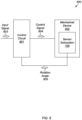
FIG. 8 , a block diagram of a system configured to control rotation of a portion of a mechanical device is depicted. As illustrated,system 800 includescontrol circuit 801 andmechanical device 802, which includessensor subsystem 100. In various embodiments,system 800 may be used as part of a servo motor control mechanism, a robotic limb control mechanism, a cobot control mechanism, or any other suitable control mechanism. -
Control circuit 801 is configured to receiveinput signal 803. In various embodiments,input signal 803 may be either a digital or analog circuit whose value indicates an amount to rotate all or a portion ofmechanical device 802. In various embodiments,control circuit 801 may be configured to generate control signal 804 usinginput signal 803. - In response to receiving
control signal 804,mechanical device 802 may be configured to rotate at least a portion of itself, e.g., a robotic limb. For example,mechanical device 802 may be configured to activate a motor in response to an activation ofcontrol signal 804. The motor may then cause a portion ofmechanical device 802 to rotate while control signal 804 is active. - As described above,
sensor subsystem 100 is configured to generate rotation angle 805 based on the rotation of the portion ofmechanical device 802. In various embodiments, rotation angle 805 may correspond tooutput angle 107 and may include a word of digital data including any suitable number of bits to achieve a desired resolution of rotation angle 805. -
Control circuit 801 may be further configured to deactivate control signal 804 based on rotation angle 805. In various embodiments,control circuit 801 may be configured to compare rotation angle 805 to a desired rotation angle. In response to a determination that rotation angle 805 is within a threshold value of the desired rotation angle,control circuit 801 may deactivatecontrol signal 804.Control circuit 801 may be implemented using controller. - Clause 1: An apparatus, comprising:
- a sensor configured to generate a fine sensor signal and a coarse sensor signal based on a rotation of the sensor; and
- an interface circuit configured to:
- generate a first absolute angle value using the fine sensor signal and the coarse sensor signal, wherein a first most significant portion of the first absolute angle value is based on the fine sensor signal;
- generate a second absolute angle value using the coarse sensor signal and the fine sensor signal, wherein a second most signification portion of the second absolute angle value is based on the coarse sensor signal; and
- generate an output angle value using a difference between the first absolute angle value and the second absolute angle value.
- Clause 2: The apparatus of any clause herein, wherein the sensor includes an inductive angular position sensor.
- Clause 3: The apparatus of clause herein, wherein to generate the first absolute angle value, the interface circuit is configured to perform a first analog-to-digital conversion operation using the fine sensor signal, and wherein to generate the second absolute angle value, the interface circuit is configured to perform a second analog-to-digital conversion operation using the coarse sensor signal.
- Clause 4: The apparatus of any clause herein, wherein the interface circuit includes a lookup table configured to store a plurality of average error values for a corresponding plurality of angle ranges, and wherein to generate the output angle value, the interface circuit is further configured to retrieve a particular average error value from the lookup table using one of the first absolute angle value or the second absolute angle value.
- Clause 5: The apparatus of any clause herein, wherein the interface circuit is further configured to:
- combine the particular average error value with a predetermined geometry value to generate a product value; and
- combine the product value and the first absolute angle value or the second absolute angle value to generate the output angle value.
- Clause 6: The apparatus of any clause herein, wherein the interface circuit is further configured to update a given average error value stored in the lookup table using a difference of the first absolute angle value and the second absolute angle value.
- Clause 7: A method, comprising:
- generating, by a sensor, a fine sensor signal based on a rotation of the sensor;
- generating, by the sensor, a coarse sensor signal based on the rotation of the sensor, wherein a resolution of the coarse sensor signal is less than a resolution of the fine sensor signal;
- generating, by an interface circuit, a first absolute angle value using the fine sensor signal and the coarse sensor signal, wherein a first most significant portion of the first absolute angle value is based on the fine sensor signal;
- generating, by the interface circuit, a second absolute angle value using the coarse sensor signal and the fine sensor signal, wherein a second most significant portion of the second absolute angle value is based on the coarse sensor signal; and
- generating, by the interface circuit, an output angle value using a difference between the first absolute angle value and the second absolute angle value.
- Clause 8: The method according to any clause herein, wherein generating the first absolute angle value includes converting, by the interface circuit, the fine sensor signal to a first digital value, and wherein generating the second absolute angle value includes converting, by the interface circuit, the coarse sensor signal to a second digital value.
- Clause 9: The method according to any clause herein, wherein generating the output angle value includes retrieving, by the interface circuit using the first absolute angle value, a particular average error value from a lookup table configured to store a plurality of average error values for a corresponding plurality of fine angle ranges.
- Clause 10: The method according to any clause herein, wherein generating the output angle value includes:
- combining, by the interface circuit, the particular average error value with a predetermined geometry value to generate a product value; and
- combining, by the interface circuit, the product value and the first absolute angle value or the second absolute angle value to generate the output angle value.
- Clause 11: The method according to any clause herein, further comprising:
- averaging, by the interface circuit over a range of measurements, a difference between the first absolute angle value and the second absolute angle value; and
- updating, by the interface circuit, the lookup table using a result from the averaging.
- Clause 12: The method according to any clause herein, further comprising generating an error signal in response to determining a given average error for a given range of angle values stored in the lookup table exceeds a threshold value.
- Clause 13: The method according to any clause herein, wherein the sensor includes an inductive angular position sensor.
- Clause 14: A system, comprising:
- a mechanical device that includes a component configured to rotate based on a control signal;
- a sensor subsystem configured to generate a rotation angle based on a rotation of the component; and
- a control circuit configured to generate the control signal using an input signal and the rotation angle.
- Clause 15: The system according to any clause herein, wherein to generate the rotation angle, the sensor subsystem is further configured to:
- generate a fine sensor signal based on a position of the component;
- generate a coarse sensor signal based on the position of the component;
- generate a first absolute angle value using the fine sensor signal and the coarse sensor signal, wherein a first most significant portion of the first absolute angle value is based on the coarse sensor signal;
- generate a second absolute angle value using the coarse sensor signal and the fine sensor signal, wherein a second most significant portion of the second absolute angle value is based on the fine sensor signal; and
- generate the rotation angle using a difference between the first absolute angle value and the second absolute angle value.
- Clause 16: The system according to any clause herein, wherein to generate the first absolute angle value, the sensor subsystem is further configured to convert the fine sensor signal to a first digital value, and wherein to generate the second absolute angle value, the sensor subsystem is further configured to convert the coarse sensor signal to a second digital value.
- Clause 17: The system according to any clause herein, wherein the sensor subsystem includes a lookup table configured to store a plurality of average error values for a corresponding plurality of angle ranges, and wherein to generate the rotation angle, the sensor subsystem is further configured to retrieve, using the first absolute angle value, a particular average error value.
- Clause 18: The system according to any clause herein, wherein the sensor subsystem is further configured to:
- combine the particular average error value with a predetermined geometry value to generate a product value; and
- combine the product value and the first absolute angle value to generate the rotation angle.
- Clause 19: The system according to any clause herein, wherein the sensor subsystem is further configured to:
- generate, over a range of measurements, an average value of a difference between the first absolute angle value and the second absolute angle value; and
- update, using the average value, the lookup table.
- Clause 20: The system according to any clause herein, wherein the sensor subsystem includes an inductive angular position sensor coupled to the component.
- The present disclosure includes references to "an embodiment" or groups of "embodiments." As used herein, embodiments are different implementations of instances of the disclosed concepts. References to "an embodiment," "some embodiments," and the like do not necessarily refer to the same embodiment. Many embodiments are possible and contemplated, including those specifically disclosed as well as modifications or alternatives that fall within the spirit or scope of the disclosure.
- The above disclosure is meant to illustrate some of the principles and various embodiments of the disclosed concepts. Numerous variations and modifications will become apparent to those skilled in the art once the above disclosure is fully appreciated. It is intended that the following claims be interpreted to embrace all such variations and modifications.
Claims (10)
- An apparatus, comprising:a sensor configured to generate a fine sensor signal and a coarse sensor signal based on a rotation of the sensor; andan interface circuit configured to:generate a first absolute angle value using the fine sensor signal and the coarse sensor signal, wherein a first most significant portion of the first absolute angle value is based on the fine sensor signal;generate a second absolute angle value using the coarse sensor signal and the fine sensor signal, wherein a second most signification portion of the second absolute angle value is based on the coarse sensor signal; andgenerate an output angle value using a difference between the first absolute angle value and the second absolute angle value.
- The apparatus of claim 1, wherein the sensor includes an inductive angular position sensor.
- The apparatus of any preceding claim, wherein to generate the first absolute angle value, the interface circuit is configured to perform a first analog-to-digital conversion operation using the fine sensor signal, and wherein to generate the second absolute angle value, the interface circuit is configured to perform a second analog-to-digital conversion operation using the coarse sensor signal.
- The apparatus of any preceding claim, wherein the interface circuit includes a lookup table configured to store a plurality of average error values for a corresponding plurality of angle ranges, and wherein to generate the output angle value, the interface circuit is further configured to retrieve a particular average error value from the lookup table using one of the first absolute angle value or the second absolute angle value.
- The apparatus of claim 4, wherein the interface circuit is further configured to:combine the particular average error value with a predetermined geometry value to generate a product value;combine the product value and the first absolute angle value or the second absolute angle value to generate the output angle value; andupdate a given average error value stored in the lookup table using a difference of the first absolute angle value and the second absolute angle value.
- A method, comprising:generating, by a sensor, a fine sensor signal based on a rotation of the sensor;generating, by the sensor, a coarse sensor signal based on the rotation of the sensor, wherein a resolution of the coarse sensor signal is less than a resolution of the fine sensor signal;generating, by an interface circuit, a first absolute angle value using the fine sensor signal and the coarse sensor signal, wherein a first most significant portion of the first absolute angle value is based on the fine sensor signal;generating, by the interface circuit, a second absolute angle value using the coarse sensor signal and the fine sensor signal, wherein a second most significant portion of the second absolute angle value is based on the coarse sensor signal; andgenerating, by the interface circuit, an output angle value using a difference between the first absolute angle value and the second absolute angle value.
- The method of claim 6, wherein generating the first absolute angle value includes converting, by the interface circuit, the fine sensor signal to a first digital value, and wherein generating the second absolute angle value includes converting, by the interface circuit, the coarse sensor signal to a second digital value.
- The method of any of claims 6-7, wherein generating the output angle value includes retrieving, by the interface circuit using the first absolute angle value, a particular average error value from a lookup table configured to store a plurality of average error values for a corresponding plurality of fine angle ranges.
- The method of claim 8, wherein the sensor includes an inductive angular position sensor, and wherein generating the output angle value includes:combining, by the interface circuit, the particular average error value with a predetermined geometry value to generate a product value; andcombining, by the interface circuit, the product value and the first absolute angle value or the second absolute angle value to generate the output angle value.
- The method of claim 8, further comprising:averaging, by the interface circuit over a range of measurements, a difference between the first absolute angle value and the second absolute angle value;updating, by the interface circuit, the lookup table using a result from the averaging; andgenerating an error signal in response to determining a given average error for a given range of angle values stored in the lookup table exceeds a threshold value.
Applications Claiming Priority (1)
| Application Number | Priority Date | Filing Date | Title |
|---|---|---|---|
| US18/541,195 US20250198740A1 (en) | 2023-12-15 | 2023-12-15 | Self-correcting inductive sensor |
Publications (1)
| Publication Number | Publication Date |
|---|---|
| EP4571266A1 true EP4571266A1 (en) | 2025-06-18 |
Family
ID=91129030
Family Applications (1)
| Application Number | Title | Priority Date | Filing Date |
|---|---|---|---|
| EP24175793.9A Pending EP4571266A1 (en) | 2023-12-15 | 2024-05-14 | Self-correcting inductive sensor |
Country Status (4)
| Country | Link |
|---|---|
| US (1) | US20250198740A1 (en) |
| EP (1) | EP4571266A1 (en) |
| JP (1) | JP2025102686A (en) |
| CN (1) | CN120160659A (en) |
Citations (5)
| Publication number | Priority date | Publication date | Assignee | Title |
|---|---|---|---|---|
| EP1876423A2 (en) * | 2006-07-04 | 2008-01-09 | Toyo Denso Kabushiki Kaisha | Rudder angle sensor |
| DE102011103576A1 (en) * | 2011-05-30 | 2012-12-06 | Megamotive Gmbh & Co. Kg | Rotational angle sensor, has sensor device comprising magnet and potentiometer wiper that are displaced along shaft during rotation of sensor device in linear manner, and sensor element attached to magnet and wiper |
| US20140117980A1 (en) * | 2012-06-13 | 2014-05-01 | Cambridge Integrated Circuits Limited | Position sensing transducer |
| CN111193357A (en) * | 2020-01-14 | 2020-05-22 | 连云港杰瑞电子有限公司 | Induction type absolute angle sensor |
| US20230273051A1 (en) * | 2022-02-25 | 2023-08-31 | Semiconductor Components Industries, Llc | Vernier sensor with self calibration |
Family Cites Families (12)
| Publication number | Priority date | Publication date | Assignee | Title |
|---|---|---|---|---|
| US5489845A (en) * | 1994-09-19 | 1996-02-06 | Ford Motor Company | Encoder system and method for determining absolute rotor position by taking a mid value of the multiple coil output sinusoidal signals |
| DE19849554C1 (en) * | 1998-10-27 | 2000-03-02 | Ruf Electronics Gmbh | Method to determine absolute position with displacement and angle transducers; involves using two mechanically coupled sensors with output signals with numbers of periods different by one |
| US8742715B2 (en) * | 2011-06-09 | 2014-06-03 | Simmonds Precision Products, Inc. | System and method for providing control of an electric motor using inductive rotary sensor |
| FR3039269B1 (en) * | 2015-07-21 | 2017-08-11 | Electricfil Automotive | SENSOR FOR MEASURING THE ABSOLUTE POSITION OF A MOBILE |
| US9914477B2 (en) * | 2015-12-10 | 2018-03-13 | Ksr Ip Holdings Llc | Inductive steering torque and angle sensor |
| JP6477933B2 (en) * | 2017-04-25 | 2019-03-06 | 日本精工株式会社 | Rotation angle detection device and rotation angle detection method |
| DE102019213174B9 (en) * | 2019-08-30 | 2023-04-06 | Infineon Technologies Ag | INDUCTIVE ANGLE SENSOR |
| EP4047323B1 (en) * | 2021-02-17 | 2023-07-26 | Melexis Technologies SA | Inductive angular sensor method and system |
| US12366470B2 (en) * | 2021-06-28 | 2025-07-22 | Asahi Kasei Microdevices Corporation | Calibration apparatus, calibration method, and non-transitory computer readable medium having recorded thereon calibration program |
| DE112022003815T5 (en) * | 2021-08-05 | 2024-05-29 | Microchip Technology Incorporated | INDUCTIVE ANGULAR POSITION SENSORS AND RELATED DEVICES, SYSTEMS AND METHODS |
| EP4198458B1 (en) * | 2021-12-20 | 2024-04-24 | Melexis Technologies SA | Device and method for determining an angular position of inductive position sensor |
| DE102024101601A1 (en) * | 2023-03-24 | 2024-09-26 | Melexis Technologies Sa | INDUCTIVE ANGLE SENSOR AND TORQUE SENSOR |
-
2023
- 2023-12-15 US US18/541,195 patent/US20250198740A1/en active Pending
-
2024
- 2024-05-14 EP EP24175793.9A patent/EP4571266A1/en active Pending
- 2024-06-21 CN CN202410811993.4A patent/CN120160659A/en active Pending
- 2024-12-02 JP JP2024209519A patent/JP2025102686A/en active Pending
Patent Citations (5)
| Publication number | Priority date | Publication date | Assignee | Title |
|---|---|---|---|---|
| EP1876423A2 (en) * | 2006-07-04 | 2008-01-09 | Toyo Denso Kabushiki Kaisha | Rudder angle sensor |
| DE102011103576A1 (en) * | 2011-05-30 | 2012-12-06 | Megamotive Gmbh & Co. Kg | Rotational angle sensor, has sensor device comprising magnet and potentiometer wiper that are displaced along shaft during rotation of sensor device in linear manner, and sensor element attached to magnet and wiper |
| US20140117980A1 (en) * | 2012-06-13 | 2014-05-01 | Cambridge Integrated Circuits Limited | Position sensing transducer |
| CN111193357A (en) * | 2020-01-14 | 2020-05-22 | 连云港杰瑞电子有限公司 | Induction type absolute angle sensor |
| US20230273051A1 (en) * | 2022-02-25 | 2023-08-31 | Semiconductor Components Industries, Llc | Vernier sensor with self calibration |
Also Published As
| Publication number | Publication date |
|---|---|
| US20250198740A1 (en) | 2025-06-19 |
| JP2025102686A (en) | 2025-07-08 |
| CN120160659A (en) | 2025-06-17 |
Similar Documents
| Publication | Publication Date | Title |
|---|---|---|
| CN107148741B (en) | Position estimation method and position control device | |
| US6826499B2 (en) | Method and apparatus for calibrating and initializing an electronically commutated motor | |
| KR102536006B1 (en) | Magnetic sensor position measurement with phase compensation | |
| EP2559971B1 (en) | Rotation angle detection device | |
| EP1979704B1 (en) | Encoder signal analysis system for high-resolution position measurement | |
| US9255817B2 (en) | Rotation-angle detection device, image processing apparatus, and rotation-angle detection method | |
| JP4923730B2 (en) | Compensation method and angle detection apparatus using the same in resolver angle detection | |
| US8271221B2 (en) | Phase detection device and position detection device | |
| KR100478978B1 (en) | Apparatus for resolution of angular position using hall-ic and method thereof | |
| EP4571266A1 (en) | Self-correcting inductive sensor | |
| WO2008056793A1 (en) | Rotation angle determining apparatus | |
| JP4224154B2 (en) | Self-calibration type angle detection device and detection accuracy calibration method | |
| JP5708986B2 (en) | Rotation angle detector | |
| JP2006042537A (en) | Brushless dc motor added with magnetic encoder and signal processing circuit | |
| JP5800086B2 (en) | Position detector | |
| US20250020489A1 (en) | Rotor for inductive position sensor |
Legal Events
| Date | Code | Title | Description |
|---|---|---|---|
| PUAI | Public reference made under article 153(3) epc to a published international application that has entered the european phase |
Free format text: ORIGINAL CODE: 0009012 |
|
| STAA | Information on the status of an ep patent application or granted ep patent |
Free format text: STATUS: THE APPLICATION HAS BEEN PUBLISHED |
|
| AK | Designated contracting states |
Kind code of ref document: A1 Designated state(s): AL AT BE BG CH CY CZ DE DK EE ES FI FR GB GR HR HU IE IS IT LI LT LU LV MC ME MK MT NL NO PL PT RO RS SE SI SK SM TR |
|
| STAA | Information on the status of an ep patent application or granted ep patent |
Free format text: STATUS: REQUEST FOR EXAMINATION WAS MADE |
|
| P01 | Opt-out of the competence of the unified patent court (upc) registered |
Free format text: CASE NUMBER: APP_29384/2025 Effective date: 20250620 |
|
| 17P | Request for examination filed |
Effective date: 20250627 |