EP4571265A2 - Sensor arrangement having a dual magnet - Google Patents
Sensor arrangement having a dual magnet Download PDFInfo
- Publication number
- EP4571265A2 EP4571265A2 EP25174338.1A EP25174338A EP4571265A2 EP 4571265 A2 EP4571265 A2 EP 4571265A2 EP 25174338 A EP25174338 A EP 25174338A EP 4571265 A2 EP4571265 A2 EP 4571265A2
- Authority
- EP
- European Patent Office
- Prior art keywords
- magnetically
- magnet
- magnets
- hall effect
- effect sensor
- Prior art date
- Legal status (The legal status is an assumption and is not a legal conclusion. Google has not performed a legal analysis and makes no representation as to the accuracy of the status listed.)
- Pending
Links
Images




Classifications
-
- G—PHYSICS
- G01—MEASURING; TESTING
- G01D—MEASURING NOT SPECIALLY ADAPTED FOR A SPECIFIC VARIABLE; ARRANGEMENTS FOR MEASURING TWO OR MORE VARIABLES NOT COVERED IN A SINGLE OTHER SUBCLASS; TARIFF METERING APPARATUS; MEASURING OR TESTING NOT OTHERWISE PROVIDED FOR
- G01D5/00—Mechanical means for transferring the output of a sensing member; Means for converting the output of a sensing member to another variable where the form or nature of the sensing member does not constrain the means for converting; Transducers not specially adapted for a specific variable
- G01D5/12—Mechanical means for transferring the output of a sensing member; Means for converting the output of a sensing member to another variable where the form or nature of the sensing member does not constrain the means for converting; Transducers not specially adapted for a specific variable using electric or magnetic means
- G01D5/14—Mechanical means for transferring the output of a sensing member; Means for converting the output of a sensing member to another variable where the form or nature of the sensing member does not constrain the means for converting; Transducers not specially adapted for a specific variable using electric or magnetic means influencing the magnitude of a current or voltage
- G01D5/142—Mechanical means for transferring the output of a sensing member; Means for converting the output of a sensing member to another variable where the form or nature of the sensing member does not constrain the means for converting; Transducers not specially adapted for a specific variable using electric or magnetic means influencing the magnitude of a current or voltage using Hall-effect devices
-
- G—PHYSICS
- G01—MEASURING; TESTING
- G01D—MEASURING NOT SPECIALLY ADAPTED FOR A SPECIFIC VARIABLE; ARRANGEMENTS FOR MEASURING TWO OR MORE VARIABLES NOT COVERED IN A SINGLE OTHER SUBCLASS; TARIFF METERING APPARATUS; MEASURING OR TESTING NOT OTHERWISE PROVIDED FOR
- G01D5/00—Mechanical means for transferring the output of a sensing member; Means for converting the output of a sensing member to another variable where the form or nature of the sensing member does not constrain the means for converting; Transducers not specially adapted for a specific variable
- G01D5/12—Mechanical means for transferring the output of a sensing member; Means for converting the output of a sensing member to another variable where the form or nature of the sensing member does not constrain the means for converting; Transducers not specially adapted for a specific variable using electric or magnetic means
- G01D5/14—Mechanical means for transferring the output of a sensing member; Means for converting the output of a sensing member to another variable where the form or nature of the sensing member does not constrain the means for converting; Transducers not specially adapted for a specific variable using electric or magnetic means influencing the magnitude of a current or voltage
- G01D5/142—Mechanical means for transferring the output of a sensing member; Means for converting the output of a sensing member to another variable where the form or nature of the sensing member does not constrain the means for converting; Transducers not specially adapted for a specific variable using electric or magnetic means influencing the magnitude of a current or voltage using Hall-effect devices
- G01D5/145—Mechanical means for transferring the output of a sensing member; Means for converting the output of a sensing member to another variable where the form or nature of the sensing member does not constrain the means for converting; Transducers not specially adapted for a specific variable using electric or magnetic means influencing the magnitude of a current or voltage using Hall-effect devices influenced by the relative movement between the Hall device and magnetic fields
-
- G—PHYSICS
- G01—MEASURING; TESTING
- G01D—MEASURING NOT SPECIALLY ADAPTED FOR A SPECIFIC VARIABLE; ARRANGEMENTS FOR MEASURING TWO OR MORE VARIABLES NOT COVERED IN A SINGLE OTHER SUBCLASS; TARIFF METERING APPARATUS; MEASURING OR TESTING NOT OTHERWISE PROVIDED FOR
- G01D2205/00—Indexing scheme relating to details of means for transferring or converting the output of a sensing member
- G01D2205/40—Position sensors comprising arrangements for concentrating or redirecting magnetic flux
Definitions
- the subject matter disclosed herein relates generally to devices, systems, and methods for measuring the angular position of a rotating system. More particularly, the subject matter disclosed herein relates to sensor systems that use Hall effect sensors.
- Non-contact sensors are useful for monitoring the position of moving components since they have few moving parts and thus generally exhibit high durability.
- An example of such a non-contact sensor is a Hall effect sensor, which can measure the magnitude of a magnetic field.
- a typical Hall effect sensor arrangement is illustrated in Figs. 1, 2A , and 2B .
- Such an arrangement includes a single magnet 10 carried by a magnet carrier 11, the magnet 10 being polarized through the width of the magnet and a Hall effect sensor 12 that is spaced apart from the magnet 10 in a direction that is substantially perpendicular to the direction of the magnetic field of the magnet.
- the effectiveness of this kind of sensor arrangement relies on the magnet 10 producing a magnetic field with sufficient rough gain to ensure sensor functionality.
- the magnetic flux at the Hall effect sensor 12 is reduced. This reduction is illustrated in one exemplary configuration illustrated in Fig. 2A .
- the magnet carrier 11 or other structure surrounding the magnet 10 includes other magnetically-responsive materials such as steel, which likewise acts to concentrate the magnetic flux, resulting in a reduction in the magnetic flux experienced at the Hall effect sensor 12, such as is illustrated in Fig. 2B .
- a reduction in magnetic flux reduces the rough gain and thus the sensor magnetic performance.
- design limitations imposed by using magnetically-responsive material can further limit the performance of standard magnets provided or recommended by sensor manufacturers.
- a position sensor system in which a Hall effect sensor is coupled to a fixed housing, and a plurality of magnets is coupled to a movable component that is movable to a sensing position at which the plurality of magnets is proximal to the Hall effect sensor.
- the plurality of magnets is arranged to produce an aggregate magnetic field having a flux concentration directed toward the Hall effect sensor when the plurality of magnets is in the sensing position.
- a method for identifying the position of a movable component includes coupling a Hall effect sensor to a fixed housing, arranging a plurality of magnets on a movable component that is movable relative to the fixed housing, and moving the movable component to a sensing position at which the plurality of magnets is proximal to the Hall effect sensor, wherein the plurality of magnets is arranged to produce an aggregate magnetic field having a flux concentration directed toward the Hall effect sensor when the plurality of magnets is in the sensing position.
- the present subject matter provides configurations for a Hall effect sensor system in which a plurality of magnets are arranged to create a more directed magnetic field having a stronger flux concentration axially in the direction of the Hall effect sensor.
- an arrangement of multiple magnets that exhibits polarization across the length of the magnet arrangement is used in place of a single magnet that is polarized across its width.
- this magnet arrangement includes two permanent magnets placed side by side with reversed polarity to complete the magnetic circuit.
- a sensor system in one exemplary arrangement illustrated in Fig. 3 , includes a first magnet 101 and a second magnet 105 arranged next to the first magnet 101.
- the first magnet 101 is arranged with a first pole 102 oriented at least generally in a first direction D1 and a second pole 103 oriented at least generally in a second direction D2 substantially opposite from the first direction D1.
- a second magnet 105 has a first pole 106 oriented at least generally in the second direction D2, wherein the first pole 106 of the second magnet 105 has a polarity that matches a polarity of the first pole 102 of the first magnet 101.
- the second magnet 105 further has a second pole 107 that is oriented at least generally in the first direction D1, wherein the second pole 107 of the second magnet 105 has a polarity that matches a polarity of the second pole 103 of the first magnet 101.
- This configuration of the first magnet 101 and the second magnet 105 in a side-by-side arrangement with reversed polarities creates an aggregate magnetic field that has a shape that is somewhat similar to that of a typical sensor magnet, but the magnetic field is more concentrated in the first direction D1 and the second direction D2.
- the sensor system 100 provides improved performance of a sensor configuration similar to the conventional sensor arrangement discussed above.
- the first magnet 101 and the second magnet 105 are carried together by a magnet carrier 110, and a Hall effect sensor 120 is spaced apart from the first magnet 101 and the second magnet 105 in the first direction D1.
- the magnet carrier 110 is movable with respect to the Hall effect sensor 120 to at least a sensing position at which the first magnet 101 and the second magnet 105 are proximal to the Hall effect sensor 120.
- such a sensing position is a position at which the magnet carrier 110 having the first magnet 101 and the second magnet 105 is proximal to the Hall effect sensor 120 within a threshold at which the Hall effect sensor 120 can be used to identify the relative position of the magnet carrier 110.
- the first magnet and the second magnet 105 are positioned side-by-side in the magnet carrier 110 such that the magnets are substantially equidistant from the Hall effect sensor 120 when in this proximal sensing position.
- the directional concentration of the magnetic field that results from the arrangement of the first magnet 101 and the second magnet 105 discussed above helps to ensure that the magnetic field at the Hall effect sensor 120 has sufficient rough gain to ensure sensor functionality. This directional concentration of the magnetic field compensates for configurations that tend to cause deterioration of sensor functionality in conventional sensor systems.
- a magnetically-responsive medium 130 is provided between the Hall effect sensor 120 and the first and second magnets 101 and 102, because a directed magnetic field is produced by the arrangement of the first magnet 101 and the second magnet 105, the magnetically-responsive medium 130 does not significantly diminish the magnetic field directed toward the Hall effect sensor 120, such as is illustrated in Fig. 4A .
- this other magnetically-responsive material includes the magnet carrier 110 or one or more elements thereof being composed of steel.
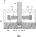
- a magnetically-responsive device generally designated 200 includes a shaft 210 to which a rotor 230 and the magnet carrier 110 are interconnected to restrain relative rotation therebetween.
- a housing 240 is positioned substantially about the shaft 210, the rotor 230, and the magnet carrier 110.
- the Hall effect sensor 120 is attached to or integrated within the housing 240.
- one or more pole 242 is attached to or integrated within the housing 240, and a magnetic field generator 245 associated with the pole 242 is spaced from the rotor 230 by a void 250.
- a magnetically responsive medium 130 such as a magnetically-responsive powder such as iron powder, is contained within and at least partially fills the void 250, including within a space separating the magnet carrier 110 from the housing 240 and the Hall effect sensor 120.
- the magnetic field generator 245 is controllable to cause the magnetically-responsive medium 130 to align along the flux path within the void 250 and thereby cause a change in torsional resistance of the rotor 230 (and the shaft 210).
- the first magnet 101 and the second magnet 105 are rotatable in a plane, wherein the first direction D1 with which the magnetic field of the first magnet 101 and the second magnet 105 is aligned is substantially orthogonal to the plane of rotation.
- the magnets are moved relative to the Hall effect sensor 120 such that changes in the flux concentration directed toward the Hall effect sensor 120 is recognized as a change in relative position between the elements.
- this change in position includes a change in proximity between the magnets and the Hall effect sensor 120, wherein the magnets are rotated to a sensing position once per rotation at which the magnets are proximal to the hall effect sensor 120.
- the Hall effect sensor 120 detects a change in the angular orientation of the magnetic field produced by the magnets, and this angular orientation is correlated to the angular position of the magnets relative to the Hall effect sensor 120.
- the improved directionality of the magnetic field compensates for a reduced field strength at the Hall effect sensor 120 caused by the magnetically-responsive medium shorting the magnetic flux path.
- one or more of the shaft 210 or elements of the magnet carrier 110 comprise magnetically-responsive materials, such as steel, such that the poles opposing the Hall effect sensor 120 are shorted, resulting in a further enhanced concentration in the direction of the Hall effect sensor 120.
- the sensor system 100 includes multiple Hall effect sensors 120. Because the present subject matter provides improved sensor functionality by increasing the directionality of the magnetic field rather than by simply increasing the strength of the magnets, the sensor system 100 is configured so as to not saturate the Hall effect sensor 120 that is proximal to the first magnet 101 and the second magnet 105. In some embodiments, this directional flux concentration further allows for better differentiation among the magnetic fields experienced at different relative positions of the first magnet 101 and the second magnet 105, which allows multiple Hall effect sensors 120 to more precisely discern the relative position of the rotating elements. In some embodiments, a first Hall effect sensor 120a and a second Hall effect sensor 120b are positioned at different relative distances with respect to first magnet 101 and second magnet 105. As illustrated in Fig.
- first Hall effect sensor 120a is positioned on a side of a printed circuit board 125 that faces towards first magnet 101 and second magnet 105
- second Hall effect sensor 120b is positioned on an opposing side of printed circuit board 125 that faces away from first magnet 101 and second magnet 105.
Landscapes
- Physics & Mathematics (AREA)
- General Physics & Mathematics (AREA)
- Transmission And Conversion Of Sensor Element Output (AREA)
- Measuring Magnetic Variables (AREA)
- Investigating Or Analyzing Materials By The Use Of Magnetic Means (AREA)
Abstract
Description
- This application claims priority to
U.S. Provisional Patent Application Serial No. 62/953,652 filed December 26, 2019 - The subject matter disclosed herein relates generally to devices, systems, and methods for measuring the angular position of a rotating system. More particularly, the subject matter disclosed herein relates to sensor systems that use Hall effect sensors.
- Non-contact sensors are useful for monitoring the position of moving components since they have few moving parts and thus generally exhibit high durability. An example of such a non-contact sensor is a Hall effect sensor, which can measure the magnitude of a magnetic field. A typical Hall effect sensor arrangement is illustrated in
Figs. 1, 2A , and2B . Such an arrangement includes asingle magnet 10 carried by amagnet carrier 11, themagnet 10 being polarized through the width of the magnet and aHall effect sensor 12 that is spaced apart from themagnet 10 in a direction that is substantially perpendicular to the direction of the magnetic field of the magnet. The effectiveness of this kind of sensor arrangement relies on themagnet 10 producing a magnetic field with sufficient rough gain to ensure sensor functionality. - In some configurations, however, such as where the
sensor magnet 10 and theHall effect sensor 12 are separated by a field of a magnetically-responsive medium 13, the magnetic flux at theHall effect sensor 12 is reduced. This reduction is illustrated in one exemplary configuration illustrated inFig. 2A . Alternatively or in addition, in some configurations, themagnet carrier 11 or other structure surrounding themagnet 10 includes other magnetically-responsive materials such as steel, which likewise acts to concentrate the magnetic flux, resulting in a reduction in the magnetic flux experienced at theHall effect sensor 12, such as is illustrated inFig. 2B . In any of these arrangements, a reduction in magnetic flux reduces the rough gain and thus the sensor magnetic performance. In addition, design limitations imposed by using magnetically-responsive material can further limit the performance of standard magnets provided or recommended by sensor manufacturers. - In accordance with this disclosure, devices for identifying the position of a movable component are provided. In one aspect, a position sensor system is provided in which a Hall effect sensor is coupled to a fixed housing, and a plurality of magnets is coupled to a movable component that is movable to a sensing position at which the plurality of magnets is proximal to the Hall effect sensor. In this configuration, the plurality of magnets is arranged to produce an aggregate magnetic field having a flux concentration directed toward the Hall effect sensor when the plurality of magnets is in the sensing position.
- In another aspect, a method for identifying the position of a movable component includes coupling a Hall effect sensor to a fixed housing, arranging a plurality of magnets on a movable component that is movable relative to the fixed housing, and moving the movable component to a sensing position at which the plurality of magnets is proximal to the Hall effect sensor, wherein the plurality of magnets is arranged to produce an aggregate magnetic field having a flux concentration directed toward the Hall effect sensor when the plurality of magnets is in the sensing position.
- Although some of the aspects of the subject matter disclosed herein have been stated hereinabove, and which are achieved in whole or in part by the presently disclosed subject matter, other aspects will become evident as the description proceeds when taken in connection with the accompanying drawings as best described hereinbelow.
- The features and advantages of the present subject matter will be more readily understood from the following detailed description which should be read in conjunction with the accompanying drawings that are given merely by way of explanatory and non-limiting example, and in which:
-
Fig. 1 is a partial side cutaway view of a conventional Hall effect sensor arrangement. -
Figs. 2A and2B are partial side cutaway views illustrating magnetic flux patterns in conventional Hall effect sensor arrangements. -
Fig. 3 is a partial side cutaway view of a Hall effect sensor arrangement according to an embodiment of the presently disclosed subject matter. -
Figs. 4A and 4B are partial side cutaway views illustrating magnetic flux patterns in Hall effect sensor arrangements according to embodiments of the presently disclosed subject matter. -
Fig. 5 is a side cutaway view of a rotary component incorporating a Hall effect sensor arrangement according to an embodiment of the presently disclosed subject matter. -
Fig. 6 is a top perspective view of a portion of a rotary component having a plurality of magnets for use in a Hall effect sensor arrangement according to an embodiment of the presently disclosed subject matter. -
Fig. 7 is a side schematic view of a Hall effect sensor arrangement according to an embodiment of the presently disclosed subject matter. - The present subject matter provides configurations for a Hall effect sensor system in which a plurality of magnets are arranged to create a more directed magnetic field having a stronger flux concentration axially in the direction of the Hall effect sensor. In some embodiments, an arrangement of multiple magnets that exhibits polarization across the length of the magnet arrangement is used in place of a single magnet that is polarized across its width. In some embodiments, this magnet arrangement includes two permanent magnets placed side by side with reversed polarity to complete the magnetic circuit.
- In one exemplary arrangement illustrated in
Fig. 3 , a sensor system, generally designated 100, includes afirst magnet 101 and asecond magnet 105 arranged next to thefirst magnet 101. Thefirst magnet 101 is arranged with afirst pole 102 oriented at least generally in a first direction D1 and asecond pole 103 oriented at least generally in a second direction D2 substantially opposite from the first direction D1. Asecond magnet 105 has afirst pole 106 oriented at least generally in the second direction D2, wherein thefirst pole 106 of thesecond magnet 105 has a polarity that matches a polarity of thefirst pole 102 of thefirst magnet 101. Thesecond magnet 105 further has asecond pole 107 that is oriented at least generally in the first direction D1, wherein thesecond pole 107 of thesecond magnet 105 has a polarity that matches a polarity of thesecond pole 103 of thefirst magnet 101. This configuration of thefirst magnet 101 and thesecond magnet 105 in a side-by-side arrangement with reversed polarities creates an aggregate magnetic field that has a shape that is somewhat similar to that of a typical sensor magnet, but the magnetic field is more concentrated in the first direction D1 and the second direction D2. - In some embodiments, the
sensor system 100 provides improved performance of a sensor configuration similar to the conventional sensor arrangement discussed above. In the configuration illustrated inFig. 3 , thefirst magnet 101 and thesecond magnet 105 are carried together by amagnet carrier 110, and aHall effect sensor 120 is spaced apart from thefirst magnet 101 and thesecond magnet 105 in the first direction D1. Themagnet carrier 110 is movable with respect to theHall effect sensor 120 to at least a sensing position at which thefirst magnet 101 and thesecond magnet 105 are proximal to theHall effect sensor 120. In some embodiments, such a sensing position is a position at which themagnet carrier 110 having thefirst magnet 101 and thesecond magnet 105 is proximal to theHall effect sensor 120 within a threshold at which theHall effect sensor 120 can be used to identify the relative position of themagnet carrier 110. In some embodiments, the first magnet and thesecond magnet 105 are positioned side-by-side in themagnet carrier 110 such that the magnets are substantially equidistant from theHall effect sensor 120 when in this proximal sensing position. - The directional concentration of the magnetic field that results from the arrangement of the
first magnet 101 and thesecond magnet 105 discussed above helps to ensure that the magnetic field at theHall effect sensor 120 has sufficient rough gain to ensure sensor functionality. This directional concentration of the magnetic field compensates for configurations that tend to cause deterioration of sensor functionality in conventional sensor systems. In some embodiments where a magnetically-responsive medium 130 is provided between theHall effect sensor 120 and the first andsecond magnets first magnet 101 and thesecond magnet 105, the magnetically-responsive medium 130 does not significantly diminish the magnetic field directed toward theHall effect sensor 120, such as is illustrated inFig. 4A . In some embodiments, the presence of other magnetically-responsive materials on a side of thesensor system 100 opposing theHall effect sensor 120 shorts the lower poles, resulting in a higher flux concentration in the direction of theHall effect sensor 120, such as is illustrated inFig. 4B . In some embodiments, this other magnetically-responsive material includes themagnet carrier 110 or one or more elements thereof being composed of steel. - In some embodiments, the present subject matter provides particular utility for devices in which the
sensor system 100 is associated with a rotating member that moves within a field of a magnetically-responsive medium. In one embodiment illustrated inFigs. 5 and6 , a magnetically-responsive device generally designated 200 includes ashaft 210 to which arotor 230 and themagnet carrier 110 are interconnected to restrain relative rotation therebetween. In some embodiments, ahousing 240 is positioned substantially about theshaft 210, therotor 230, and themagnet carrier 110. TheHall effect sensor 120 is attached to or integrated within thehousing 240. In addition, one ormore pole 242 is attached to or integrated within thehousing 240, and amagnetic field generator 245 associated with thepole 242 is spaced from therotor 230 by avoid 250. A magneticallyresponsive medium 130, such as a magnetically-responsive powder such as iron powder, is contained within and at least partially fills thevoid 250, including within a space separating themagnet carrier 110 from thehousing 240 and theHall effect sensor 120. In this arrangement, themagnetic field generator 245 is controllable to cause the magnetically-responsive medium 130 to align along the flux path within thevoid 250 and thereby cause a change in torsional resistance of the rotor 230 (and the shaft 210). - In a rotating system of this kind, the
first magnet 101 and thesecond magnet 105 are rotatable in a plane, wherein the first direction D1 with which the magnetic field of thefirst magnet 101 and thesecond magnet 105 is aligned is substantially orthogonal to the plane of rotation. In this arrangement, the magnets are moved relative to theHall effect sensor 120 such that changes in the flux concentration directed toward theHall effect sensor 120 is recognized as a change in relative position between the elements. In some embodiments, this change in position includes a change in proximity between the magnets and theHall effect sensor 120, wherein the magnets are rotated to a sensing position once per rotation at which the magnets are proximal to thehall effect sensor 120. Alternatively or in addition, in some embodiments, theHall effect sensor 120 detects a change in the angular orientation of the magnetic field produced by the magnets, and this angular orientation is correlated to the angular position of the magnets relative to theHall effect sensor 120. By using thesensor system 100 in any such configuration, the improved directionality of the magnetic field compensates for a reduced field strength at theHall effect sensor 120 caused by the magnetically-responsive medium shorting the magnetic flux path. In some embodiments, one or more of theshaft 210 or elements of themagnet carrier 110 comprise magnetically-responsive materials, such as steel, such that the poles opposing theHall effect sensor 120 are shorted, resulting in a further enhanced concentration in the direction of theHall effect sensor 120. - In some embodiments, the
sensor system 100 includes multipleHall effect sensors 120. Because the present subject matter provides improved sensor functionality by increasing the directionality of the magnetic field rather than by simply increasing the strength of the magnets, thesensor system 100 is configured so as to not saturate theHall effect sensor 120 that is proximal to thefirst magnet 101 and thesecond magnet 105. In some embodiments, this directional flux concentration further allows for better differentiation among the magnetic fields experienced at different relative positions of thefirst magnet 101 and thesecond magnet 105, which allows multipleHall effect sensors 120 to more precisely discern the relative position of the rotating elements. In some embodiments, a firstHall effect sensor 120a and a secondHall effect sensor 120b are positioned at different relative distances with respect tofirst magnet 101 andsecond magnet 105. As illustrated inFig. 7 , in some embodiments, firstHall effect sensor 120a is positioned on a side of a printedcircuit board 125 that faces towardsfirst magnet 101 andsecond magnet 105, whereas secondHall effect sensor 120b is positioned on an opposing side of printedcircuit board 125 that faces away fromfirst magnet 101 andsecond magnet 105. - Further embodiments or aspects of the present disclosure are detailed in the following numbered clauses:
- 1. A position sensor system comprising: a Hall effect sensor coupled to a fixed housing; and a plurality of magnets coupled to a movable component that is movable to a sensing position at which the plurality of magnets is proximal to the Hall effect sensor; wherein the plurality of magnets is arranged to produce an aggregate magnetic field having a flux concentration directed toward the Hall effect sensor when the plurality of magnets is in the sensing position.
- 2. The position sensor system of clause 1, wherein the plurality of magnets comprises: a first magnet arranged with a first pole oriented in a first direction facing the Hall effect sensor and a second pole oriented in a second direction substantially opposing the first direction; and a second magnet arranged next to the first magnet, the second magnet having a first pole oriented in the second direction and a second pole oriented in the first direction; wherein the first pole of the first magnet and the first pole of the second magnet have the same polarity; and wherein the second pole of the first magnet and the second pole of the second magnet have the same polarity.
- 3. The position sensor system of clause 1, wherein the plurality of magnets is rotatable in a plane; and wherein the Hall effect sensor is spaced apart from the movable component in a direction substantially orthogonal to the plane in which the movable component is movable.
- 4. The position sensor system of clause 1, wherein the plurality of magnets are arranged next to each other on a magnet carrier attached to the movable component.
- 5. The position sensor system of clause 4, wherein the magnet carrier comprises one or more elements composed of a magnetically-responsive material.
- 6. The position sensor system of clause 1, comprising a magnetically-responsive medium positioned between the plurality of magnets and the Hall effect sensor.
- 7. A position sensor system comprising: a Hall effect sensor coupled to a fixed housing; a magnet carrier coupled to a movable component that is rotatable within the fixed housing; a magnetically-responsive medium positioned between the magnet carrier and the Hall effect sensor; and a plurality of magnets arranged next to each other on the magnet carrier, the plurality of magnets being movable to a sensing position at which the plurality of magnets is proximal to the Hall effect sensor; wherein the plurality of magnets is arranged to produce an aggregate magnetic field having a flux concentration directed toward the Hall effect sensor when the plurality of magnets is in the sensing position.
- 8. The position sensor system of clause 7, wherein the magnet carrier comprises one or more elements composed of a magnetically-responsive material.
- 9. The position sensor system of clause 7, wherein the plurality of magnets comprises: a first magnet arranged with a first pole oriented in a first direction facing the Hall effect sensor and a second pole oriented in a second direction substantially opposing the first direction; and a second magnet arranged next to the first magnet, the second magnet having a first pole oriented in the second direction and a second pole oriented in the first direction; wherein the first pole of the first magnet and the first pole of the second magnet have the same polarity; and wherein the second pole of the first magnet and the second pole of the second magnet have the same polarity.
- 10. A method for identifying the position of a movable component, the method comprising: coupling a Hall effect sensor to a fixed housing; arranging a plurality of magnets on a movable component that is movable relative to the fixed housing; and moving the movable component to a sensing position at which the plurality of magnets is proximal to the Hall effect sensor, wherein the plurality of magnets is arranged to produce an aggregate magnetic field having a flux concentration directed toward the Hall effect sensor when the plurality of magnets is in the sensing position.
- 11. The method of
clause 10, wherein arranging the plurality of magnets on the movable component comprises: arranging a first magnet with a first pole oriented in a first direction facing the Hall effect sensor and a second pole oriented in a second direction substantially opposing the first direction; and arranging a second magnet next to the first magnet, the second magnet having a first pole oriented in the second direction and a second pole oriented in the first direction; wherein the first pole of the first magnet and the first pole of the second magnet have the same polarity; and wherein the second pole of the first magnet and the second pole of the second magnet have the same polarity. - 12. The method of
clause 10, wherein moving the movable component comprising rotating the movable component in a plane; wherein the Hall effect sensor is spaced apart from the movable component in a direction substantially orthogonal to the plane in which the movable component is movable. - 13. The method of
clause 10, wherein arranging the plurality of magnets on the movable component comprising arranging the plurality of magnets next to each other on a magnet carrier attached to the movable component. - 14. The method of
clause 13, wherein the magnet carrier comprises one or more elements composed of a magnetically-responsive material. - 15. The method of
clause 10, comprising inserting a magnetically-responsive medium between the plurality of magnets and the Hall effect sensor. - The present subject matter can be embodied in other forms without departure from the spirit and essential characteristics thereof. The embodiments described therefore are to be considered in all respects as illustrative and not restrictive. Although the present subject matter has been described in terms of certain preferred embodiments, other embodiments that are apparent to those of ordinary skill in the art are also within the scope of the present subject matter.
Claims (15)
- A magnetically-responsive device (200) comprising:a fixed housing (240) having a void (250) defined therein;a movable component that is rotatable relative to the fixed housing (240) and comprises a shaft (210), a rotor (230), and a magnet carrier (110);a Hall effect sensor (120) coupled to the fixed housing (240);a plurality of magnets (101, 105) coupled to the magnet carrier (110), so as to be rotatable relative to the fixed housing (240);one or more poles (242) attached to or integrated within the fixed housing (240); anda magnetically responsive material (130) is contained within and at least partially fills the void (250);a magnetic field generator (245) associated with the one or more poles (242), wherein the magnetic field generator (245) is spaced from the rotor (230) by the void (250);wherein the magnet carrier (110) is configured to position the plurality of magnets (101, 105) in a sensing position, at which the plurality of magnets (101, 105) is proximal to the Hall effect sensor (120);wherein the plurality of magnets (101, 105) is arranged to produce an aggregate magnetic field having a flux concentration directed toward the Hall effect sensor (120) when the plurality of magnets (101, 105) is in the sensing position; andwherein the magnetic field generator (245) is controllable to cause the magnetically responsive material (130) to cause a change in torsional resistance of the rotor (230) and the shaft (210).
- The magnetically-responsive device of claim 1, wherein the shaft (210), the rotor (230), and the magnet carrier (110) are interconnected to restrain relative rotation therebetween.
- The magnetically-responsive device of claim 1, wherein the fixed housing (240) is positioned about the shaft (210), the rotor (230), and the magnet carrier (110).
- The magnetically-responsive device of claim 1, wherein the Hall effect sensor (120) is attached to or integrated within the fixed housing (240).
- The magnetically-responsive device of claim 1, wherein the magnetically responsive medium (130) comprises a magnetically-responsive powder.
- The magnetically-responsive device of claim 5, wherein the magnetically-responsive powder comprises iron powder.
- The magnetically-responsive device of claim 1, wherein the magnetically responsive material (130) is contained within a space within the void (250) that separates the magnet carrier (110) from the fixed housing (240) and the Hall effect sensor (120).
- The magnetically-responsive device of claim 1, wherein the magnetic field generator (245) causes the magnetically responsive material (130) to align along a flux path within the void (250) to cause the change in torsional resistance of the rotor (230) and the shaft (210).
- The magnetically-responsive device of claim 1, wherein:the plurality of magnets (101, 105) comprises a first magnet (101) and a second magnet (105); andthe first magnet (101) and the second magnet (105) are rotatable in a plane.
- The magnetically-responsive device of claim 9, wherein the aggregate magnetic field produced by the first magnet (101) and the second magnet (105) is substantially orthogonal to the plane in which the first magnet (101) and the second magnet (105) are rotatable.
- The magnetically-responsive device of claim 9, wherein, as the first and second magnets (101, 105) are moved relative to the Hall effect sensor (120), the Hall effect sensor (120) is configured to detect changes in flux concentration as a change in relative position between the first and second magnets (101, 105) and the Hall effect sensor (120).
- The magnetically-responsive device of claim 11, wherein the change in relative position between the first and second magnets (101, 105) and the Hall effect sensor (120) includes a change in proximity between the first and second magnets (101, 105) and the Hall effect sensor (120).
- The magnetically-responsive device of claim 12, wherein the first and second magnets (101, 105) are rotated to a sensing position once per rotation of the shaft (210) and, in the sensing position, the first and second magnets (101, 105) are proximal to the Hall effect sensor (120).
- The magnetically-responsive device of claim 9, wherein the Hall effect sensor (120) is configured to detect a change in an angular orientation of the aggregate magnetic field produced by the first and second magnets (101, 105), the angular orientation of the aggregate magnetic field being correlated to an angular position of the first and second magnets (101, 105) relative to the Hall effect sensor.
- The magnetically-responsive device of claim 1, wherein the shaft (210) and/or the magnet carrier (110) comprise magnetically-responsive material, optionally, wherein the magnetically-responsive material comprises steel.
Applications Claiming Priority (3)
| Application Number | Priority Date | Filing Date | Title |
|---|---|---|---|
| US201962953652P | 2019-12-26 | 2019-12-26 | |
| EP20842516.5A EP4081760B1 (en) | 2019-12-26 | 2020-12-22 | Sensor arrangement having a dual magnet |
| PCT/US2020/066626 WO2021133808A1 (en) | 2019-12-26 | 2020-12-22 | Sensor arrangement having a dual magnet |
Related Parent Applications (1)
| Application Number | Title | Priority Date | Filing Date |
|---|---|---|---|
| EP20842516.5A Division EP4081760B1 (en) | 2019-12-26 | 2020-12-22 | Sensor arrangement having a dual magnet |
Publications (2)
| Publication Number | Publication Date |
|---|---|
| EP4571265A2 true EP4571265A2 (en) | 2025-06-18 |
| EP4571265A3 EP4571265A3 (en) | 2025-08-27 |
Family
ID=74186975
Family Applications (2)
| Application Number | Title | Priority Date | Filing Date |
|---|---|---|---|
| EP25174338.1A Pending EP4571265A3 (en) | 2019-12-26 | 2020-12-22 | Sensor arrangement having a dual magnet |
| EP20842516.5A Active EP4081760B1 (en) | 2019-12-26 | 2020-12-22 | Sensor arrangement having a dual magnet |
Family Applications After (1)
| Application Number | Title | Priority Date | Filing Date |
|---|---|---|---|
| EP20842516.5A Active EP4081760B1 (en) | 2019-12-26 | 2020-12-22 | Sensor arrangement having a dual magnet |
Country Status (5)
| Country | Link |
|---|---|
| US (1) | US12601613B2 (en) |
| EP (2) | EP4571265A3 (en) |
| CN (2) | CN114846300A (en) |
| DK (1) | DK4081760T3 (en) |
| WO (1) | WO2021133808A1 (en) |
Families Citing this family (2)
| Publication number | Priority date | Publication date | Assignee | Title |
|---|---|---|---|---|
| US11846529B2 (en) | 2021-04-19 | 2023-12-19 | Joral Llc | Magnetic rack and pinion linear magnetic encoder and position sensing system |
| US12504300B2 (en) * | 2023-06-30 | 2025-12-23 | Azena Medical, LLC | Devices with hall effect user interface control |
Family Cites Families (19)
| Publication number | Priority date | Publication date | Assignee | Title |
|---|---|---|---|---|
| US5444369A (en) | 1993-02-18 | 1995-08-22 | Kearney-National, Inc. | Magnetic rotational position sensor with improved output linearity |
| CN101382440B (en) * | 2003-02-21 | 2010-12-08 | 费希尔控制产品国际有限公司 | Magnetic Position Sensor with Integrated Hall Effect Switches |
| US6836111B2 (en) * | 2003-04-03 | 2004-12-28 | Delphi Technologies, Inc. | Sensor assembly with a universal sensor module for sensing angular position of an object |
| US6992478B2 (en) * | 2003-12-22 | 2006-01-31 | Cts Corporation | Combination hall effect position sensor and switch |
| US7088095B1 (en) * | 2004-02-04 | 2006-08-08 | Honeywell International Inc. | Balanced magnetic linear displacement sensor |
| US7208943B2 (en) * | 2005-06-03 | 2007-04-24 | Delphi Technologies, Inc. | Electrical device enclosure |
| DE102008028967A1 (en) * | 2007-07-27 | 2009-02-19 | Continental Teves Ag & Co. Ohg | Method for determining the tread depth of a tire and / or a tire property and tires |
| US8087305B2 (en) * | 2009-05-15 | 2012-01-03 | Infineon Technologies Ag | System including a magnet and first and second concentrators |
| DE102009048389B4 (en) | 2009-10-06 | 2019-12-19 | Asm Automation Sensorik Messtechnik Gmbh | Arrangement for detection of more than one revolution using magnets as a position transmitter |
| CH702193A2 (en) * | 2009-11-05 | 2011-05-13 | Polycontact Ag | Position signaling device. |
| KR101300353B1 (en) * | 2011-12-22 | 2013-08-28 | 삼성전기주식회사 | Hand vibration correction device |
| DE102016100499A1 (en) * | 2016-01-13 | 2017-07-13 | Fraba B.V. | Arrangement of a rotation angle measuring system on a housing |
| DE102017202374A1 (en) * | 2016-02-19 | 2017-08-24 | Volkswagen Aktiengesellschaft | DEVICE AND METHOD FOR DETERMINING A SWITCHING OF A GEARBOX |
| CN108496300B (en) * | 2016-02-22 | 2022-05-27 | 深圳市大疆灵眸科技有限公司 | Motor position sensing |
| JP6746378B2 (en) * | 2016-05-27 | 2020-08-26 | 東洋電装株式会社 | Magnetic rotation detector |
| EP3504775A1 (en) * | 2016-08-23 | 2019-07-03 | LORD Corporation | Magnetic seal for magnetically-responsive devices, systems, and methods |
| CN110573829A (en) * | 2016-12-22 | 2019-12-13 | 哈姆林电子(苏州)有限公司 | Magnetic Position Sensor |
| EP3795955B1 (en) * | 2019-09-23 | 2023-01-04 | Melexis Technologies SA | Magnetic position sensor system |
| US11846529B2 (en) * | 2021-04-19 | 2023-12-19 | Joral Llc | Magnetic rack and pinion linear magnetic encoder and position sensing system |
-
2020
- 2020-12-22 US US17/781,176 patent/US12601613B2/en active Active
- 2020-12-22 EP EP25174338.1A patent/EP4571265A3/en active Pending
- 2020-12-22 DK DK20842516.5T patent/DK4081760T3/en active
- 2020-12-22 WO PCT/US2020/066626 patent/WO2021133808A1/en not_active Ceased
- 2020-12-22 CN CN202080089084.4A patent/CN114846300A/en active Pending
- 2020-12-22 CN CN202411031618.4A patent/CN118936521A/en active Pending
- 2020-12-22 EP EP20842516.5A patent/EP4081760B1/en active Active
Also Published As
| Publication number | Publication date |
|---|---|
| EP4571265A3 (en) | 2025-08-27 |
| US20230003551A1 (en) | 2023-01-05 |
| CA3161797A1 (en) | 2021-07-01 |
| WO2021133808A1 (en) | 2021-07-01 |
| CN118936521A (en) | 2024-11-12 |
| EP4081760A1 (en) | 2022-11-02 |
| US12601613B2 (en) | 2026-04-14 |
| CN114846300A (en) | 2022-08-02 |
| EP4081760B1 (en) | 2025-05-07 |
| DK4081760T3 (en) | 2025-07-14 |
Similar Documents
| Publication | Publication Date | Title |
|---|---|---|
| KR100318230B1 (en) | Hall Effect Ferromagnetic Proximity Sensor | |
| DE69123240T2 (en) | MAGNETIC POSITION AND SPEED SENSOR WITH HALL PROBE | |
| US6922052B2 (en) | Measuring device for contactless detecting a ferromagnetic object | |
| EP1538448A1 (en) | Eddy current sensors | |
| US9052185B2 (en) | Rotation detecting device | |
| US10209096B2 (en) | Rotation detecting device | |
| EP2549236B1 (en) | Stationary magnet variable reluctance magnetic sensors | |
| EP4081760B1 (en) | Sensor arrangement having a dual magnet | |
| DE102009033242A1 (en) | Torque sensor arrangement with rotation angle index detection | |
| US20090001970A1 (en) | Magnetic encoder | |
| KR20140015323A (en) | Rotation angle detection device | |
| US8030917B2 (en) | Over one turn rotation angle sensor using rotating magnetic field | |
| US20100176801A1 (en) | Magnetic encoder | |
| CA3161797C (en) | Sensor arrangement having a dual magnet | |
| JP2010145371A (en) | Angle detection apparatus | |
| KR20190043276A (en) | Resolver stator | |
| US7151369B1 (en) | Position sensor | |
| JP2004037236A (en) | Rotation angle detector | |
| KR102476480B1 (en) | Rotor and Motor having the same | |
| EP4707747A1 (en) | Motion detection device | |
| US12216138B2 (en) | Rotation speed detector | |
| JPH07294540A (en) | Magnetism detection device | |
| CN121127729A (en) | Rotary detection device | |
| KR20150135595A (en) | Power steering torque sensor for a vehicle | |
| CN101341383A (en) | Sensor system including magnetized axis |
Legal Events
| Date | Code | Title | Description |
|---|---|---|---|
| PUAI | Public reference made under article 153(3) epc to a published international application that has entered the european phase |
Free format text: ORIGINAL CODE: 0009012 |
|
| STAA | Information on the status of an ep patent application or granted ep patent |
Free format text: STATUS: THE APPLICATION HAS BEEN PUBLISHED |
|
| AC | Divisional application: reference to earlier application |
Ref document number: 4081760 Country of ref document: EP Kind code of ref document: P |
|
| AK | Designated contracting states |
Kind code of ref document: A2 Designated state(s): AL AT BE BG CH CY CZ DE DK EE ES FI FR GB GR HR HU IE IS IT LI LT LU LV MC MK MT NL NO PL PT RO RS SE SI SK SM TR |
|
| PUAL | Search report despatched |
Free format text: ORIGINAL CODE: 0009013 |
|
| AK | Designated contracting states |
Kind code of ref document: A3 Designated state(s): AL AT BE BG CH CY CZ DE DK EE ES FI FR GB GR HR HU IE IS IT LI LT LU LV MC MK MT NL NO PL PT RO RS SE SI SK SM TR |
|
| RIC1 | Information provided on ipc code assigned before grant |
Ipc: G01D 5/14 20060101AFI20250722BHEP |
|
| P01 | Opt-out of the competence of the unified patent court (upc) registered |
Free format text: CASE NUMBER: UPC_APP_1367_4571265/2025 Effective date: 20250729 |
|
| STAA | Information on the status of an ep patent application or granted ep patent |
Free format text: STATUS: REQUEST FOR EXAMINATION WAS MADE |
|
| 17P | Request for examination filed |
Effective date: 20251112 |
|
| GRAP | Despatch of communication of intention to grant a patent |
Free format text: ORIGINAL CODE: EPIDOSNIGR1 |
|
| STAA | Information on the status of an ep patent application or granted ep patent |
Free format text: STATUS: GRANT OF PATENT IS INTENDED |
|
| INTG | Intention to grant announced |
Effective date: 20260320 |