EP4571238A1 - Bullet feeder - Google Patents
Bullet feeder Download PDFInfo
- Publication number
- EP4571238A1 EP4571238A1 EP24152919.7A EP24152919A EP4571238A1 EP 4571238 A1 EP4571238 A1 EP 4571238A1 EP 24152919 A EP24152919 A EP 24152919A EP 4571238 A1 EP4571238 A1 EP 4571238A1
- Authority
- EP
- European Patent Office
- Prior art keywords
- rotary ring
- bullet
- bullets
- static support
- drive
- Prior art date
- Legal status (The legal status is an assumption and is not a legal conclusion. Google has not performed a legal analysis and makes no representation as to the accuracy of the status listed.)
- Granted
Links
Images



Classifications
-
- F—MECHANICAL ENGINEERING; LIGHTING; HEATING; WEAPONS; BLASTING
- F42—AMMUNITION; BLASTING
- F42B—EXPLOSIVE CHARGES, e.g. FOR BLASTING, FIREWORKS, AMMUNITION
- F42B33/00—Manufacture of ammunition; Dismantling of ammunition; Apparatus therefor
- F42B33/002—Orienting or guiding means for cartridges or cartridge parts during the manufacturing or packaging process; Feeding cartridge elements to automatic machines
Definitions
- the object of the invention is a bullet feeder for use in ammunition reloading devices.
- the feeder of the invention sorts the bullets from a bullet hopper so that the incorrectly oriented bullets fall back into the container by gravity and the correctly oriented bullets move along a guide by gravity to a bullet feeder die.
- the bullet must always be inserted correctly into a case, so that the rear of the bullet enters the case first.
- the bullet is usually substantially cylindrical in shape and has a substantially conically shaped head (apex), the head diameter gradually tapering towards the apex, and a rear portion shaped substantially as a flat surface.
- the feeder of the invention with its appropriately shaped pockets and sorting bridge, exploits the shape of the bullet to position it correctly in the position of insertion.
- the bullet feeder of the invention can be easily adapted to different calibres and shapes of bullets having a substantially conical apex, such as round nose, flat nose, sharp tip, hollow point, insertion tip, soft point, semi wadcutter.
- Ammunition reloading started years ago in an effort by shooters to make their own ammunition instead of being satisfied with the ammunition on sale. So, many professional and amateur sport shooting competitors load ammunition at home, mainly because of more accurate and consistent loading, and because it is cheaper. Spent cases are collected and reloaded. Ammunition reloading is useful for many types of ammunition, especially for ammunition consisting of a cartridge case, primer, powder and bullet. As a lot of ammunition can be used for training, it pays to load ammunition at home. In addition, home-loaded ammunition can be of higher quality than store-bought ammunition, which is reflected in better results in training and competitions.
- US 7552668 describes a bullet feeder having a rotary ring with pockets for receiving bullets from a container, wherein the pockets are formed in a way that their diameter is tapered in a radial direction towards the interior of the ring to allow only the correctly oriented bullets to enter the pocket with their full length, while the incorrectly oriented bullets protrude out of the pocket with their apex and are removed from the pocket when they strike a boss during the movement of the rotary ring, which pushes the incorrectly oriented bullet out of the pocket.
- a disadvantage of this feeder is that it cannot be used for several different cartridge calibres without major modifications.
- US 8661959 and US 10907945 describe a bullet-orienting system comprising a conveyor ring with grooves for receiving bullets, which conveys the bullets from a container to a feed tube, and comprising a bullet-orienting structure positioned along a bullet conveyance path, which flips the bullets which are misoriented in the grooves 180 degrees so that when they reach the opening by rotation of the transport ring, they are correctly oriented and can enter the outlet tube through the opening.
- a disadvantage of this system is its many components. In addition, said system does not allow the use for a wide range of calibres without changing the conveyor ring.
- the bullet feeder of the invention which can be used for comparable calibres (e.g. 9 mm and 10 mm) and bullet shapes with an essentially conical apex, without adjustments to the rotary ring, the feeder being compact and inexpensive and can be used on commercially available ammunition reloading devices.
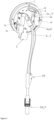
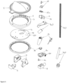
- the bullet feeder of the invention comprises a static support 1, a rotary ring 2 provided with pockets 3 for receiving bullets 4, a container 5 for bullets 4, a sorting bridge 6, a guide 7 for conveying the correctly oriented bullets 4 to a die 40 for inserting bullets 4 into a cartridge case (not shown in figure) and a drive 8 of the rotary ring 2.
- the static support 1 is designed to hold the individual components of the bullet feeder in such a way as to allow them to interact with each other, as will be described below.
- the rotary ring 2 is pivotally fixable with respect to the static support 1.
- the pivotal fixation is implemented by inserting the rotary ring 2 into the space between the container 5 and the static support 1, wherein the container 5 is fixed to the static support 1 and the required distance of the container 5 from the static support 1 for forming the intermediate space, into which the rotary ring 2 is inserted and is allowed to rotate, is formed by means of a support bracket 9 and at least one spacer 10, preferably two spacers 10.
- the support bracket 9 and the spacers 10 provide a fixed connection between the container 5 and the static support 1, while at the same time providing an empty intermediate space into which the rotary ring 2 is inserted.
- the rotary ring 2 may be positioned vertically, so that its axis of rotation is horizontal, or the rotary ring 2 may be tilted backwards from the vertical by a certain angle, i.e. away from the container 5, so that its axis of rotation is tilted backwards from the horizontal by a certain angle.
- the tilting of the rotary ring 2 is implemented by at least one support member 11 fixed to a rear surface 1a of the static support 1, to a surface facing away from the container 5.
- the tilting of the rotary ring 2 is implemented via two support members 11.
- the pockets 3 for receiving bullets 4 are formed around an inner circumference 2a of the rotary ring 2 in such a way that an inlet opening 3a of a respective pocket 3, through which a bullet 4 can enter the pocket 3, faces the axis of rotation of the rotary ring 2.
- the pockets 3 extend into the interior of the rotary ring 2 substantially in the radial direction with respect to the rotary ring 2 or at a certain angle ⁇ with respect to the radial direction.
- the configuration of the pockets 3 being at an angle with respect to the radial direction ensures that a bullet 4 subsequently falls out of the pocket 3, thus preventing the bullet 4 from falling out of the pocket 3 before the pocket 3 enters the area of the sorting bridge 6, while at the same time allowing the sorting bridge 6 to be mounted in a higher position, i.e. higher up around the inner circumference 2a of the rotary ring 2 in its upper part, and the bullet feeder may be of smaller dimensions.
- the diameter R of a respective pocket 3 is essentially the same throughout its depth and is greater than the diameter of a bullet 4, so that a bullet 4 can easily enter the pocket 3 either with its apex or its rear portion, but smaller than the length of a bullet 4, so that a bullet 4 can only be positioned in the pocket 3 longitudinally and not transversely.
- the depth of the pocket 3 is at least such that a bullet 4 can enter substantially completely into the pocket 3 along its length.
- the pockets 3 are equidistantly arranged around the inner circumference 2a of the rotary ring 2.
- the diameter R of a respective pocket 3 is dimensioned in such a way that the bullet feeder can be used for comparable calibre bullets, for example 9 mm and 10 mm calibre bullets, without changing the rotary ring 2, while at the same time providing sufficient tolerance to allow a bullet 4 to move when in the pocket 3.
- the inlet into the opening 3a of a respective pocket 3 in the portion facing the direction of rotation of the rotary ring 2 is formed by a chamfer 3b.
- the chamfer 3b allows for better mixing of the bullets 4 in the container 5 when the rotary ring 2 is rotating and facilitates the entry of the bullets 4 into the pockets 3. Otherwise, it may happen that the bullets 4 are stuck in some static position and none of them fall into the pocket 3, even though the rotary ring 2 is rotating.
- the container 5 is fixed to a front face 1b of the static support 1 in such a way that it is located under the entire rotary ring 2, so that a bullet 4 falling out of the pocket 3 can fall back into the container 5.
- a front wall 5a of the container 5 covers at least the lower portion of the rotary ring 2, which is inserted between the container 5 and the static support 1, on its front side.
- the rotary ring 2 passes through the lowest portion of the container 5 in such a way that the openings 3a of the pockets 3 face the interior of the container 5, so that the bullets 4 contained in the container 5 can fall into the pockets 3 due to gravity and possible interaction with each other.
- the height of the container 5 from the bottom to the top edge is chosen to accommodate a desired number of bullets 4 and to prevent the bullets 4 from falling out of the container 5 due to the interaction with each other and the rotation of the rotary ring 2.
- the front wall 5a of the container 5 is optionally transparent to show how many bullets 4 are contained in the container 5.
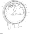
- the sorting bridge 6 is movably mounted on the static support 1 around the inner circumference 2a of the rotary ring 2 in its upper portion, extending from the portion where the bullets 4 would fall out of the pockets 3 due to gravity and terminating at an inlet 7a into the guide 7.
- the movable placement of the sorting bridge 6 on the static support 1 is implemented by a slot 1c provided in the static support 1, through which the sorting bridge 6 is inserted, and an adjusting screw 12 adapted to move the sorting bridge 6 in the slot 1c in a direction parallel to the axis of rotation of the rotary ring 2.
- the dimensions of the slot 1c are adapted to the dimensions of the sorting bridge 6 so that rotation of the adjusting screw 12 in one direction or the other (i.e. clockwise or anticlockwise) enables the sorting bridge 6 in the slot 1c to be moved forwards or backwards, respectively (i.e. in a direction parallel to the axis of rotation of the rotary ring 2).
- the sorting bridge 6 extends with its upper surface 6a, i.e. the surface facing the inlet openings 3a, over part of the inlet openings 3a of the pockets 3, or by how much the sorting bridge 6 extends above the inner face 1b of the static support 1, i.e. to adjust the width of the overlap by which the sorting bridge 6 partially overlaps the inlet openings 3a.
- the movable placement thus allows the sorting bridge 6, by partially covering the inlet openings 3a of the pockets 3, to prevent a bullet 4 from falling out of the pocket 3 due to gravity when the pocket 3 in the upper portion of the rotary ring 2 passes over the sorting bridge 6, when a bullet 4 in the pocket 3 is correctly oriented, i.e.
- the adjusting screw 12 may be provided with a cover 12a with a visual mark indicating the direction of movement of the sorting bridge 6 in the slot 1c forward and backward, or outward and inward relative to the front face 1b.
- the upper surface 6a of the sorting bridge 6 is stepped to allow a correctly oriented bullet 4 to abut on a step 6b with its rear portion, i.e. with its rear surface which is essentially a flat surface, to further prevent the correctly oriented bullet 4 from falling from the sorting bridge 6 or from the pocket 3 as it travels over the sorting bridge 6.
- the bullet feeder of the invention with its appropriately shaped pockets 3 and sorting bridge 6, exploits the shape of the bullet 4 to position it correctly in the position of insertion.
- the bullet 4 with its rear surface which is essentially a flat surface, abuts on the upper surface 6a of the sorting bridge 6, thereby enabling the correctly oriented bullet 4 not to fall out of the pocket 3 and thus off the sorting bridge 6 when the pocket 3 passes over the sorting bridge 6 in the upper portion of the rotary ring 2.
- an incorrectly oriented bullet 4 with its apex which is essentially conical in shape, does not abut on the upper surface 6a of the sorting bridge 6 and therefore falls out of the pocket 3 and thus off the sorting bridge 6 when the pocket 3 passes over the sorting bridge 6 in the upper portion of the rotary ring 2.
- the bullet feeder to be adapted to different comparable calibres and shapes of bullets 4, which have their apex substantially conical in shape.
- the width of the overlap by which the sorting bridge 6 partially covers the inlet openings 3a is slightly greater than for smaller calibres.
- the guide 7 for conveying the correctly oriented bullets 4 to the die 40 for inserting bullets 4 into a cartridge case comprises an inlet 7a of the guide 7 and an outlet 7b of the guide 7, wherein the inlet 7a of the guide 7 is positioned below substantially the highest point of rotation of the inner circumference 2a of the rotary ring 2 and is fixed to the front face 1b of the static support 1, so that a correctly oriented bullet 4 from the pocket 3 falls by gravity into the inlet 7a of the guide 7 and travels along the guide 7 to the outlet 7b of the guide 7.
- the outlet 7b of the guide 7 is fixable to the die 40 for inserting the bullets 4 into the cartridge case.
- the diameter of the guide 7, including the inlet 7a and the outlet 7b, is such as to allow the bullet 4 to be moved along it by gravity.
- the diameter of the guide 7 is thus greater than the diameter of the bullet 4 but smaller than the length of the bullet 4 to prevent the bullet 4 from turning and possibly jamming as it travels from the inlet 7a to the outlet 7b of the guide 7.
- a drive 8 of the rotary ring 2 is fixed with respect to the static support 1 and is coupled to the rotary ring 2 in terms of drive to ensure that the rotary ring 2 rotates in a defined direction at a defined speed.
- the drive 8 is configured as an electric motor with a suitable power supply, for example a battery or other suitable voltage source.
- the attachment of the drive 8 is by means of a holder 8a of the drive 8, which is attached to the rear face 1a of the static support 1.
- a drive connection is made via gears 8b and an axle 8c of the drive 8, wherein one gear is mounted on the axle 8c of the drive 8 and the other gear is mounted on the rotary ring 2.
- the holder 8a of the drive 8 is provided with a pin 8d which allows the contact between the two gears 8b to be manually disengaged, thereby allowing manipulation in the bullet feeder if necessary.
- the guide 7 optionally comprises a sensor connected to a switch 13 for switching the drive 8 of the rotary ring 2 on/off.
- the sensor detects that the height of the bullets 4 in the guide 7 has reached a predetermined height
- the sensor transmits a corresponding signal to the drive 8 which switches off.
- the sensor detects that the height of the bullets 4 in the guide 7 has fallen under a predetermined height
- the sensor transmits a corresponding signal to the drive 8 which switches on again. In this way, the blockage of the guide 7 is prevented.
- the static support 1 consists of a stand 20 and a central plate 30 which is detachably fixable to the stand 20 by means of support members 11, and the individual components of the bullet feeder are attached to the central plate 30 in such a way that their mutual interaction is made possible as previously described.
- the bullet feeder comprises a static support 1 consisting of a stand 20 and a central plate 30 which is detachably fixable to the stand 20, in the instant embodiment the case feeder, by means of two support members 11.
- the individual components of the bullet feeder are fixed to the central plate 30.
- the rotary ring 2 is inserted between the container 5 and the central plate 30, the container 5 being fixed to the central plate 30.
- the required distance of the container 5 from the central plate 30 to form the intermediate space into which the rotary ring 2 is inserted is implemented by means of a support bracket 9 and two spacers 10.
- the rotary ring 2 is inclined by an angle of 20 degrees from the vertical backwards, the inclination of the rotary ring 2 being implemented via two support members 11 fixed to the rear face 1a of the central plate 30.
- the pockets 3 for receiving bullets 4 are provided around the inner circumference 2a of the rotary ring 2 and extend into the interior of the rotary ring 2 at an angle ⁇ of 30 degrees with respect to the radial direction. Entry into the opening 3a of a respective pocket 3 in the portion facing the direction of rotation of the rotary ring 2 is formed by a chamfer 3b.
- the container 5 is fixed to a front face 1b of the central plate 30 in such a way that it is located under the entire rotary ring 2.
- the movable placement of the sorting bridge 6 on the central plate 30 is implemented by a slot 1c provided in the central plate 30 and an adjusting screw 12.
- the rotation of the adjusting screw 12 in one direction or the other (clockwise or anticlockwise) enables setting the width of overlapping, with which the sorting bridge 6 partially covers the inlet opening 3a.
- the upper surface 6a of the sorting bridge 6 is stepped.
- the bullet feeder in this embodiment is adapted to calibres of 9 mm and 0.40 inch for the round nose shape of the apex of the bullet 4.
- the guide 7 for conveying the correctly oriented bullets 4 to the die 40 for inserting bullets 4 into a cartridge case is formed of a flexible tube 7c, while the inlet 7a of the guide 7 and the outlet 7b of the guide 7 are formed as stiff elements.
- the inlet 7a of the guide 7 is fixed to the front face 1b of the central plate 30 below substantially the highest point of rotation of the inner circumference 2a of the rotary ring 2, so that a correctly oriented bullet 4 from the pocket 3 falls by gravity into the inlet 7a of the guide 7 and travels along the flexible tube 7c to the outlet 7b of the guide 7.
- the outlet 7b of the guide 7 is fixable to the die 40 for inserting the bullets 4 into the cartridge case.
- the drive 8 of the rotary ring 2 is fixed with respect to the central plate 30 and configured as an electric motor. The attachment of the electric motor 8 is by means of a holder 8a which is attached to the rear face 1b of the central plate 30.
- a drive connection is made via gears 8b and an axle 8c of the electric motor 8, wherein one gear is mounted on the axle 8c of the electric motor 8 and the other gear is mounted on the rotary ring 2.
- the holder 8a of the electric motor 8 is provided with a pin 8c which allows the contact between the two gears 8b to be manually disengaged, thereby allowing manipulation in the bullet feeder if necessary.
- the guide 7 comprises a sensor connected to a switch 13 for switching the electric motor 8 of the rotary ring 2 on/off. When the sensor detects that the height of the bullets 4 in the guide 7 has reached a predetermined height, the sensor transmits a corresponding signal to the electric motor 8 which switches off. When the sensor detects that the height of the bullets 4 in the guide 7 has fallen under a predetermined height, the sensor transmits a corresponding signal to the electric motor 8 which switches on again. In this way, the blockage of the guide 7 is prevented.
Landscapes
- Engineering & Computer Science (AREA)
- Manufacturing & Machinery (AREA)
- General Engineering & Computer Science (AREA)
- Feeding Of Articles To Conveyors (AREA)
Abstract
Description
- The object of the invention is a bullet feeder for use in ammunition reloading devices. The feeder of the invention sorts the bullets from a bullet hopper so that the incorrectly oriented bullets fall back into the container by gravity and the correctly oriented bullets move along a guide by gravity to a bullet feeder die. The bullet must always be inserted correctly into a case, so that the rear of the bullet enters the case first. The bullet is usually substantially cylindrical in shape and has a substantially conically shaped head (apex), the head diameter gradually tapering towards the apex, and a rear portion shaped substantially as a flat surface. The feeder of the invention, with its appropriately shaped pockets and sorting bridge, exploits the shape of the bullet to position it correctly in the position of insertion. Due to the specific shape and positioning of the sorting bridge, the bullet feeder of the invention can be easily adapted to different calibres and shapes of bullets having a substantially conical apex, such as round nose, flat nose, sharp tip, hollow point, insertion tip, soft point, semi wadcutter.
- Ammunition reloading started years ago in an effort by shooters to make their own ammunition instead of being satisfied with the ammunition on sale. So, many professional and amateur sport shooting competitors load ammunition at home, mainly because of more accurate and consistent loading, and because it is cheaper. Spent cases are collected and reloaded. Ammunition reloading is useful for many types of ammunition, especially for ammunition consisting of a cartridge case, primer, powder and bullet. As a lot of ammunition can be used for training, it pays to load ammunition at home. In addition, home-loaded ammunition can be of higher quality than store-bought ammunition, which is reflected in better results in training and competitions.
- Until the mid-1970s, most companies in the ammunition reloading industry produced only handoperated reloading products, which allowed only one cartridge case to be reloaded at a time, which was very time-consuming. With a rapid development of competition shooting, progressive ammunition reloading devices came on the market that perform separate manual reloading operations at the same time, allowing large quantities of ammunition to be reloaded quickly and accurately. One of the separate operations is the insertion of a bullet into a cartridge case, where the bullet must be correctly oriented. For this reason, various bullet feeders have been developed to automatically feed correctly oriented bullets into their seating position.
-
US 7552668 describes a bullet feeder having a rotary ring with pockets for receiving bullets from a container, wherein the pockets are formed in a way that their diameter is tapered in a radial direction towards the interior of the ring to allow only the correctly oriented bullets to enter the pocket with their full length, while the incorrectly oriented bullets protrude out of the pocket with their apex and are removed from the pocket when they strike a boss during the movement of the rotary ring, which pushes the incorrectly oriented bullet out of the pocket. A disadvantage of this feeder is that it cannot be used for several different cartridge calibres without major modifications. -
US 8661959 andUS 10907945 - Said disadvantages are solved by the bullet feeder of the invention which can be used for comparable calibres (e.g. 9 mm and 10 mm) and bullet shapes with an essentially conical apex, without adjustments to the rotary ring, the feeder being compact and inexpensive and can be used on commercially available ammunition reloading devices.
- The invention will be described in more detail hereinbelow and illustrated on the figures which show:
-
Figure 1 shows an embodiment of a bullet feeder of the invention in axonometric projection - front view -
Figure 2 shows an embodiment of a bullet feeder of the invention in axonometric projection - rear view - without a stand -
Figure 3 shows an embodiment of a bullet feeder of the invention with bullets in a container -
Figure 4 shows an embodiment of a bullet feeder of the invention with bullets in the area of a sorting bridge -
Figure 5 shows an embodiment of a bullet feeder of the invention in exploded view -
Figure 6 shows an embodiment of a rotary ring during operation - cross-section - The bullet feeder of the invention comprises a static support 1, a
rotary ring 2 provided withpockets 3 for receivingbullets 4, acontainer 5 forbullets 4, asorting bridge 6, aguide 7 for conveying the correctlyoriented bullets 4 to adie 40 for insertingbullets 4 into a cartridge case (not shown in figure) and adrive 8 of therotary ring 2. - The static support 1 is designed to hold the individual components of the bullet feeder in such a way as to allow them to interact with each other, as will be described below.
- The
rotary ring 2 is pivotally fixable with respect to the static support 1. In one embodiment, the pivotal fixation is implemented by inserting therotary ring 2 into the space between thecontainer 5 and the static support 1, wherein thecontainer 5 is fixed to the static support 1 and the required distance of thecontainer 5 from the static support 1 for forming the intermediate space, into which therotary ring 2 is inserted and is allowed to rotate, is formed by means of asupport bracket 9 and at least onespacer 10, preferably twospacers 10. Thesupport bracket 9 and thespacers 10 provide a fixed connection between thecontainer 5 and the static support 1, while at the same time providing an empty intermediate space into which therotary ring 2 is inserted. - The
rotary ring 2 may be positioned vertically, so that its axis of rotation is horizontal, or therotary ring 2 may be tilted backwards from the vertical by a certain angle, i.e. away from thecontainer 5, so that its axis of rotation is tilted backwards from the horizontal by a certain angle. In one embodiment, the tilting of therotary ring 2 is implemented by at least onesupport member 11 fixed to a rear surface 1a of the static support 1, to a surface facing away from thecontainer 5. In a preferred embodiment, the tilting of therotary ring 2 is implemented via twosupport members 11. - The
pockets 3 for receivingbullets 4 are formed around an inner circumference 2a of therotary ring 2 in such a way that an inlet opening 3a of arespective pocket 3, through which abullet 4 can enter thepocket 3, faces the axis of rotation of therotary ring 2. Thepockets 3 extend into the interior of therotary ring 2 substantially in the radial direction with respect to therotary ring 2 or at a certain angle β with respect to the radial direction. The configuration of thepockets 3 being at an angle with respect to the radial direction ensures that abullet 4 subsequently falls out of thepocket 3, thus preventing thebullet 4 from falling out of thepocket 3 before thepocket 3 enters the area of thesorting bridge 6, while at the same time allowing thesorting bridge 6 to be mounted in a higher position, i.e. higher up around the inner circumference 2a of therotary ring 2 in its upper part, and the bullet feeder may be of smaller dimensions. The diameter R of arespective pocket 3 is essentially the same throughout its depth and is greater than the diameter of abullet 4, so that abullet 4 can easily enter thepocket 3 either with its apex or its rear portion, but smaller than the length of abullet 4, so that abullet 4 can only be positioned in thepocket 3 longitudinally and not transversely. The depth of thepocket 3 is at least such that abullet 4 can enter substantially completely into thepocket 3 along its length. - Preferably, the
pockets 3 are equidistantly arranged around the inner circumference 2a of therotary ring 2. - Preferably, the diameter R of a
respective pocket 3 is dimensioned in such a way that the bullet feeder can be used for comparable calibre bullets, for example 9 mm and 10 mm calibre bullets, without changing therotary ring 2, while at the same time providing sufficient tolerance to allow abullet 4 to move when in thepocket 3. - In one embodiment, the inlet into the opening 3a of a
respective pocket 3 in the portion facing the direction of rotation of therotary ring 2 is formed by achamfer 3b. Thechamfer 3b allows for better mixing of thebullets 4 in thecontainer 5 when therotary ring 2 is rotating and facilitates the entry of thebullets 4 into thepockets 3. Otherwise, it may happen that thebullets 4 are stuck in some static position and none of them fall into thepocket 3, even though therotary ring 2 is rotating. - The
container 5 is fixed to a front face 1b of the static support 1 in such a way that it is located under the entirerotary ring 2, so that abullet 4 falling out of thepocket 3 can fall back into thecontainer 5. A front wall 5a of thecontainer 5 covers at least the lower portion of therotary ring 2, which is inserted between thecontainer 5 and the static support 1, on its front side. Therotary ring 2 passes through the lowest portion of thecontainer 5 in such a way that the openings 3a of thepockets 3 face the interior of thecontainer 5, so that thebullets 4 contained in thecontainer 5 can fall into thepockets 3 due to gravity and possible interaction with each other. - Preferably, the height of the
container 5 from the bottom to the top edge is chosen to accommodate a desired number ofbullets 4 and to prevent thebullets 4 from falling out of thecontainer 5 due to the interaction with each other and the rotation of therotary ring 2. - The front wall 5a of the
container 5 is optionally transparent to show howmany bullets 4 are contained in thecontainer 5. - The
sorting bridge 6 is movably mounted on the static support 1 around the inner circumference 2a of therotary ring 2 in its upper portion, extending from the portion where thebullets 4 would fall out of thepockets 3 due to gravity and terminating at aninlet 7a into theguide 7. - The movable placement of the
sorting bridge 6 on the static support 1 is implemented by a slot 1c provided in the static support 1, through which thesorting bridge 6 is inserted, and an adjustingscrew 12 adapted to move thesorting bridge 6 in the slot 1c in a direction parallel to the axis of rotation of therotary ring 2. The dimensions of the slot 1c are adapted to the dimensions of thesorting bridge 6 so that rotation of the adjustingscrew 12 in one direction or the other (i.e. clockwise or anticlockwise) enables thesorting bridge 6 in the slot 1c to be moved forwards or backwards, respectively (i.e. in a direction parallel to the axis of rotation of the rotary ring 2). In this way it is possible to regulate by how much thesorting bridge 6 extends with itsupper surface 6a, i.e. the surface facing the inlet openings 3a, over part of the inlet openings 3a of thepockets 3, or by how much thesorting bridge 6 extends above the inner face 1b of the static support 1, i.e. to adjust the width of the overlap by which thesorting bridge 6 partially overlaps the inlet openings 3a. The movable placement thus allows thesorting bridge 6, by partially covering the inlet openings 3a of thepockets 3, to prevent abullet 4 from falling out of thepocket 3 due to gravity when thepocket 3 in the upper portion of therotary ring 2 passes over thesorting bridge 6, when abullet 4 in thepocket 3 is correctly oriented, i.e. with its rear portion towards the inlet opening 3a, and allows abullet 4 to fall out of thepocket 3 when thebullet 4 in thepocket 3 is oriented in the opposite direction, i.e. with its apex, which is substantially conical in shape, towards the inlet opening 3a. - In one embodiment, the adjusting
screw 12 may be provided with acover 12a with a visual mark indicating the direction of movement of thesorting bridge 6 in the slot 1c forward and backward, or outward and inward relative to the front face 1b. - In one embodiment, the
upper surface 6a of thesorting bridge 6 is stepped to allow a correctlyoriented bullet 4 to abut on astep 6b with its rear portion, i.e. with its rear surface which is essentially a flat surface, to further prevent the correctlyoriented bullet 4 from falling from thesorting bridge 6 or from thepocket 3 as it travels over thesorting bridge 6. - As already mentioned, the bullet feeder of the invention, with its appropriately shaped
pockets 3 and sortingbridge 6, exploits the shape of thebullet 4 to position it correctly in the position of insertion. Namely, thebullet 4 with its rear surface, which is essentially a flat surface, abuts on theupper surface 6a of thesorting bridge 6, thereby enabling the correctlyoriented bullet 4 not to fall out of thepocket 3 and thus off thesorting bridge 6 when thepocket 3 passes over thesorting bridge 6 in the upper portion of therotary ring 2. On the other hand, an incorrectlyoriented bullet 4 with its apex, which is essentially conical in shape, does not abut on theupper surface 6a of thesorting bridge 6 and therefore falls out of thepocket 3 and thus off thesorting bridge 6 when thepocket 3 passes over thesorting bridge 6 in the upper portion of therotary ring 2. - This allows the bullet feeder to be adapted to different comparable calibres and shapes of
bullets 4, which have their apex substantially conical in shape. Thus, for larger calibres, the width of the overlap by which thesorting bridge 6 partially covers the inlet openings 3a is slightly greater than for smaller calibres. - The
guide 7 for conveying the correctlyoriented bullets 4 to thedie 40 for insertingbullets 4 into a cartridge case comprises aninlet 7a of theguide 7 and an outlet 7b of theguide 7, wherein theinlet 7a of theguide 7 is positioned below substantially the highest point of rotation of the inner circumference 2a of therotary ring 2 and is fixed to the front face 1b of the static support 1, so that a correctlyoriented bullet 4 from thepocket 3 falls by gravity into theinlet 7a of theguide 7 and travels along theguide 7 to the outlet 7b of theguide 7. The outlet 7b of theguide 7 is fixable to the die 40 for inserting thebullets 4 into the cartridge case. The diameter of theguide 7, including theinlet 7a and the outlet 7b, is such as to allow thebullet 4 to be moved along it by gravity. The diameter of theguide 7 is thus greater than the diameter of thebullet 4 but smaller than the length of thebullet 4 to prevent thebullet 4 from turning and possibly jamming as it travels from theinlet 7a to the outlet 7b of theguide 7. - A
drive 8 of therotary ring 2 is fixed with respect to the static support 1 and is coupled to therotary ring 2 in terms of drive to ensure that therotary ring 2 rotates in a defined direction at a defined speed. Thedrive 8 is configured as an electric motor with a suitable power supply, for example a battery or other suitable voltage source. - In one embodiment, the attachment of the
drive 8 is by means of aholder 8a of thedrive 8, which is attached to the rear face 1a of the static support 1. - In one embodiment, a drive connection is made via gears 8b and an
axle 8c of thedrive 8, wherein one gear is mounted on theaxle 8c of thedrive 8 and the other gear is mounted on therotary ring 2. - Optionally, the
holder 8a of thedrive 8 is provided with a pin 8d which allows the contact between the two gears 8b to be manually disengaged, thereby allowing manipulation in the bullet feeder if necessary. - The
guide 7 optionally comprises a sensor connected to aswitch 13 for switching thedrive 8 of therotary ring 2 on/off. When the sensor detects that the height of thebullets 4 in theguide 7 has reached a predetermined height, the sensor transmits a corresponding signal to thedrive 8 which switches off. When the sensor detects that the height of thebullets 4 in theguide 7 has fallen under a predetermined height, the sensor transmits a corresponding signal to thedrive 8 which switches on again. In this way, the blockage of theguide 7 is prevented. - In one embodiment, the static support 1 consists of a stand 20 and a central plate 30 which is detachably fixable to the stand 20 by means of
support members 11, and the individual components of the bullet feeder are attached to the central plate 30 in such a way that their mutual interaction is made possible as previously described. - In the embodiment, the bullet feeder comprises a static support 1 consisting of a stand 20 and a central plate 30 which is detachably fixable to the stand 20, in the instant embodiment the case feeder, by means of two
support members 11. The individual components of the bullet feeder are fixed to the central plate 30. Therotary ring 2 is inserted between thecontainer 5 and the central plate 30, thecontainer 5 being fixed to the central plate 30. The required distance of thecontainer 5 from the central plate 30 to form the intermediate space into which therotary ring 2 is inserted is implemented by means of asupport bracket 9 and twospacers 10. Therotary ring 2 is inclined by an angle of 20 degrees from the vertical backwards, the inclination of therotary ring 2 being implemented via twosupport members 11 fixed to the rear face 1a of the central plate 30. Thepockets 3 for receivingbullets 4 are provided around the inner circumference 2a of therotary ring 2 and extend into the interior of therotary ring 2 at an angle β of 30 degrees with respect to the radial direction. Entry into the opening 3a of arespective pocket 3 in the portion facing the direction of rotation of therotary ring 2 is formed by achamfer 3b. Thecontainer 5 is fixed to a front face 1b of the central plate 30 in such a way that it is located under the entirerotary ring 2. The movable placement of the sortingbridge 6 on the central plate 30 is implemented by a slot 1c provided in the central plate 30 and an adjustingscrew 12. The rotation of the adjustingscrew 12 in one direction or the other (clockwise or anticlockwise) enables setting the width of overlapping, with which the sortingbridge 6 partially covers the inlet opening 3a. Theupper surface 6a of the sortingbridge 6 is stepped. By defining the diameter R of thepockets 3 to be at least 0.5 mm larger than the larger calibre and by setting the overlap width by which the sortingbridge 6 partially overlaps the inlet openings 3a, which in this embodiment is approximately equal to one third of the calibre size, the bullet feeder in this embodiment is adapted to calibres of 9 mm and 0.40 inch for the round nose shape of the apex of thebullet 4. Theguide 7 for conveying the correctly orientedbullets 4 to the die 40 for insertingbullets 4 into a cartridge case is formed of a flexible tube 7c, while theinlet 7a of theguide 7 and the outlet 7b of theguide 7 are formed as stiff elements. Theinlet 7a of theguide 7 is fixed to the front face 1b of the central plate 30 below substantially the highest point of rotation of the inner circumference 2a of therotary ring 2, so that a correctly orientedbullet 4 from thepocket 3 falls by gravity into theinlet 7a of theguide 7 and travels along the flexible tube 7c to the outlet 7b of theguide 7. The outlet 7b of theguide 7 is fixable to the die 40 for inserting thebullets 4 into the cartridge case. Thedrive 8 of therotary ring 2 is fixed with respect to the central plate 30 and configured as an electric motor. The attachment of theelectric motor 8 is by means of aholder 8a which is attached to the rear face 1b of the central plate 30. A drive connection is made via gears 8b and anaxle 8c of theelectric motor 8, wherein one gear is mounted on theaxle 8c of theelectric motor 8 and the other gear is mounted on therotary ring 2. Theholder 8a of theelectric motor 8 is provided with apin 8c which allows the contact between the two gears 8b to be manually disengaged, thereby allowing manipulation in the bullet feeder if necessary. Theguide 7 comprises a sensor connected to aswitch 13 for switching theelectric motor 8 of therotary ring 2 on/off. When the sensor detects that the height of thebullets 4 in theguide 7 has reached a predetermined height, the sensor transmits a corresponding signal to theelectric motor 8 which switches off. When the sensor detects that the height of thebullets 4 in theguide 7 has fallen under a predetermined height, the sensor transmits a corresponding signal to theelectric motor 8 which switches on again. In this way, the blockage of theguide 7 is prevented.
Claims (12)
- A bullet feeder for use in ammunition reloading devices, the bullet feeder being adapted to sort bullets (4) which are substantially cylindrical in shape and have a substantially conically shaped head and a rear portion shaped substantially as a flat surface, such that the incorrectly oriented bullets (4) fall back into a container (5) by gravity, while the correctly oriented bullets (4) are conveyed along a guide (7) by gravitation to a die (40) for inserting bullets (4) into cartridge cases, characterized by comprising:- a static support (1) adapted to hold the individual components of the bullet feeder in such a way as to allow them to interact with each other,- a rotary ring (2) provided with pockets (3) for receiving bullets (4), the rotary ring (2) being pivotally fixable with respect to the static support (1),- a container (5) for bullets (4) which is fixed to a front face (1b) of the static support (1) in such a way that it is located under the entire rotary ring (2) and a front wall (5a) of the container (5) covers at least the bottom portion of the rotary ring (2),- a sorting bridge (6) movably arranged on the static support (1) around the inner circumference (2a) of the rotary ring (2) in its upper portion and adapted to remove the incorrectly oriented bullets (4) from the pocket (3) and to convey the correctly oriented bullets (4) to the guide (7), when the pocket (3) with a bullet (4) in the upper portion of the rotary ring (2) passes over the sorting bridge (6),- a guide (7) for conveying the correctly oriented bullets (4) to a die (40) for inserting bullets (4) into a cartridge case, and- a drive (8) of the rotary ring (2), which is fixed with respect to the static support (1) and is coupled to the rotary ring (2) in terms of drive to ensure rotation of the rotary ring (2) in a defined direction at a defined speed,the pockets (3) for receiving bullets (4) being formed around an inner circumference (2a) of the rotary ring (2) in such a way that an inlet opening (3a) of a respective pocket (3), through which a bullet (4) can enter the pocket (3), faces the axis of rotation of the rotary ring (2), and the pockets (3) extend into the interior of the rotary ring (2), wherein the diameter (R) of a respective pocket (3) is essentially the same throughout its depth and is greater than the diameter of a bullet (4) but smaller than the length of a bullet (4),the movable placement of the sorting bridge (6) on the static support (1) being implemented by a slot (1c) provided in the static support (1), through which the sorting bridge (6) is inserted, and an adjusting screw (12) adapted to move the sorting bridge (6) in the slot (1c), the dimensions of the slot (1c) being adapted to the dimensions of the sorting bridge (6) so that rotation of the adjusting screw (12) in clockwise or anticlockwise direction enables the sorting bridge (6) in the slot (1c) to be moved forwards or backwards, respectively, in a direction parallel to the axis of rotation of the rotary ring (2), and to regulate by how much the sorting bridge (6) extends with its upper surface (6a) over part of the inlet openings (3a) of the pockets (3).
- The bullet feeder according to claim 1, characterized in that the rotary ring (2) is inserted into the space between the container (5) and the static support (1) and the required distance of the container (5) from the static support (1) for forming the intermediate space, into which the rotary ring (2) is inserted and is allowed to rotate, is formed by means of a support bracket (9) and at least one spacer (10).
- The bullet feeder according to claim 1 or 2, characterized in that the rotary ring (2) may be positioned vertically, so that its axis of rotation is horizontal, or the rotary ring (2) may be tilted backwards from the vertical, so that the axis of rotation is tilted backwards from the horizontal, the tilting of the rotary ring (2) being implemented by at least one support member (11) fixed to a rear surface (1a) of the static support (1).
- The bullet feeder according to claims 1 to 3, characterized in that the pockets (3) extend into the interior of the rotary ring (2) substantially in the radial direction with respect to the rotary ring (2) or at an angle (β) with respect to the radial direction, and the pockets (3) are equidistantly arranged around the inner circumference (2a) of the rotary ring (2).
- The bullet feeder according to claims 1 to 4, characterized in that the inlet into the inlet opening (3a) of a respective pocket (3) in the portion facing the direction of rotation of the rotary ring (2) is formed by a chamfer (3b).
- The bullet feeder according to claims 1 to 5, characterized in that the upper surface (6a) of the sorting bridge (6) is stepped to allow a correctly oriented bullet (4) to abut on a step (6b) with its rear portion, i.e. with its rear surface which is essentially a flat surface, to further prevent the correctly oriented bullet (4) from falling from the sorting bridge (6) and thus from the pocket (3) as it travels over the sorting bridge (6).
- The bullet feeder according to claims 1 to 6, characterized in that the adjusting screw (12) is provided with a cover (12a) with a visual mark indicating the direction of movement of the sorting bridge (6) in the slot (1c) forward/backward.
- The bullet feeder according to claims 1 to 7, characterized in that the guide (7) is formed of an inlet (7a), a flexible tube (7c) and an outlet (7b), the inlet (7a) being arranged below substantially the highest point of rotation of the inner circumference (2a) of the rotary ring (2) and is fixed to the front face (1b) of the static support (1), so that a correctly oriented bullet (4) from the pocket (3) falls by gravity into the inlet (7a) and travels along the flexible tube (7c) to the outlet (7b), and the diameter of the guide (7) is greater than the diameter of the bullet (4), but smaller than the length of the bullet (4).
- The bullet feeder according to claims 1 to 8, characterized in that the drive (8) is configured as an electric motor, the mounting of the drive (8) being implemented by a holder (8a) of the drive (8), and a drive connection is made via gears (8b) and an axle (8c) of the drive (8), wherein one gear is mounted on the axle (8c) of the drive (8) and the other gear is mounted on the rotary ring (2).
- The bullet feeder according to claim 9, characterized in that the holder (8a) of the drive (8) is provided with a pin (8d) which allows the contact between the two gears (8b) to be manually disengaged.
- The bullet feeder according to claims 1 to 10, characterized in that the guide (7) comprises a sensor connected to a switch (13) for switching the drive (8) of the rotary ring (2) on/off.
- The bullet feeder according to claims 1 to 11, characterized in that the static support (1) consists of a stand (20) and a central plate (30) which is detachably fixable to the stand (20) by means of two support members (11), and the individual components of the bullet feeder are attached to the central plate (30) in such a way that their mutual interaction is made possible.
Applications Claiming Priority (1)
| Application Number | Priority Date | Filing Date | Title |
|---|---|---|---|
| SI202300157A SI26578A (en) | 2023-12-11 | 2023-12-11 | Ball feeder |
Publications (3)
| Publication Number | Publication Date |
|---|---|
| EP4571238A1 true EP4571238A1 (en) | 2025-06-18 |
| EP4571238B1 EP4571238B1 (en) | 2026-01-28 |
| EP4571238C0 EP4571238C0 (en) | 2026-01-28 |
Family
ID=90826423
Family Applications (1)
| Application Number | Title | Priority Date | Filing Date |
|---|---|---|---|
| EP24152919.7A Active EP4571238B1 (en) | 2023-12-11 | 2024-01-19 | Bullet feeder |
Country Status (3)
| Country | Link |
|---|---|
| US (1) | US12510338B2 (en) |
| EP (1) | EP4571238B1 (en) |
| SI (1) | SI26578A (en) |
Citations (5)
| Publication number | Priority date | Publication date | Assignee | Title |
|---|---|---|---|---|
| US4312438A (en) * | 1978-03-27 | 1982-01-26 | Vatsvog Marlo K | Bullet alignment apparatus |
| US7549364B2 (en) * | 2006-08-29 | 2009-06-23 | Koskela Richard A | Shell loading system |
| US7552668B1 (en) | 2007-02-05 | 2009-06-30 | Gonzalez Xavier G | Rotary bullet feeder and toolhead assemblies for use with progressive cartridge reloading machines |
| US8661959B2 (en) | 2011-11-23 | 2014-03-04 | Richard Koskela | Bullet-orienting system |
| US10907945B2 (en) | 2019-01-05 | 2021-02-02 | Gary Lee Puchosic | Bullet loader |
Family Cites Families (1)
| Publication number | Priority date | Publication date | Assignee | Title |
|---|---|---|---|---|
| US11639833B2 (en) * | 2018-01-19 | 2023-05-02 | Vista Outdoor Operations Llc | Electronic magazine loader |
-
2023
- 2023-12-11 SI SI202300157A patent/SI26578A/en active IP Right Grant
-
2024
- 2024-01-19 EP EP24152919.7A patent/EP4571238B1/en active Active
- 2024-03-25 US US18/616,142 patent/US12510338B2/en active Active
Patent Citations (5)
| Publication number | Priority date | Publication date | Assignee | Title |
|---|---|---|---|---|
| US4312438A (en) * | 1978-03-27 | 1982-01-26 | Vatsvog Marlo K | Bullet alignment apparatus |
| US7549364B2 (en) * | 2006-08-29 | 2009-06-23 | Koskela Richard A | Shell loading system |
| US7552668B1 (en) | 2007-02-05 | 2009-06-30 | Gonzalez Xavier G | Rotary bullet feeder and toolhead assemblies for use with progressive cartridge reloading machines |
| US8661959B2 (en) | 2011-11-23 | 2014-03-04 | Richard Koskela | Bullet-orienting system |
| US10907945B2 (en) | 2019-01-05 | 2021-02-02 | Gary Lee Puchosic | Bullet loader |
Also Published As
| Publication number | Publication date |
|---|---|
| EP4571238B1 (en) | 2026-01-28 |
| SI26578A (en) | 2025-06-30 |
| US12510338B2 (en) | 2025-12-30 |
| EP4571238C0 (en) | 2026-01-28 |
| US20250189282A1 (en) | 2025-06-12 |
Similar Documents
| Publication | Publication Date | Title |
|---|---|---|
| US7552668B1 (en) | Rotary bullet feeder and toolhead assemblies for use with progressive cartridge reloading machines | |
| US5472087A (en) | Fastener feed system | |
| CA3094863A1 (en) | Toy projectile launcher and method of using same | |
| US20140033592A1 (en) | Gun magazine speed loader and methods | |
| US10527376B2 (en) | Electronic magazine loader | |
| US20200049438A1 (en) | Loading cartridges into a firearm magazine | |
| US2794359A (en) | Automatic primer feed device | |
| US8356589B2 (en) | Paintball loader | |
| US10648763B2 (en) | Easy loading toy projectile launcher | |
| US10718599B1 (en) | Automatic primer collator | |
| EP4571238B1 (en) | Bullet feeder | |
| US8991618B2 (en) | Method of cartridge case sorting and sorting apparatus | |
| EP0017395A1 (en) | Parts assembler for ballpoint pens | |
| EP3396335B1 (en) | Dispersive supply device and combination weighing device | |
| US4455915A (en) | Cartridge hopper for loading machine | |
| US3552539A (en) | Machine for feeding workpieces | |
| US10907946B1 (en) | Oscillating primer feed system for reloading ammunition cartridges | |
| US9879960B2 (en) | Shotgun shell automated wad dispenser assembly | |
| US6152281A (en) | Magnetic bulk feeder for electronic components | |
| US4615255A (en) | Shotgun shell reloader apparatus | |
| CN107637557A (en) | A kind of chilled small fish feeding system | |
| US6467429B1 (en) | Variable dimension poultry feeder | |
| US20160101440A1 (en) | Shell Case Sorter | |
| US2433010A (en) | Cartridge handling and belt filling machine | |
| US3659492A (en) | Casing or shell feeder attachment for loading machines |
Legal Events
| Date | Code | Title | Description |
|---|---|---|---|
| PUAI | Public reference made under article 153(3) epc to a published international application that has entered the european phase |
Free format text: ORIGINAL CODE: 0009012 |
|
| STAA | Information on the status of an ep patent application or granted ep patent |
Free format text: STATUS: THE APPLICATION HAS BEEN PUBLISHED |
|
| AK | Designated contracting states |
Kind code of ref document: A1 Designated state(s): AL AT BE BG CH CY CZ DE DK EE ES FI FR GB GR HR HU IE IS IT LI LT LU LV MC ME MK MT NL NO PL PT RO RS SE SI SK SM TR |
|
| STAA | Information on the status of an ep patent application or granted ep patent |
Free format text: STATUS: REQUEST FOR EXAMINATION WAS MADE |
|
| 17P | Request for examination filed |
Effective date: 20250703 |
|
| GRAP | Despatch of communication of intention to grant a patent |
Free format text: ORIGINAL CODE: EPIDOSNIGR1 |
|
| STAA | Information on the status of an ep patent application or granted ep patent |
Free format text: STATUS: GRANT OF PATENT IS INTENDED |
|
| GRAS | Grant fee paid |
Free format text: ORIGINAL CODE: EPIDOSNIGR3 |
|
| INTG | Intention to grant announced |
Effective date: 20251117 |
|
| GRAA | (expected) grant |
Free format text: ORIGINAL CODE: 0009210 |
|
| STAA | Information on the status of an ep patent application or granted ep patent |
Free format text: STATUS: THE PATENT HAS BEEN GRANTED |
|
| AK | Designated contracting states |
Kind code of ref document: B1 Designated state(s): AL AT BE BG CH CY CZ DE DK EE ES FI FR GB GR HR HU IE IS IT LI LT LU LV MC ME MK MT NL NO PL PT RO RS SE SI SK SM TR |
|
| REG | Reference to a national code |
Ref country code: CH Ref legal event code: F10 Free format text: ST27 STATUS EVENT CODE: U-0-0-F10-F00 (AS PROVIDED BY THE NATIONAL OFFICE) Effective date: 20260128 Ref country code: GB Ref legal event code: FG4D |
|
| REG | Reference to a national code |
Ref country code: DE Ref legal event code: R096 Ref document number: 602024002210 Country of ref document: DE |
|
| REG | Reference to a national code |
Ref country code: IE Ref legal event code: FG4D |
|
| U01 | Request for unitary effect filed |
Effective date: 20260212 |
|
| U07 | Unitary effect registered |
Designated state(s): AT BE BG DE DK EE FI FR IT LT LU LV MT NL PT RO SE SI Effective date: 20260218 |
|
| PG25 | Lapsed in a contracting state [announced via postgrant information from national office to epo] |
Ref country code: RS Free format text: LAPSE BECAUSE OF FAILURE TO SUBMIT A TRANSLATION OF THE DESCRIPTION OR TO PAY THE FEE WITHIN THE PRESCRIBED TIME-LIMIT Effective date: 20260428 |
|
| PG25 | Lapsed in a contracting state [announced via postgrant information from national office to epo] |
Ref country code: ES Free format text: LAPSE BECAUSE OF FAILURE TO SUBMIT A TRANSLATION OF THE DESCRIPTION OR TO PAY THE FEE WITHIN THE PRESCRIBED TIME-LIMIT Effective date: 20260128 |
|
| PG25 | Lapsed in a contracting state [announced via postgrant information from national office to epo] |
Ref country code: PL Free format text: LAPSE BECAUSE OF FAILURE TO SUBMIT A TRANSLATION OF THE DESCRIPTION OR TO PAY THE FEE WITHIN THE PRESCRIBED TIME-LIMIT Effective date: 20260128 |
|
| PG25 | Lapsed in a contracting state [announced via postgrant information from national office to epo] |
Ref country code: GR Free format text: LAPSE BECAUSE OF FAILURE TO SUBMIT A TRANSLATION OF THE DESCRIPTION OR TO PAY THE FEE WITHIN THE PRESCRIBED TIME-LIMIT Effective date: 20260429 |
|
| PG25 | Lapsed in a contracting state [announced via postgrant information from national office to epo] |
Ref country code: NO Free format text: LAPSE BECAUSE OF FAILURE TO SUBMIT A TRANSLATION OF THE DESCRIPTION OR TO PAY THE FEE WITHIN THE PRESCRIBED TIME-LIMIT Effective date: 20260428 |
|
| PG25 | Lapsed in a contracting state [announced via postgrant information from national office to epo] |
Ref country code: HR Free format text: LAPSE BECAUSE OF FAILURE TO SUBMIT A TRANSLATION OF THE DESCRIPTION OR TO PAY THE FEE WITHIN THE PRESCRIBED TIME-LIMIT Effective date: 20260128 |
|
| PG25 | Lapsed in a contracting state [announced via postgrant information from national office to epo] |
Ref country code: IS Free format text: LAPSE BECAUSE OF FAILURE TO SUBMIT A TRANSLATION OF THE DESCRIPTION OR TO PAY THE FEE WITHIN THE PRESCRIBED TIME-LIMIT Effective date: 20260528 |