EP4571232A1 - Heat exchanger - Google Patents
Heat exchanger Download PDFInfo
- Publication number
- EP4571232A1 EP4571232A1 EP23852546.3A EP23852546A EP4571232A1 EP 4571232 A1 EP4571232 A1 EP 4571232A1 EP 23852546 A EP23852546 A EP 23852546A EP 4571232 A1 EP4571232 A1 EP 4571232A1
- Authority
- EP
- European Patent Office
- Prior art keywords
- heat exchanger
- fin
- dimension
- collar
- triangular
- Prior art date
- Legal status (The legal status is an assumption and is not a legal conclusion. Google has not performed a legal analysis and makes no representation as to the accuracy of the status listed.)
- Pending
Links
Images






Classifications
-
- F—MECHANICAL ENGINEERING; LIGHTING; HEATING; WEAPONS; BLASTING
- F28—HEAT EXCHANGE IN GENERAL
- F28F—DETAILS OF HEAT-EXCHANGE AND HEAT-TRANSFER APPARATUS, OF GENERAL APPLICATION
- F28F1/00—Tubular elements; Assemblies of tubular elements
- F28F1/10—Tubular elements and assemblies thereof with means for increasing heat-transfer area, e.g. with fins, with projections, with recesses
- F28F1/12—Tubular elements and assemblies thereof with means for increasing heat-transfer area, e.g. with fins, with projections, with recesses the means being only outside the tubular element
- F28F1/24—Tubular elements and assemblies thereof with means for increasing heat-transfer area, e.g. with fins, with projections, with recesses the means being only outside the tubular element and extending transversely
- F28F1/32—Tubular elements and assemblies thereof with means for increasing heat-transfer area, e.g. with fins, with projections, with recesses the means being only outside the tubular element and extending transversely the means having portions engaging further tubular elements
- F28F1/325—Fins with openings
-
- F—MECHANICAL ENGINEERING; LIGHTING; HEATING; WEAPONS; BLASTING
- F28—HEAT EXCHANGE IN GENERAL
- F28F—DETAILS OF HEAT-EXCHANGE AND HEAT-TRANSFER APPARATUS, OF GENERAL APPLICATION
- F28F1/00—Tubular elements; Assemblies of tubular elements
- F28F1/10—Tubular elements and assemblies thereof with means for increasing heat-transfer area, e.g. with fins, with projections, with recesses
- F28F1/12—Tubular elements and assemblies thereof with means for increasing heat-transfer area, e.g. with fins, with projections, with recesses the means being only outside the tubular element
-
- F—MECHANICAL ENGINEERING; LIGHTING; HEATING; WEAPONS; BLASTING
- F25—REFRIGERATION OR COOLING; COMBINED HEATING AND REFRIGERATION SYSTEMS; HEAT PUMP SYSTEMS; MANUFACTURE OR STORAGE OF ICE; LIQUEFACTION SOLIDIFICATION OF GASES
- F25B—REFRIGERATION MACHINES, PLANTS OR SYSTEMS; COMBINED HEATING AND REFRIGERATION SYSTEMS; HEAT PUMP SYSTEMS
- F25B13/00—Compression machines, plants or systems, with reversible cycle
-
- F—MECHANICAL ENGINEERING; LIGHTING; HEATING; WEAPONS; BLASTING
- F25—REFRIGERATION OR COOLING; COMBINED HEATING AND REFRIGERATION SYSTEMS; HEAT PUMP SYSTEMS; MANUFACTURE OR STORAGE OF ICE; LIQUEFACTION SOLIDIFICATION OF GASES
- F25B—REFRIGERATION MACHINES, PLANTS OR SYSTEMS; COMBINED HEATING AND REFRIGERATION SYSTEMS; HEAT PUMP SYSTEMS
- F25B39/00—Evaporators; Condensers
-
- F—MECHANICAL ENGINEERING; LIGHTING; HEATING; WEAPONS; BLASTING
- F28—HEAT EXCHANGE IN GENERAL
- F28F—DETAILS OF HEAT-EXCHANGE AND HEAT-TRANSFER APPARATUS, OF GENERAL APPLICATION
- F28F17/00—Removing ice or water from heat-exchange apparatus
- F28F17/005—Means for draining condensates from heat exchangers, e.g. from evaporators
-
- F—MECHANICAL ENGINEERING; LIGHTING; HEATING; WEAPONS; BLASTING
- F28—HEAT EXCHANGE IN GENERAL
- F28F—DETAILS OF HEAT-EXCHANGE AND HEAT-TRANSFER APPARATUS, OF GENERAL APPLICATION
- F28F21/00—Constructions of heat-exchange apparatus characterised by the selection of particular materials
- F28F21/08—Constructions of heat-exchange apparatus characterised by the selection of particular materials of metal
- F28F21/081—Heat exchange elements made from metals or metal alloys
- F28F21/084—Heat exchange elements made from metals or metal alloys from aluminium or aluminium alloys
-
- F—MECHANICAL ENGINEERING; LIGHTING; HEATING; WEAPONS; BLASTING
- F28—HEAT EXCHANGE IN GENERAL
- F28F—DETAILS OF HEAT-EXCHANGE AND HEAT-TRANSFER APPARATUS, OF GENERAL APPLICATION
- F28F2265/00—Safety or protection arrangements; Arrangements for preventing malfunction
- F28F2265/06—Safety or protection arrangements; Arrangements for preventing malfunction by using means for draining heat exchange media from heat exchangers
-
- F—MECHANICAL ENGINEERING; LIGHTING; HEATING; WEAPONS; BLASTING
- F28—HEAT EXCHANGE IN GENERAL
- F28F—DETAILS OF HEAT-EXCHANGE AND HEAT-TRANSFER APPARATUS, OF GENERAL APPLICATION
- F28F2265/00—Safety or protection arrangements; Arrangements for preventing malfunction
- F28F2265/22—Safety or protection arrangements; Arrangements for preventing malfunction for draining
Definitions
- the present disclosure relates to a heat exchanger.
- a heat exchanger for an air-conditioning apparatus or the like includes fins having collar portions.
- a collar portion 10 in Fig. 1 of PTL 1 includes a dish-shaped seat portion 11, a vertical cylindrical portion 12 disposed above the seat portion 11, and a flare portion 13 disposed above the vertical cylindrical portion 12.
- the inventor of the present invention has found a problem that, when fins 1 illustrated in Fig. 1 of PTL 1 are stacked, in connection with the collar portion 10, the flare portion 13 of one fin 1 enters a concave portion of the vertical cylindrical portion 12 of another fin 1 that is disposed adjacent to the fin 1, and water tends to accumulate in a convex space formed within that concave portion.
- a heat exchanger of a first aspect includes a heat transfer tube and a plurality of fins.
- the heat transfer tube extends in a first direction.
- the plurality of fins are stacked in the first direction.
- the plurality of fins each include a body portion and a collar portion.
- the body portion extends in a second direction that intersects the first direction.
- the collar portion allows the heat transfer tube to pass therethrough.
- the collar portion has a first portion, a second portion, and a third portion.
- the first portion extends from the body portion in the first direction.
- the second portion extends from the first portion toward the heat transfer tube.
- the third portion extends in the first direction from the second portion along the heat transfer tube.
- the second portion of a first fin is in contact with a distal end portion of the collar portion of a second fin disposed adjacent to the first fin.
- the second portion has, when viewed from the first direction: a portion where a distance between an inner peripheral surface and an outer peripheral surface is a first dimension; and a portion where the distance between the inner peripheral surface and the outer peripheral surface is a second dimension.
- the second dimension is greater than the first dimension.
- water tends to accumulate in a convex space formed by the first portion and the second portion of the first fin and the distal end portion of the collar portion of the second fin.
- water accumulated in the space defined by the portion having the first dimension of the first fin and the distal end portion of the collar portion of the second fin can be drained via the space defined by the portion having the second dimension of the first fin and the distal end portion of the collar portion of the second fin. Therefore, drainage of water from the space where water tends to accumulate can be facilitated.
- a heat exchanger of a second aspect is the heat exchanger of the first aspect, in which the collar portion further has a fourth portion.
- the fourth portion extends radially outward from the third portion.
- the second portion of the first fin is in contact with the fourth portion of the second fin disposed adjacent to the first fin.
- the fourth portion allows the plurality of fins to be easily stacked in the first direction.
- the problem that water tends to accumulate in the convex space formed by the fourth portion of the second fin and the first portion and the second portion of the first fin is significant, so the effect of including the second portion is significant.
- a heat exchanger of a third aspect is the heat exchanger of the first or the second aspect, in which the second dimension is a portion extending along the second direction.
- the portion having the second dimension is positioned in a direction in which the body portion extends. Therefore, a structure that causes water in the convex space to flow toward the space defined by the portion having the second dimension of the first fin and the distal end portion of the collar portion of the second fin can be easily achieved.
- a heat exchanger of a fourth aspect is the heat exchanger of any one of the first to third aspects, in which the second portion has, when viewed from the first direction, an annular portion and a triangular portion.
- the annular portion has an annular shape.
- the triangular portion is continuous with a part of the annular portion and has a triangular shape. The triangular portion configures in the portion having the second dimension.
- a structure that causes water in the space defined by the annular portion of the first fin and the distal end portion of the collar portion of the second fin to flow toward the triangular portion can be easily achieved.
- a heat exchanger of a fifth aspect is the heat exchanger of the fourth aspect, in which the triangular portion is disposed at a lower end portion of the second portion.
- the portion having the second dimension is positioned at the lower end portion, water in the convex space can be discharged downward.
- a heat exchanger of a sixth aspect is the heat exchanger of any one of the first to fifth aspects, in which, the fins are each provided with a drain rib.
- the drain rib extends from the convex space formed by the first portion and the second portion of the first fin and a distal end of the collar portion of the second fin.
- a structure where the drain rib discharges water in the convex space can be achieved.
- a heat exchanger of a seventh aspect is the heat exchanger of the sixth aspect, in which the drain rib is connected to the portion having the second dimension.
- water accumulated in the space defined by the portion having the first dimension of the first fin and the distal end portion of the collar portion of the second fin can be drained from the drain rib via the space defined by the portion having the second dimension of the first fin and the distal end portion of the collar portion of the second fin.
- a heat exchanger of an eighth aspect is the heat exchanger of the sixth or the seventh aspect, in which the drain rib is provided on the body portion.
- the drain rib protrudes in the first direction to the second portion.
- water in the convex space can be easily guided to the drain rib.
- a heat exchanger of a ninth aspect is the heat exchanger of any one of the sixth to eighth aspects, in which the fin includes a plurality of collar portions.
- the drain rib extends in the second direction from a first collar portion to a collar portion disposed below the first collar portion.
- water in the convex space defined by the collar portions on the upper stage can be guided to the convex space defined by the collar portions on the lower stage through the drain rib.
- a heat exchanger of a tenth aspect is the heat exchanger of any one of the first to ninth aspects, in which the heat exchanger is included in an indoor unit of an air-conditioning apparatus.
- the heat exchanger of the tenth aspect can be applied to the heat exchanger of the indoor unit of the air-conditioning apparatus.
- an air-conditioning apparatus 200 is an apparatus used for cooling and heating the inside of a room in a building or the like by performing a vapor compression refrigeration cycle operation.
- the air-conditioning apparatus 200 mainly includes an outdoor unit 220, an indoor unit 230, and a liquid-refrigerant connection pipe 240 and a gas-refrigerant connection pipe 250 that connect the outdoor unit 220 and the indoor unit 230 to each other.
- a vapor compression refrigerant circuit 210 of the air-conditioning apparatus 200 is configured by connecting the outdoor unit 220 and the indoor unit 230 via the liquid-refrigerant connection pipe 240 and the gas-refrigerant connection pipe 250.
- the outdoor unit 220 is installed outdoors.
- the outdoor unit 220 mainly includes a compressor 221, a flow path switching mechanism 222, an outdoor heat exchanger 223, and an expansion mechanism 224.
- the compressor 221 is a mechanism that compresses a low-pressure refrigerant in a refrigeration cycle until the pressure of the refrigerant becomes high.
- the flow path switching mechanism 222 is a mechanism that switches the flow direction of a refrigerant when switching between a cooling operation and a heating operation. During the cooling operation, the flow path switching mechanism 222 connects a discharge side of the compressor 221 into contact with a gas side of the outdoor heat exchanger 223, and connects a gas side of an indoor heat exchanger 231 (described later) and a suction side of the compressor 221 to each other via the gas-refrigerant connection pipe 250 (see solid lines in the flow path switching mechanism 222 in Fig. 1 ).
- the flow path switching mechanism 222 connects the discharge side of the compressor 221 and the gas side of the indoor heat exchanger 231 to each other via the gas-refrigerant connection pipe 250, and connects the gas side of the outdoor heat exchanger 223 and the suction side of the compressor 221 to each other (see broken lines in the flow path switching mechanism 222 in Fig. 1 ).
- the outdoor heat exchanger 223 is a heat exchanger that functions as a radiator for a refrigerant during the cooling operation, and functions as an evaporator for the refrigerant during the heating operation.
- the outdoor heat exchanger 223 has a liquid side connected to the expansion mechanism 224, and has the gas side connected to the flow path switching mechanism 222.
- the expansion mechanism 224 is a mechanism that decompresses a high pressure liquid refrigerant that has radiated heat in the outdoor heat exchanger 223 before the refrigerant is sent to the indoor heat exchanger 231 during the cooling operation, and decompresses a high pressure liquid refrigerant that has radiated heat in the indoor heat exchanger 231 before the refrigerant is sent to the outdoor heat exchanger 223 during the heating operation.
- the outdoor unit 220 is provided with an outdoor fan 225 for sucking outdoor air into the outdoor unit 220, supplying the outdoor air to the outdoor heat exchanger 223, and then discharging the outdoor air to the outside of the outdoor unit 220.
- the indoor unit 230 is installed indoors.
- the indoor unit 230 mainly includes the indoor heat exchanger 231 and an indoor fan 232.
- the indoor heat exchanger 231 is a heat exchanger that functions as an evaporator for a refrigerant during the cooling operation, and functions as a radiator for the refrigerant during the heating operation.
- the indoor heat exchanger 231 has a liquid side connected to the liquid-refrigerant connection pipe 240, and has the gas side connected to the gas-refrigerant connection pipe 250.
- the indoor unit 230 is provided with the indoor fan 232 for sucking indoor air into the indoor unit 230, supplying the indoor air to the indoor heat exchanger 231, and then discharging the indoor air to the outside of the indoor unit 230.
- a low-pressure refrigerant in the refrigeration cycle is sucked into the compressor 221, is compressed until the pressure of the refrigerant becomes high in the refrigeration cycle, and is then discharged.
- the high-pressure refrigerant discharged from the compressor 221 is sent to the outdoor heat exchanger 223 through the flow path switching mechanism 222.
- the high-pressure refrigerant sent to the outdoor heat exchanger 223 exchanges heat with outdoor air supplied by the outdoor fan 225 and radiates heat in the outdoor heat exchanger 223.
- the high-pressure refrigerant that has radiated heat in the outdoor heat exchanger 223 is sent to the expansion mechanism 224, and is decompressed until the pressure of the refrigerant becomes low in the refrigeration cycle.
- the low-pressure refrigerant decompressed in the expansion mechanism 224 is sent to the indoor heat exchanger 231 through the liquid-refrigerant connection pipe 240.
- the low-pressure refrigerant sent to the indoor heat exchanger 231 exchanges heat with indoor air supplied by the indoor fan 232 and evaporates in the indoor heat exchanger 231. As a result, the indoor air is cooled and blown out into the room.
- the low-pressure refrigerant that has evaporated in the indoor heat exchanger 231 is sucked again into the compressor 221 through the gas-refrigerant connection pipe 250 and the flow path switching mechanism 222.
- a low-pressure refrigerant in the refrigeration cycle is sucked into the compressor 221, is compressed until the pressure of the refrigerant becomes high in the refrigeration cycle, and is then discharged.
- the high-pressure refrigerant discharged from the compressor 221 is sent to the indoor heat exchanger 231 through the flow path switching mechanism 222 and the gas-refrigerant connection pipe 250.
- the high-pressure refrigerant sent to the indoor heat exchanger 231 exchanges heat with indoor air supplied by the indoor fan 232 and radiates heat in the indoor heat exchanger 231. As a result, the indoor air is heated and blown out into the room.
- the high-pressure refrigerant that has radiated heat in the indoor heat exchanger 231 is sent to the expansion mechanism 224 through the liquid-refrigerant connection pipe 240, and is decompressed until the pressure of the refrigerant becomes low in the refrigeration cycle.
- the low-pressure refrigerant decompressed in the expansion mechanism 224 is sent to the outdoor heat exchanger 223.
- the low-pressure refrigerant sent to the outdoor heat exchanger 223 exchanges heat with outdoor air supplied by the indoor fan 232 and evaporates in the outdoor heat exchanger 223.
- the low-pressure refrigerant that has evaporated in the outdoor heat exchanger 223 is sucked again into the compressor 221 through the flow path switching mechanism 222.
- a heat exchanger 10 according to an embodiment of the present disclosure will be described with reference to Figs. 1 to 11 .
- expressions indicating directions such as “up”, “down”, “left”, “right”, “front”, and “rear” are used as appropriate. These expressions indicate the respective directions in which the heat exchanger 10 is in an ordinary state of use, and are not intended to be limiting.
- the heat exchanger 10 of the present embodiment is included in the indoor unit 230 of the air-conditioning apparatus 200 in Fig. 1 .
- the heat exchanger 10 is the indoor heat exchanger 231 illustrated in Fig. 1 .
- the heat exchanger 10 of the present embodiment is a cross-fin tube heat exchanger.
- the heat exchanger 10 includes a heat transfer tube 20 and a plurality of fins 30.
- the heat transfer tube 20 extends in a first direction.
- the fins 30 are stacked in the first direction.
- the first direction is the front-rear direction.
- the heat exchanger 10 causes heat exchange between a refrigerant that flows inside the heat transfer tube 20 and air that flows outside the heat transfer tube 20.
- the heat exchanger 10 causes heat exchange between air and the refrigerant without mixing the air and the refrigerant with each other.
- the heat exchanger 10 of the present embodiment includes a plurality of heat transfer tubes 20.
- the plurality of heat transfer tubes 20 are arranged in a second direction.
- the second direction intersects the first direction.
- the second direction is orthogonal to the first direction.
- the second direction is the vertical direction.
- the heat transfer tube 20 allows a refrigerant to flow therethrough.
- the heat transfer tube 20 has a cylindrical shape.
- the heat transfer tube 20 is a round tube.
- the heat transfer tube 20 is formed with a through hole allowing the refrigerant that exchanges heat with indoor air in the heat exchanger 10 to pass therethrough.
- the through hole extends through the heat transfer tube 20 along the first direction.
- the first direction is the longitudinal direction of the heat transfer tube 20.
- the heat transfer tube 20 is made of, for example, aluminum or an aluminum alloy. (2-2-2) Fin
- the fins 30 increase the heat transfer area between the heat transfer tubes 20 and indoor air, and enhance heat exchange between the refrigerant and the indoor air.
- the fin 30 is in contact with the heat transfer tubes 20.
- the fin 30 is made of, for example, aluminum or an aluminum alloy.
- the plurality of fins 30 are arranged in the first direction.
- the fins 30 are disposed so as to intersect (here, orthogonal to) an extending direction of the heat transfer tubes 20.
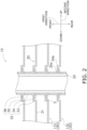
- the plurality of fins 30 are disposed in parallel and at equal intervals. Note that, in Fig. 2 , two adjacent fins 30 are illustrated as a first fin 131 and a second fin 132.
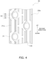
- the fin 30 has a one-surface 30a illustrated in Fig. 3 and a the-other-surface 30b illustrated in Fig. 4 .
- the one-surface 30a is a front surface when viewed from the front in the first direction.
- the the-other-surface 30b is a rear surface when viewed from the rear in the first direction.
- the plurality of fins 30 each include a body portion 31 and collar portions 32.
- the body portion 31 extends in the second direction that intersects the first direction.
- the body portion 31 extends in the vertical direction that is the second direction orthogonal to the first direction.
- the vertical direction is the gravity direction.
- the body portion 31 is a flat plate-shaped member.
- the body portion 31 is formed with notches 31a for enhancing heat transfer.
- a plurality of notches 31a are arranged in a third direction orthogonal to the first direction.
- the third direction is the left-right direction.
- the notches 31a extend in the second direction.
- the notches 31a protrude frontward.
- the notch 31a protrudes from the one-surface 30a of the fin 30 toward the the-other-surface 30b of an adjacent fin 30.
- the collar portion 32 allows the heat transfer tube 20 to pass therethrough.
- the collar portion 32 has a through hole for allowing the heat transfer tube 20 to pass therethrough.
- the collar portion 32 has a first portion 33, a second portion 34, a third portion 35, and a fourth portion 36.
- the first portion 33, the second portion 34, the third portion 35, and the fourth portion 36 are formed of one member.
- the first portion 33, the second portion 34, the third portion 35, and the fourth portion 36 are formed by nesting.
- the first portion 33 extends from the body portion 31 in the first direction.
- the first portion 33 is orthogonal to the body portion 31.
- the second portion 34 extends from the first portion 33 toward the heat transfer tube 20. In other words, the second portion 34 extends in the second direction.
- the second portion 34 is orthogonal to the first portion 33. The second portion will be described later.
- the third portion 35 extends in the first direction from the second portion 34 along the heat transfer tube 20.
- the third portion 35 is in contact with the heat transfer tube 20.
- the third portion 35 is orthogonal to the second portion 34.
- the fourth portion 36 extends radially outward from the third portion 35. In other words, the fourth portion 36 extends in the second direction.
- the fourth portion 36 is orthogonal to the third portion 35.
- the second portion 34 of the first fin 131 is in contact with a distal end portion of the collar portion 32 of the second fin 132 disposed adjacent to the first fin 131.
- the second portion 34 of the first fin is in contact with the fourth portion 36 of the second fin disposed adjacent to the first fin.
- the second portion 34 and the fourth portion 36 extend in the same direction.
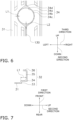
- the second portion 34 will be described. As illustrated in Figs. 5 and 6 , the second portion 34 has, when viewed from the first direction (from the front in Figs. 5 and 6 ) (in front view), a portion where a distance between an inner peripheral surface 34a and an outer peripheral surface 34b is a first dimension L1, and a portion where the distance between the inner peripheral surface 34a and the outer peripheral surface 34b is a second dimension L2. As illustrated in Figs. 6 to 8 , the second dimension L2 is greater than the first dimension L1.
- the first dimension L1 is a dimension of the portion extending along the third direction orthogonal to the first direction. Specifically, the portion having the first dimension L1 is positioned at at least a left end portion and a right end portion.
- the portion having the first dimension L1 is a portion of the second portion 34 where triangular portions 34d, described later, are not disposed.
- the second dimension L2 is a dimension of the portion extending along the second direction. Specifically, the portion having the second dimension L2 is positioned at at least one of an upper end portion and a lower end portion. Here, the portion having the second dimension L2 is the upper end portion and is the lower end portion, of the second portion 34.
- the second portion 34 has a drop shape when viewed from the first direction (from the front in Figs. 5 and 6 ).
- the second portion 34 has, when viewed from the first direction (from the front in Figs. 5 and 6 ), an annular portion 34c having an annular shape and the triangular portions 34d each having a triangular shape.
- the triangular portion 34d is continuous with a part of the annular portion 34c.
- the triangular portion 34d has a V shape.
- the annular portion 34c is a region surrounded by two concentric circles.
- the annular portion 34c is positioned on the entire perimeter of the second portion 34.
- the portion having the first dimension L1 is formed solely by the annular portion 34c not including the triangular portions 34d. Therefore, in the present embodiment, the first dimension L1 has a constant value.
- the portion having the second dimension L2 is formed of the triangular portion 34d and the annular portion 34c. Therefore, in the present embodiment, the second dimension L2 does not have a constant value. Specifically, the second dimension L2 has a value greater than the first dimension L1 of the annular portion 34c, and the value varies depending on the position. A maximum value of the second dimension L2 is, for example, not less than twice the first dimension L1. Here, the maximum value of the second dimension L2 is a distance extending downward (toward the inner peripheral surface 34a) from an upper end of the second portion 34 and also a distance extending upward (toward the inner peripheral surface 34a) from a lower end of the second portion 34.
- the triangular portion 34d is disposed at the lower end portion of the second portion 34. Specifically, the triangular portion 34d has a shape extending downward. Here, the triangular portion 34d is also disposed at the upper end portion of the second portion 34. Specifically, the triangular portion 34d also has a shape extending upward.
- first dimension L1 is, for example, 0.5 mm or more and 0.9 mm or less.
- the second dimension L2 is, for example, 1.0 mm or more and 1.9 mm or less.
- the maximum value of the second dimension L2 is, for example, 1.5 mm or more and 1.9 mm or less.
- the fin 30 is provided with drain ribs 130.
- the drain rib 130 extends from a convex space S formed by the first portion 33 and the second portion 34 of the first fin 131 and a distal end of the collar portion 32 of the second fin 132 illustrated in Fig. 2 .
- the drain rib 130 causes water in the convex space S to flow in the second direction (here, downward).
- the convex space S is formed by the first portion 33 and the second portion 34 of the first fin 131 and the fourth portion 36 of the second fin 132. Specifically, the distal end (the fourth portion 36 in Fig. 2 ) of the collar portion 32 of the second fin 132 enters a concave portion around the collar portion 32 of the first fin 131 disposed adjacent to the second fin 132, so that the convex space S is formed within the concave portion.
- the convex space S has a drop shape when viewed from the first direction (here, from the front).
- the convex space S includes, when viewed from the first direction, an annular space and triangular spaces.
- the annular space is provided on the entire perimeter.
- the triangular spaces are continuous with the annular space.
- the triangular space is provided at the upper end portion and the lower end portion.
- the convex space S formed by the first portion 33 of the first fin 131, the portion having the first dimension L1 of the second portion 34 of the first fin 131, and the fourth portion 36 of the second fin 132 is, for example, 0.1 mm or more and 0.3 mm or less.
- the convex space S formed by the first portion 33 of the first fin 131, the portion having the second dimension L2 of the second portion 34 of the first fin 131, and the fourth portion 36 of the second fin 132 is, for example, 0.4 mm or more and 1.4 mm or less.
- the convex space S formed by the first portion 33 of the first fin 131, the portion (the upper end portion or the lower end portion) having the maximum value of the second dimension L2 of the second portion 34 of the first fin 131, and the fourth portion 36 of the second fin 132 is, for example, 1.1 mm or more and 1.4 mm or less.
- the drain rib 130 are provided on the body portion 31. As illustrated in Figs. 3 , 4 , 9 , and 10 , the drain rib 130 protrudes in the first direction. Here, the drain rib 130 protrudes frontward. Specifically, the drain rib 130 protrudes from the one-surface 30a of the fin 30 toward the the-other-surface 30b of an adjacent fin 30. In the present embodiment, as illustrated in Figs. 9 and 10 , the drain rib 130 protrudes in the first direction to the second portion 34. In other words, the height of the drain rib 130 in the first direction is the same as the height of the second portion 34. Further, in other words, the position of the drain rib 130 in the first direction is the same as the position of the second portion 34 in the first direction.
- the drain rib 130 has a ridge shape when viewed from a one-surface 30a (front surface) side as illustrated in Figs. 3 and 10 , and has a groove shape when viewed from a the-other-surface 30b (rear surface) side as illustrated in Figs. 4 and 10 .
- the drain rib 130 has a V shape when viewed from below.
- the drain rib 130 extends in the second direction.
- the drain rib 130 extends in the vertical direction, and here, extends in the gravity direction.
- the drain rib 130 extends in the second direction from a first collar portion 32 to a collar portion 32 disposed below the first collar portion 32.
- the drain rib 130 extends from the lower end of the second portion of the upper first collar portion 32 to the upper end of the second portion 34 of the lower second collar portion 32.
- the drain rib 130 is connected to the portion having the second dimension L2 of the second portion 34. Specifically, the drain rib 130 is connected to the triangular portion 34d of the second portion 34. More specifically, the drain rib 130 is connected to a pointed portion of the triangular portion 34d of the second portion 34. The drain rib 130 extends from the triangular space within the convex space S.
- a refrigerant is sent to the heat transfer tubes 20 of the heat exchanger 10 that serves as the indoor heat exchanger 231 in the refrigerant circuit 210. Then, the refrigerant that flows inside the through holes of the heat transfer tubes 20 exchanges heat with indoor air that flows outside the heat transfer tubes 20.
- condensation water hereinafter, also referred to as water
- This water tends to accumulate in the convex space S formed by the first portion 33 and the second portion 34 of the first fin 131 and the fourth portion 36 that is the distal end portion of the collar portion 32 of the second fin 132.
- the second portion 34 of the fin 30 has, when viewed in the first direction, the portion where the distance between the inner peripheral surface 34a and the outer peripheral surface 34b is the first dimension L1, and the portion where the distance between the inner peripheral surface 34a and the outer peripheral surface 34b is the second dimension L2 greater than the first dimension L1.
- This structure can guide water accumulated in the space defined by the portion having the first dimension L1 of the first fin 131 and the fourth portion 36 of the second fin 132 to the space defined by the portion having the second dimension L2 of the first fin 131 and the fourth portion 36 of the second fin 132.
- the fin 30 includes the drain ribs 130.
- the drain rib 130 extends from the convex space S formed by the first portion 33 and the second portion 34 of the first fin 131 and the fourth portion 36 that is the distal end of the collar portion 32 of the second fin 132. Since the drain rib 130 extends from the convex space S, water accumulated in the convex space S can be guided to the drain rib 130. The drain rib 130 drains water.
- the inventor of the present invention has found a problem unique to the heat exchanger 10 that includes the collar portion 32 having the first portion 33, the second portion 34, and the third portion 35, with the second portion 34 of the first fin 131 being in contact with the distal end portion of the collar portion 32 of the second fin 132 disposed adjacent to the first fin 131.
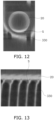
- the inventor of the present invention has found a problem that, as illustrated in Figs. 12 and 13 , in a conventional fin 330 that does not have a portion having the second dimension L2, water tends to accumulate in the convex space S formed by the first portion 33 and the second portion 34 of the first fin 131 and the distal end portion of the collar portion 32 of the second fin 132.
- the heat exchanger 10 of the present embodiment has been conceived as a result of intensive studies.
- the heat exchanger 10 includes the heat transfer tube 20 and the plurality of fins 30.
- the heat transfer tube 20 extends in the first direction.
- the plurality of fins 30 are stacked in the first direction.
- the plurality of fins 30 each include the body portion 31 and the collar portion 32.
- the body portion 31 extends in the second direction that intersects the first direction.
- the collar portion 32 allows the heat transfer tube 20 to pass therethrough.
- the collar portion 32 has the first portion 33, the second portion 34, and the third portion 35.
- the first portion 33 extends from the body portion 31 in the first direction.
- the second portion 34 extends from the first portion 33 toward the heat transfer tube 20.
- the third portion 35 extends in the first direction from the second portion 34 along the heat transfer tube 20.
- the second portion 34 of the first fin 131 is in contact with the distal end portion of the collar portion 32 of the second fin 132 disposed adjacent to the first fin 131.
- the second portion 34 has, when viewed from the first direction, a portion where the distance between the inner peripheral surface 34a and the outer peripheral surface 34b is the first dimension L1, and a portion where the distance between the inner peripheral surface 34a and the outer peripheral surface 34b is the second dimension L2.
- the second dimension L2 is greater than the first dimension L1.
- water accumulated in the space defined by the portion having the first dimension L1 of the first fin 131 and the distal end portion of the collar portion 32 of the second fin 132 can be drained via the space defined by the portion having the second dimension L2 of the first fin 131 and the distal end portion of the collar portion 32 of the second fin 132. Therefore, drainage of water from the convex space S where water tends to accumulate can be facilitated.
- the collar portion 32 further has the fourth portion 36.
- the fourth portion 36 extends radially outward from the third portion 35.
- the second portion 34 of the first fin 131 is in contact with the fourth portion 36 of the second fin 132 disposed adjacent to the first fin 131.
- the fourth portion 36 allows the plurality of fins 30, 131, 132 to be easily stacked in the first direction.
- the second dimension L2 is a portion extending along the second direction.
- the portion having the second dimension L2 is positioned in a direction in which the body portion 31 extends. Therefore, a structure that causes water in the convex space S to flow toward the space defined by the portion having the second dimension L2 of the first fin 131 and the distal end portion of the collar portion 32 of the second fin 132 can be easily achieved.
- the second portion 34 has, when viewed from the first direction, the annular portion 34c and the triangular portion 34d.
- the annular portion 34c has an annular shape.
- the triangular portion 34d is continuous with a part of the annular portion 34c and has a triangular shape.
- the triangular portion 34d configures the portion having the second dimension L2.
- the triangular portion 34d is disposed at the lower end portion of the second portion 34.
- the triangular portion 34d is disposed at the upper end portion and the lower end portion of the second portion 34.
- the portion having the second dimension L2 is positioned at the upper end portion, water from above can easily flow to the left and right in the annular portion 34c. This water flows from the left and right in the annular portion 34c to the triangular portion 34d positioned at the lower end portion. Therefore, the water in the convex space S can be smoothly discharged downward.
- the fin 30 is provided with the drain rib 130.
- the drain rib 130 extends from the convex space S formed by the first portion 33 and the second portion 34 of the first fin 131 and the distal end of the collar portion 32 of the second fin 132.
- a structure where the drain rib 130 discharges water from the convex space S can be achieved.
- the drain rib 130 is continuous with the portion having the second dimension L2.
- the fin 30 has a structure that guides water from the portion having the second dimension L2 to the drain rib 130.
- This structure can easily guide water in the convex space S to the drain rib 130.
- the drain rib 130 is provided on the body portion 31.
- the drain rib 130 protrudes in the first direction to the second portion 34.
- This structure can easily guide water in the convex space S to the drain rib 130.
- the fin 30 includes a plurality of collar portions 32.
- the drain rib 130 extends in the second direction from the first collar portion 32 to the collar portion 32 disposed below the first collar portion 32.
- water in the convex space S defined by the collar portions 32 on the upper stage can be guided to the convex space S defined by the collar portions 32 on the lower stage through the drain rib 130.
- the heat exchanger 10 of the present embodiment is included in the indoor unit 230 of the air-conditioning apparatus 200. In this manner, the heat exchanger 10 of the present embodiment is suitably used as the indoor heat exchanger 231 disposed indoors.
- the portion having the second dimension L2 (in Figs. 3 to 6 , the triangular portion 34d) is disposed at both end portions in the second direction, but the present invention is not limited thereto.
- the portion having the second dimension L2 is disposed only at the lower end portion.
- the triangular portion 34d is not disposed at the upper end portion, but is disposed only at the lower end portion.
- the triangular space within the convex space S is, when viewed from the first direction, provided at both end portions in the second direction, but the present invention is not limited thereto.
- the triangular space within the convex space S is provided only at the lower end portion.
- the annular space is provided at the upper end portion of the convex space S.
- the triangular portion 34d has a V shape when viewed from the first direction, but the present invention is not limited thereto.
- the triangular portion 34d of the present modification has a U shape.
- the drain rib 130 has a V shape when viewed from below, but the present invention is not limited thereto.
- the drain rib 130 of the present modification has a U shape when viewed from below.
- water is drained from the drain rib 130 via the space defined by the portion having the second dimension L2 of the first fin 131 and the fourth portion of the second fin 132, but the drainage mechanism is not limited thereto.
- the collar portion 32 has the first portion 33, the second portion 34, the third portion 35, and the fourth portion 36, but the fourth portion 36 may be omitted.
- the fin 30 is formed with the notches 31a for enhancing heat transfer, but the shape, number, arrangement, and the like of the notches 31a are not limited.
- the notch 31a may extend in a direction that intersects the second direction.
- the notch 31a may protrude rearward.
- the heat exchanger 10 is applied to the indoor heat exchanger 231, but the present invention is not limited thereto. In the present modification, the heat exchanger 10 is applied to the outdoor heat exchanger 223.
- the heat exchanger 10 is applied to the air-conditioning apparatus 200, but the present invention is not limited thereto.
- the heat exchanger 10 may be applied to a hot water supply apparatus, a floor heating apparatus, and a refrigeration apparatus such as a refrigerating device.
Landscapes
- Engineering & Computer Science (AREA)
- Physics & Mathematics (AREA)
- Mechanical Engineering (AREA)
- Thermal Sciences (AREA)
- General Engineering & Computer Science (AREA)
- Geometry (AREA)
- Heat-Exchange Devices With Radiators And Conduit Assemblies (AREA)
Abstract
Description
- The present disclosure relates to a heat exchanger.
- Conventionally, as disclosed in PTL 1 (
Japanese Unexamined Patent Application Publication No. 2015-123458 collar portion 10 inFig. 1 of PTL 1 includes a dish-shaped seat portion 11, a vertical cylindrical portion 12 disposed above the seat portion 11, and a flare portion 13 disposed above the vertical cylindrical portion 12. - The inventor of the present invention has found a problem that, when fins 1 illustrated in
Fig. 1 of PTL 1 are stacked, in connection with thecollar portion 10, the flare portion 13 of one fin 1 enters a concave portion of the vertical cylindrical portion 12 of another fin 1 that is disposed adjacent to the fin 1, and water tends to accumulate in a convex space formed within that concave portion. - A heat exchanger of a first aspect includes a heat transfer tube and a plurality of fins. The heat transfer tube extends in a first direction. The plurality of fins are stacked in the first direction. The plurality of fins each include a body portion and a collar portion. The body portion extends in a second direction that intersects the first direction. The collar portion allows the heat transfer tube to pass therethrough. The collar portion has a first portion, a second portion, and a third portion. The first portion extends from the body portion in the first direction. The second portion extends from the first portion toward the heat transfer tube. The third portion extends in the first direction from the second portion along the heat transfer tube. The second portion of a first fin is in contact with a distal end portion of the collar portion of a second fin disposed adjacent to the first fin. The second portion has, when viewed from the first direction: a portion where a distance between an inner peripheral surface and an outer peripheral surface is a first dimension; and a portion where the distance between the inner peripheral surface and the outer peripheral surface is a second dimension. The second dimension is greater than the first dimension.
- In the heat exchanger of the first aspect, water tends to accumulate in a convex space formed by the first portion and the second portion of the first fin and the distal end portion of the collar portion of the second fin. However, according to the heat exchanger of the first aspect, water accumulated in the space defined by the portion having the first dimension of the first fin and the distal end portion of the collar portion of the second fin can be drained via the space defined by the portion having the second dimension of the first fin and the distal end portion of the collar portion of the second fin. Therefore, drainage of water from the space where water tends to accumulate can be facilitated.
- A heat exchanger of a second aspect is the heat exchanger of the first aspect, in which the collar portion further has a fourth portion. The fourth portion extends radially outward from the third portion. The second portion of the first fin is in contact with the fourth portion of the second fin disposed adjacent to the first fin.
- In the heat exchanger of the second aspect, the fourth portion allows the plurality of fins to be easily stacked in the first direction.
- In addition, in the heat exchanger of the second aspect, the problem that water tends to accumulate in the convex space formed by the fourth portion of the second fin and the first portion and the second portion of the first fin is significant, so the effect of including the second portion is significant.
- A heat exchanger of a third aspect is the heat exchanger of the first or the second aspect, in which the second dimension is a portion extending along the second direction.
- In the heat exchanger of the third aspect, the portion having the second dimension is positioned in a direction in which the body portion extends. Therefore, a structure that causes water in the convex space to flow toward the space defined by the portion having the second dimension of the first fin and the distal end portion of the collar portion of the second fin can be easily achieved.
- A heat exchanger of a fourth aspect is the heat exchanger of any one of the first to third aspects, in which the second portion has, when viewed from the first direction, an annular portion and a triangular portion. The annular portion has an annular shape. The triangular portion is continuous with a part of the annular portion and has a triangular shape. The triangular portion configures in the portion having the second dimension.
- In the heat exchanger of the fourth aspect, a structure that causes water in the space defined by the annular portion of the first fin and the distal end portion of the collar portion of the second fin to flow toward the triangular portion can be easily achieved.
- A heat exchanger of a fifth aspect is the heat exchanger of the fourth aspect, in which the triangular portion is disposed at a lower end portion of the second portion.
- In the heat exchanger of the fifth aspect, since the portion having the second dimension is positioned at the lower end portion, water in the convex space can be discharged downward.
- A heat exchanger of a sixth aspect is the heat exchanger of any one of the first to fifth aspects, in which, the fins are each provided with a drain rib. The drain rib extends from the convex space formed by the first portion and the second portion of the first fin and a distal end of the collar portion of the second fin.
- In the heat exchanger of the sixth aspect, a structure where the drain rib discharges water in the convex space can be achieved.
- A heat exchanger of a seventh aspect is the heat exchanger of the sixth aspect, in which the drain rib is connected to the portion having the second dimension.
- In the heat exchanger of the seventh aspect, water accumulated in the space defined by the portion having the first dimension of the first fin and the distal end portion of the collar portion of the second fin can be drained from the drain rib via the space defined by the portion having the second dimension of the first fin and the distal end portion of the collar portion of the second fin.
- A heat exchanger of an eighth aspect is the heat exchanger of the sixth or the seventh aspect, in which the drain rib is provided on the body portion. The drain rib protrudes in the first direction to the second portion.
- In the heat exchanger of the eighth aspect, water in the convex space can be easily guided to the drain rib.
- A heat exchanger of a ninth aspect is the heat exchanger of any one of the sixth to eighth aspects, in which the fin includes a plurality of collar portions. The drain rib extends in the second direction from a first collar portion to a collar portion disposed below the first collar portion.
- In the heat exchanger of the ninth aspect, water in the convex space defined by the collar portions on the upper stage can be guided to the convex space defined by the collar portions on the lower stage through the drain rib.
- A heat exchanger of a tenth aspect is the heat exchanger of any one of the first to ninth aspects, in which the heat exchanger is included in an indoor unit of an air-conditioning apparatus.
- The heat exchanger of the tenth aspect can be applied to the heat exchanger of the indoor unit of the air-conditioning apparatus.
-
- [
Fig. 1] Fig. 1 is a schematic configuration diagram of an air-conditioning apparatus including a heat exchanger according to an embodiment of the present disclosure. - [
Fig. 2] Fig. 2 is a cross-sectional view of the heat exchanger according to an embodiment of the present disclosure. - [
Fig. 3] Fig. 3 is a perspective view of a fin included in the heat exchanger when viewed from the front. - [
Fig. 4] Fig.4 is a plan view of the fin included in the heat exchanger when viewed from the rear. - [
Fig. 5] Fig. 5 is a plan view of the vicinity of one collar portion of the heat exchanger when viewed from the front. - [
Fig. 6] Fig. 6 is a view obtained by omitting a third portion and a fourth portion fromFig. 5 and hatching a second portion inFig. 5 . - [
Fig. 7] Fig. 7 is a cross-sectional view taken along line VII-VII inFig. 5 . - [
Fig. 8] Fig. 8 is a cross-sectional view taken along line VIII-VIII inFig. 5 . - [
Fig. 9] Fig. 9 is a cross-sectional view taken along line IX-IX inFig. 5 . - [
Fig. 10] Fig. 10 is a bottom view of the fin included in the heat exchanger when viewed from below. - [
Fig. 11] Fig. 11 is a view illustrating a flow of water inFig. 4 . - [
Fig. 12] Fig. 12 is a photograph of the vicinity of a conventional collar portion when viewed from the front. - [
Fig. 13] Fig. 13 is a photograph of the vicinity of a plurality of conventional collar portions when viewed from the right. - [
Fig. 14] Fig. 14 is a plan view of the vicinity of one collar portion of a heat exchanger of a modification when viewed from the front. - An air-conditioning apparatus including a heat exchanger according to an embodiment of the present disclosure will be described with reference to
Fig. 1 . As illustrated inFig. 1 , an air-conditioning apparatus 200 is an apparatus used for cooling and heating the inside of a room in a building or the like by performing a vapor compression refrigeration cycle operation. - The air-
conditioning apparatus 200 mainly includes anoutdoor unit 220, anindoor unit 230, and a liquid-refrigerant connection pipe 240 and a gas-refrigerant connection pipe 250 that connect theoutdoor unit 220 and theindoor unit 230 to each other. In addition, a vaporcompression refrigerant circuit 210 of the air-conditioning apparatus 200 is configured by connecting theoutdoor unit 220 and theindoor unit 230 via the liquid-refrigerant connection pipe 240 and the gas-refrigerant connection pipe 250. - The
outdoor unit 220 is installed outdoors. Theoutdoor unit 220 mainly includes acompressor 221, a flowpath switching mechanism 222, anoutdoor heat exchanger 223, and anexpansion mechanism 224. - The
compressor 221 is a mechanism that compresses a low-pressure refrigerant in a refrigeration cycle until the pressure of the refrigerant becomes high. - The flow
path switching mechanism 222 is a mechanism that switches the flow direction of a refrigerant when switching between a cooling operation and a heating operation. During the cooling operation, the flowpath switching mechanism 222 connects a discharge side of thecompressor 221 into contact with a gas side of theoutdoor heat exchanger 223, and connects a gas side of an indoor heat exchanger 231 (described later) and a suction side of thecompressor 221 to each other via the gas-refrigerant connection pipe 250 (see solid lines in the flowpath switching mechanism 222 inFig. 1 ). On the other hand, during the heating operation, the flowpath switching mechanism 222 connects the discharge side of thecompressor 221 and the gas side of theindoor heat exchanger 231 to each other via the gas-refrigerant connection pipe 250, and connects the gas side of theoutdoor heat exchanger 223 and the suction side of thecompressor 221 to each other (see broken lines in the flowpath switching mechanism 222 inFig. 1 ). - The
outdoor heat exchanger 223 is a heat exchanger that functions as a radiator for a refrigerant during the cooling operation, and functions as an evaporator for the refrigerant during the heating operation. Theoutdoor heat exchanger 223 has a liquid side connected to theexpansion mechanism 224, and has the gas side connected to the flowpath switching mechanism 222. - The
expansion mechanism 224 is a mechanism that decompresses a high pressure liquid refrigerant that has radiated heat in theoutdoor heat exchanger 223 before the refrigerant is sent to theindoor heat exchanger 231 during the cooling operation, and decompresses a high pressure liquid refrigerant that has radiated heat in theindoor heat exchanger 231 before the refrigerant is sent to theoutdoor heat exchanger 223 during the heating operation. - In addition, the
outdoor unit 220 is provided with anoutdoor fan 225 for sucking outdoor air into theoutdoor unit 220, supplying the outdoor air to theoutdoor heat exchanger 223, and then discharging the outdoor air to the outside of theoutdoor unit 220. - The
indoor unit 230 is installed indoors. Theindoor unit 230 mainly includes theindoor heat exchanger 231 and anindoor fan 232. - The
indoor heat exchanger 231 is a heat exchanger that functions as an evaporator for a refrigerant during the cooling operation, and functions as a radiator for the refrigerant during the heating operation. Theindoor heat exchanger 231 has a liquid side connected to the liquid-refrigerant connection pipe 240, and has the gas side connected to the gas-refrigerant connection pipe 250. - In addition, the
indoor unit 230 is provided with theindoor fan 232 for sucking indoor air into theindoor unit 230, supplying the indoor air to theindoor heat exchanger 231, and then discharging the indoor air to the outside of theindoor unit 230. - In a case where the air-
conditioning apparatus 200 performs the cooling operation, a low-pressure refrigerant in the refrigeration cycle is sucked into thecompressor 221, is compressed until the pressure of the refrigerant becomes high in the refrigeration cycle, and is then discharged. The high-pressure refrigerant discharged from thecompressor 221 is sent to theoutdoor heat exchanger 223 through the flowpath switching mechanism 222. The high-pressure refrigerant sent to theoutdoor heat exchanger 223 exchanges heat with outdoor air supplied by theoutdoor fan 225 and radiates heat in theoutdoor heat exchanger 223. The high-pressure refrigerant that has radiated heat in theoutdoor heat exchanger 223 is sent to theexpansion mechanism 224, and is decompressed until the pressure of the refrigerant becomes low in the refrigeration cycle. The low-pressure refrigerant decompressed in theexpansion mechanism 224 is sent to theindoor heat exchanger 231 through the liquid-refrigerant connection pipe 240. The low-pressure refrigerant sent to theindoor heat exchanger 231 exchanges heat with indoor air supplied by theindoor fan 232 and evaporates in theindoor heat exchanger 231. As a result, the indoor air is cooled and blown out into the room. The low-pressure refrigerant that has evaporated in theindoor heat exchanger 231 is sucked again into thecompressor 221 through the gas-refrigerant connection pipe 250 and the flowpath switching mechanism 222. - In a case where the air-
conditioning apparatus 200 performs the heating operation, a low-pressure refrigerant in the refrigeration cycle is sucked into thecompressor 221, is compressed until the pressure of the refrigerant becomes high in the refrigeration cycle, and is then discharged. The high-pressure refrigerant discharged from thecompressor 221 is sent to theindoor heat exchanger 231 through the flowpath switching mechanism 222 and the gas-refrigerant connection pipe 250. The high-pressure refrigerant sent to theindoor heat exchanger 231 exchanges heat with indoor air supplied by theindoor fan 232 and radiates heat in theindoor heat exchanger 231. As a result, the indoor air is heated and blown out into the room. The high-pressure refrigerant that has radiated heat in theindoor heat exchanger 231 is sent to theexpansion mechanism 224 through the liquid-refrigerant connection pipe 240, and is decompressed until the pressure of the refrigerant becomes low in the refrigeration cycle. The low-pressure refrigerant decompressed in theexpansion mechanism 224 is sent to theoutdoor heat exchanger 223. The low-pressure refrigerant sent to theoutdoor heat exchanger 223 exchanges heat with outdoor air supplied by theindoor fan 232 and evaporates in theoutdoor heat exchanger 223. The low-pressure refrigerant that has evaporated in theoutdoor heat exchanger 223 is sucked again into thecompressor 221 through the flowpath switching mechanism 222. - A
heat exchanger 10 according to an embodiment of the present disclosure will be described with reference toFigs. 1 to 11 . Note that, in the following description, expressions indicating directions, such as "up", "down", "left", "right", "front", and "rear" are used as appropriate. These expressions indicate the respective directions in which theheat exchanger 10 is in an ordinary state of use, and are not intended to be limiting. - The
heat exchanger 10 of the present embodiment is included in theindoor unit 230 of the air-conditioning apparatus 200 inFig. 1 . Specifically, theheat exchanger 10 is theindoor heat exchanger 231 illustrated inFig. 1 . Theheat exchanger 10 of the present embodiment is a cross-fin tube heat exchanger. - As illustrated in
Fig. 2 , theheat exchanger 10 includes aheat transfer tube 20 and a plurality offins 30. Theheat transfer tube 20 extends in a first direction. Thefins 30 are stacked in the first direction. Here, the first direction is the front-rear direction. Theheat exchanger 10 causes heat exchange between a refrigerant that flows inside theheat transfer tube 20 and air that flows outside theheat transfer tube 20. Theheat exchanger 10 causes heat exchange between air and the refrigerant without mixing the air and the refrigerant with each other. - The
heat exchanger 10 of the present embodiment includes a plurality ofheat transfer tubes 20. The plurality ofheat transfer tubes 20 are arranged in a second direction. The second direction intersects the first direction. Here, the second direction is orthogonal to the first direction. Specifically, the second direction is the vertical direction. - The
heat transfer tube 20 allows a refrigerant to flow therethrough. Theheat transfer tube 20 has a cylindrical shape. Here, theheat transfer tube 20 is a round tube. - The
heat transfer tube 20 is formed with a through hole allowing the refrigerant that exchanges heat with indoor air in theheat exchanger 10 to pass therethrough. The through hole extends through theheat transfer tube 20 along the first direction. Here, the first direction is the longitudinal direction of theheat transfer tube 20. Theheat transfer tube 20 is made of, for example, aluminum or an aluminum alloy. (2-2-2) Fin - The
fins 30 increase the heat transfer area between theheat transfer tubes 20 and indoor air, and enhance heat exchange between the refrigerant and the indoor air. Thefin 30 is in contact with theheat transfer tubes 20. Thefin 30 is made of, for example, aluminum or an aluminum alloy. - The plurality of
fins 30 are arranged in the first direction. Thefins 30 are disposed so as to intersect (here, orthogonal to) an extending direction of theheat transfer tubes 20. In the present embodiment, the plurality offins 30 are disposed in parallel and at equal intervals. Note that, inFig. 2 , twoadjacent fins 30 are illustrated as afirst fin 131 and asecond fin 132. - The
fin 30 has a one-surface 30a illustrated inFig. 3 and a the-other-surface 30b illustrated inFig. 4 . Here, the one-surface 30a is a front surface when viewed from the front in the first direction. The the-other-surface 30b is a rear surface when viewed from the rear in the first direction. - As illustrated in
Figs. 2 to 10 , the plurality offins 30 each include abody portion 31 andcollar portions 32. Thebody portion 31 extends in the second direction that intersects the first direction. Here, thebody portion 31 extends in the vertical direction that is the second direction orthogonal to the first direction. In the present embodiment, the vertical direction is the gravity direction. Thebody portion 31 is a flat plate-shaped member. - As illustrated in
Figs. 3 and4 , thebody portion 31 is formed withnotches 31a for enhancing heat transfer. A plurality ofnotches 31a are arranged in a third direction orthogonal to the first direction. Here, the third direction is the left-right direction. In addition, thenotches 31a extend in the second direction. Here, thenotches 31a protrude frontward. In other words, thenotch 31a protrudes from the one-surface 30a of thefin 30 toward the the-other-surface 30b of anadjacent fin 30. - As illustrated in
Fig. 2 , thecollar portion 32 allows theheat transfer tube 20 to pass therethrough. Specifically, thecollar portion 32 has a through hole for allowing theheat transfer tube 20 to pass therethrough. - As illustrated in
Figs. 2 to 10 , thecollar portion 32 has afirst portion 33, asecond portion 34, athird portion 35, and afourth portion 36. Thefirst portion 33, thesecond portion 34, thethird portion 35, and thefourth portion 36 are formed of one member. Here, thefirst portion 33, thesecond portion 34, thethird portion 35, and thefourth portion 36 are formed by nesting. - The
first portion 33 extends from thebody portion 31 in the first direction. Here, thefirst portion 33 is orthogonal to thebody portion 31. - The
second portion 34 extends from thefirst portion 33 toward theheat transfer tube 20. In other words, thesecond portion 34 extends in the second direction. Here, thesecond portion 34 is orthogonal to thefirst portion 33. The second portion will be described later. - The
third portion 35 extends in the first direction from thesecond portion 34 along theheat transfer tube 20. Thethird portion 35 is in contact with theheat transfer tube 20. Here, thethird portion 35 is orthogonal to thesecond portion 34. - The
fourth portion 36 extends radially outward from thethird portion 35. In other words, thefourth portion 36 extends in the second direction. Here, thefourth portion 36 is orthogonal to thethird portion 35. - As illustrated in
Fig. 2 , thesecond portion 34 of thefirst fin 131 is in contact with a distal end portion of thecollar portion 32 of thesecond fin 132 disposed adjacent to thefirst fin 131. Here, thesecond portion 34 of the first fin is in contact with thefourth portion 36 of the second fin disposed adjacent to the first fin. Thesecond portion 34 and thefourth portion 36 extend in the same direction. - Here, the
second portion 34 will be described. As illustrated inFigs. 5 and6 , thesecond portion 34 has, when viewed from the first direction (from the front inFigs. 5 and6 ) (in front view), a portion where a distance between an innerperipheral surface 34a and an outerperipheral surface 34b is a first dimension L1, and a portion where the distance between the innerperipheral surface 34a and the outerperipheral surface 34b is a second dimension L2. As illustrated inFigs. 6 to 8 , the second dimension L2 is greater than the first dimension L1. - In
Fig. 6 , the first dimension L1 is a dimension of the portion extending along the third direction orthogonal to the first direction. Specifically, the portion having the first dimension L1 is positioned at at least a left end portion and a right end portion. Here, the portion having the first dimension L1 is a portion of thesecond portion 34 wheretriangular portions 34d, described later, are not disposed. - The second dimension L2 is a dimension of the portion extending along the second direction. Specifically, the portion having the second dimension L2 is positioned at at least one of an upper end portion and a lower end portion. Here, the portion having the second dimension L2 is the upper end portion and is the lower end portion, of the
second portion 34. - In the present embodiment, the
second portion 34 has a drop shape when viewed from the first direction (from the front inFigs. 5 and6 ). In other words, thesecond portion 34 has, when viewed from the first direction (from the front inFigs. 5 and6 ), anannular portion 34c having an annular shape and thetriangular portions 34d each having a triangular shape. Thetriangular portion 34d is continuous with a part of theannular portion 34c. InFigs. 5 and6 , thetriangular portion 34d has a V shape. - The
annular portion 34c is a region surrounded by two concentric circles. Theannular portion 34c is positioned on the entire perimeter of thesecond portion 34. The portion having the first dimension L1 is formed solely by theannular portion 34c not including thetriangular portions 34d. Therefore, in the present embodiment, the first dimension L1 has a constant value. - The portion having the second dimension L2 is formed of the
triangular portion 34d and theannular portion 34c. Therefore, in the present embodiment, the second dimension L2 does not have a constant value. Specifically, the second dimension L2 has a value greater than the first dimension L1 of theannular portion 34c, and the value varies depending on the position. A maximum value of the second dimension L2 is, for example, not less than twice the first dimension L1. Here, the maximum value of the second dimension L2 is a distance extending downward (toward the innerperipheral surface 34a) from an upper end of thesecond portion 34 and also a distance extending upward (toward the innerperipheral surface 34a) from a lower end of thesecond portion 34. - The
triangular portion 34d is disposed at the lower end portion of thesecond portion 34. Specifically, thetriangular portion 34d has a shape extending downward. Here, thetriangular portion 34d is also disposed at the upper end portion of thesecond portion 34. Specifically, thetriangular portion 34d also has a shape extending upward. - Note that the first dimension L1 is, for example, 0.5 mm or more and 0.9 mm or less. The second dimension L2 is, for example, 1.0 mm or more and 1.9 mm or less. The maximum value of the second dimension L2 is, for example, 1.5 mm or more and 1.9 mm or less.
- As illustrated in
Figs. 3 to 6 ,9 , and10 , thefin 30 is provided withdrain ribs 130. Thedrain rib 130 extends from a convex space S formed by thefirst portion 33 and thesecond portion 34 of thefirst fin 131 and a distal end of thecollar portion 32 of thesecond fin 132 illustrated inFig. 2 . Thedrain rib 130 causes water in the convex space S to flow in the second direction (here, downward). - In the present embodiment, the convex space S is formed by the
first portion 33 and thesecond portion 34 of thefirst fin 131 and thefourth portion 36 of thesecond fin 132. Specifically, the distal end (thefourth portion 36 inFig. 2 ) of thecollar portion 32 of thesecond fin 132 enters a concave portion around thecollar portion 32 of thefirst fin 131 disposed adjacent to thesecond fin 132, so that the convex space S is formed within the concave portion. - Specifically, the convex space S has a drop shape when viewed from the first direction (here, from the front). In other words, the convex space S includes, when viewed from the first direction, an annular space and triangular spaces. The annular space is provided on the entire perimeter. The triangular spaces are continuous with the annular space. In the present embodiment, the triangular space is provided at the upper end portion and the lower end portion.
- Note that the convex space S formed by the
first portion 33 of thefirst fin 131, the portion having the first dimension L1 of thesecond portion 34 of thefirst fin 131, and thefourth portion 36 of thesecond fin 132 is, for example, 0.1 mm or more and 0.3 mm or less. The convex space S formed by thefirst portion 33 of thefirst fin 131, the portion having the second dimension L2 of thesecond portion 34 of thefirst fin 131, and thefourth portion 36 of thesecond fin 132 is, for example, 0.4 mm or more and 1.4 mm or less. The convex space S formed by thefirst portion 33 of thefirst fin 131, the portion (the upper end portion or the lower end portion) having the maximum value of the second dimension L2 of thesecond portion 34 of thefirst fin 131, and thefourth portion 36 of thesecond fin 132 is, for example, 1.1 mm or more and 1.4 mm or less. - As illustrated in
Figs. 3 ,4 , and9 , thedrain rib 130 are provided on thebody portion 31. As illustrated inFigs. 3 ,4 ,9 , and10 , thedrain rib 130 protrudes in the first direction. Here, thedrain rib 130 protrudes frontward. Specifically, thedrain rib 130 protrudes from the one-surface 30a of thefin 30 toward the the-other-surface 30b of anadjacent fin 30. In the present embodiment, as illustrated inFigs. 9 and10 , thedrain rib 130 protrudes in the first direction to thesecond portion 34. In other words, the height of thedrain rib 130 in the first direction is the same as the height of thesecond portion 34. Further, in other words, the position of thedrain rib 130 in the first direction is the same as the position of thesecond portion 34 in the first direction. - Specifically, the
drain rib 130 has a ridge shape when viewed from a one-surface 30a (front surface) side as illustrated inFigs. 3 and10 , and has a groove shape when viewed from a the-other-surface 30b (rear surface) side as illustrated inFigs. 4 and10 . In the present embodiment, thedrain rib 130 has a V shape when viewed from below. - As illustrated in
Figs. 3 and4 , thedrain rib 130 extends in the second direction. In the present embodiment, thedrain rib 130 extends in the vertical direction, and here, extends in the gravity direction. - Specifically, the
drain rib 130 extends in the second direction from afirst collar portion 32 to acollar portion 32 disposed below thefirst collar portion 32. Here, between thefirst collar portion 32 and asecond collar portion 32 that are disposed adjacent to each other in the vertical direction, thedrain rib 130 extends from the lower end of the second portion of the upperfirst collar portion 32 to the upper end of thesecond portion 34 of the lowersecond collar portion 32. - The
drain rib 130 is connected to the portion having the second dimension L2 of thesecond portion 34. Specifically, thedrain rib 130 is connected to thetriangular portion 34d of thesecond portion 34. More specifically, thedrain rib 130 is connected to a pointed portion of thetriangular portion 34d of thesecond portion 34. Thedrain rib 130 extends from the triangular space within the convex space S. - During the operation such as the cooling operation and the heating operation of the air-
conditioning apparatus 200 illustrated inFig. 1 , a refrigerant is sent to theheat transfer tubes 20 of theheat exchanger 10 that serves as theindoor heat exchanger 231 in therefrigerant circuit 210. Then, the refrigerant that flows inside the through holes of theheat transfer tubes 20 exchanges heat with indoor air that flows outside theheat transfer tubes 20. During this operation, condensation water (hereinafter, also referred to as water) may be generated on thefins 30. This water tends to accumulate in the convex space S formed by thefirst portion 33 and thesecond portion 34 of thefirst fin 131 and thefourth portion 36 that is the distal end portion of thecollar portion 32 of thesecond fin 132. - However, in the present embodiment, the
second portion 34 of thefin 30 has, when viewed in the first direction, the portion where the distance between the innerperipheral surface 34a and the outerperipheral surface 34b is the first dimension L1, and the portion where the distance between the innerperipheral surface 34a and the outerperipheral surface 34b is the second dimension L2 greater than the first dimension L1. This structure can guide water accumulated in the space defined by the portion having the first dimension L1 of thefirst fin 131 and thefourth portion 36 of thesecond fin 132 to the space defined by the portion having the second dimension L2 of thefirst fin 131 and thefourth portion 36 of thesecond fin 132. - In addition, in the present embodiment, the
fin 30 includes thedrain ribs 130. Thedrain rib 130 extends from the convex space S formed by thefirst portion 33 and thesecond portion 34 of thefirst fin 131 and thefourth portion 36 that is the distal end of thecollar portion 32 of thesecond fin 132. Since thedrain rib 130 extends from the convex space S, water accumulated in the convex space S can be guided to thedrain rib 130. Thedrain rib 130 drains water. - Specifically, as illustrated in
Fig. 11 , water accumulated in the annular space within the convex space S is guided to the triangular space disposed below the annular space. The annular space is defined by the portion having the first dimension L1 of thefirst fin 131 and thefourth portion 36 of thesecond fin 132, while the triangular space is defined by the portion having the second dimension L2 of thefirst fin 131 and thefourth portion 36 of thesecond fin 132. Since thedrain rib 130 is connected to the portion having the second dimension L2, water guided to the triangular space formed by the portion having the second dimension L2 is further guided to thedrain rib 130. As a result, water flows along the groove, formed on the the-other-surface 30b side, of thedrain rib 130 and flows to thecollar portion 32 disposed below thedrain rib 130. In this manner, condensation water attached on thefin 30 flows downward. - The inventor of the present invention has found a problem unique to the
heat exchanger 10 that includes thecollar portion 32 having thefirst portion 33, thesecond portion 34, and thethird portion 35, with thesecond portion 34 of thefirst fin 131 being in contact with the distal end portion of thecollar portion 32 of thesecond fin 132 disposed adjacent to thefirst fin 131. Specifically, the inventor of the present invention has found a problem that, as illustrated inFigs. 12 and 13 , in aconventional fin 330 that does not have a portion having the second dimension L2, water tends to accumulate in the convex space S formed by thefirst portion 33 and thesecond portion 34 of thefirst fin 131 and the distal end portion of thecollar portion 32 of thesecond fin 132. In order to solve this problem, theheat exchanger 10 of the present embodiment has been conceived as a result of intensive studies. - The
heat exchanger 10 according to the present embodiment includes theheat transfer tube 20 and the plurality offins 30. Theheat transfer tube 20 extends in the first direction. The plurality offins 30 are stacked in the first direction. The plurality offins 30 each include thebody portion 31 and thecollar portion 32. Thebody portion 31 extends in the second direction that intersects the first direction. Thecollar portion 32 allows theheat transfer tube 20 to pass therethrough. Thecollar portion 32 has thefirst portion 33, thesecond portion 34, and thethird portion 35. Thefirst portion 33 extends from thebody portion 31 in the first direction. Thesecond portion 34 extends from thefirst portion 33 toward theheat transfer tube 20. Thethird portion 35 extends in the first direction from thesecond portion 34 along theheat transfer tube 20. Thesecond portion 34 of thefirst fin 131 is in contact with the distal end portion of thecollar portion 32 of thesecond fin 132 disposed adjacent to thefirst fin 131. Thesecond portion 34 has, when viewed from the first direction, a portion where the distance between the innerperipheral surface 34a and the outerperipheral surface 34b is the first dimension L1, and a portion where the distance between the innerperipheral surface 34a and the outerperipheral surface 34b is the second dimension L2. The second dimension L2 is greater than the first dimension L1. - According to the
heat exchanger 10 of the present embodiment, water accumulated in the space defined by the portion having the first dimension L1 of thefirst fin 131 and the distal end portion of thecollar portion 32 of thesecond fin 132 can be drained via the space defined by the portion having the second dimension L2 of thefirst fin 131 and the distal end portion of thecollar portion 32 of thesecond fin 132. Therefore, drainage of water from the convex space S where water tends to accumulate can be facilitated. - In this manner, water accumulation on the
fin 30 can be suppressed, and drainage performance can be improved, thereby enabling a reduction in the duration for which theheat exchanger 10 remains in a wet state. Therefore, corrosion of theheat transfer tube 20 and thefins 30 can be suppressed. In addition, the generation of mold in theheat exchanger 10 can be suppressed, thereby enabling a reduction in odor issues. - In the
heat exchanger 10 of the present embodiment, thecollar portion 32 further has thefourth portion 36. Thefourth portion 36 extends radially outward from thethird portion 35. Thesecond portion 34 of thefirst fin 131 is in contact with thefourth portion 36 of thesecond fin 132 disposed adjacent to thefirst fin 131. - Here, the
fourth portion 36 allows the plurality offins - In addition, the problem that water tends to accumulate in the convex space S formed by the
fourth portion 36 of thesecond fin 132 and thefirst portion 33 and thesecond portion 34 of thefirst fin 131 is pronounced, so the effect of including thesecond portion 34 in the present embodiment is significant. - In the
heat exchanger 10 of the present embodiment, the second dimension L2 is a portion extending along the second direction. - Here, the portion having the second dimension L2 is positioned in a direction in which the
body portion 31 extends. Therefore, a structure that causes water in the convex space S to flow toward the space defined by the portion having the second dimension L2 of thefirst fin 131 and the distal end portion of thecollar portion 32 of thesecond fin 132 can be easily achieved. - In the
heat exchanger 10 of the present embodiment, thesecond portion 34 has, when viewed from the first direction, theannular portion 34c and thetriangular portion 34d. Theannular portion 34c has an annular shape. Thetriangular portion 34d is continuous with a part of theannular portion 34c and has a triangular shape. Thetriangular portion 34d configures the portion having the second dimension L2. - Here, a structure that causes water in the space defined by the
annular portion 34c of thefirst fin 131 and the distal end portion of thecollar portion 32 of thesecond fin 132 to flow toward thetriangular portion 34d can be easily achieved. - In the
heat exchanger 10 of the present embodiment, thetriangular portion 34d is disposed at the lower end portion of thesecond portion 34. - Here, since the portion having the second dimension L2 is positioned at the lower end portion, water in the convex space S can be discharged downward.
- In the
heat exchanger 10 of the present embodiment, thetriangular portion 34d is disposed at the upper end portion and the lower end portion of thesecond portion 34. - Here, since the portion having the second dimension L2 is positioned at the upper end portion, water from above can easily flow to the left and right in the
annular portion 34c. This water flows from the left and right in theannular portion 34c to thetriangular portion 34d positioned at the lower end portion. Therefore, the water in the convex space S can be smoothly discharged downward. - In the
heat exchanger 10 of the present embodiment, thefin 30 is provided with thedrain rib 130. Thedrain rib 130 extends from the convex space S formed by thefirst portion 33 and thesecond portion 34 of thefirst fin 131 and the distal end of thecollar portion 32 of thesecond fin 132. - In the
heat exchanger 10 of the present embodiment, a structure where thedrain rib 130 discharges water from the convex space S can be achieved. - In the
heat exchanger 10 of the present embodiment, thedrain rib 130 is continuous with the portion having the second dimension L2. - In this manner, the
fin 30 has a structure that guides water from the portion having the second dimension L2 to thedrain rib 130. This structure can easily guide water in the convex space S to thedrain rib 130. - In the
heat exchanger 10 of the present embodiment, thedrain rib 130 is provided on thebody portion 31. Thedrain rib 130 protrudes in the first direction to thesecond portion 34. - This structure can easily guide water in the convex space S to the
drain rib 130. - In the
heat exchanger 10 of the present embodiment, thefin 30 includes a plurality ofcollar portions 32. Thedrain rib 130 extends in the second direction from thefirst collar portion 32 to thecollar portion 32 disposed below thefirst collar portion 32. - Here, water in the convex space S defined by the
collar portions 32 on the upper stage can be guided to the convex space S defined by thecollar portions 32 on the lower stage through thedrain rib 130. - In the
heat exchanger 10 of the present embodiment, theheat exchanger 10 is included in theindoor unit 230 of the air-conditioning apparatus 200. In this manner, theheat exchanger 10 of the present embodiment is suitably used as theindoor heat exchanger 231 disposed indoors. - In the above-described embodiment, the portion having the second dimension L2 (in
Figs. 3 to 6 , thetriangular portion 34d) is disposed at both end portions in the second direction, but the present invention is not limited thereto. In the present modification, as illustrated inFig. 14 , the portion having the second dimension L2 is disposed only at the lower end portion. In other words, thetriangular portion 34d is not disposed at the upper end portion, but is disposed only at the lower end portion. - In the above-described embodiment, the triangular space within the convex space S is, when viewed from the first direction, provided at both end portions in the second direction, but the present invention is not limited thereto. In the present modification, the triangular space within the convex space S is provided only at the lower end portion. In other words, the annular space is provided at the upper end portion of the convex space S.
- In the above-described embodiment, the
triangular portion 34d has a V shape when viewed from the first direction, but the present invention is not limited thereto. Thetriangular portion 34d of the present modification has a U shape. - In the above-described embodiment, the
drain rib 130 has a V shape when viewed from below, but the present invention is not limited thereto. Thedrain rib 130 of the present modification has a U shape when viewed from below. - In the above-described embodiment, water is drained from the
drain rib 130 via the space defined by the portion having the second dimension L2 of thefirst fin 131 and the fourth portion of thesecond fin 132, but the drainage mechanism is not limited thereto. - In the above-described embodiment, the
collar portion 32 has thefirst portion 33, thesecond portion 34, thethird portion 35, and thefourth portion 36, but thefourth portion 36 may be omitted. - In the above-described embodiment, the
fin 30 is formed with thenotches 31a for enhancing heat transfer, but the shape, number, arrangement, and the like of thenotches 31a are not limited. Thenotch 31a may extend in a direction that intersects the second direction. In addition, thenotch 31a may protrude rearward. - In the above-described embodiment, the
heat exchanger 10 is applied to theindoor heat exchanger 231, but the present invention is not limited thereto. In the present modification, theheat exchanger 10 is applied to theoutdoor heat exchanger 223. - In the above-described embodiment, the
heat exchanger 10 is applied to the air-conditioning apparatus 200, but the present invention is not limited thereto. Theheat exchanger 10 may be applied to a hot water supply apparatus, a floor heating apparatus, and a refrigeration apparatus such as a refrigerating device. - The embodiment of the present disclosure has been described heretofore, and it will be understood that a variety of modifications in mode and detail may be made without departing from the gist and scope of the present disclosure as set forth in claims.
-
- 10
- HEAT EXCHANGER
- 20
- HEAT TRANSFER TUBE
- 30,131,132
- FIN
- 31
- BODY PORTION
- 32
- COLLAR PORTION
- 33
- FIRST PORTION
- 34
- SECOND PORTION
- 34a
- INNER PERIPHERAL SURFACE
- 34b
- OUTER PERIPHERAL SURFACE
- 34c
- ANNULAR PORTION
- 34d
- TRIANGULAR PORTION
- 35
- THIRD PORTION
- 36
- FOURTH PORTION
- 130
- DRAIN RIB
- 200
- AIR-CONDITIONING APPARATUS
- 230
- INDOOR UNIT
- PTL 1:
Japanese Unexamined Patent Application Publication No. 2015-123458
Claims (10)
- A heat exchanger (10) comprising:a heat transfer tube (20) extending in a first direction; anda plurality of fins (30, 131, 132) stacked in the first direction, whereinthe plurality of the fins each include:a body portion (31) extending in a second direction that intersects the first direction; anda collar portion (32) that allows the heat transfer tube to pass therethrough,the collar portion has:a first portion (33) extending from the body portion in the first direction;a second portion (34) extending from the first portion toward the heat transfer tube; anda third portion (35) extending in the first direction from the second portion along the heat transfer tube,the second portion of a first fin (131) in the fins is in contact with a distal end portion of the collar portion of a second fin (131) in the fins disposed adjacent to the first fin, andthe second portion has, when viewed from the first direction:a portion where a distance between an inner peripheral surface (34a) and an outer peripheral surface (34b) is a first dimension (L1); anda portion where the distance between the inner peripheral surface and the outer peripheral surface is a second dimension (L2) greater than the first dimension.
- The heat exchanger according to claim 1, whereinthe collar portion further has a fourth portion (36) extending radially outward from the third portion, andthe second portion of the first fin is in contact with the fourth portion of the second fin disposed adjacent to the first fin.
- The heat exchanger according to claim 1 or 2, wherein the second dimension is a portion extending along the second direction.
- The heat exchanger according to any one of claims 1 to 3, wherein
the second portion has, when viewed from the first direction:an annular portion (34c) having an annular shape; anda triangular portion (34d) that is continuous with a part of the annular portion and has a triangular shape, andthe triangular portion configures in the portion having the second dimension. - The heat exchanger according to claim 4, wherein the triangular portion is disposed at a lower end portion of the second portion.
- The heat exchanger according to any one of claims 1 to 5, whereinthe fins are each provided with a drain rib (130), andthe drain rib extends from a convex space (S) formed by the first portion and the second portion of the first fin and a distal end of the collar portion of the second fin.
- The heat exchanger according to claim 6, wherein the drain rib is connected to the portion having the second dimension.
- The heat exchanger according to claim 6 or 7, whereinthe drain rib is provided on the body portion, andthe drain rib protrudes in the first direction to the second portion.
- The heat exchanger according to any one of claims 6 to 8, whereinthe fin includes a plurality of the collar portions, andthe drain rib extends in the second direction from a first collar portion in the collar portions to a collar portion disposed below the first collar portion.
- The heat exchanger according to any one of claims 1 to 9, wherein the heat exchanger is included in an indoor unit (230) of an air-conditioning apparatus (200).
Applications Claiming Priority (2)
| Application Number | Priority Date | Filing Date | Title |
|---|---|---|---|
| JP2022129116A JP7436895B1 (en) | 2022-08-12 | 2022-08-12 | Heat exchanger |
| PCT/JP2023/028822 WO2024034584A1 (en) | 2022-08-12 | 2023-08-07 | Heat exchanger |
Publications (2)
| Publication Number | Publication Date |
|---|---|
| EP4571232A1 true EP4571232A1 (en) | 2025-06-18 |
| EP4571232A4 EP4571232A4 (en) | 2025-11-26 |
Family
ID=89851847
Family Applications (1)
| Application Number | Title | Priority Date | Filing Date |
|---|---|---|---|
| EP23852546.3A Pending EP4571232A4 (en) | 2022-08-12 | 2023-08-07 | HEAT EXCHANGER |
Country Status (5)
| Country | Link |
|---|---|
| US (1) | US20250180305A1 (en) |
| EP (1) | EP4571232A4 (en) |
| JP (1) | JP7436895B1 (en) |
| CN (1) | CN119654532A (en) |
| WO (1) | WO2024034584A1 (en) |
Family Cites Families (11)
| Publication number | Priority date | Publication date | Assignee | Title |
|---|---|---|---|---|
| JPH0886584A (en) * | 1994-09-20 | 1996-04-02 | Fujitsu General Ltd | Heat exchanger with fins |
| US5722485A (en) * | 1994-11-17 | 1998-03-03 | Lennox Industries Inc. | Louvered fin heat exchanger |
| JPH09119792A (en) * | 1995-10-25 | 1997-05-06 | Hidaka Seiki Kk | Fin for heat exchanger |
| US5752567A (en) * | 1996-12-04 | 1998-05-19 | York International Corporation | Heat exchanger fin structure |
| JP4169079B2 (en) | 2006-10-02 | 2008-10-22 | ダイキン工業株式会社 | Finned tube heat exchanger |
| CN101523148A (en) * | 2006-10-02 | 2009-09-02 | 大金工业株式会社 | Fin tube type heat exchanger |
| JP5304024B2 (en) * | 2008-05-27 | 2013-10-02 | ダイキン工業株式会社 | Finned tube heat exchanger |
| JP6128492B2 (en) | 2012-04-23 | 2017-05-17 | パナソニックIpマネジメント株式会社 | Finned tube heat exchanger and manufacturing method thereof |
| JP5974276B2 (en) * | 2012-04-23 | 2016-08-23 | パナソニックIpマネジメント株式会社 | Finned tube heat exchanger |
| JP5929887B2 (en) | 2013-12-25 | 2016-06-08 | ダイキン工業株式会社 | Heat exchanger fin refurbishing apparatus, heat exchanger fin manufacturing method, and heat exchanger manufacturing method |
| JP2020063883A (en) | 2018-10-18 | 2020-04-23 | 三星電子株式会社Samsung Electronics Co.,Ltd. | Heat exchanger and air conditioner |
-
2022
- 2022-08-12 JP JP2022129116A patent/JP7436895B1/en active Active
-
2023
- 2023-08-07 CN CN202380057938.4A patent/CN119654532A/en active Pending
- 2023-08-07 EP EP23852546.3A patent/EP4571232A4/en active Pending
- 2023-08-07 WO PCT/JP2023/028822 patent/WO2024034584A1/en not_active Ceased
-
2025
- 2025-01-31 US US19/043,262 patent/US20250180305A1/en active Pending
Also Published As
| Publication number | Publication date |
|---|---|
| CN119654532A (en) | 2025-03-18 |
| EP4571232A4 (en) | 2025-11-26 |
| WO2024034584A1 (en) | 2024-02-15 |
| JP7436895B1 (en) | 2024-02-22 |
| JP2024028261A (en) | 2024-03-04 |
| US20250180305A1 (en) | 2025-06-05 |
Similar Documents
| Publication | Publication Date | Title |
|---|---|---|
| EP3232139B1 (en) | Heat exchanger of an air-conditioning device | |
| CN105371539B (en) | Air regulator | |
| US7182127B2 (en) | Heat exchanger | |
| CN206905358U (en) | Heat exchanger and there is its heat exchanger assembly and refrigeration plant | |
| EP4571233A1 (en) | Heat exchanger | |
| CN112113382A (en) | Condenser Improved Refrigerator | |
| CN104969022A (en) | Heat exchanger for air conditioner and air conditioner with heat exchanger | |
| US11802719B2 (en) | Refrigeration cycle apparatus | |
| US20250180305A1 (en) | Heat exchanger | |
| HK1218949A1 (en) | Air conditioning system | |
| US20050126197A1 (en) | Refrigeration apparatus and refrigerator with the refrigeration apparatus | |
| KR100424859B1 (en) | Air conditioner | |
| US5913362A (en) | Condenser having a coolant distributor | |
| KR100822169B1 (en) | Evaporator for Car Air Conditioner | |
| US20200049409A1 (en) | Heat exchanger and refrigeration apparatus | |
| EP4560246A1 (en) | Heat exchanger | |
| CN212921064U (en) | Air conditioner layout structure for automobile and automobile using same | |
| CN101561162A (en) | An air conditioner | |
| US20070240444A1 (en) | Baffle and Method for Enhancing a Defrost Cycle | |
| KR100833850B1 (en) | Ceiling Duct Air Conditioner | |
| JPH10141833A (en) | Electric refrigerator | |
| KR20030000377A (en) | Condenser for air conditioner | |
| KR200239504Y1 (en) | heating exchange equipment of air cooling type condenser in air conditioner | |
| KR102730821B1 (en) | Vehicle cooling module | |
| CN218511023U (en) | Vertical air conditioner |
Legal Events
| Date | Code | Title | Description |
|---|---|---|---|
| STAA | Information on the status of an ep patent application or granted ep patent |
Free format text: STATUS: THE INTERNATIONAL PUBLICATION HAS BEEN MADE |
|
| PUAI | Public reference made under article 153(3) epc to a published international application that has entered the european phase |
Free format text: ORIGINAL CODE: 0009012 |
|
| STAA | Information on the status of an ep patent application or granted ep patent |
Free format text: STATUS: REQUEST FOR EXAMINATION WAS MADE |
|
| 17P | Request for examination filed |
Effective date: 20250219 |
|
| AK | Designated contracting states |
Kind code of ref document: A1 Designated state(s): AL AT BE BG CH CY CZ DE DK EE ES FI FR GB GR HR HU IE IS IT LI LT LU LV MC ME MK MT NL NO PL PT RO RS SE SI SK SM TR |
|
| DAV | Request for validation of the european patent (deleted) | ||
| DAX | Request for extension of the european patent (deleted) | ||
| A4 | Supplementary search report drawn up and despatched |
Effective date: 20251028 |
|
| RIC1 | Information provided on ipc code assigned before grant |
Ipc: F28F 1/32 20060101AFI20251022BHEP Ipc: F25B 39/02 20060101ALI20251022BHEP |