EP4571177A1 - Vehicle sensing and/or lighting unit for a vehicle - Google Patents
Vehicle sensing and/or lighting unit for a vehicle Download PDFInfo
- Publication number
- EP4571177A1 EP4571177A1 EP23217223.9A EP23217223A EP4571177A1 EP 4571177 A1 EP4571177 A1 EP 4571177A1 EP 23217223 A EP23217223 A EP 23217223A EP 4571177 A1 EP4571177 A1 EP 4571177A1
- Authority
- EP
- European Patent Office
- Prior art keywords
- cover lens
- heating wire
- vehicle
- vehicle unit
- connecting section
- Prior art date
- Legal status (The legal status is an assumption and is not a legal conclusion. Google has not performed a legal analysis and makes no representation as to the accuracy of the status listed.)
- Pending
Links
Images

Classifications
-
- F—MECHANICAL ENGINEERING; LIGHTING; HEATING; WEAPONS; BLASTING
- F21—LIGHTING
- F21S—NON-PORTABLE LIGHTING DEVICES; SYSTEMS THEREOF; VEHICLE LIGHTING DEVICES SPECIALLY ADAPTED FOR VEHICLE EXTERIORS
- F21S45/00—Arrangements within vehicle lighting devices specially adapted for vehicle exteriors, for purposes other than emission or distribution of light
- F21S45/60—Heating of lighting devices, e.g. for demisting
-
- F—MECHANICAL ENGINEERING; LIGHTING; HEATING; WEAPONS; BLASTING
- F21—LIGHTING
- F21S—NON-PORTABLE LIGHTING DEVICES; SYSTEMS THEREOF; VEHICLE LIGHTING DEVICES SPECIALLY ADAPTED FOR VEHICLE EXTERIORS
- F21S41/00—Illuminating devices specially adapted for vehicle exteriors, e.g. headlamps
- F21S41/20—Illuminating devices specially adapted for vehicle exteriors, e.g. headlamps characterised by refractors, transparent cover plates, light guides or filters
- F21S41/25—Projection lenses
-
- F—MECHANICAL ENGINEERING; LIGHTING; HEATING; WEAPONS; BLASTING
- F21—LIGHTING
- F21S—NON-PORTABLE LIGHTING DEVICES; SYSTEMS THEREOF; VEHICLE LIGHTING DEVICES SPECIALLY ADAPTED FOR VEHICLE EXTERIORS
- F21S41/00—Illuminating devices specially adapted for vehicle exteriors, e.g. headlamps
- F21S41/20—Illuminating devices specially adapted for vehicle exteriors, e.g. headlamps characterised by refractors, transparent cover plates, light guides or filters
- F21S41/2805—Cover glass
-
- F—MECHANICAL ENGINEERING; LIGHTING; HEATING; WEAPONS; BLASTING
- F21—LIGHTING
- F21S—NON-PORTABLE LIGHTING DEVICES; SYSTEMS THEREOF; VEHICLE LIGHTING DEVICES SPECIALLY ADAPTED FOR VEHICLE EXTERIORS
- F21S45/00—Arrangements within vehicle lighting devices specially adapted for vehicle exteriors, for purposes other than emission or distribution of light
- F21S45/40—Cooling of lighting devices
- F21S45/47—Passive cooling, e.g. using fins, thermal conductive elements or openings
-
- G—PHYSICS
- G01—MEASURING; TESTING
- G01S—RADIO DIRECTION-FINDING; RADIO NAVIGATION; DETERMINING DISTANCE OR VELOCITY BY USE OF RADIO WAVES; LOCATING OR PRESENCE-DETECTING BY USE OF THE REFLECTION OR RERADIATION OF RADIO WAVES; ANALOGOUS ARRANGEMENTS USING OTHER WAVES
- G01S17/00—Systems using the reflection or reradiation of electromagnetic waves other than radio waves, e.g. lidar systems
- G01S17/88—Lidar systems specially adapted for specific applications
- G01S17/93—Lidar systems specially adapted for specific applications for anti-collision purposes
- G01S17/931—Lidar systems specially adapted for specific applications for anti-collision purposes of land vehicles
-
- G—PHYSICS
- G01—MEASURING; TESTING
- G01S—RADIO DIRECTION-FINDING; RADIO NAVIGATION; DETERMINING DISTANCE OR VELOCITY BY USE OF RADIO WAVES; LOCATING OR PRESENCE-DETECTING BY USE OF THE REFLECTION OR RERADIATION OF RADIO WAVES; ANALOGOUS ARRANGEMENTS USING OTHER WAVES
- G01S7/00—Details of systems according to groups G01S13/00, G01S15/00, G01S17/00
- G01S7/48—Details of systems according to groups G01S13/00, G01S15/00, G01S17/00 of systems according to group G01S17/00
- G01S7/481—Constructional features, e.g. arrangements of optical elements
- G01S7/4811—Constructional features, e.g. arrangements of optical elements common to transmitter and receiver
- G01S7/4813—Housing arrangements
-
- H—ELECTRICITY
- H05—ELECTRIC TECHNIQUES NOT OTHERWISE PROVIDED FOR
- H05B—ELECTRIC HEATING; ELECTRIC LIGHT SOURCES NOT OTHERWISE PROVIDED FOR; CIRCUIT ARRANGEMENTS FOR ELECTRIC LIGHT SOURCES, IN GENERAL
- H05B3/00—Ohmic-resistance heating
- H05B3/84—Heating arrangements specially adapted for transparent or reflecting areas, e.g. for demisting or de-icing windows, mirrors or vehicle windshields
- H05B3/86—Heating arrangements specially adapted for transparent or reflecting areas, e.g. for demisting or de-icing windows, mirrors or vehicle windshields the heating conductors being embedded in the transparent or reflecting material
-
- B—PERFORMING OPERATIONS; TRANSPORTING
- B60—VEHICLES IN GENERAL
- B60Q—ARRANGEMENT OF SIGNALLING OR LIGHTING DEVICES, THE MOUNTING OR SUPPORTING THEREOF OR CIRCUITS THEREFOR, FOR VEHICLES IN GENERAL
- B60Q1/00—Arrangement of optical signalling or lighting devices, the mounting or supporting thereof or circuits therefor
- B60Q1/0017—Devices integrating an element dedicated to another function
- B60Q1/0023—Devices integrating an element dedicated to another function the element being a sensor, e.g. distance sensor, camera
-
- F—MECHANICAL ENGINEERING; LIGHTING; HEATING; WEAPONS; BLASTING
- F21—LIGHTING
- F21W—INDEXING SCHEME ASSOCIATED WITH SUBCLASSES F21K, F21L, F21S and F21V, RELATING TO USES OR APPLICATIONS OF LIGHTING DEVICES OR SYSTEMS
- F21W2102/00—Exterior vehicle lighting devices for illuminating purposes
-
- F—MECHANICAL ENGINEERING; LIGHTING; HEATING; WEAPONS; BLASTING
- F21—LIGHTING
- F21W—INDEXING SCHEME ASSOCIATED WITH SUBCLASSES F21K, F21L, F21S and F21V, RELATING TO USES OR APPLICATIONS OF LIGHTING DEVICES OR SYSTEMS
- F21W2107/00—Use or application of lighting devices on or in particular types of vehicles
- F21W2107/10—Use or application of lighting devices on or in particular types of vehicles for land vehicles
Definitions
- the invention relates to a vehicle unit for a vehicle, in particular a vehicle sensing and/or lighting unit, more preferably a vehicle headlamp, wherein the vehicle unit comprises:
- the invention further relates to a vehicle comprising at least one vehicle unit according to the invention.
- Vehicle units with cover lenses including a heating wire are known in the state of the art.
- cover lenses of vehicle units are installed in a vehicle in such a way that one side of the cover lens is in contact with the surrounding air outside of the vehicle.
- a heating wire is embedded in the cover lens to prevent the mentioned freezing.
- the heating wire is operated at a higher power level while driving. This results in areas not exposed to the driving wind not cooling down as drastically, creating a hot spot in these areas on the cover lens.
- This hot spot could, for example, lead to errors in the attachment of the closing plate to the holder. Therefore, it is desired to avoid such a hot spot in the closing plate while operating the heating wire and to enable even heat distribution on the cover plate.
- the cover lens comprises a heat distributing element, which is applied on the heating wire, preferably only on the heating wire, arranged in the connecting section in order to distribute heat in a homogenous way over the connecting section in order to avoid heat hot spots in the heat distribution over the cover lens.
- connection section is not exposed to air outside of the vehicle unit.
- the operable unit is a sensor or a light module, preferably a Radar and/or a Lidar sensor.
- the cover lens is built by over-molding the heating wire and the heat distributing element by plastic material.
- the heating wire and the heat distributing element preferably also a carrier substrate, are embedded within the cover lens.
- the heat distributing element can be to be protected and mechanically stabilized.
- the heat distributing element is arranged on one side of the heating wire or both sides of the heating wire.
- the vehicle headlamp in a correct installed state on a vehicle is exposed to surrounding air of the vehicle.
- the heat distributing element is built as a plate or a foil, preferably a metal plate or a metal foil.
- the heat distributing element is built as a heat sink, which is attached to the heating wire in the connection section.
- the metal is aluminum or copper.
- the vehicle unit comprises a carrier substrate onto which the heating wire is mounted, wherein the heating wire and the carrier substrate are embedded within the cover lens.
- the peripheral rim of the cover lens is the connecting section.
- the heating wire and the carrier substrate are over molded with the at least partially translucent material to form the cover lens, preferably the material is plastic.
- the heat distributing element is embedded within the cover lens.
- the heating wire is coated with an insulated layer at least in the connecting section.
- the insulating layer is built as resin.
- the at least partially translucent material is plastic.
- the connector is arranged on the connecting section of the cover lens.
- connection section is configured for connecting the cover lens onto the holder of the vehicle unit.
- the object of the invention is also achieved by a vehicle comprising at least one vehicle unit according to the invention.
- Fig. 1 shows an example of a vehicle headlamp 10 for a vehicle, wherein the vehicle headlamp 10 comprises a cover lens 100 formed of an at least partially translucent material, which is in this example plastic.
- the cover lens 100 having an operating section 110, for operable units of the vehicle headlamp 10 to engage with an environment outside of the vehicle headlamp 10.
- the vehicle headlamp 10 comprises a light module 600 as an operable unit.
- cover lens having a connecting section 120 for mounting the cover lens 100 onto a holder of the vehicle headlamp 10.
- the vehicle headlamp 10 comprises a holder 200 for holding the cover lens 100, wherein cover lens 100 is mounted on the holder 200 in a way that the connecting section 120 of the cover lens is substantially not visible for an outside observer of the vehicle headlamp 10, as can be seen in Fig. 1 .
- the vehicle headlamp 10 comprises a heating wire 300 and a carrier substrate 310 onto which the heating wire 300 is mounted, wherein the heating wire 300 and the carrier substrate 310 are embedded within the cover lens 100, wherein the heating wire 300 is configured to heat the cover lens 100, wherein the heating wire 300 is arranged in the operating section 110 and the connecting section 120.
- the cover lens 100 is built by over-molding the heating wire 300 and the heat distributing element 500 by plastic material.
- the over-molded parts 150 of the plastic material can be seen for example in Fig. 2 .
- the vehicle headlamp 10 comprises a connector 400 for connecting the heating wire 300 with a power source (not shown in the figures).
- the connector 400 is arranged on the connecting section 120 of the cover lens 100.
- the cover lens 100 comprises a heat distributing element 500, which is applied only on the heating wire 300 arranged in the connecting section 120 in order to distribute heat in a homogenous way over the connecting section 120 in order to avoid heat hot spots in the heat distribution over the cover lens 100.
- the heat distributing element 500 extends to the connector 400, as can be seen in Fig. 1 .
- the heat distributing element 500 is built as a metal foil in the shown example, however, it is possible that the heat distributing element 500 is built as a plate, preferably a metal plate.
- the metal of the metal foil is aluminum or copper.
- the heat distributing element 500 is adhered to the heating wire 300 and also embedded within the cover lens 100.
- the heating wire 300 is coated with an insulated layer 320 in the connecting section 120, as can be seen in Fig. 2 .
- the insulating layer 320 is built as resin.
- the heat distributing element 500 is arranged on both sides of the heating wire 300, meaning that the heat distributing element 500 is arranged in the side where the heating wire 300 is arranged and on the opposite side where the carrier substrate 310 is arranged.
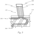
- Fig. 3 shows a further example of a vehicle unit with the same features of the vehicle headlamp 10 of Fig. 1 and Fig. 2 .
- the above to Fig. 1 and Fig. 2 applies to the features with the same reference signs in Fig. 3 .
- Vehicle headlamp 10 Cover lens 100 Operating section 110 Connecting section 120 Over-molded parts 150 Holder 200 Heating wire 300 Carrier substrate 310 Insulated layer 320 Connector 400 Heat distributing element 500 Operable unit 600
Landscapes
- Engineering & Computer Science (AREA)
- General Engineering & Computer Science (AREA)
- Physics & Mathematics (AREA)
- Computer Networks & Wireless Communication (AREA)
- General Physics & Mathematics (AREA)
- Radar, Positioning & Navigation (AREA)
- Remote Sensing (AREA)
- Electromagnetism (AREA)
- Non-Portable Lighting Devices Or Systems Thereof (AREA)
- Arrangement Of Elements, Cooling, Sealing, Or The Like Of Lighting Devices (AREA)
Abstract
Vehicle unit (10) for a vehicle, wherein the vehicle unit (10) comprises:
- a cover lens (100) formed of an at least partially translucent material, wherein the cover lens (100) comprises
- an operating section (110), for operable units (600) of the vehicle unit (10) to engage with an environment outside of the vehicle headlamp (10), for example a light module,
- a connecting section (120) for mounting the cover lens (100) onto a holder of the vehicle unit (10),
- a holder (200) for holding the cover lens (100), wherein cover lens (100) is mounted on the holder (200) in a way that the connecting section (120) of the cover lens is substantially not visible for an outside observer of the vehicle headlamp (10),
- a heating wire (300) embedded within the cover lens (100) and is configured to heat the cover lens (100), wherein the heating wire (300) is arranged in the operating section (110) and the connecting section (120),
- a connector (400) for connecting the heating wire (300) with a power source, wherein the cover lens (100) comprises a heat distributing element (500), which is applied on the heating wire (300), preferably only on the heating wire (300), arranged in the connecting section (120) in order to distribute heat in a homogenous way over the connecting section (120) in order to avoid heat hot spots in the heat distribution over the cover lens (100).
- a cover lens (100) formed of an at least partially translucent material, wherein the cover lens (100) comprises
- an operating section (110), for operable units (600) of the vehicle unit (10) to engage with an environment outside of the vehicle headlamp (10), for example a light module,
- a connecting section (120) for mounting the cover lens (100) onto a holder of the vehicle unit (10),
- a holder (200) for holding the cover lens (100), wherein cover lens (100) is mounted on the holder (200) in a way that the connecting section (120) of the cover lens is substantially not visible for an outside observer of the vehicle headlamp (10),
- a heating wire (300) embedded within the cover lens (100) and is configured to heat the cover lens (100), wherein the heating wire (300) is arranged in the operating section (110) and the connecting section (120),
- a connector (400) for connecting the heating wire (300) with a power source, wherein the cover lens (100) comprises a heat distributing element (500), which is applied on the heating wire (300), preferably only on the heating wire (300), arranged in the connecting section (120) in order to distribute heat in a homogenous way over the connecting section (120) in order to avoid heat hot spots in the heat distribution over the cover lens (100).
Description
- The invention relates to a vehicle unit for a vehicle, in particular a vehicle sensing and/or lighting unit, more preferably a vehicle headlamp, wherein the vehicle unit comprises:
- a cover lens formed of an at least partially translucent material, wherein the cover lens comprises
- an operating section for operable units of the vehicle unit to engage with an environment outside of the vehicle headlamp, for example a light module for illuminating the exterior in front of the vehicle unit,
- a connecting section,
- a holder for holding the cover lens, wherein cover lens is mounted on the holder in a way that the connecting section of the cover lens is substantially not visible for an outside observer of the vehicle headlamp,
- a heating wire embedded within the cover lens and is configured to heat the cover lens, wherein the heating wire is arranged in the operating section and the connecting section,
- a connector for connecting the heating wire with a power source,
- The invention further relates to a vehicle comprising at least one vehicle unit according to the invention.
- Vehicle units with cover lenses including a heating wire are known in the state of the art. Typically cover lenses of vehicle units are installed in a vehicle in such a way that one side of the cover lens is in contact with the surrounding air outside of the vehicle.
- Especially during cold seasons, freezing of water or condensation on the cover lens should be avoided to ensure optimal light output and light distribution of the automotive headlight. For this purpose, a heating wire is embedded in the cover lens to prevent the mentioned freezing. Now, during cold seasons, due to the driving wind, the heating wire is operated at a higher power level while driving. This results in areas not exposed to the driving wind not cooling down as drastically, creating a hot spot in these areas on the cover lens. This hot spot could, for example, lead to errors in the attachment of the closing plate to the holder. Therefore, it is desired to avoid such a hot spot in the closing plate while operating the heating wire and to enable even heat distribution on the cover plate.
- It is an object of the invention to provide an enhanced vehicle units for vehicles.
- To achieve this object the cover lens comprises a heat distributing element, which is applied on the heating wire, preferably only on the heating wire, arranged in the connecting section in order to distribute heat in a homogenous way over the connecting section in order to avoid heat hot spots in the heat distribution over the cover lens.
- In this way, thermal hotspots can be avoided, which potentially destroy a plastic material of the cover lens, since no temperature regulating airflow is in contact with this extending connection section.
- As mentioned in the beginning, the connection section is not exposed to air outside of the vehicle unit.
- Advantageously, the operable unit is a sensor or a light module, preferably a Radar and/or a Lidar sensor.
- Advantageously, the cover lens is built by over-molding the heating wire and the heat distributing element by plastic material. In that way the heating wire and the heat distributing element, preferably also a carrier substrate, are embedded within the cover lens. In that way, the heat distributing element can be to be protected and mechanically stabilized.
- Advantageously, the heat distributing element is arranged on one side of the heating wire or both sides of the heating wire.
- Advantageously, as mentioned above, the vehicle headlamp in a correct installed state on a vehicle is exposed to surrounding air of the vehicle.
- Advantageously, the heat distributing element is built as a plate or a foil, preferably a metal plate or a metal foil.
- Advantageously, the heat distributing element is built as a heat sink, which is attached to the heating wire in the connection section.
- Advantageously, the metal is aluminum or copper.
- Advantageously, the vehicle unit comprises a carrier substrate onto which the heating wire is mounted, wherein the heating wire and the carrier substrate are embedded within the cover lens.
- Advantageously, the peripheral rim of the cover lens is the connecting section.
- Advantageously, the heating wire and the carrier substrate are over molded with the at least partially translucent material to form the cover lens, preferably the material is plastic.
- Advantageously, the heat distributing element is embedded within the cover lens.
- Advantageously, the heating wire is coated with an insulated layer at least in the connecting section.
- Advantageously, the insulating layer is built as resin.
- Advantageously, the at least partially translucent material is plastic.
- Advantageously, the connector is arranged on the connecting section of the cover lens.
- Advantageously, the connection section is configured for connecting the cover lens onto the holder of the vehicle unit.
- The object of the invention is also achieved by a vehicle comprising at least one vehicle unit according to the invention.
- In the following, in order to further demonstrate the present invention, illustrative and non-restrictive embodiments are discussed, as shown in the drawings, which show:
- Fig. 1
- a schematic example of a vehicle headlamp, comprising a cover lens, a holder for the cover lens and a light module as an operable unit,
- Fig. 2
- a cross-section of the cover lens along line A-A in
Fig. 1 , and - Fig. 3
- a further example of a vehicle unit.
-
Fig. 1 shows an example of avehicle headlamp 10 for a vehicle, wherein thevehicle headlamp 10 comprises acover lens 100 formed of an at least partially translucent material, which is in this example plastic. - The
cover lens 100 having anoperating section 110, for operable units of thevehicle headlamp 10 to engage with an environment outside of thevehicle headlamp 10. In the present example thevehicle headlamp 10 comprises alight module 600 as an operable unit. - Further, the cover lens having a connecting
section 120 for mounting thecover lens 100 onto a holder of thevehicle headlamp 10. - The
vehicle headlamp 10 comprises aholder 200 for holding thecover lens 100, whereincover lens 100 is mounted on theholder 200 in a way that the connectingsection 120 of the cover lens is substantially not visible for an outside observer of thevehicle headlamp 10, as can be seen inFig. 1 . - Further, the
vehicle headlamp 10 comprises aheating wire 300 and acarrier substrate 310 onto which theheating wire 300 is mounted, wherein theheating wire 300 and thecarrier substrate 310 are embedded within thecover lens 100, wherein theheating wire 300 is configured to heat thecover lens 100, wherein theheating wire 300 is arranged in theoperating section 110 and the connectingsection 120. - The
cover lens 100 is built by over-molding theheating wire 300 and theheat distributing element 500 by plastic material. The over-moldedparts 150 of the plastic material can be seen for example inFig. 2 . - Further, the
vehicle headlamp 10 comprises aconnector 400 for connecting theheating wire 300 with a power source (not shown in the figures). Theconnector 400 is arranged on the connectingsection 120 of thecover lens 100. - Moreover, the
cover lens 100 comprises aheat distributing element 500, which is applied only on theheating wire 300 arranged in the connectingsection 120 in order to distribute heat in a homogenous way over the connectingsection 120 in order to avoid heat hot spots in the heat distribution over thecover lens 100. Theheat distributing element 500 extends to theconnector 400, as can be seen inFig. 1 . - The
heat distributing element 500 is built as a metal foil in the shown example, however, it is possible that theheat distributing element 500 is built as a plate, preferably a metal plate. The metal of the metal foil is aluminum or copper. Theheat distributing element 500 is adhered to theheating wire 300 and also embedded within thecover lens 100. - Further, the
heating wire 300 is coated with an insulatedlayer 320 in the connectingsection 120, as can be seen inFig. 2 . Theinsulating layer 320 is built as resin. - Further, as can be seen in
Fig. 2 , theheat distributing element 500 is arranged on both sides of theheating wire 300, meaning that theheat distributing element 500 is arranged in the side where theheating wire 300 is arranged and on the opposite side where thecarrier substrate 310 is arranged. -
Fig. 3 shows a further example of a vehicle unit with the same features of thevehicle headlamp 10 ofFig. 1 and Fig. 2 . The above toFig. 1 and Fig. 2 applies to the features with the same reference signs inFig. 3 . -
Vehicle headlamp 10 Cover lens 100 Operating section 110 Connecting section 120 Over-molded parts 150 Holder 200 Heating wire 300 Carrier substrate 310 Insulated layer 320 Connector 400 Heat distributing element 500 Operable unit 600
Claims (13)
- Vehicle unit (10) for a vehicle, in particular a vehicle sensing and/or lighting unit, more preferably a vehicle headlamp, wherein the vehicle unit (10) comprises:- a cover lens (100) formed of an at least partially translucent material, wherein the cover lens (100) comprises- an operating section (110), for operable units (600) of the vehicle unit (10) to engage with an environment outside of the vehicle headlamp (10), for example a light module,- a connecting section (120)- a holder (200) for holding the cover lens (100), wherein cover lens (100) is mounted on the holder (200) in a way that the connecting section (120) of the cover lens is substantially not visible for an outside observer of the vehicle unit (10),- a heating wire (300) embedded within the cover lens (100) and is configured to heat the cover lens (100), wherein the heating wire (300) is arranged in the operating section (110) and the connecting section (120),- a connector (400) for connecting the heating wire (300) with a power source,wherein the connecting section (120) is configured for electronically connecting the heating wire (300) to the connector (400),characterized in thatthe cover lens (100) comprises a heat distributing element (500), which is applied on the heating wire (300), preferably only on the heating wire (300), arranged in the connecting section (120) in order to distribute heat in a homogenous way over the connecting section (120) in order to avoid heat hot spots in the heat distribution over the cover lens (100).
- Vehicle unit according to claim 1, wherein the cover lens (100) is built by over-molding the heating wire (300) and the heat distributing element (500) by plastic material.
- Vehicle unit according to claim 1 or 2, wherein the heat distributing element (500) is arranged on one side of the heating wire (300) or both sides of the heating wire (300).
- Vehicle unit according to any one of the preceding claims, wherein the heat distributing element (500) is built as a plate or a foil, preferably a metal plate or a metal foil.
- Vehicle unit according to claim 4, wherein the metal is aluminum or copper.
- Vehicle unit according to any one of the preceding claims, wherein the vehicle unit (10) comprises a carrier substrate (310) onto which the heating wire (300) is mounted, wherein the heating wire (300) and the carrier substrate (310) are embedded within the cover lens (100).
- Vehicle unit according to any preceding claims, wherein the heat distributing element (500) is embedded within the cover lens (100).
- Vehicle unit according to any one of the preceding claims, wherein the heating wire (300) is coated with an insulated layer (320) at least in the connecting section (120).
- Vehicle unit according to claim 8, wherein the insulating layer is built as resin.
- Vehicle unit according to any one of the preceding claims, wherein the at least partially translucent material is plastic.
- Vehicle unit according to any one of the preceding claims, wherein the connector (400) is arranged on the connecting section (120) of the cover lens (100).
- Vehicle unit according to any one of the preceding claims, wherein the connection section (120) is configured for connecting the cover lens (100) onto the holder of the vehicle unit (10).
- Vehicle comprising at least one vehicle unit according to any one of the preceding claims.
Priority Applications (3)
| Application Number | Priority Date | Filing Date | Title |
|---|---|---|---|
| EP23217223.9A EP4571177A1 (en) | 2023-12-15 | 2023-12-15 | Vehicle sensing and/or lighting unit for a vehicle |
| CN202411826600.3A CN120160096A (en) | 2023-12-15 | 2024-12-12 | Vehicle sensing unit and/or vehicle lighting unit for a vehicle |
| US18/979,160 US12474031B2 (en) | 2023-12-15 | 2024-12-12 | Vehicle sensing and/or lighting unit for a vehicle |
Applications Claiming Priority (1)
| Application Number | Priority Date | Filing Date | Title |
|---|---|---|---|
| EP23217223.9A EP4571177A1 (en) | 2023-12-15 | 2023-12-15 | Vehicle sensing and/or lighting unit for a vehicle |
Publications (1)
| Publication Number | Publication Date |
|---|---|
| EP4571177A1 true EP4571177A1 (en) | 2025-06-18 |
Family
ID=89223905
Family Applications (1)
| Application Number | Title | Priority Date | Filing Date |
|---|---|---|---|
| EP23217223.9A Pending EP4571177A1 (en) | 2023-12-15 | 2023-12-15 | Vehicle sensing and/or lighting unit for a vehicle |
Country Status (3)
| Country | Link |
|---|---|
| US (1) | US12474031B2 (en) |
| EP (1) | EP4571177A1 (en) |
| CN (1) | CN120160096A (en) |
Citations (8)
| Publication number | Priority date | Publication date | Assignee | Title |
|---|---|---|---|---|
| JP2007299676A (en) * | 2006-05-01 | 2007-11-15 | Ichikoh Ind Ltd | Vehicle lighting |
| JP2008103086A (en) * | 2006-10-17 | 2008-05-01 | Koito Mfg Co Ltd | Vehicle lighting |
| JP2010021121A (en) * | 2008-07-14 | 2010-01-28 | Ichikoh Ind Ltd | Vehicular lighting device |
| US20170313235A1 (en) * | 2016-04-29 | 2017-11-02 | Valeo Vision | Automobile headlamp outer lens with overmolded metal electrodes |
| EP2780218B1 (en) * | 2011-11-04 | 2018-04-04 | Truck-Lite Co., LLC | Headlamp assembly with wire heating element for removing water based contamination |
| DE102020124774A1 (en) * | 2020-09-23 | 2022-03-24 | Marelli Automotive Lighting Reutlingen (Germany) GmbH | Projection module of a motor vehicle headlight and motor vehicle headlight with such a projection module |
| KR20230156982A (en) * | 2022-05-09 | 2023-11-16 | 주식회사 나래산업 | The radar cover |
| JP2023169096A (en) * | 2022-05-16 | 2023-11-29 | 株式会社デンソー | film heater |
-
2023
- 2023-12-15 EP EP23217223.9A patent/EP4571177A1/en active Pending
-
2024
- 2024-12-12 US US18/979,160 patent/US12474031B2/en active Active
- 2024-12-12 CN CN202411826600.3A patent/CN120160096A/en active Pending
Patent Citations (8)
| Publication number | Priority date | Publication date | Assignee | Title |
|---|---|---|---|---|
| JP2007299676A (en) * | 2006-05-01 | 2007-11-15 | Ichikoh Ind Ltd | Vehicle lighting |
| JP2008103086A (en) * | 2006-10-17 | 2008-05-01 | Koito Mfg Co Ltd | Vehicle lighting |
| JP2010021121A (en) * | 2008-07-14 | 2010-01-28 | Ichikoh Ind Ltd | Vehicular lighting device |
| EP2780218B1 (en) * | 2011-11-04 | 2018-04-04 | Truck-Lite Co., LLC | Headlamp assembly with wire heating element for removing water based contamination |
| US20170313235A1 (en) * | 2016-04-29 | 2017-11-02 | Valeo Vision | Automobile headlamp outer lens with overmolded metal electrodes |
| DE102020124774A1 (en) * | 2020-09-23 | 2022-03-24 | Marelli Automotive Lighting Reutlingen (Germany) GmbH | Projection module of a motor vehicle headlight and motor vehicle headlight with such a projection module |
| KR20230156982A (en) * | 2022-05-09 | 2023-11-16 | 주식회사 나래산업 | The radar cover |
| JP2023169096A (en) * | 2022-05-16 | 2023-11-29 | 株式会社デンソー | film heater |
Also Published As
| Publication number | Publication date |
|---|---|
| US12474031B2 (en) | 2025-11-18 |
| CN120160096A (en) | 2025-06-17 |
| US20250198592A1 (en) | 2025-06-19 |
Similar Documents
| Publication | Publication Date | Title |
|---|---|---|
| US6773154B2 (en) | Automotive lighting device | |
| EP2148133B1 (en) | Automotive lamp having fan | |
| KR101468829B1 (en) | Arrangement for an image recording device in a vehicle | |
| US10890310B2 (en) | Freezing preventive LED lamp | |
| US20100290241A1 (en) | Vehicular lamp | |
| CN105864703B (en) | Battery charge status indicator for electric vehicles | |
| JP7043001B2 (en) | Millimeter wave radar unit | |
| JP2005063754A (en) | head lamp | |
| US12109950B2 (en) | Attachment device | |
| US20070035957A1 (en) | Light and/or signalling device with light emitting diodes for motor vehicles | |
| CN111156472B (en) | Vehicle lamp | |
| US20150369445A1 (en) | Headlamp and/or tail light assembly, system and method | |
| US20220063371A1 (en) | Modular led headlamp assembly with heating elements for automatically clearing water contamination | |
| JP2022128266A (en) | Vehicular headlight | |
| US11332066B2 (en) | Vehicle body component, method for manufacturing a vehicle body component and method for operating a lighting means arrangement | |
| US12474031B2 (en) | Vehicle sensing and/or lighting unit for a vehicle | |
| JP7484241B2 (en) | Vehicle lighting fixtures | |
| US20070272672A1 (en) | Mirror Glass Component With Integrated Illuminating Means | |
| US20210062991A1 (en) | Light of a vehicle with a cover lens | |
| JP4812697B2 (en) | Snow-prevention device for signal lights and lightning display boards | |
| US12074366B2 (en) | Radome for vehicles | |
| US20070121228A1 (en) | Mirror glass component including an integrated luminescent film | |
| US12345389B2 (en) | Optical device usable as a motor vehicle headlight | |
| WO2023169660A1 (en) | Illumination device for a vehicle | |
| US7905643B2 (en) | Light, especially a rear light for motor vehicles, in addition to a carrier, preferably for said type of light |
Legal Events
| Date | Code | Title | Description |
|---|---|---|---|
| PUAI | Public reference made under article 153(3) epc to a published international application that has entered the european phase |
Free format text: ORIGINAL CODE: 0009012 |
|
| STAA | Information on the status of an ep patent application or granted ep patent |
Free format text: STATUS: THE APPLICATION HAS BEEN PUBLISHED |
|
| AK | Designated contracting states |
Kind code of ref document: A1 Designated state(s): AL AT BE BG CH CY CZ DE DK EE ES FI FR GB GR HR HU IE IS IT LI LT LU LV MC ME MK MT NL NO PL PT RO RS SE SI SK SM TR |
|
| STAA | Information on the status of an ep patent application or granted ep patent |
Free format text: STATUS: REQUEST FOR EXAMINATION WAS MADE |
|
| 17P | Request for examination filed |
Effective date: 20251211 |