EP4571143A1 - Eccentric oscillation type speed reducer - Google Patents
Eccentric oscillation type speed reducer Download PDFInfo
- Publication number
- EP4571143A1 EP4571143A1 EP24214082.0A EP24214082A EP4571143A1 EP 4571143 A1 EP4571143 A1 EP 4571143A1 EP 24214082 A EP24214082 A EP 24214082A EP 4571143 A1 EP4571143 A1 EP 4571143A1
- Authority
- EP
- European Patent Office
- Prior art keywords
- speed reducer
- ring portion
- fixed body
- strain sensor
- type speed
- Prior art date
- Legal status (The legal status is an assumption and is not a legal conclusion. Google has not performed a legal analysis and makes no representation as to the accuracy of the status listed.)
- Pending
Links
Images




Classifications
-
- F—MECHANICAL ENGINEERING; LIGHTING; HEATING; WEAPONS; BLASTING
- F16—ENGINEERING ELEMENTS AND UNITS; GENERAL MEASURES FOR PRODUCING AND MAINTAINING EFFECTIVE FUNCTIONING OF MACHINES OR INSTALLATIONS; THERMAL INSULATION IN GENERAL
- F16H—GEARING
- F16H1/00—Toothed gearings for conveying rotary motion
- F16H1/28—Toothed gearings for conveying rotary motion with gears having orbital motion
- F16H1/32—Toothed gearings for conveying rotary motion with gears having orbital motion in which the central axis of the gearing lies inside the periphery of an orbital gear
-
- F—MECHANICAL ENGINEERING; LIGHTING; HEATING; WEAPONS; BLASTING
- F16—ENGINEERING ELEMENTS AND UNITS; GENERAL MEASURES FOR PRODUCING AND MAINTAINING EFFECTIVE FUNCTIONING OF MACHINES OR INSTALLATIONS; THERMAL INSULATION IN GENERAL
- F16H—GEARING
- F16H57/00—General details of gearing
- F16H57/01—Monitoring wear or stress of gearing elements, e.g. for triggering maintenance
-
- F—MECHANICAL ENGINEERING; LIGHTING; HEATING; WEAPONS; BLASTING
- F16—ENGINEERING ELEMENTS AND UNITS; GENERAL MEASURES FOR PRODUCING AND MAINTAINING EFFECTIVE FUNCTIONING OF MACHINES OR INSTALLATIONS; THERMAL INSULATION IN GENERAL
- F16H—GEARING
- F16H57/00—General details of gearing
- F16H57/08—General details of gearing of gearings with members having orbital motion
-
- F—MECHANICAL ENGINEERING; LIGHTING; HEATING; WEAPONS; BLASTING
- F16—ENGINEERING ELEMENTS AND UNITS; GENERAL MEASURES FOR PRODUCING AND MAINTAINING EFFECTIVE FUNCTIONING OF MACHINES OR INSTALLATIONS; THERMAL INSULATION IN GENERAL
- F16H—GEARING
- F16H1/00—Toothed gearings for conveying rotary motion
- F16H1/28—Toothed gearings for conveying rotary motion with gears having orbital motion
- F16H1/32—Toothed gearings for conveying rotary motion with gears having orbital motion in which the central axis of the gearing lies inside the periphery of an orbital gear
- F16H2001/323—Toothed gearings for conveying rotary motion with gears having orbital motion in which the central axis of the gearing lies inside the periphery of an orbital gear comprising eccentric crankshafts driving or driven by a gearing
Definitions
- the present disclosure relates to an eccentric oscillation type speed reducer.
- Japanese Unexamined Patent Publication No. 2023-99960 discloses an eccentric oscillation type speed reducer that includes an eccentric body, an external gear that is oscillated by the eccentric body, an internal gear that meshes with the external gear, and a carrier that is synchronized with an axial rotation component of the external gear.
- one object of the present disclosure is to provide an eccentric oscillation type speed reducer capable of detecting torque that acts on a constituent member.
- An eccentric oscillation type speed reducer of the present disclosure is an eccentric oscillation type speed reducer including: an eccentric body; an external gear that is oscillated by the eccentric body; an internal gear that meshes with the external gear; and a carrier that is synchronized with an axial rotation component of the external gear, in which one of the internal gear and the carrier configures at least a part of a fixed body that is fixed to an external member, the fixed body includes a first ring portion, a second ring portion that is provided to be separated from the first ring portion in a radial direction and is fixed to the external member, and a distortion generating portion provided between the first ring portion and the second ring portion, and a strain sensor is installed in the distortion generating portion.
- Embodiments for implementing an eccentric oscillation type speed reducer (hereinafter, also referred to as a speed reducer) of the present disclosure will be described. Identical or equivalent elements will be denoted by the same reference numerals and the repeated description thereof will be omitted. In each drawing, for convenience of description, the components are appropriately omitted, enlarged, or reduced. The drawings shall be viewed according to the directions of the symbols.
- a speed reducer 10 includes a crankshaft 14 having at least one eccentric body 12, an external gear 16 capable of being oscillated by the eccentric body 12, an internal gear 18 that meshes with the external gear 16, a synchronous carrier 20 capable of being synchronized with an axial rotation component of the external gear 16, a casing 22 that is disposed outside the external gear 16 in a radial direction, and an asynchronous carrier 24 provided on a side opposite to the synchronous carrier 20 in an axial direction with respect to the external gear 16.
- a center crank type eccentric oscillation type speed reducer 10 will be described.
- the crankshaft 14 is disposed on an oscillation center C16a of the external gear 16.
- the direction along the oscillation center C16a of the external gear 16 will be referred to as an axial direction
- the radial direction and the circumferential direction centered on the oscillation center C16a will be referred to as a radial direction and a circumferential direction.
- the speed reducer 10 includes a fixed body 28 that is fixed to an external member 26, and an output body 32 that outputs rotation to an external driven member 30.
- the external member 26 is provided outside the speed reducer 10 and supports the speed reducer 10.
- the driven member 30 is provided outside the speed reducer 10 and is driven by the output of the output body 32.
- the driven member 30 is, for example, a part of each of various machines such as industrial machines (machine tools, construction machines, or the like), robots (industrial robots, service robots, or the like), and transport equipment (conveyors, vehicles, or the like).
- the output body 32 When rotation is input from a drive source (not shown) to the crankshaft 14, the output body 32 outputs the rotation decelerated more than the rotation of the crankshaft 14 to the driven member 30.
- the drive source is, for example, a motor. However, in addition to the motor, a gear motor, an engine, or the like may be used as the drive source.
- the eccentric body 12 has a circular shape eccentric with respect to a rotation center line C14 of the crankshaft 14.
- the eccentric body 12 can oscillate the external gear 16 by rotating around the rotation center line C14 of the crankshaft 14.
- the term "oscillation” means that a gear center C16b of the external gear 16 rotates around the oscillation center C16a.
- the number of the eccentric bodies 12 is not particularly limited, and one or three or more eccentric bodies 12 may be provided.
- the external gear 16 is individually provided to correspond to each of the plurality of eccentric bodies 12, and is supported by a corresponding eccentric body 12 via an eccentric bearing 34.
- the internal gear 18 includes an internal gear main body 18a and a plurality of inner teeth 18b provided in an inner peripheral portion of the internal gear main body 18a and meshing with the external gear 16.
- the plurality of inner teeth 18b may be integrally provided by the same member as the internal gear main body 18a, or may be configured by a plurality of pins that are rotatably supported by the internal gear main body 18a.
- a pin 36 protrudes in the axial direction from the synchronous carrier 20.
- a plurality of pins 36 are provided at intervals in the circumferential direction.
- the pin 36 may be configured by the same member as the synchronous carrier 20, or may be configured by a member different from the synchronous carrier 20.
- the pin 36 penetrates the external gear 16 in the axial direction, and can receive a load from the external gear 16 when the external gear 16 oscillates.
- the synchronous carrier 20 is "synchronized with the axial rotation component of the external gear 16", means that the axial rotation component of the synchronous carrier 20 is maintained at the same magnitude as the axial rotation component of the external gear 16 within a numerical range including zero.
- the internal gear 18 serves as the output body 32 and the synchronous carrier 20 serves as the fixed body 28, the internal gear 18 rotates during the operation of the speed reducer 10.
- the synchronous carrier 20 is fixed to the external member 26, so that the axial rotation component of the synchronous carrier 20 is maintained at zero.
- the rotation of the external gear 16 is restrained by the synchronous carrier 20 and the pin 36. In this manner, the axial rotation component of the external gear 16 is also maintained at zero.
- the axial rotation component of the synchronous carrier 20 is synchronized with the axial rotation component of the external gear 16.
- the internal gear 18 serves as the fixed body 28 and the synchronous carrier 20 serves as the output body 32
- the external gear 16 rotates during the operation of the speed reducer 10.
- the axial rotation component of the external gear 16 is transmitted to the synchronous carrier 20 via the pin 36.
- the synchronous carrier 20 rotates with the axial rotation component having the same magnitude as the axial rotation component of the external gear 16, and thus is synchronized with the axial rotation component of the external gear 16.
- the asynchronous carrier 24 is not connected to the synchronous carrier 20, and is not synchronized with the axial rotation component of the synchronous carrier 20 during the operation of the speed reducer 10.
- a case where the synchronous carrier 20 serves as the fixed body 28 and the axial rotation component thereof is maintained at zero is considered.
- the asynchronous carrier 24 serves as the output body 32 and rotates, and thus the asynchronous carrier 24 is not synchronized with the axial rotation component of the synchronous carrier 20.
- the asynchronous carrier 20 serves as the output body 32 and rotates is considered.
- the asynchronous carrier 24 serves as the fixed body 28 and maintains the axial rotation component at zero, and thus the asynchronous carrier 24 is not synchronized with the axial rotation component of the synchronous carrier 20.
- the casing 22 of the present embodiment is provided separately from the internal gear 18.
- the casing 22 of the present embodiment is fixed to the synchronous carrier 20 by a fixture such as a bolt (not shown) to be integrated with the synchronous carrier 20.
- the eccentric body 12 of the crankshaft 14 causes the external gear 16 to oscillate.
- the meshing position between the external gears 16 and the internal gear 18 change in the circumferential direction. Accordingly, one (here, the internal gear 18) of the external gear 16 and the internal gear 18 rotates each time the crankshaft 14 rotates once.
- the output body 32 is rotated by the axial rotation component of one of the external gear 16 and the internal gear 18, and outputs rotation to the driven member 30. In this case, the output body 32 outputs the rotation decelerated at a reduction ratio corresponding to a difference in the number of teeth between the external gear 16 and the internal gear 18 with respect to the rotation input to the crankshaft 14 to the driven member 30.
- the speed reducer 10 includes a strain sensor 60 that is installed in a distortion generating portion 44 (to be described later) of the fixed body 28, and a circuit board 62 that is electrically connected to the strain sensor 60.
- the speed reducer 10 has a feature regarding the structure of the fixed body 28.
- the fixed body 28 includes a first ring portion 40, a second ring portion 42 that is provided to be separated from the first ring portion 40 in the radial direction and is fixed to the external member 26, and the distortion generating portion 44 that is provided between the first ring portion 40 and the second ring portion 42.
- the first ring portion 40, the second ring portion 42, and the distortion generating portion 44 of the present embodiment are provided in the synchronous carrier 20. In the present embodiment, these are provided in a single member configuring the synchronous carrier 20.
- the first ring portion 40 has a ring shape.
- the second ring portion 42 has a ring shape.
- the first ring portion 40 of the present embodiment serves as an inner ring portion provided on the inner side in the radial direction, and the second ring portion 42 serves as an outer ring portion provided on the outer side in the radial direction.
- Torque is input to the first ring portion 40 during the operation of the speed reducer 10. Specifically, the torque is transmitted from any one of the external gear 16 and the internal gear 18 during the operation of the speed reducer 10, thereby being input to the first ring portion 40.
- a case where the internal gear 18 is at least a part of the fixed body 28 is considered. In this case, the torque transmitted from the inner teeth 18b of the internal gear 18 is input to the first ring portion 40 of the fixed body 28.
- the second ring portion 42 includes a first fixation portion 46 that is fixed to the external member 26.
- the first fixation portion 46 of the present embodiment is directly fixed to the external member 26 by a fixture 48 such as a bolt.
- a fixture 48 such as a bolt.
- First through-holes 46a for the fixtures 48 are formed in the first fixation portion 46 of the present embodiment at intervals in the circumferential direction.
- the first fixation portion 46 may be fixed to the external member 26 via another constituent member (for example, the casing 22) of the fixed body 28.
- the distortion generating portion 44 connects the first ring portion 40 and the second ring portion 42.
- the distortion generating portion 44 is deformable while transmitting the torque transmitted to the first ring portion 40 to the second ring portion 42.
- the distortion generating portion 44 is configured to be deformable in the circumferential direction more than the first ring portion 40 and the second ring portion 42. It can be said that the amount of deformation of the distortion generating portion 44 in the circumferential direction is larger than those of the first ring portion 40 and the second ring portion 42.
- the distortion generating portion 44 of the present embodiment is configured by a plurality of pillar portions 50 provided at intervals in the circumferential direction.
- a specific example for increasing the amount of deformation of the distortion generating portion 44 in this manner is not particularly limited.
- the distortion generating portion 44 may have a reduced axial dimension with respect to both the first ring portion 40 and the second ring portion 42.
- the distortion generating portion 44 may have a ring shape that is continuous in the circumferential direction.
- the plurality of pillar portions 50 of the present embodiment are provided to extend radially when viewed in the axial direction.
- a specific shape of the pillar portion 50 is not particularly limited.
- the pillar portion 50 may have a linear shape, a curved shape, a crank shape, or the like when viewed in the axial direction.
- the fixed body 28 includes an axial through-hole 52 formed between the pillar portions 50 adjacent to each other.
- the axial through-hole 52 penetrates the fixed body 28 in the axial direction.
- a plurality of axial through-holes 52 are formed at intervals in the circumferential direction.
- the axial through-hole 52 includes a pair of circumferential side portions 52a configured by the pillar portions 50 adjacent to each other, and a pair of radial side portions 52b and 52c configured by the first ring portion 40 and the second ring portion 42.
- the pair of radial side portions 52b and 52c include an inner radial side portion 52b that is configured by an outer peripheral portion of the ring portion 40 located on the inner side in the radial direction, and an outer radial side portion 52c that is configured by an inner peripheral portion of the ring portion 42 located on the outer side in the radial direction.
- the strain sensor 60 is used to detect the torque that acts on the fixed body 28.
- the strain sensor 60 is installed on the axial side surface of the distortion generating portion 44 by adhesion or the like.
- the strain sensor 60 detects an electrical signal corresponding to the strain when the distortion generating portion 44 of the fixed body 28 is deformed.
- the electrical signal detected by the strain sensor 60 indicates the strain of the distortion generating portion 44.
- the strain sensor 60 of the present embodiment detects an electrical signal indicating shear strain of the distortion generating portion 44 in a direction perpendicular to the axial direction.
- the strain sensor 60 of the present embodiment is a strain gauge.
- the strain gauge may be a uniaxial gauge using a single gauge element made of a resistance wire, or a multiaxial gauge such as a rosette gauge using a plurality of gauge elements.
- a biaxial gauge using two gauge elements 64A and 64B is exemplified as the strain gauge.
- the gauge elements 64A and 64B are deformed together with the distortion generating portion 44 of the fixed body 28 to detect an electrical signal indicating a strain in a detection direction corresponding to each of the gauge elements 64A and 64B.
- the gauge elements 64A and 64B of the present embodiment include a first gauge element 64A for detecting the shear strain in a first detection direction D1, and a second gauge element 64B for detecting the shear strain in a second detection direction D2 perpendicular to the first detection direction D1.
- the strain sensor 60 includes a sensor electrode 66 for outputting the detected electrical signal.
- the sensor electrode 66 of the present embodiment is a pad electrode provided on the main surface (axial side surface) of the strain sensor 60. However, a specific example thereof is not particularly limited.
- the sensor electrodes 66 of the present embodiment are individually provided to correspond to each of the gauge elements 64A and 64B, and are provided at both end portions of each of the gauge elements 64A and 64B.
- a plurality of strain sensors 60 are installed at intervals in the circumferential direction. Specifically, in the present embodiment, a total of four strain sensors 60 are installed at intervals in the circumferential direction.
- the strain sensors 60 are wired to configure a bridge circuit (not shown) in accordance with a predetermined wiring method (one-gauge method, two-gauge method, four-gauge method, or the like).
- a wiring method such as the four-gauge method using four strain sensors 60 is exemplified.
- a one-gauge method using one strain sensor 60, a two-gauge method using two strain sensors 60, or the like may be used as the wiring method.
- the number and the disposition position of the strain sensors 60 are not limited thereto, and may be appropriately changed.
- the strain sensor 60 is electrically connected to a processing device 68 for detecting the torque via the circuit board 62.
- the processing device 68 is, for example, a combination of a CPU, a ROM, and a RAM, such as a microcomputer, and is configured by, for example, a processing chip or the like.
- the processing device 68 may be mounted on the circuit board 62, or may be present outside the speed reducer 10.
- the strain sensor 60 outputs an electrical signal indicating the strain of the distortion generating portion 44 to the processing device 68 via the bridge circuit described above.
- the processing device 68 can detect the torque acting on the fixed body 28 by processing the electrical signal output from the strain sensor 60.
- a processing method for detecting torque from an electrical signal of the strain sensor 60 in addition to a known method, a method that can be used in the future may be used and a detailed description thereof will be omitted.
- a circuit element 70 that is used to process the electrical signal of the strain sensor 60 is mounted on the circuit board 62.
- the circuit element 70 is, for example, an amplifier that amplifies the electrical signal of the strain sensor 60, a processing chip that configures the processing device 68, an A/D converter, or the like.
- the circuit element 70 is mounted on a mounting surface 62d provided on the main surface of the circuit board 62.
- the circuit board 62 includes a plurality of substrate electrodes 72 for electrically connecting the circuit board 62 to the strain sensor 60.
- the substrate electrode 72 of the present embodiment is an end surface through-hole electrode provided on an end surface (a tip end surface of a first protrusion portion 62b to be described later) of the circuit board 62.
- the type of the substrate electrode 72 is not particularly limited, and may be a pad electrode provided on the main surface of the circuit board 62.
- the plurality of substrate electrodes 72 configure an electrode group 74 including a plurality of (here, four) substrate electrodes 72.
- the circuit board 62 of the present embodiment includes a plurality of sets of electrode groups 74. The plurality of sets of electrode groups 74 are provided at intervals in the circumferential direction of the circuit board 62.
- the electrode group 74 corresponds to one strain sensor 60, and each of the substrate electrodes 72 belonging to the electrode group 74 is electrically connected to each of the sensor electrodes 66 of a corresponding strain sensor 60.
- the number and positions of the sensor electrodes 66 and the substrate electrodes 72 are not particularly limited.
- the strain sensor 60 and the circuit board 62 are electrically connected to each other via a conductive connection material 76 that is in contact with the strain sensor 60 and the circuit board 62.
- the sensor electrode 66 of the strain sensor 60 and the substrate electrode 72 of the circuit board 62 to be electrically connected to each other are electrically connected to each other via the conductive connection material 76 that is in contact with the sensor electrode 66 and the substrate electrode 72.
- the conductive connection material 76 of the present embodiment is solder, but may be a conductive resin or the like, in addition to solder.
- the circuit board 62 and the strain sensor 60 of the present embodiment are directly connected to each other by the conductive connection material 76, but may be connected to each other by using a wire such as a bonding wire and the conductive connection material 76.
- An electrical signal that is output from the strain sensor 60 sequentially passes through the substrate electrode 72 of the circuit board 62 and a conductor pattern 78 (refer to Fig. 6 ) of the circuit board 62, and is sent to other locations such as the circuit element 70.
- the processing device 68 processes the electrical signal, whereby the torque can be detected.
- the processing device 68 is not essential, and the speed reducer 10 does not need to include the processing device 68.
- the distortion generating portion 44 of the fixed body 28 is configured to be more deformable than each of the ring portions 40 and 42 of the fixed body 28, and is likely to increase the strain when the torque acts.
- the distortion generating portion 44 of the fixed body 28 includes a first recessed portion 80 that accommodates the strain sensor 60.
- the first recessed portion 80 is provided on the axial side surface of the fixed body 28.
- the first recessed portion 80 is provided between the first ring portion 40 and the second ring portion 42, and is recessed in the axial direction with respect to the axial side surface of at least one (here, the first ring portion 40) of the first ring portion 40 and the second ring portion 42.
- the first recessed portion 80 of the present embodiment is also recessed in the axial direction with respect to the axial side surface of a reinforcement portion 90 provided in the distortion generating portion 44 to be described later.
- the strain sensor 60 is installed on a bottom surface portion of the first recessed portion 80 by using adhesion or the like.
- One of the first ring portion 40 and the second ring portion 42 of the fixed body 28 includes a second recessed portion 82 that accommodates at least a part of the circuit board 62.
- the second recessed portion 82 is provided on the axial side surface of the fixed body 28.
- the second recessed portion 82 of the present embodiment is provided on the axial side surface of the second ring portion 42, and is recessed in the axial direction with respect to an axial outer side surface 42a of the second ring portion 42 that is located on the outer side in the axial direction with respect to the second recessed portion 82.
- the circuit board 62 is installed on a bottom surface portion of the second recessed portion 82 by using adhesion or the like.
- An internal space of the second recessed portion 82 of the present embodiment is continuous with an internal space of the first recessed portion 80.
- the bottom surface portion of the second recessed portion 82 and the bottom surface portion of the first recessed portion 80 of the present embodiment are continuous to be flush with each other.
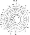
- the second recessed portion 82 includes a circumferential extension portion 82a extending in the circumferential direction when viewed in the axial direction, a first radial extension portion 82b extending in the radial direction from the circumferential extension portion 82a toward the distortion generating portion 44 side, and a second radial extension portion 82c extending in the radial direction from the circumferential extension portion 82a toward the axial through-hole 52 side.
- Fig. 3 the position of each portions is shown by a two-dot chain line.
- the circumferential extension portion 82a is partially shown.
- the circumferential extension portion 82a of the present embodiment extends to be continuous in an annular shape, but may be provided in only a part of the circumferential range.
- the first radial extension portion 82b of the present embodiment is individually provided to correspond to each of the plurality of pillar portions 50.
- a plurality of first radial extension portions 82b are provided at intervals in the radial direction.
- the second radial extension portion 82c of the present embodiment is individually provided to correspond to each of the plurality of axial through-holes 52.
- a plurality of second radial extension portion 82c is provided at intervals in the radial direction.
- the circuit board 62 includes an annular portion 62a facing one of the first ring portion 40 and the second ring portion 42 in the axial direction, the first protrusion portion 62b protruding in the radial direction from the annular portion 62a, and a second protrusion portion 62c protruding in the radial direction from the annular portion 62a.
- a mounting surface 62d of the circuit board 62 is mainly provided in the second protrusion portion 62c in addition to the annular portion 62a of the circuit board 62.
- the annular portion 62a has an annular shape extending in the circumferential direction.
- the annular portion 62a of the present embodiment is continuous in an annular shape, but may be provided in only a part of the circumferential range.
- the annular portion 62a of the present embodiment faces the second ring portion 42 in the axial direction and is installed on the facing second ring portion 42 by using an adhesive or the like.
- the annular portion 62a of the present embodiment faces the second recessed portion 82 of the second ring portion 42 in the axial direction.
- the circuit board 62 is installed on the fixed body 28 in the ring portion 42, which is a location different from the distortion generating portion 44 that is the installation location of the strain sensor 60.
- the annular portion 62a is accommodated in the circumferential extension portion 82a of the second recessed portion 82 of the fixed body 28.
- the first protrusion portion 62b protrudes toward the side of the distortion generating portion 44 of the fixed body 28 in the radial direction with respect to the annular portion 62a.
- the first protrusion portion 62b of the present embodiment protrudes into the first recessed portion 80, in which the distortion generating portion 44 is located, with respect to the annular portion 62a.
- the first protrusion portion 62b is accommodated in the first radial extension portion 82b of the second recessed portion 82 in addition to the first recessed portion 80 of the fixed body 28.
- the substrate electrode 72 is provided at the first protrusion portion 62b.
- the first protrusion portion 62b is connected to the strain sensor 60 by the conductive connection material 76, as described above.
- the second protrusion portion 62c protrudes to the same side as the first protrusion portion 62b in the radial direction with respect to the annular portion 62a.
- the second protrusion portion 62c is provided at a location overlapping the internal space of the axial through-hole 52 of the fixed body 28 when viewed in the axial direction.
- the second protrusion portion 62c protrudes from the annular portion 62a of the circuit board 62 to be located between the pillar portions 50 adjacent to each other when viewed in the axial direction.
- the second protrusion portion 62c protrudes in the radial direction more than the first protrusion portion 62b with respect to the annular portion 62a.
- the second protrusion portion 62c is partially accommodated in the second radial extension portion 82c (refer to Fig. 3 ) of the second recessed portion 82 of the fixed body 28.
- the distortion generating portion 44 includes the first recessed portion 80 that accommodates the strain sensor 60. Therefore, the strain sensor 60 can be made less likely to interfere with other members as compared to a case where the first recessed portion 80 is not provided in the distortion generating portion 44.
- the second ring portion 42 of the fixed body 28 includes the second recessed portion 82 that accommodates the circuit board 62. Therefore, the circuit board 62 can be made less likely to interfere with the other member as compared to a case where the second recessed portion 82 is not provided in the second ring portion 42. This effect can also be obtained in a case where the second recessed portion 82 is provided in the first ring portion 40 instead of the second ring portion 42.
- the circuit board 62 includes the first protrusion portion 62b that protrudes into the first recessed portion 80 of the fixed body 28 and is electrically connected to the strain sensor 60. Therefore, compared to a case where the circuit board 62 does not include the first protrusion portion 62b, the first protrusion portion 62b serving as a part of the circuit board 62 can be present near the strain sensor 60 in the first recessed portion 80. As a result, the circuit board 62 and the strain sensor 60 are easily electrically connected to each other by using the first protrusion portion 62b.
- the circuit board 62 includes the annular portion 62a facing the second ring portion 42 in the axial direction, and the first protrusion portion 62b that protrudes in the radial direction from the annular portion 62a and is connected to the strain sensor 60. Therefore, compared to a case where the circuit board 62 does not include the first protrusion portion 62b, the first protrusion portion 62b serving as a part of the circuit board 62 can be present near the strain sensor 60 installed in the distortion generating portion 44 of the fixed body 28. As a result, the circuit board 62 and the strain sensor 60 are easily connected to each other by using the first protrusion portion 62b. This effect can also be obtained in a case where, instead of the second ring portion 42, the first ring portion 40 faces the annular portion 62a of the circuit board 62 in the axial direction.
- the circuit board 62 includes the second protrusion portion 62c that protrudes to be located between the pillar portions 50, which are adjacent to each other, of the fixed body 28. Therefore, a part of the circuit board 62 can also be present between the pillar portions 50, which are adjacent to each other, of the fixed body 28, and accordingly, it is advantageous to an increase in the area of the mounting surface 62d on which the circuit element 70 is mounted.
- the fixed body 28 includes the reinforcement portion 90 provided at the pillar portion 50.
- the reinforcement portion 90 of the present embodiment is provided to be paired at each of the circumferential side surfaces of the pillar portion 50.
- the reinforcement portion 90 is configured by a protrusion portion that protrudes outward in the axial direction in the pillar portion 50.
- the reinforcement portion 90 is provided to reinforce the pillar portion 50.
- the reinforcement portion 90 of the present embodiment is provided to suppress bending strain of the pillar portion 50 by increasing the stiffness of the pillar portion 50 against bending deformation.
- the terms, bending deformation and bending strain, as referred to herein refer to deformation and strain caused by a moment load acting to tilt the rotation center line of the output body 32.
- the reinforcement portion 90 of the present embodiment includes a radial extension portion 90a provided at a circumferential side portion of the pillar portion 50 and extending in the radial direction.
- the reinforcement portion 90 of the present embodiment includes a circumferential extension portion 90b extending in the circumferential direction from the end portion of the radial extension portion 90a provided at the ring portion 42. The circumferential extension portion 90b extends from the end portion of the radial extension portion 90a toward the outer side in the circumferential direction with respect to the pillar portion 50 in which the reinforcement portion 90 is provided.
- the reinforcement portion 90 of the present embodiment protrudes in the axial direction from the bottom surface portions of the first and second recessed portions 80 and 82.
- the radial extension portion 90a of the reinforcement portion 90 partially forms the first recessed portion 80 and the first radial extension portion 82b of the second recessed portion 82.
- the circumferential extension portion 90b of the reinforcement portion 90 partially forms the circumferential extension portion 82a of the second recessed portion 82.
- the reinforcement portion 90 described above is provided to be paired at each of the pair of the circumferential side portions 52a of the axial through-hole 52.
- the pair of reinforcement portions 90 are interrupted in the outer radial side portion 52c, which is located on the second recessed portion 82 side of the fixed body 28 in the radial direction with respect to the axial through-hole 52, out of the pair of radial side portions 52b and 52c of the axial through-hole 52.
- a location S1 where the pair of reinforcement portions 90 are interrupted is shown by a two-dot chain lines.
- the term "interrupted" as referred to herein means that the pair of reinforcement portions 90 are not continuous in the radial side portion 52c in question when viewed in the axial direction, and are provided at an interval.
- the second radial extension portion 82c that is a part of the second recessed portion 82 is provided at the radial side portion 52c of the axial through-hole 52, which is located at the location S1 where the pair of reinforcement portions 90 are interrupted.
- the second protrusion portion 62c of the circuit board 62 protrudes to be located between the pillar portions 50 adjacent to each other, while passing through the location S1 where the pair of reinforcement portions 90 are interrupted, when viewed in the axial direction.
- the location S1 where the pair of reinforcement portions 90 are interrupted can be used as a disposition space for the circuit board 62 that is accommodated in the second recessed portion 82 of the fixed body 28, and thus it is advantageous to an increase in the area of the mounting surface on which the circuit element 70 is mounted.
- the pillar portion 50 of the fixed body 28 can be reinforced by the pair of reinforcement portions 90 while securing the disposition space for the circuit board 62 in this way.
- a main bearing 92 is disposed between the fixed body 28 and the output body 32.
- the main bearing 92 of the present embodiment is disposed between the casing 22 and the internal gear 18.
- the main bearing 92 may be disposed between the casing 22 and the asynchronous carrier 24.
- the main bearing 92 can transmit the moment load input from the driven member 30 to the output body 32 to the fixed body 28.
- the main bearing 92 of the present embodiment is configured by a cross roller bearing, but may be configured by a four-point contact ball bearing or the like.
- a plurality of main bearings 92 may be provided at intervals in the axial direction.
- the main bearing 92 may be configured by various bearings such as a deep groove ball bearing and an angular ball bearing.
- the fixed body 28 includes the fixation portions 46 and 94 that are fixed to the external member 26.
- the fixation portions 46 and 94 include a second fixation portion 94 that is provided in the casing 22, in addition to the first fixation portion 46 that is provided in the second ring portion 42 of the synchronous carrier 20.
- the first fixation portion 46 of the synchronous carrier 20 and the second fixation portion 94 of the casing 22 of the present embodiment are fixed to the external member 26 by the common fixture 48.
- the second fixation portion 94 of the casing 22 has a second through-hole 94a which is formed at a location overlapping the first through-hole 46a in the axial direction, and through which the fixture 48 passes.
- the speed reducer 10 is provided with a load transmission pathway 96 extending from the output body 32 to the external member 26 via the main bearing 92 and the fixed body 28.
- a part of the load transmission pathway 96 is shown by an arrow.
- the load transmission pathway 96 can transmit the load input from the driven member 30 to the output body 32 to the external member 26.
- the "load” mainly assumes a moment load, but may include an axial load or a radial load.
- the first fixation portion 46 of the second ring portion 42 of the synchronous carrier 20 is provided on the load transmission pathway 96.
- the distortion generating portion 44 of the fixed body 28 is provided at a location different from the load transmission pathway 96.
- the first ring portion 40 of the fixed body 28 is also provided at a location different from the load transmission pathway 96.
- the distortion generating portion 44 is provided at a location different from the load transmission pathway 96 for transmitting a moment load, even though torque is transmitted from the first ring portion 40 during the operation of the speed reducer 10.
- the distortion generating portion 44 of the present embodiment is provided in a part of the synchronous carrier 20 which is integrated with the casing 22, and to which torque is transmitted from the external gear 16 via the pin 36.
- the second ring portion 42 of the synchronous carrier 20 may be directly fixed to the external member 26, as in the present embodiment, or may be fixed to the external member 26 via the casing 22 directly fixed to the external member 26.
- the distortion generating portion 44 of the present embodiment is provided at a position shifted inward in the radial direction with respect to the second ring portion 42 fixed to the external member 26.
- the distortion generating portion 44 of the fixed body 28 is provided at a location different from the load transmission pathway 96 through which the moment load that causes such a decrease in detection accuracy is transmitted. In this way, it is difficult for bending strain to occur in the distortion generating portion 44, which is advantageous to accurate detection of the torque, as described above.
- Fig. 7 is referred to.
- the same contents as those in the first embodiment are applied to components that are not described below, among the components described in the first embodiment.
- the casing 22 and the internal gear 18 are provided separately.
- the speed reducer 10 of the present embodiment is different in that the casing 22 and the internal gear 18 are integrated with each other.
- at least the internal gear main body 18a among the internal gear main body 18a and the plurality of inner teeth 18b configuring the internal gear 18 may be integrated with the casing 22.
- the synchronous carrier 20 and the asynchronous carrier 24 are provided on both sides of the external gear 16 in the axial direction.
- a pair of synchronous carriers 20 are provided on both sides of the external gear 16 in the axial direction.
- the synchronous carriers 20 are connected to each other via the pin 36, and both of the synchronous carriers 20 can be synchronized with the axial rotation component of the external gear 16.
- the fixed body 28 of the embodiment of Fig. 1 is configured by the synchronous carrier 20 and the casing 22, and the output body 32 is configured by the asynchronous carrier 24 and the internal gear 18.
- the fixed body 28 of the present embodiment is configured by the internal gear 18 and the casing 22, and the output body 32 is configured by each of the synchronous carriers 20.
- a pair of main bearings 92 are disposed at an interval in the axial direction between the output body 32 and the fixed body 28.
- Each of the pair of main bearings 92 is disposed between the individual synchronous carrier 20 and the casing 22.
- the first and second ring portions 40 and 42 and the distortion generating portion 44 of the fixed body 28 according to the present embodiment are provided in the casing 22 integrated with the internal gear 18. These are provided in a single member configuring the casing 22, as in the embodiment of Fig. 1 .
- the first ring portion 40 of the fixed body 28 configures an inner ring portion
- the second ring portion 42 configures an outer ring portion.
- a plurality of inner teeth 18b are provided in the inner peripheral portion of the first ring portion 40 of the present embodiment.
- the main bearing 92 is disposed in the inner peripheral portion of the first ring portion 40 of the present embodiment.
- the torque transmitted from the inner teeth 18b of the internal gear 18 is input to the first ring portion 40 of the fixed body 28.
- the distortion generating portion 44 of the fixed body 28 of the present embodiment also includes the first recessed portion 80 that accommodates the strain sensor 60.
- the second ring portion 42 of the fixed body 28 of the present embodiment also includes the second recessed portion 82 that accommodates the circuit board 62.
- the circuit board 62 of the present embodiment also includes the first protrusion portion 62b that protrudes into the first recessed portion 80 of the fixed body 28.
- the speed reducer 10 of the present embodiment includes the components described in (A) to (E) described above, and it is possible to obtain the effects corresponding to the description thereof.
- the speed reducer 10 of the present embodiment has the feature regarding the reinforcement portion 90 of the fixed body 28 of (G), in addition to the second protrusion portion 62c of the circuit board 62 of (F) described above, and it is possible to obtain the effects corresponding to the description thereof.
- the distortion generating portion 44 of the fixed body 28 is provided in the load transmission pathway 96 extending from the output body 32 to the external member 26 via the main bearing 92 and the fixed body 28.
- the moment load is transmitted to the distortion generating portion 44 of the fixed body 28, and thus, a decrease in detection accuracy may be caused in detecting the torque by using the electrical signal of the strain sensor 60 that indicates the shear strain of the distortion generating portion 44.
- various methods including a known method may be adopted to suppress the influence of the bending strain occurred in the distortion generating portion 44.
- a dedicated strain sensor for detecting a bending strain occurred in the fixed body 28 may be installed in the fixed body 28.
- the bending strain component included in the electrical signal of the strain sensor 60 may be reduced by correcting the electrical signal of the strain sensor 60 indicating the shear strain of the distortion generating portion 44, based on the electrical signal of the dedicated strain sensor indicating the bending strain of the distortion generating portion 44.
- the bending strain component included in the electrical signal of the individual strain sensors 60 may be canceled.
- a machine learning model may be used to suppress the influence of the bending strain component included in the electrical signal of the strain sensor 60.
- the machine learning model is trained to output torque in which the influence of a bending strain component included in the electrical signal of the strain sensor 60 is reduced, in a case where the electrical signal of the strain sensor 60 indicating the shear strain of the distortion generating portion 44 is input.
- the machine learning model is, for example, a neural network such as an artificial neuronal network (ANN).
- the entire circuit board 62 of the first embodiment is configured by a rigid substrate.
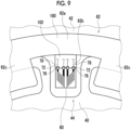
- the annular portion 62a of the circuit board 62 of the present embodiment is configured by a rigid substrate 100
- the first protrusion portion 62b is configured by a flexible substrate 102.
- the flexible substrate 102 is connected to the rigid substrate 100 by various connection methods including a known method.
- the second protrusion portion 62c is configured by the rigid substrate 100 that is common to the annular portion 62a, but may be configured by the flexible substrate 102.
- both the annular portion 62a and the first protrusion portion 62b of the circuit board 62 may be configured by the flexible substrate 102.
- the strain sensor 60 installed in the distortion generating portion 44 and the circuit board 62 installed in the ring portion 42 try to relatively move in the circumferential direction.
- the flexible substrate 102 can be flexibly deformed to follow the relative movement between the circuit board 62 and the strain sensor 60.
- the flexible substrate 102 of the present embodiment is mainly shear-deformable in the circumferential direction, but is also deformable in the axial direction.
- the flexible substrate 102 is provided at a slight interval with respect to the axial side surface of the fixed body 28 to allow flexible deformation of the flexible substrate 102 itself, and is not fixed to the fixed body 28 by an adhesive or the like.
- the annular portion 62a of the circuit board 62 configured by the rigid substrate 100 is fixed to the ring portion 42 of the fixed body 28 by an adhesive or the like.
- the strain sensor 60 and the circuit board 62 try to relatively move in the circumferential direction, the flexible substrate 102 is deformed, so that it is possible to avoid a situation where a local large load acts on the connection location between the strain sensor 60 and the circuit board 62, and the conductive connection material 76.
- the occurrence of a connection failure can be suppressed in which the strain sensor 60 and the circuit board 62 are not electrically connected to each other due to the separation of the sensor electrode 66 of the strain sensor 60 or the substrate electrode 72 of the circuit board 62 from the conductive connection material 76.
- This connection failure may occur, for example, when the conductive connection material 76 is destroyed by a local large load.
- the strain sensor 60 installed in the distortion generating portion 44 may be displaced with respect to the rigid substrate 100 of the circuit board 62.
- the flexible substrate 102 of the circuit board 62 is flexibly deformed, so that a situation in which a large load acts on the connection location between the circuit board 62 and the conductive connection material 76 can be avoided.
- the flexible substrate 102 has a smaller thickness in the axial direction than the rigid substrate 100. Therefore, the axial dimension from the main surface on the axial outer side of the circuit board 62 (the main surface of the flexible substrate 102) to the main surface of the strain sensor 60 can be reduced. In this way, there is also the advantage that the conductive connection material 76 is easily provided to cover the sensor electrode 66 located on the main surface of the strain sensor 60 while covering the main surface side portion of the substrate electrode 72 located on the main surface of the circuit board 62.
- a center crank type in which the crankshaft 14 is disposed on the oscillation center C16a of the external gear 16 has been described.
- the specific type is not particularly limited, and for example, a distribution type in which a plurality of crankshafts 14 are disposed at positions offset in the radial direction from the oscillation center C16a of the external gear 16 may be adopted.
- the fixed body 28 is configured by at least the synchronous carrier 20, and the output body 32 is configured by at least the internal gear 18.
- the fixed body 28 is configured by at least the internal gear 18, and the output body 32 is configured by the synchronous carrier 20.
- one of the internal gear 18 and the synchronous carrier 20 may configure at least a part of the fixed body 28, and the other of the internal gear 18 and the synchronous carrier 20 may configure at least a part of the output body 32.
- the presence or absence of the other component of the fixed body 28 is not limited, and a specific example of the component is not particularly limited.
- the other of the internal gear 18 and the synchronous carrier 20 configures at least a part of the output body 32
- the presence or absence of the other component of the output body 32 is not limited, and a specific example of the component is not particularly limited.
- first ring portion 40 of the fixed body 28 configures an inner ring portion and the second ring portion 42 configures an outer ring portion.
- first ring portion 40 may configure an outer ring portion
- second ring portion 42 may configure an inner ring portion
- the distortion generating portion 44 of the fixed body 28 does not need to include the first recessed portion 80. Both the first and second ring portions 40 and 42 of the fixed body 28 do not need to include the second recessed portion 82. Instead of the second ring portion 42 of the fixed body 28, the first ring portion 40 may include the second recessed portion 82.
- the circuit board 62 does not need to include each of the first protrusion portion 62b and the second protrusion portion 62c, and may include only one of them.
- the number of the first protrusion portions 62b and the number of the second protrusion portions 62c are not particularly limited.
- the pair of reinforcement portions 90 do not need to be interrupted at the radial side portion, which is located on the second recessed portion 82 side of the circuit board 62 in the radial direction, out of the pair of radial side portions 52b and 52c of the axial through-hole 52.
- the distortion generating portion 44 of the fixed body 28 at a location different from the load transmission pathway 96 described above, at least a part of the fixed body 28 does not need to be configured by the synchronous carrier 20 and the casing 22, as in the first embodiment.
- any combination of the components described above is also effective.
- any description item of another embodiment may be combined with an embodiment, or any description item of an embodiment and another modification form may be combined with a modification form.
- a component configured with a single member in an embodiment may be configured with a plurality of members.
- a component configured with a plurality of members in an embodiment may be configured with a single member.
Landscapes
- Engineering & Computer Science (AREA)
- General Engineering & Computer Science (AREA)
- Mechanical Engineering (AREA)
- Retarders (AREA)
Abstract
Provided is an eccentric oscillation type speed reducer capable of detecting torque that acts on a constituent member. An eccentric oscillation type speed reducer (10) includes an eccentric body (12), an external gear (16) capable of being oscillated by the eccentric body (12), an internal gear (18) that meshes with the external gear (16), and a carrier (20) capable of being synchronized with an axial rotation component of the external gear (16), in which one of the internal gear (18) and the carrier (20) configures at least a part of a fixed body (28) that is fixed to an external member (26), the fixed body (28) includes a first ring portion (40), a second ring portion (42) that is provided to be separated from the first ring portion (40) in a radial direction and is fixed to the external member (26), and a distortion generating portion (44) provided between the first ring portion (40) and the second ring portion (42), and a strain sensor (60) is installed in the distortion generating portion (44).
Description
- The present disclosure relates to an eccentric oscillation type speed reducer.
-
Japanese Unexamined Patent Publication No. 2023-99960 - In the eccentric oscillation type speed reducer, there is a case where it is required to detect torque that acts on a constituent member thereof.
- Therefore, one object of the present disclosure is to provide an eccentric oscillation type speed reducer capable of detecting torque that acts on a constituent member.
- An eccentric oscillation type speed reducer of the present disclosure is an eccentric oscillation type speed reducer including: an eccentric body; an external gear that is oscillated by the eccentric body; an internal gear that meshes with the external gear; and a carrier that is synchronized with an axial rotation component of the external gear, in which one of the internal gear and the carrier configures at least a part of a fixed body that is fixed to an external member, the fixed body includes a first ring portion, a second ring portion that is provided to be separated from the first ring portion in a radial direction and is fixed to the external member, and a distortion generating portion provided between the first ring portion and the second ring portion, and a strain sensor is installed in the distortion generating portion.
-
-
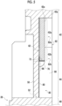
Fig. 1 is a side sectional view showing an eccentric oscillation type speed reducer according to a first embodiment. -
Fig. 2 is an exploded perspective view showing a synchronous carrier of the first embodiment together with a peripheral structure. -
Fig. 3 is a front view showing the synchronous carrier of the first embodiment. -
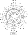
Fig. 4 is a front view showing the synchronous carrier of the first embodiment together with the peripheral structure. -
Fig. 5 is an enlarged view showing a strain sensor ofFig. 1 . -
Fig. 6 is an enlarged view showing the strain sensor ofFig. 4 . -
Fig. 7 is a side sectional view showing an eccentric oscillation type speed reducer according to a second embodiment. -
Fig. 8 is a view showing the eccentric oscillation type speed reducer of the second embodiment as viewed from the same viewpoint as that inFig. 4 . -
Fig. 9 is a view showing an eccentric oscillation type speed reducer of a third embodiment as viewed from the same viewpoint as that inFig. 6 . - Embodiments for implementing an eccentric oscillation type speed reducer (hereinafter, also referred to as a speed reducer) of the present disclosure will be described. Identical or equivalent elements will be denoted by the same reference numerals and the repeated description thereof will be omitted. In each drawing, for convenience of description, the components are appropriately omitted, enlarged, or reduced. The drawings shall be viewed according to the directions of the symbols.
-
Fig. 1 is referred to. Aspeed reducer 10 includes acrankshaft 14 having at least oneeccentric body 12, anexternal gear 16 capable of being oscillated by theeccentric body 12, aninternal gear 18 that meshes with theexternal gear 16, asynchronous carrier 20 capable of being synchronized with an axial rotation component of theexternal gear 16, acasing 22 that is disposed outside theexternal gear 16 in a radial direction, and anasynchronous carrier 24 provided on a side opposite to thesynchronous carrier 20 in an axial direction with respect to theexternal gear 16. In the present embodiment, a center crank type eccentric oscillationtype speed reducer 10 will be described. In thespeed reducer 10 of this type, thecrankshaft 14 is disposed on an oscillation center C16a of theexternal gear 16. Hereinafter, the direction along the oscillation center C16a of theexternal gear 16 will be referred to as an axial direction, and the radial direction and the circumferential direction centered on the oscillation center C16a will be referred to as a radial direction and a circumferential direction. - The
speed reducer 10 includes afixed body 28 that is fixed to anexternal member 26, and anoutput body 32 that outputs rotation to an external drivenmember 30. Here, an example in which thesynchronous carrier 20 and thecasing 22 configure thefixed body 28 and theinternal gear 18 and theasynchronous carrier 24 configure theoutput body 32 will be described. Theexternal member 26 is provided outside thespeed reducer 10 and supports thespeed reducer 10. The drivenmember 30 is provided outside thespeed reducer 10 and is driven by the output of theoutput body 32. The drivenmember 30 is, for example, a part of each of various machines such as industrial machines (machine tools, construction machines, or the like), robots (industrial robots, service robots, or the like), and transport equipment (conveyors, vehicles, or the like). When rotation is input from a drive source (not shown) to thecrankshaft 14, theoutput body 32 outputs the rotation decelerated more than the rotation of thecrankshaft 14 to the drivenmember 30. The drive source is, for example, a motor. However, in addition to the motor, a gear motor, an engine, or the like may be used as the drive source. - The
eccentric body 12 has a circular shape eccentric with respect to a rotation center line C14 of thecrankshaft 14. Theeccentric body 12 can oscillate theexternal gear 16 by rotating around the rotation center line C14 of thecrankshaft 14. Here, the term "oscillation" means that a gear center C16b of theexternal gear 16 rotates around the oscillation center C16a. The number of theeccentric bodies 12 is not particularly limited, and one or three or moreeccentric bodies 12 may be provided. - The
external gear 16 is individually provided to correspond to each of the plurality ofeccentric bodies 12, and is supported by a correspondingeccentric body 12 via aneccentric bearing 34. Theinternal gear 18 includes an internal gearmain body 18a and a plurality ofinner teeth 18b provided in an inner peripheral portion of the internal gearmain body 18a and meshing with theexternal gear 16. The plurality ofinner teeth 18b may be integrally provided by the same member as the internal gearmain body 18a, or may be configured by a plurality of pins that are rotatably supported by the internal gearmain body 18a. - A
pin 36 protrudes in the axial direction from thesynchronous carrier 20. A plurality ofpins 36 are provided at intervals in the circumferential direction. Thepin 36 may be configured by the same member as thesynchronous carrier 20, or may be configured by a member different from thesynchronous carrier 20. Thepin 36 penetrates theexternal gear 16 in the axial direction, and can receive a load from theexternal gear 16 when theexternal gear 16 oscillates. - The expression, the
synchronous carrier 20 is "synchronized with the axial rotation component of theexternal gear 16", means that the axial rotation component of thesynchronous carrier 20 is maintained at the same magnitude as the axial rotation component of theexternal gear 16 within a numerical range including zero. For example, in a case where, as in the present embodiment, theinternal gear 18 serves as theoutput body 32 and thesynchronous carrier 20 serves as thefixed body 28, theinternal gear 18 rotates during the operation of thespeed reducer 10. In this case, thesynchronous carrier 20 is fixed to theexternal member 26, so that the axial rotation component of thesynchronous carrier 20 is maintained at zero. In addition, the rotation of theexternal gear 16 is restrained by thesynchronous carrier 20 and thepin 36. In this manner, the axial rotation component of theexternal gear 16 is also maintained at zero. As a result, the axial rotation component of thesynchronous carrier 20 is synchronized with the axial rotation component of theexternal gear 16. In contrast, in a case where theinternal gear 18 serves as thefixed body 28 and thesynchronous carrier 20 serves as theoutput body 32, theexternal gear 16 rotates during the operation of thespeed reducer 10. The axial rotation component of theexternal gear 16 is transmitted to thesynchronous carrier 20 via thepin 36. In this way, thesynchronous carrier 20 rotates with the axial rotation component having the same magnitude as the axial rotation component of theexternal gear 16, and thus is synchronized with the axial rotation component of theexternal gear 16. - The
asynchronous carrier 24 is not connected to thesynchronous carrier 20, and is not synchronized with the axial rotation component of thesynchronous carrier 20 during the operation of thespeed reducer 10. As in the present embodiment, a case where thesynchronous carrier 20 serves as thefixed body 28 and the axial rotation component thereof is maintained at zero is considered. In this case, theasynchronous carrier 24 serves as theoutput body 32 and rotates, and thus theasynchronous carrier 24 is not synchronized with the axial rotation component of thesynchronous carrier 20. In contrast, a case where thesynchronous carrier 20 serves as theoutput body 32 and rotates is considered. In this case, theasynchronous carrier 24 serves as thefixed body 28 and maintains the axial rotation component at zero, and thus theasynchronous carrier 24 is not synchronized with the axial rotation component of thesynchronous carrier 20. - The
casing 22 of the present embodiment is provided separately from theinternal gear 18. Thecasing 22 of the present embodiment is fixed to thesynchronous carrier 20 by a fixture such as a bolt (not shown) to be integrated with thesynchronous carrier 20. - An example of the operation of the
speed reducer 10 described above will be described. When rotation is input from the drive source to thecrankshaft 14, theeccentric body 12 of thecrankshaft 14 causes theexternal gear 16 to oscillate. In a case where theexternal gears 16 oscillate, the meshing position between theexternal gears 16 and theinternal gear 18 change in the circumferential direction. Accordingly, one (here, the internal gear 18) of theexternal gear 16 and theinternal gear 18 rotates each time thecrankshaft 14 rotates once. Theoutput body 32 is rotated by the axial rotation component of one of theexternal gear 16 and theinternal gear 18, and outputs rotation to the drivenmember 30. In this case, theoutput body 32 outputs the rotation decelerated at a reduction ratio corresponding to a difference in the number of teeth between theexternal gear 16 and theinternal gear 18 with respect to the rotation input to thecrankshaft 14 to the drivenmember 30. -
Figs. 1 to 3 are referred to. Thespeed reducer 10 includes astrain sensor 60 that is installed in a distortion generating portion 44 (to be described later) of the fixedbody 28, and acircuit board 62 that is electrically connected to thestrain sensor 60. In addition to these, thespeed reducer 10 has a feature regarding the structure of the fixedbody 28. - The fixed
body 28 includes afirst ring portion 40, asecond ring portion 42 that is provided to be separated from thefirst ring portion 40 in the radial direction and is fixed to theexternal member 26, and thedistortion generating portion 44 that is provided between thefirst ring portion 40 and thesecond ring portion 42. Thefirst ring portion 40, thesecond ring portion 42, and thedistortion generating portion 44 of the present embodiment are provided in thesynchronous carrier 20. In the present embodiment, these are provided in a single member configuring thesynchronous carrier 20. - The
first ring portion 40 has a ring shape. Thesecond ring portion 42 has a ring shape. Thefirst ring portion 40 of the present embodiment serves as an inner ring portion provided on the inner side in the radial direction, and thesecond ring portion 42 serves as an outer ring portion provided on the outer side in the radial direction. - Torque is input to the
first ring portion 40 during the operation of thespeed reducer 10. Specifically, the torque is transmitted from any one of theexternal gear 16 and theinternal gear 18 during the operation of thespeed reducer 10, thereby being input to thefirst ring portion 40. A case where thesynchronous carrier 20 is at least a part of the fixedbody 28, as in the present embodiment, is considered. In this case, the torque transmitted from theexternal gear 16 is input to thefirst ring portion 40 of the fixedbody 28 via thepin 36. In contrast, as in the embodiment ofFig. 7 described later, a case where theinternal gear 18 is at least a part of the fixedbody 28 is considered. In this case, the torque transmitted from theinner teeth 18b of theinternal gear 18 is input to thefirst ring portion 40 of the fixedbody 28. - The
second ring portion 42 includes afirst fixation portion 46 that is fixed to theexternal member 26. Thefirst fixation portion 46 of the present embodiment is directly fixed to theexternal member 26 by afixture 48 such as a bolt. InFig. 1 , only the center line of the bolt serving as thefixture 48 is shown. InFig. 1 , only the center line is shown for a use location of the other bolt in the same manner. First through-holes 46a for thefixtures 48 are formed in thefirst fixation portion 46 of the present embodiment at intervals in the circumferential direction. In addition, thefirst fixation portion 46 may be fixed to theexternal member 26 via another constituent member (for example, the casing 22) of the fixedbody 28. - The
distortion generating portion 44 connects thefirst ring portion 40 and thesecond ring portion 42. Thedistortion generating portion 44 is deformable while transmitting the torque transmitted to thefirst ring portion 40 to thesecond ring portion 42. In a case where such torque is applied, thedistortion generating portion 44 is configured to be deformable in the circumferential direction more than thefirst ring portion 40 and thesecond ring portion 42. It can be said that the amount of deformation of thedistortion generating portion 44 in the circumferential direction is larger than those of thefirst ring portion 40 and thesecond ring portion 42. - In order to increase the amount of deformation of the
distortion generating portion 44 in this manner, thedistortion generating portion 44 of the present embodiment is configured by a plurality ofpillar portions 50 provided at intervals in the circumferential direction. A specific example for increasing the amount of deformation of thedistortion generating portion 44 in this manner is not particularly limited. In order to realize this, for example, thedistortion generating portion 44 may have a reduced axial dimension with respect to both thefirst ring portion 40 and thesecond ring portion 42. In this case, thedistortion generating portion 44 may have a ring shape that is continuous in the circumferential direction. - The plurality of
pillar portions 50 of the present embodiment are provided to extend radially when viewed in the axial direction. A specific shape of thepillar portion 50 is not particularly limited. For example, thepillar portion 50 may have a linear shape, a curved shape, a crank shape, or the like when viewed in the axial direction. - The fixed
body 28 includes an axial through-hole 52 formed between thepillar portions 50 adjacent to each other. The axial through-hole 52 penetrates the fixedbody 28 in the axial direction. In the present embodiment, a plurality of axial through-holes 52 are formed at intervals in the circumferential direction. The axial through-hole 52 includes a pair ofcircumferential side portions 52a configured by thepillar portions 50 adjacent to each other, and a pair ofradial side portions first ring portion 40 and thesecond ring portion 42. The pair ofradial side portions radial side portion 52b that is configured by an outer peripheral portion of thering portion 40 located on the inner side in the radial direction, and an outerradial side portion 52c that is configured by an inner peripheral portion of thering portion 42 located on the outer side in the radial direction. -
Figs. 4 ,5 , and6 are referred to. Thestrain sensor 60 is used to detect the torque that acts on the fixedbody 28. Thestrain sensor 60 is installed on the axial side surface of thedistortion generating portion 44 by adhesion or the like. Thestrain sensor 60 detects an electrical signal corresponding to the strain when thedistortion generating portion 44 of the fixedbody 28 is deformed. The electrical signal detected by thestrain sensor 60 indicates the strain of thedistortion generating portion 44. Thestrain sensor 60 of the present embodiment detects an electrical signal indicating shear strain of thedistortion generating portion 44 in a direction perpendicular to the axial direction. - The
strain sensor 60 of the present embodiment is a strain gauge. However, a specific example thereof is not particularly limited. The strain gauge may be a uniaxial gauge using a single gauge element made of a resistance wire, or a multiaxial gauge such as a rosette gauge using a plurality of gauge elements. Here, a biaxial gauge using twogauge elements gauge elements distortion generating portion 44 of the fixedbody 28 to detect an electrical signal indicating a strain in a detection direction corresponding to each of thegauge elements gauge elements first gauge element 64A for detecting the shear strain in a first detection direction D1, and asecond gauge element 64B for detecting the shear strain in a second detection direction D2 perpendicular to the first detection direction D1. - The
strain sensor 60 includes asensor electrode 66 for outputting the detected electrical signal. Thesensor electrode 66 of the present embodiment is a pad electrode provided on the main surface (axial side surface) of thestrain sensor 60. However, a specific example thereof is not particularly limited. Thesensor electrodes 66 of the present embodiment are individually provided to correspond to each of thegauge elements gauge elements - In the present embodiment, a plurality of
strain sensors 60 are installed at intervals in the circumferential direction. Specifically, in the present embodiment, a total of fourstrain sensors 60 are installed at intervals in the circumferential direction. Thestrain sensors 60 are wired to configure a bridge circuit (not shown) in accordance with a predetermined wiring method (one-gauge method, two-gauge method, four-gauge method, or the like). Here, a wiring method such as the four-gauge method using fourstrain sensors 60 is exemplified. In addition to this, as the wiring method, a one-gauge method using onestrain sensor 60, a two-gauge method using twostrain sensors 60, or the like may be used. The number and the disposition position of thestrain sensors 60 are not limited thereto, and may be appropriately changed. - The
strain sensor 60 is electrically connected to aprocessing device 68 for detecting the torque via thecircuit board 62. Theprocessing device 68 is, for example, a combination of a CPU, a ROM, and a RAM, such as a microcomputer, and is configured by, for example, a processing chip or the like. Theprocessing device 68 may be mounted on thecircuit board 62, or may be present outside thespeed reducer 10. - The
strain sensor 60 outputs an electrical signal indicating the strain of thedistortion generating portion 44 to theprocessing device 68 via the bridge circuit described above. Theprocessing device 68 can detect the torque acting on the fixedbody 28 by processing the electrical signal output from thestrain sensor 60. As a processing method for detecting torque from an electrical signal of thestrain sensor 60, in addition to a known method, a method that can be used in the future may be used and a detailed description thereof will be omitted. - A
circuit element 70 that is used to process the electrical signal of thestrain sensor 60 is mounted on thecircuit board 62. Thecircuit element 70 is, for example, an amplifier that amplifies the electrical signal of thestrain sensor 60, a processing chip that configures theprocessing device 68, an A/D converter, or the like. Thecircuit element 70 is mounted on a mountingsurface 62d provided on the main surface of thecircuit board 62. - The
circuit board 62 includes a plurality ofsubstrate electrodes 72 for electrically connecting thecircuit board 62 to thestrain sensor 60. Thesubstrate electrode 72 of the present embodiment is an end surface through-hole electrode provided on an end surface (a tip end surface of afirst protrusion portion 62b to be described later) of thecircuit board 62. The type of thesubstrate electrode 72 is not particularly limited, and may be a pad electrode provided on the main surface of thecircuit board 62. The plurality ofsubstrate electrodes 72 configure anelectrode group 74 including a plurality of (here, four)substrate electrodes 72. Thecircuit board 62 of the present embodiment includes a plurality of sets ofelectrode groups 74. The plurality of sets ofelectrode groups 74 are provided at intervals in the circumferential direction of thecircuit board 62. Theelectrode group 74 corresponds to onestrain sensor 60, and each of thesubstrate electrodes 72 belonging to theelectrode group 74 is electrically connected to each of thesensor electrodes 66 of acorresponding strain sensor 60. The number and positions of thesensor electrodes 66 and thesubstrate electrodes 72 are not particularly limited. - The
strain sensor 60 and thecircuit board 62 are electrically connected to each other via aconductive connection material 76 that is in contact with thestrain sensor 60 and thecircuit board 62. Specifically, thesensor electrode 66 of thestrain sensor 60 and thesubstrate electrode 72 of thecircuit board 62 to be electrically connected to each other are electrically connected to each other via theconductive connection material 76 that is in contact with thesensor electrode 66 and thesubstrate electrode 72. Theconductive connection material 76 of the present embodiment is solder, but may be a conductive resin or the like, in addition to solder. Thecircuit board 62 and thestrain sensor 60 of the present embodiment are directly connected to each other by theconductive connection material 76, but may be connected to each other by using a wire such as a bonding wire and theconductive connection material 76. An electrical signal that is output from thestrain sensor 60 sequentially passes through thesubstrate electrode 72 of thecircuit board 62 and a conductor pattern 78 (refer toFig. 6 ) of thecircuit board 62, and is sent to other locations such as thecircuit element 70. - The effects of the
speed reducer 10 described above will be described. - (A) When torque is input to the
first ring portion 40 during the operation of thespeed reducer 10, thedistortion generating portion 44 of the fixedbody 28 is deformed while transmitting the torque. Thestrain sensor 60 is installed in thedistortion generating portion 44 of the fixedbody 28. Therefore, the torque acting on the fixedbody 28 can be detected by using the electrical signal corresponding to the strain of thedistortion generating portion 44 detected by thestrain sensor 60. - As described above, the
processing device 68 processes the electrical signal, whereby the torque can be detected. In providing the eccentric oscillationtype speed reducer 10 capable of detecting the torque, theprocessing device 68 is not essential, and thespeed reducer 10 does not need to include theprocessing device 68. - The
distortion generating portion 44 of the fixedbody 28 is configured to be more deformable than each of thering portions body 28, and is likely to increase the strain when the torque acts. By installing thestrain sensor 60 at a location where the strain is likely to be increased, the electrical signal that is detected by thestrain sensor 60 can be increased as compared to a case where thestrain sensor 60 is installed on each of thering portions body 28. As a result, compared to such a case, even though the torque acting on thefirst ring portion 40 of the fixedbody 28 is small, the torque can be easily detected by using the electrical signal. - Next, other features of the
speed reducer 10 of the present embodiment will be described.Figs. 3 and5 are referred to. Thedistortion generating portion 44 of the fixedbody 28 includes a first recessedportion 80 that accommodates thestrain sensor 60. The first recessedportion 80 is provided on the axial side surface of the fixedbody 28. The first recessedportion 80 is provided between thefirst ring portion 40 and thesecond ring portion 42, and is recessed in the axial direction with respect to the axial side surface of at least one (here, the first ring portion 40) of thefirst ring portion 40 and thesecond ring portion 42. The first recessedportion 80 of the present embodiment is also recessed in the axial direction with respect to the axial side surface of areinforcement portion 90 provided in thedistortion generating portion 44 to be described later. Thestrain sensor 60 is installed on a bottom surface portion of the first recessedportion 80 by using adhesion or the like. - One of the
first ring portion 40 and thesecond ring portion 42 of the fixedbody 28 includes a second recessedportion 82 that accommodates at least a part of thecircuit board 62. The second recessedportion 82 is provided on the axial side surface of the fixedbody 28. The second recessedportion 82 of the present embodiment is provided on the axial side surface of thesecond ring portion 42, and is recessed in the axial direction with respect to an axialouter side surface 42a of thesecond ring portion 42 that is located on the outer side in the axial direction with respect to the second recessedportion 82. Thecircuit board 62 is installed on a bottom surface portion of the second recessedportion 82 by using adhesion or the like. An internal space of the second recessedportion 82 of the present embodiment is continuous with an internal space of the first recessedportion 80. The bottom surface portion of the second recessedportion 82 and the bottom surface portion of the first recessedportion 80 of the present embodiment are continuous to be flush with each other. - The second recessed
portion 82 includes acircumferential extension portion 82a extending in the circumferential direction when viewed in the axial direction, a firstradial extension portion 82b extending in the radial direction from thecircumferential extension portion 82a toward thedistortion generating portion 44 side, and a secondradial extension portion 82c extending in the radial direction from thecircumferential extension portion 82a toward the axial through-hole 52 side. Here, for convenience of description, inFig. 3 , the position of each portions is shown by a two-dot chain line. Thecircumferential extension portion 82a is partially shown. Thecircumferential extension portion 82a of the present embodiment extends to be continuous in an annular shape, but may be provided in only a part of the circumferential range. The firstradial extension portion 82b of the present embodiment is individually provided to correspond to each of the plurality ofpillar portions 50. A plurality of firstradial extension portions 82b are provided at intervals in the radial direction. The secondradial extension portion 82c of the present embodiment is individually provided to correspond to each of the plurality of axial through-holes 52. A plurality of secondradial extension portion 82c is provided at intervals in the radial direction. -
Figs. 4 and5 are referred to. Thecircuit board 62 includes anannular portion 62a facing one of thefirst ring portion 40 and thesecond ring portion 42 in the axial direction, thefirst protrusion portion 62b protruding in the radial direction from theannular portion 62a, and asecond protrusion portion 62c protruding in the radial direction from theannular portion 62a. A mountingsurface 62d of thecircuit board 62 is mainly provided in thesecond protrusion portion 62c in addition to theannular portion 62a of thecircuit board 62. - The
annular portion 62a has an annular shape extending in the circumferential direction. In order to realize this, theannular portion 62a of the present embodiment is continuous in an annular shape, but may be provided in only a part of the circumferential range. Theannular portion 62a of the present embodiment faces thesecond ring portion 42 in the axial direction and is installed on the facingsecond ring portion 42 by using an adhesive or the like. Theannular portion 62a of the present embodiment faces the second recessedportion 82 of thesecond ring portion 42 in the axial direction. Thecircuit board 62 is installed on the fixedbody 28 in thering portion 42, which is a location different from thedistortion generating portion 44 that is the installation location of thestrain sensor 60. Theannular portion 62a is accommodated in thecircumferential extension portion 82a of the second recessedportion 82 of the fixedbody 28. - The
first protrusion portion 62b protrudes toward the side of thedistortion generating portion 44 of the fixedbody 28 in the radial direction with respect to theannular portion 62a. Thefirst protrusion portion 62b of the present embodiment protrudes into the first recessedportion 80, in which thedistortion generating portion 44 is located, with respect to theannular portion 62a. Thefirst protrusion portion 62b is accommodated in the firstradial extension portion 82b of the second recessedportion 82 in addition to the first recessedportion 80 of the fixedbody 28. Thesubstrate electrode 72 is provided at thefirst protrusion portion 62b. Thefirst protrusion portion 62b is connected to thestrain sensor 60 by theconductive connection material 76, as described above. - The
second protrusion portion 62c protrudes to the same side as thefirst protrusion portion 62b in the radial direction with respect to theannular portion 62a. Thesecond protrusion portion 62c is provided at a location overlapping the internal space of the axial through-hole 52 of the fixedbody 28 when viewed in the axial direction. Thesecond protrusion portion 62c protrudes from theannular portion 62a of thecircuit board 62 to be located between thepillar portions 50 adjacent to each other when viewed in the axial direction. Thesecond protrusion portion 62c protrudes in the radial direction more than thefirst protrusion portion 62b with respect to theannular portion 62a. Thesecond protrusion portion 62c is partially accommodated in the secondradial extension portion 82c (refer toFig. 3 ) of the second recessedportion 82 of the fixedbody 28. - The effects of the features described above will be described.
- (B) The
distortion generating portion 44 includes the first recessedportion 80 that accommodates thestrain sensor 60. Therefore, thestrain sensor 60 can be made less likely to interfere with other members as compared to a case where the first recessedportion 80 is not provided in thedistortion generating portion 44. - (C) The
second ring portion 42 of the fixedbody 28 includes the second recessedportion 82 that accommodates thecircuit board 62. Therefore, thecircuit board 62 can be made less likely to interfere with the other member as compared to a case where the second recessedportion 82 is not provided in thesecond ring portion 42. This effect can also be obtained in a case where the second recessedportion 82 is provided in thefirst ring portion 40 instead of thesecond ring portion 42. - (D) The
circuit board 62 includes thefirst protrusion portion 62b that protrudes into the first recessedportion 80 of the fixedbody 28 and is electrically connected to thestrain sensor 60. Therefore, compared to a case where thecircuit board 62 does not include thefirst protrusion portion 62b, thefirst protrusion portion 62b serving as a part of thecircuit board 62 can be present near thestrain sensor 60 in the first recessedportion 80. As a result, thecircuit board 62 and thestrain sensor 60 are easily electrically connected to each other by using thefirst protrusion portion 62b. - (E) The
circuit board 62 includes theannular portion 62a facing thesecond ring portion 42 in the axial direction, and thefirst protrusion portion 62b that protrudes in the radial direction from theannular portion 62a and is connected to thestrain sensor 60. Therefore, compared to a case where thecircuit board 62 does not include thefirst protrusion portion 62b, thefirst protrusion portion 62b serving as a part of thecircuit board 62 can be present near thestrain sensor 60 installed in thedistortion generating portion 44 of the fixedbody 28. As a result, thecircuit board 62 and thestrain sensor 60 are easily connected to each other by using thefirst protrusion portion 62b. This effect can also be obtained in a case where, instead of thesecond ring portion 42, thefirst ring portion 40 faces theannular portion 62a of thecircuit board 62 in the axial direction. - (F) The
circuit board 62 includes thesecond protrusion portion 62c that protrudes to be located between thepillar portions 50, which are adjacent to each other, of the fixedbody 28. Therefore, a part of thecircuit board 62 can also be present between thepillar portions 50, which are adjacent to each other, of the fixedbody 28, and accordingly, it is advantageous to an increase in the area of the mountingsurface 62d on which thecircuit element 70 is mounted. -
Figs. 3 and5 are referred to. The fixedbody 28 includes thereinforcement portion 90 provided at thepillar portion 50. Thereinforcement portion 90 of the present embodiment is provided to be paired at each of the circumferential side surfaces of thepillar portion 50. Thereinforcement portion 90 is configured by a protrusion portion that protrudes outward in the axial direction in thepillar portion 50. Thereinforcement portion 90 is provided to reinforce thepillar portion 50. Thereinforcement portion 90 of the present embodiment is provided to suppress bending strain of thepillar portion 50 by increasing the stiffness of thepillar portion 50 against bending deformation. The terms, bending deformation and bending strain, as referred to herein refer to deformation and strain caused by a moment load acting to tilt the rotation center line of theoutput body 32. In this way, it is advantageous to accurate detection of the torque by using an electrical signal indicating the shear strain of thedistortion generating portion 44. In order to realize this, thereinforcement portion 90 of the present embodiment includes aradial extension portion 90a provided at a circumferential side portion of thepillar portion 50 and extending in the radial direction. In addition, thereinforcement portion 90 of the present embodiment includes acircumferential extension portion 90b extending in the circumferential direction from the end portion of theradial extension portion 90a provided at thering portion 42. Thecircumferential extension portion 90b extends from the end portion of theradial extension portion 90a toward the outer side in the circumferential direction with respect to thepillar portion 50 in which thereinforcement portion 90 is provided. - The
reinforcement portion 90 of the present embodiment protrudes in the axial direction from the bottom surface portions of the first and second recessedportions radial extension portion 90a of thereinforcement portion 90 partially forms the first recessedportion 80 and the firstradial extension portion 82b of the second recessedportion 82. Thecircumferential extension portion 90b of thereinforcement portion 90 partially forms thecircumferential extension portion 82a of the second recessedportion 82. - The
reinforcement portion 90 described above is provided to be paired at each of the pair of thecircumferential side portions 52a of the axial through-hole 52. The pair ofreinforcement portions 90 are interrupted in the outerradial side portion 52c, which is located on the second recessedportion 82 side of the fixedbody 28 in the radial direction with respect to the axial through-hole 52, out of the pair ofradial side portions hole 52. InFig. 3 , a location S1 where the pair ofreinforcement portions 90 are interrupted is shown by a two-dot chain lines. The term "interrupted" as referred to herein means that the pair ofreinforcement portions 90 are not continuous in theradial side portion 52c in question when viewed in the axial direction, and are provided at an interval. The secondradial extension portion 82c that is a part of the second recessedportion 82 is provided at theradial side portion 52c of the axial through-hole 52, which is located at the location S1 where the pair ofreinforcement portions 90 are interrupted. Thesecond protrusion portion 62c of thecircuit board 62 protrudes to be located between thepillar portions 50 adjacent to each other, while passing through the location S1 where the pair ofreinforcement portions 90 are interrupted, when viewed in the axial direction. - (G) In this way, the location S1 where the pair of
reinforcement portions 90 are interrupted can be used as a disposition space for thecircuit board 62 that is accommodated in the second recessedportion 82 of the fixedbody 28, and thus it is advantageous to an increase in the area of the mounting surface on which thecircuit element 70 is mounted. In addition, thepillar portion 50 of the fixedbody 28 can be reinforced by the pair ofreinforcement portions 90 while securing the disposition space for thecircuit board 62 in this way. -
Fig. 1 is referred to. Amain bearing 92 is disposed between the fixedbody 28 and theoutput body 32. Themain bearing 92 of the present embodiment is disposed between thecasing 22 and theinternal gear 18. In addition, themain bearing 92 may be disposed between thecasing 22 and theasynchronous carrier 24. Themain bearing 92 can transmit the moment load input from the drivenmember 30 to theoutput body 32 to the fixedbody 28. In order to realize this, themain bearing 92 of the present embodiment is configured by a cross roller bearing, but may be configured by a four-point contact ball bearing or the like. In addition, in order to realize this, a plurality ofmain bearings 92 may be provided at intervals in the axial direction. In this case, themain bearing 92 may be configured by various bearings such as a deep groove ball bearing and an angular ball bearing. - The fixed
body 28 includes thefixation portions external member 26. Thefixation portions second fixation portion 94 that is provided in thecasing 22, in addition to thefirst fixation portion 46 that is provided in thesecond ring portion 42 of thesynchronous carrier 20. Thefirst fixation portion 46 of thesynchronous carrier 20 and thesecond fixation portion 94 of thecasing 22 of the present embodiment are fixed to theexternal member 26 by thecommon fixture 48. Thesecond fixation portion 94 of thecasing 22 has a second through-hole 94a which is formed at a location overlapping the first through-hole 46a in the axial direction, and through which thefixture 48 passes. - The
speed reducer 10 is provided with aload transmission pathway 96 extending from theoutput body 32 to theexternal member 26 via themain bearing 92 and the fixedbody 28. Here, a part of theload transmission pathway 96 is shown by an arrow. Theload transmission pathway 96 can transmit the load input from the drivenmember 30 to theoutput body 32 to theexternal member 26. The "load" mainly assumes a moment load, but may include an axial load or a radial load. In the present embodiment, in addition to thesecond fixation portion 94 of thecasing 22 of the fixedbody 28, thefirst fixation portion 46 of thesecond ring portion 42 of thesynchronous carrier 20 is provided on theload transmission pathway 96. - The
distortion generating portion 44 of the fixedbody 28 is provided at a location different from theload transmission pathway 96. In addition to thedistortion generating portion 44, thefirst ring portion 40 of the fixedbody 28 is also provided at a location different from theload transmission pathway 96. Thedistortion generating portion 44 is provided at a location different from theload transmission pathway 96 for transmitting a moment load, even though torque is transmitted from thefirst ring portion 40 during the operation of thespeed reducer 10. In order to satisfy this condition, thedistortion generating portion 44 of the present embodiment is provided in a part of thesynchronous carrier 20 which is integrated with thecasing 22, and to which torque is transmitted from theexternal gear 16 via thepin 36. In integrating thecasing 22 and thesynchronous carrier 20 in this way, thesecond ring portion 42 of thesynchronous carrier 20 may be directly fixed to theexternal member 26, as in the present embodiment, or may be fixed to theexternal member 26 via thecasing 22 directly fixed to theexternal member 26. In addition, in providing thedistortion generating portion 44 at a location different from theload transmission pathway 96, thedistortion generating portion 44 of the present embodiment is provided at a position shifted inward in the radial direction with respect to thesecond ring portion 42 fixed to theexternal member 26. - When a moment load acts on the
distortion generating portion 44 of the fixedbody 28 to increase the bending strain occurred in thedistortion generating portion 44, it is known that this causes a decrease in detection accuracy in detecting the torque by using the electrical signal of thestrain sensor 60 indicating the shear strain of thedistortion generating portion 44. Thedistortion generating portion 44 of the fixedbody 28 is provided at a location different from theload transmission pathway 96 through which the moment load that causes such a decrease in detection accuracy is transmitted. In this way, it is difficult for bending strain to occur in thedistortion generating portion 44, which is advantageous to accurate detection of the torque, as described above. -
Fig. 7 is referred to. In the subsequent embodiments, the same contents as those in the first embodiment are applied to components that are not described below, among the components described in the first embodiment. - In the
speed reducer 10 of the embodiment ofFig. 1 , thecasing 22 and theinternal gear 18 are provided separately. In contrast, thespeed reducer 10 of the present embodiment is different in that thecasing 22 and theinternal gear 18 are integrated with each other. In order to satisfy this condition, at least the internal gearmain body 18a among the internal gearmain body 18a and the plurality ofinner teeth 18b configuring theinternal gear 18 may be integrated with thecasing 22. - In the
speed reducer 10 of the embodiment ofFig. 1 , thesynchronous carrier 20 and theasynchronous carrier 24 are provided on both sides of theexternal gear 16 in the axial direction. In contrast, in thespeed reducer 10 of the present embodiment, a pair ofsynchronous carriers 20 are provided on both sides of theexternal gear 16 in the axial direction. Thesynchronous carriers 20 are connected to each other via thepin 36, and both of thesynchronous carriers 20 can be synchronized with the axial rotation component of theexternal gear 16. - The fixed
body 28 of the embodiment ofFig. 1 is configured by thesynchronous carrier 20 and thecasing 22, and theoutput body 32 is configured by theasynchronous carrier 24 and theinternal gear 18. In contrast, the fixedbody 28 of the present embodiment is configured by theinternal gear 18 and thecasing 22, and theoutput body 32 is configured by each of thesynchronous carriers 20. Unlike the form inFig. 1 , a pair ofmain bearings 92 are disposed at an interval in the axial direction between theoutput body 32 and the fixedbody 28. Each of the pair ofmain bearings 92 is disposed between the individualsynchronous carrier 20 and thecasing 22. - The first and
second ring portions distortion generating portion 44 of the fixedbody 28 according to the present embodiment are provided in thecasing 22 integrated with theinternal gear 18. These are provided in a single member configuring thecasing 22, as in the embodiment ofFig. 1 . Thefirst ring portion 40 of the fixedbody 28 configures an inner ring portion, and thesecond ring portion 42 configures an outer ring portion. A plurality ofinner teeth 18b are provided in the inner peripheral portion of thefirst ring portion 40 of the present embodiment. In addition, themain bearing 92 is disposed in the inner peripheral portion of thefirst ring portion 40 of the present embodiment. In a case where theinternal gear 18 serves as at least a part of the fixedbody 28, as in the present embodiment, the torque transmitted from theinner teeth 18b of theinternal gear 18 is input to thefirst ring portion 40 of the fixedbody 28. -
Fig. 8 is referred to. Thedistortion generating portion 44 of the fixedbody 28 of the present embodiment also includes the first recessedportion 80 that accommodates thestrain sensor 60. In addition, thesecond ring portion 42 of the fixedbody 28 of the present embodiment also includes the second recessedportion 82 that accommodates thecircuit board 62. Thecircuit board 62 of the present embodiment also includes thefirst protrusion portion 62b that protrudes into the first recessedportion 80 of the fixedbody 28. - In this manner, the
speed reducer 10 of the present embodiment includes the components described in (A) to (E) described above, and it is possible to obtain the effects corresponding to the description thereof. In addition, thespeed reducer 10 of the present embodiment has the feature regarding thereinforcement portion 90 of the fixedbody 28 of (G), in addition to thesecond protrusion portion 62c of thecircuit board 62 of (F) described above, and it is possible to obtain the effects corresponding to the description thereof. - In the
speed reducer 10 of the present embodiment, unlike the first embodiment, thedistortion generating portion 44 of the fixedbody 28 is provided in theload transmission pathway 96 extending from theoutput body 32 to theexternal member 26 via themain bearing 92 and the fixedbody 28. In this case, unlike the first embodiment, the moment load is transmitted to thedistortion generating portion 44 of the fixedbody 28, and thus, a decrease in detection accuracy may be caused in detecting the torque by using the electrical signal of thestrain sensor 60 that indicates the shear strain of thedistortion generating portion 44. As a countermeasure to this, various methods including a known method may be adopted to suppress the influence of the bending strain occurred in thedistortion generating portion 44. - As the method, for example, a dedicated strain sensor for detecting a bending strain occurred in the fixed
body 28 may be installed in the fixedbody 28. In this case, the bending strain component included in the electrical signal of thestrain sensor 60 may be reduced by correcting the electrical signal of thestrain sensor 60 indicating the shear strain of thedistortion generating portion 44, based on the electrical signal of the dedicated strain sensor indicating the bending strain of thedistortion generating portion 44. - In addition, as the method, by installing the
individual strain sensor 60 on each of both sides in the axial direction of thedistortion generating portion 44 of the fixedbody 28 and disposing theindividual strain sensor 60 on the opposite side of the bridge circuit, the bending strain component included in the electrical signal of theindividual strain sensors 60 may be canceled. - In addition to this, a machine learning model may be used to suppress the influence of the bending strain component included in the electrical signal of the
strain sensor 60. The machine learning model is trained to output torque in which the influence of a bending strain component included in the electrical signal of thestrain sensor 60 is reduced, in a case where the electrical signal of thestrain sensor 60 indicating the shear strain of thedistortion generating portion 44 is input. The machine learning model is, for example, a neural network such as an artificial neuronal network (ANN). -
Fig. 9 is referred to. Theentire circuit board 62 of the first embodiment is configured by a rigid substrate. Theannular portion 62a of thecircuit board 62 of the present embodiment is configured by arigid substrate 100, and thefirst protrusion portion 62b is configured by aflexible substrate 102. Theflexible substrate 102 is connected to therigid substrate 100 by various connection methods including a known method. Thesecond protrusion portion 62c is configured by therigid substrate 100 that is common to theannular portion 62a, but may be configured by theflexible substrate 102. In addition, both theannular portion 62a and thefirst protrusion portion 62b of thecircuit board 62 may be configured by theflexible substrate 102. - When the
distortion generating portion 44 is deformed more than each of thering portions body 28, thestrain sensor 60 installed in thedistortion generating portion 44 and thecircuit board 62 installed in thering portion 42 try to relatively move in the circumferential direction. Theflexible substrate 102 can be flexibly deformed to follow the relative movement between thecircuit board 62 and thestrain sensor 60. In this case, theflexible substrate 102 of the present embodiment is mainly shear-deformable in the circumferential direction, but is also deformable in the axial direction. Although not shown in the drawing, theflexible substrate 102 is provided at a slight interval with respect to the axial side surface of the fixedbody 28 to allow flexible deformation of theflexible substrate 102 itself, and is not fixed to the fixedbody 28 by an adhesive or the like. In contrast, theannular portion 62a of thecircuit board 62 configured by therigid substrate 100 is fixed to thering portion 42 of the fixedbody 28 by an adhesive or the like. - In this way, when the
strain sensor 60 and thecircuit board 62 try to relatively move in the circumferential direction, theflexible substrate 102 is deformed, so that it is possible to avoid a situation where a local large load acts on the connection location between thestrain sensor 60 and thecircuit board 62, and theconductive connection material 76. As a result, the occurrence of a connection failure can be suppressed in which thestrain sensor 60 and thecircuit board 62 are not electrically connected to each other due to the separation of thesensor electrode 66 of thestrain sensor 60 or thesubstrate electrode 72 of thecircuit board 62 from theconductive connection material 76. This connection failure may occur, for example, when theconductive connection material 76 is destroyed by a local large load. - In addition, when heat expansion occurs in the
distortion generating portion 44 of the fixedbody 28 or vibration is input to thedistortion generating portion 44, thestrain sensor 60 installed in thedistortion generating portion 44 may be displaced with respect to therigid substrate 100 of thecircuit board 62. In this case, theflexible substrate 102 of thecircuit board 62 is flexibly deformed, so that a situation in which a large load acts on the connection location between thecircuit board 62 and theconductive connection material 76 can be avoided. In addition, theflexible substrate 102 has a smaller thickness in the axial direction than therigid substrate 100. Therefore, the axial dimension from the main surface on the axial outer side of the circuit board 62 (the main surface of the flexible substrate 102) to the main surface of thestrain sensor 60 can be reduced. In this way, there is also the advantage that theconductive connection material 76 is easily provided to cover thesensor electrode 66 located on the main surface of thestrain sensor 60 while covering the main surface side portion of thesubstrate electrode 72 located on the main surface of thecircuit board 62. - Next, modification forms of each component described so far will be described.
- As a specific type of the eccentric oscillation
type speed reducer 10, a center crank type in which thecrankshaft 14 is disposed on the oscillation center C16a of theexternal gear 16 has been described. The specific type is not particularly limited, and for example, a distribution type in which a plurality ofcrankshafts 14 are disposed at positions offset in the radial direction from the oscillation center C16a of theexternal gear 16 may be adopted. - In the first embodiment, the fixed
body 28 is configured by at least thesynchronous carrier 20, and theoutput body 32 is configured by at least theinternal gear 18. In addition, in the second embodiment, the fixedbody 28 is configured by at least theinternal gear 18, and theoutput body 32 is configured by thesynchronous carrier 20. In this manner, one of theinternal gear 18 and thesynchronous carrier 20 may configure at least a part of the fixedbody 28, and the other of theinternal gear 18 and thesynchronous carrier 20 may configure at least a part of theoutput body 32. - In a case where one of the
internal gear 18 and thesynchronous carrier 20 configures at least a part of the fixedbody 28, the presence or absence of the other component of the fixedbody 28 is not limited, and a specific example of the component is not particularly limited. Similarly, in a case where the other of theinternal gear 18 and thesynchronous carrier 20 configures at least a part of theoutput body 32, the presence or absence of the other component of theoutput body 32 is not limited, and a specific example of the component is not particularly limited. - An example has been described in which the
first ring portion 40 of the fixedbody 28 configures an inner ring portion and thesecond ring portion 42 configures an outer ring portion. Instead of this, thefirst ring portion 40 may configure an outer ring portion, and thesecond ring portion 42 may configure an inner ring portion. - The
distortion generating portion 44 of the fixedbody 28 does not need to include the first recessedportion 80. Both the first andsecond ring portions body 28 do not need to include the second recessedportion 82. Instead of thesecond ring portion 42 of the fixedbody 28, thefirst ring portion 40 may include the second recessedportion 82. - The
circuit board 62 does not need to include each of thefirst protrusion portion 62b and thesecond protrusion portion 62c, and may include only one of them. In addition, the number of thefirst protrusion portions 62b and the number of thesecond protrusion portions 62c are not particularly limited. - The pair of
reinforcement portions 90 do not need to be interrupted at the radial side portion, which is located on the second recessedportion 82 side of thecircuit board 62 in the radial direction, out of the pair ofradial side portions hole 52. - In providing the
distortion generating portion 44 of the fixedbody 28 at a location different from theload transmission pathway 96 described above, at least a part of the fixedbody 28 does not need to be configured by thesynchronous carrier 20 and thecasing 22, as in the first embodiment. - The above embodiments and modification forms are exemplification. The technical ideas that abstract these examples should not be construed to be limited to the contents of the embodiments and modification forms. Many design changes such as change, addition, and deletion of components can be made in the contents of the embodiments and modification forms. In the embodiments described above, the content in which such a design changes can be made is emphasized by adding a notation "embodiment". However, design changes are allowed even in a content in which there is no such notation. The hatching made in the cross section of the drawing does not limit the material of the object in which the hatching is made.
- Any combination of the components described above is also effective. For example, any description item of another embodiment may be combined with an embodiment, or any description item of an embodiment and another modification form may be combined with a modification form. A component configured with a single member in an embodiment may be configured with a plurality of members. Similarly, a component configured with a plurality of members in an embodiment may be configured with a single member.
-
- 10:
- eccentric oscillation type speed reducer
- 12:
- eccentric body
- 16:
- external gear
- 18:
- internal gear
- 20:
- carrier
- 22:
- casing
- 26:
- external member
- 28:
- fixed body
- 32:
- output body
- 40:
- first ring portion
- 42:
- second ring portion
- 44:
- distortion generating portion
- 50:
- pillar portion
- 52:
- axial through-hole
- 52a:
- circumferential side portion
- 52b, 52c:
- radial side portion
- 60:
- strain sensor
- 62:
- circuit board
- 62a:
- annular portion
- 62b:
- first protrusion portion
- 62c:
- second protrusion portion
- 76:
- conductive connection material
- 80:
- first recessed portion
- 82:
- second recessed portion
- 90:
- reinforcement portion
- 92:
- main bearing
- 96:
- load transmission pathway
- 102:
- flexible substrate
Claims (12)
- An eccentric oscillation type speed reducer (10) comprising:an eccentric body (12);an external gear (16) capable of being oscillated by the eccentric body (12);an internal gear (18) that meshes with the external gear (16); anda carrier (20) capable of being synchronized with an axial rotation component of the external gear (16),wherein one of the internal gear (18) and the carrier (20) configures at least a part of a fixed body (28) that is fixed to an external member (26),the fixed body (28) includes a first ring portion (40), a second ring portion (42) that is provided to be separated from the first ring portion (40) in a radial direction and is fixed to the external member (26), and a distortion generating portion (44) provided between the first ring portion (40) and the second ring portion (42), anda strain sensor (60) is installed in the distortion generating portion (44).
- The eccentric oscillation type speed reducer (10) according to claim 1,
wherein the distortion generating portion (44) includes a first recessed portion (80) that accommodates the strain sensor (60). - The eccentric oscillation type speed reducer (10) according to claim 1, further comprising:
a circuit board (62) to which the strain sensor (60) is electrically connected. - The eccentric oscillation type speed reducer (10) according to claim 3,
wherein one of the first ring portion (40) and the second ring portion (42) includes a second recessed portion (82) that accommodates at least a part of the circuit board (62) . - The eccentric oscillation type speed reducer (10) according to claim 3,wherein the distortion generating portion (44) includes a first recessed portion (80) that accommodates the strain sensor (60), andthe circuit board (62) includes a first protrusion portion (62b) that protrudes into the first recessed portion (80) and is connected to the strain sensor (60).
- The eccentric oscillation type speed reducer (10) according to claim 3,
wherein the circuit board (62) includes an annular portion (62a) that faces one of the first ring portion (40) and the second ring portion (42) in an axial direction, and a first protrusion portion (62b) that protrudes in a radial direction from the annular portion (62a) and is electrically connected to the strain sensor (60). - The eccentric oscillation type speed reducer (10) according to claim 5 or 6,wherein the first protrusion portion (62b) and the strain sensor (60) are electrically connected to each other via a conductive connection material (76), andthe first protrusion portion (62b) is configured by a flexible substrate (102).
- The eccentric oscillation type speed reducer (10) according to claim 3,
wherein the distortion generating portion (44) includes a plurality of pillar portions (50) provided at intervals in a circumferential direction. - The eccentric oscillation type speed reducer (10) according to claim 8,
wherein the circuit board (62) includes a second protrusion portion (62c) that protrudes to be located between the pillar portions (50) adjacent to each other when viewed in an axial direction. - The eccentric oscillation type speed reducer (10) according to claim 8,wherein the fixed body (28) includes an axial through-hole (52) formed between the pillar portions (50) adjacent to each other, and a pair of reinforcement portions (90) each provided at each of a pair of circumferential side portions (52a) of the axial through-hole (52),one of the first ring portion (40) and the second ring portion (42) includes a second recessed portion (82) that accommodates at least a part of the circuit board (62), andthe pair of reinforcement portions (90) are interrupted in a radial side portion (52b, 52c) of the axial through-hole (52), which is located on a second recessed portion (82) side with respect to the axial through-hole (52) in the radial direction.
- The eccentric oscillation type speed reducer (10) according to claim 1,wherein the other of the internal gear (18) and the carrier (20) configures at least a part of an output body (32) that outputs rotation,a main bearing (92) is disposed between the output body (32) and the fixed body (28), andthe distortion generating portion (44) is provided at a location different from a load transmission pathway (96) extending from the output body (32) to the external member (26) via the main bearing (92) and the fixed body (28).
- The eccentric oscillation type speed reducer (10) according to claim 11, further comprising:a casing (22) that is provided outside the external gear (16) in the radial direction,wherein at least a part of the fixed body (28) is configured by the casing (22) and the carrier (20), andthe distortion generating portion (44) is provided in the carrier (20).
Applications Claiming Priority (1)
| Application Number | Priority Date | Filing Date | Title |
|---|---|---|---|
| JP2023208428A JP2025092974A (en) | 2023-12-11 | 2023-12-11 | Eccentric oscillating type reduction gear |
Publications (1)
| Publication Number | Publication Date |
|---|---|
| EP4571143A1 true EP4571143A1 (en) | 2025-06-18 |
Family
ID=93607628
Family Applications (1)
| Application Number | Title | Priority Date | Filing Date |
|---|---|---|---|
| EP24214082.0A Pending EP4571143A1 (en) | 2023-12-11 | 2024-11-20 | Eccentric oscillation type speed reducer |
Country Status (4)
| Country | Link |
|---|---|
| US (1) | US12624745B2 (en) |
| EP (1) | EP4571143A1 (en) |
| JP (1) | JP2025092974A (en) |
| CN (1) | CN120140422A (en) |
Citations (2)
| Publication number | Priority date | Publication date | Assignee | Title |
|---|---|---|---|---|
| JP4267368B2 (en) * | 2003-05-26 | 2009-05-27 | ナブテスコ株式会社 | Load detection system |
| JP2023099960A (en) | 2022-01-04 | 2023-07-14 | 住友重機械工業株式会社 | Eccentric oscillating gear device |
Family Cites Families (6)
| Publication number | Priority date | Publication date | Assignee | Title |
|---|---|---|---|---|
| JP5657425B2 (en) * | 2011-02-25 | 2015-01-21 | Ntn株式会社 | Electric car |
| JP6909131B2 (en) * | 2017-11-09 | 2021-07-28 | 住友重機械工業株式会社 | Life prediction system |
| DE102019119658A1 (en) * | 2019-07-19 | 2021-01-21 | Pilz Gmbh & Co. Kg | Cycloid gear with torque detection device |
| JP7566880B2 (en) * | 2020-03-24 | 2024-10-15 | 住友重機械工業株式会社 | Flexible mesh gear device |
| JP7742232B2 (en) * | 2021-03-16 | 2025-09-19 | 住友重機械工業株式会社 | gear motor |
| JP2023099959A (en) * | 2022-01-04 | 2023-07-14 | 住友重機械工業株式会社 | Gear device and sensor installation member |
-
2023
- 2023-12-11 JP JP2023208428A patent/JP2025092974A/en active Pending
-
2024
- 2024-11-20 EP EP24214082.0A patent/EP4571143A1/en active Pending
- 2024-11-22 CN CN202411678969.4A patent/CN120140422A/en active Pending
- 2024-12-10 US US18/974,879 patent/US12624745B2/en active Active
Patent Citations (2)
| Publication number | Priority date | Publication date | Assignee | Title |
|---|---|---|---|---|
| JP4267368B2 (en) * | 2003-05-26 | 2009-05-27 | ナブテスコ株式会社 | Load detection system |
| JP2023099960A (en) | 2022-01-04 | 2023-07-14 | 住友重機械工業株式会社 | Eccentric oscillating gear device |
Also Published As
| Publication number | Publication date |
|---|---|
| JP2025092974A (en) | 2025-06-23 |
| CN120140422A (en) | 2025-06-13 |
| US12624745B2 (en) | 2026-05-12 |
| US20250189013A1 (en) | 2025-06-12 |
Similar Documents
| Publication | Publication Date | Title |
|---|---|---|
| US20080202226A1 (en) | Bearing Arrangement For Mounting at least One Machine Elements on a Support | |
| US11331815B2 (en) | Rotary shaft structure and robot | |
| JP7187412B2 (en) | Strain wave gearing | |
| US20230037745A1 (en) | Method for checking an assembly of at least three strain gauges and strain wave gearing | |
| US11788906B2 (en) | Force sensor | |
| US20240337313A1 (en) | Gear device and sensor installation member | |
| KR20110087276A (en) | Wheel bearings with sensors | |
| US11898922B2 (en) | Torque sensor, robot, and torque calculation method | |
| EP3757537A1 (en) | Torque sensor | |
| CN112424578A (en) | Torque sensor | |
| US20240426686A1 (en) | Sensor device | |
| CN112513603A (en) | Mounting structure of torque sensor | |
| EP1070874B1 (en) | Speed reducer with rotation detector | |
| US12624745B2 (en) | Eccentric oscillation type speed reducer | |
| US20240083041A1 (en) | Robot, drive mechanism, speed reducer, torque sensor, and torque detection method | |
| KR101123110B1 (en) | Reduction apparatus attached rotation detector | |
| JP3964105B2 (en) | Reducer with rotation detector | |
| JP7681448B2 (en) | External gears, strain wave reducers, and robots | |
| US12553507B2 (en) | Machine component, power transmission device, and robot | |
| JP7352877B2 (en) | Torque detection sensor and power transmission device | |
| JP2004347548A (en) | Load detection system | |
| Kopylov et al. | Development of mechatronic unit with modular design and increased torque measurement reliability | |
| JP2021004819A (en) | Torque detection sensor and motive power transmission device | |
| JP2024092591A (en) | Eccentric oscillating reducer | |
| JP7846517B2 (en) | Gear system |
Legal Events
| Date | Code | Title | Description |
|---|---|---|---|
| PUAI | Public reference made under article 153(3) epc to a published international application that has entered the european phase |
Free format text: ORIGINAL CODE: 0009012 |
|
| STAA | Information on the status of an ep patent application or granted ep patent |
Free format text: STATUS: EXAMINATION IS IN PROGRESS |
|
| 17P | Request for examination filed |
Effective date: 20241120 |
|
| AK | Designated contracting states |
Kind code of ref document: A1 Designated state(s): AL AT BE BG CH CY CZ DE DK EE ES FI FR GB GR HR HU IE IS IT LI LT LU LV MC ME MK MT NL NO PL PT RO RS SE SI SK SM TR |