EP4571128A1 - Optimized sealing process - Google Patents
Optimized sealing process Download PDFInfo
- Publication number
- EP4571128A1 EP4571128A1 EP24216197.4A EP24216197A EP4571128A1 EP 4571128 A1 EP4571128 A1 EP 4571128A1 EP 24216197 A EP24216197 A EP 24216197A EP 4571128 A1 EP4571128 A1 EP 4571128A1
- Authority
- EP
- European Patent Office
- Prior art keywords
- sealant
- component
- width
- stack
- height
- Prior art date
- Legal status (The legal status is an assumption and is not a legal conclusion. Google has not performed a legal analysis and makes no representation as to the accuracy of the status listed.)
- Pending
Links
Images


Classifications
-
- F—MECHANICAL ENGINEERING; LIGHTING; HEATING; WEAPONS; BLASTING
- F16—ENGINEERING ELEMENTS AND UNITS; GENERAL MEASURES FOR PRODUCING AND MAINTAINING EFFECTIVE FUNCTIONING OF MACHINES OR INSTALLATIONS; THERMAL INSULATION IN GENERAL
- F16B—DEVICES FOR FASTENING OR SECURING CONSTRUCTIONAL ELEMENTS OR MACHINE PARTS TOGETHER, e.g. NAILS, BOLTS, CIRCLIPS, CLAMPS, CLIPS OR WEDGES; JOINTS OR JOINTING
- F16B5/00—Joining sheets or plates, e.g. panels, to one another or to strips or bars parallel to them
- F16B5/02—Joining sheets or plates, e.g. panels, to one another or to strips or bars parallel to them by means of fastening members using screw-thread
-
- B—PERFORMING OPERATIONS; TRANSPORTING
- B64—AIRCRAFT; AVIATION; COSMONAUTICS
- B64C—AEROPLANES; HELICOPTERS
- B64C3/00—Wings
- B64C3/26—Construction, shape, or attachment of separate skins, e.g. panels
-
- F—MECHANICAL ENGINEERING; LIGHTING; HEATING; WEAPONS; BLASTING
- F16—ENGINEERING ELEMENTS AND UNITS; GENERAL MEASURES FOR PRODUCING AND MAINTAINING EFFECTIVE FUNCTIONING OF MACHINES OR INSTALLATIONS; THERMAL INSULATION IN GENERAL
- F16J—PISTONS; CYLINDERS; SEALINGS
- F16J15/00—Sealings
- F16J15/02—Sealings between relatively-stationary surfaces
- F16J15/14—Sealings between relatively-stationary surfaces by means of granular or plastic material, or fluid
-
- B—PERFORMING OPERATIONS; TRANSPORTING
- B64—AIRCRAFT; AVIATION; COSMONAUTICS
- B64C—AEROPLANES; HELICOPTERS
- B64C3/00—Wings
- B64C3/18—Spars; Ribs; Stringers
- B64C3/185—Spars
-
- B—PERFORMING OPERATIONS; TRANSPORTING
- B64—AIRCRAFT; AVIATION; COSMONAUTICS
- B64C—AEROPLANES; HELICOPTERS
- B64C3/00—Wings
- B64C3/34—Tanks constructed integrally with wings, e.g. for fuel or water
-
- B—PERFORMING OPERATIONS; TRANSPORTING
- B64—AIRCRAFT; AVIATION; COSMONAUTICS
- B64F—GROUND OR AIRCRAFT-CARRIER-DECK INSTALLATIONS SPECIALLY ADAPTED FOR USE IN CONNECTION WITH AIRCRAFT; DESIGNING, MANUFACTURING, ASSEMBLING, CLEANING, MAINTAINING OR REPAIRING AIRCRAFT, NOT OTHERWISE PROVIDED FOR; HANDLING, TRANSPORTING, TESTING OR INSPECTING AIRCRAFT COMPONENTS, NOT OTHERWISE PROVIDED FOR
- B64F5/00—Designing, manufacturing, assembling, cleaning, maintaining or repairing aircraft, not otherwise provided for; Handling, transporting, testing or inspecting aircraft components, not otherwise provided for
- B64F5/10—Manufacturing or assembling aircraft, e.g. jigs therefor
-
- F—MECHANICAL ENGINEERING; LIGHTING; HEATING; WEAPONS; BLASTING
- F16—ENGINEERING ELEMENTS AND UNITS; GENERAL MEASURES FOR PRODUCING AND MAINTAINING EFFECTIVE FUNCTIONING OF MACHINES OR INSTALLATIONS; THERMAL INSULATION IN GENERAL
- F16B—DEVICES FOR FASTENING OR SECURING CONSTRUCTIONAL ELEMENTS OR MACHINE PARTS TOGETHER, e.g. NAILS, BOLTS, CIRCLIPS, CLAMPS, CLIPS OR WEDGES; JOINTS OR JOINTING
- F16B5/00—Joining sheets or plates, e.g. panels, to one another or to strips or bars parallel to them
- F16B5/06—Joining sheets or plates, e.g. panels, to one another or to strips or bars parallel to them by means of clamps or clips
- F16B5/0607—Joining sheets or plates, e.g. panels, to one another or to strips or bars parallel to them by means of clamps or clips joining sheets or plates to each other
- F16B5/0621—Joining sheets or plates, e.g. panels, to one another or to strips or bars parallel to them by means of clamps or clips joining sheets or plates to each other in parallel relationship
- F16B5/0642—Joining sheets or plates, e.g. panels, to one another or to strips or bars parallel to them by means of clamps or clips joining sheets or plates to each other in parallel relationship the plates being arranged one on top of the other and in full close contact with each other
Definitions
- the present disclosure relates to an optimized fluid-tight sealing process, such as for an interface between adjacent components.
- a sealing process typically includes application of a sealing substance (sealant) to block the passage of fluids, dust, sound, and heat through openings in materials.
- Sealing of an assembly typically creates a mechanical closure at an interface between adjacent components or substrates.
- Sealants may be weak or strong, flexible or rigid, temporary or permanent. Although most sealants are technically not adhesives, some sealants have adhesive or structural qualities.
- Sealants may have electrical isolation or conduction properties and may provide thermal and/or acoustical insulation. Sealants may also be used for simple smoothing of surface transitions or filling of gaps between two or more components. Sealants are often called upon to perform several such functions at once. While sealants typically do not possess great strength, they may be particularly effective in waterproofing assemblies by keeping moisture inside or outside the components or assemblies in which they are used.
- sealant As a sealant fills a gap between components, it forms a barrier as a result of the sealant's physical properties and by its adhesion to adjacent components. Once applied, a sealant is intended to maintain adhesion and its sealing properties for a requisite timeframe when subjected to expected service and environmental conditions. To achieve requisite performance properties, sealant formulations and application processes are carefully developed.
- a method of sealing a component assembly includes providing a first component having a first outer surface. The method also includes applying onto the first component a first sealant bead having, in a cross-sectional view, a first width and a first height. The first width is greater than the first height. The method additionally includes applying over the first sealant bead a second sealant bead having, in the cross-sectional view, a second width and a second height, thereby generating a sealant stack. The second width is equal to or smaller than the second height and the second width is smaller than the first width. The method also includes arranging over the generated sealant stack a second component having a second outer surface, such that the sealant stack is positioned between the first outer surface and the second outer surface. Furthermore, the method includes fastening the second component to the first component with the sealant stack squeezed therebetween. The resultant component assembly is fluid-tight sealed via rheological flow of the first and second sealant beads when the second component is fastened to the first component.
- the first height may be equal to or smaller than the second height.
- the first sealant bead and the second sealant bead may be formed from a common polymeric material.
- the second width may be directly proportional to viscosity of the polymeric material.
- the subject polymeric material may be polysulfide.
- At least one of the first and second outer surfaces may be characterized by an uneven profile, thereby generating an irregular gap between the first and second components.
- the sealant stack may then be arranged in the irregular gap, and the second sealant bead may facilitate filling the irregular gap generated by the uneven profile to seal the component assembly.
- Fastening the second component to the first component may include installing, in the cross-sectional view, and tightening a first fastener on one side of the first sealant bead and a second fastener on an opposite side of the first sealant bead.
- the fluid-tight sealing of the component assembly may be characterized by an absence of redundant fillet and fairing seals between the first and second components.
- the component assembly may be part of an aircraft wing defining a fuel reservoir.
- the first component may be either an aircraft wing skin or an aircraft wing spar and the second component may then be the other aircraft wing part.
- a fay-sealed component assembly employing the above-disclosed sealant stack squeezed between the first and second components to seal an irregular gap therebetween is also disclosed.
- FIG. 1 shows an assembly 10 having adjacent components - a first component 12, and a second component 14.
- the assembly 10 includes a fay-sealed joint or interface 10A (shown in FIG. 2 ) between components 12 and 14.
- the fay-sealed interface 10A may be configured as a fluid-tight seal, as will be described in detail below.
- the first component 12 and the second component 14 are fastened and fixed to each other, such as via appropriate fasteners, for example, bolts, rivets, etc., or being clamped via appropriate means to generate a robust assembly.
- appropriate fasteners for example, bolts, rivets, etc.
- the component assembly 10 may be part of an aircraft wing 16 defining an internal fuel reservoir 18.
- the first component 12 may be an aircraft wing skin while the second component 14 may be an aircraft wing spar (shown with a flanged configuration), or vice versa.
- the first component 12 may be a bottom component and includes a first or top outer surface 12A (shown in FIG. 3 ).
- the component assembly 10 also includes a first sealant bead 20 applied onto the first component 12, specifically to the first outer surface 12A.
- the first sealant bead 20 is defined by a first width 20-1 and a first height 20-2.
- the magnitude of the first width 20-1 is greater than the magnitude of the first height 20-2.
- the first component 12 also includes a second sealant bead 22 applied over or on top of the first sealant bead 20. In the cross-sectional view shown in FIG.
- the second sealant bead 22 is defined by a second width 22-1 and a second height 22-2. As shown in FIG. 3 , the second sealant bead 22 applied over the first sealant bead 20 generates a sealant stack 24.
- the first component 12 with the sealant stack 24 arranged thereon constitutes a component subassembly 10' (shown in FIGS. 3 and 4 ) in advance of fastening the second component 14 thereto and thereby generating the final assembly 10.
- the magnitude of the second height 22-2 is equal to or smaller (i.e., no greater) than the magnitude of second width 22-1.
- the second width 22-1 is smaller than the first width 20-1.
- the magnitude of first height 20-2 may be equal to or smaller than the magnitude of the second height 22-2.
- the first sealant bead 20 and the second sealant bead 22 may be formed from a common polymeric material, such as polysulfide, to withstand prolonged immersion in a liquid, such as aircraft fuel.
- the magnitude of the second width 22-1 may be directly proportional to the viscosity of the selected bead material.
- the proportion of dimensions, i.e., the respective widths and heights, of the first and second sealant beads 20, 22 may likewise be selected in relation to the sealant viscosity.
- a wider second width 22-1 may be selected with a lower viscosity sealant.
- the stacked sealant beads 20, 22 form a continuous band of sealant around the fay-sealed interface 10A between components 12 and 14.
- the second component 14 may be arranged as a top component and includes a second or bottom outer surface 14A.
- the sealant stack 24 is positioned between the first outer surface 12A and the second outer surface 14A.
- a fluid-tight seal 26 (shown in FIG. 2 ) is generated in the component assembly 10 as the second component 14 is fastened to the first component 12 with the sealant stack 24 squeezed therebetween.
- the sealant material As the first and second components 12, 14 are fastened together, most of the sealant material remains therebetween. However, as the joint is sealed, some of the sealant material, primarily of the first sealant bead 20, may be squeezed out of the interface 10A.
- sealant material is a shear-thickening rheological fluid, i.e., the sealant increases in viscosity with the rate of shear strain. In other words, the sealant material becomes more viscous and less compressible as it is subjected to a load inside a component assembly interface. In the event sealant is trapped between adjacent components, a hydrolock condition may occur, thereby distorting or pillowing the component structure.
- width 22-1 of the second sealant bead 22 is smaller than width 20-1 of the first sealant bead 20, while the height 22-2 is greater than the first height 20-2. Also, the width 20-1 of the first sealant bead 20 is greater than its height 20-2.
- the subject relative dimensions of the sealant beads 20, 22 facilitate reliable squeeze out of some sealant material while also accounting for gap variation (to be discussed in detail below) and avoiding hydrolocking and distortion of the component structure in the joint. Additionally, the total height of the sealant stack 24 may be greater than the maximum height of the gap in the interface 10A to permit reliable filling of the gap.
- the component assembly 10 is thus sealed via rheological flow of the first and second sealant beads 20, 22.
- the second component 14 may be fastened to the first component 12 via a first fastener 28 on one side (shown as the left side) 24-1 of the sealant stack 24 and a second fastener 30 on an opposite side (shown as the right side) 24-2 of the sealant stack.
- a first fastener 28 on one side (shown as the left side) 24-1 of the sealant stack 24
- a second fastener 30 on an opposite side (shown as the right side) 24-2 of the sealant stack.
- side or top view along a longitudinal axis X shown in FIG.
- the first fastener 28 may be one of a first row 28'of fasteners and the second fastener 30 may be one of a second row 30' of fasteners arranged along the stacked sealant beads 20, 22 to generate the fluid-tight seal 26 assembly.
- At least one of the first and second outer surfaces 12A, 14A may be characterized by an uneven profile 32, either in the cross-sectional view or along the longitudinal axis X.
- Such an uneven profile 32 of either of the first and second outer surfaces 12A, 14A may generate an irregular or inconsistent gap 34 between the first and second components 12, 14, i.e., gap variation in the interface 10A.
- the fluid-tight seal 26 may be maintained despite the irregular gap 34 via the described configuration of the sealant stack 24 arranged in therein, specifically because of the rheological flow of the first and sealant beads 20, 22.
- the fluid-tight seal 26 of component assembly 10 may be maintained even in the absence of redundant fillet and fairing seals, which are common in the art, between the first and second components 12, 14.
- the component assembly 10 may be configured as an un-ttled and un-filleted fay-sealed assembly.
- the magnitude of irregular gap 34 may be used to determine ranges of the first and second sealant bead heights 20-2, 22-2. Nominal gap thickness may be generally taken up by the first sealant bead 20, while gap variation and surface irregularities may be taken up by the second sealant bead 22.
- the first sealant bead height 20-2 may be equal to the average gap thickness.
- the second sealant bead height 22-2 may be equal to the maximum possible gap thickness anywhere in the joint. Ratios between widths and heights of the first and second sealant beads 20, 22 may be related to the subject sealant material's rheological change in viscosity under load.
- a sealant material with lower viscosity under a specific load would permit use of a taller second sealant bead 22 relative to its width 22-1 and a taller first sealant bead 20 relative to its width 20-1.
- the width 22-1 of the second sealant bead 22 may be closer to 1:1 ratio relative to the magnitude of its height 22-2.
- the sealant stack 24 may be instrumental in facilitating rheological flow of the first sealant bead 20 into the wider spaces within the irregular gap 34 and controlled squeezing of the first sealant bead out of the narrower spaces.
- the second sealant bead 22 is instrumental in filling the general space along the longitudinal axis X between the first and second components 12, 14. For example, as the sealant stack 24 is arranged in the irregular gap 34, the first sealant bead 20 would fill the majority of the interface 10A. The second sealant bead 22 would then flow into adjacent gap irregularities and facilitate filling the irregular gap 34 generated by the uneven profile 32.
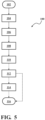
- a method 100 of sealing a component assembly 10, such as an assembly that is part of an aircraft wing 16 having an aircraft wing skin and an aircraft wing spar and defining an internal fuel reservoir 18, is shown in FIG. 5 and described below with reference to the structure shown in FIGS. 1-4 .
- Method 100 commences in frame 102 with providing the first component 12. Following frame 102, the method advances to frame 104. In frame 104, the method includes applying onto the first component 12 the first sealant bead 20. As described above, the first sealant bead 20, in a cross-sectional view, has the first width 20-1 and the first height 20-2, with the magnitude of the first width being greater than the magnitude of the first height.
- the first and second sealant bead 20, 22 may be formed from a common polymeric material, such as polysulfide. Also, the magnitude of the second sealant bead's width (the second width 22-1), as well as the proportion of the dimensions of the first and second sealant beads 20, 22 may be directly proportional to the viscosity of the sealant material. From frame 104, the method moves on to frame 106. In frame 106, the method includes applying over the first sealant bead 20 a second sealant bead 22 having, in the cross-sectional view, the second width 22-1 and the second height 22-2, and thereby generating the sealant stack 24. As described above relative to FIGS. 3 and 4 , the sealant stack 24 applied to the first component 12 generates the component subassembly 10'. As described above, the second height 22-2 is equal to or smaller than the second width 22-1 and is smaller than the first width 20-1.
- the method proceeds to frame 108.
- the method includes arranging over the generated sealant stack 24 the second component 14, such that the sealant stack is positioned between the first outer surface 12A and the second outer surface 14A.
- the method proceeds to frame 110.
- the method includes fastening the second component 14 to the first component 12 with the sealant stack 24 squeezed therebetween.
- the sealant stack 24 provides fluid-tight sealing of the component assembly 10 via rheological flow of the first and second sealant beads 20, 22.
- the resultant irregular gap 34 would be reliably filled between the first and second components 12, 14 by the squeezed sealant.
- fastening the second component 14 to the first component 12 may include installing and tightening the first row 28' of fasteners on one side and the second row 30'of fasteners on the opposite side of the first sealant bead 20.
- the method may advance to frame 112.
- the method includes cleaning up sealant material that may have been squeezed out of the fay-sealed interface 10A and, for example, from individual locations in the irregular gap 34.
- the method may advance to frame 114 for completion of the component assembly 10.
- the method may proceed to frame 116 for incorporation of the component assembly 10 into a greater assembly, such as the aircraft wing 16.
- method 100 is intended to generate a fluid-tight component assembly via two proportionately dissimilar stacked sealant beads, i.e., the sealant bead 22 applied over the first sealant bead 20, to generate the sealant stack 24.
- Such a fluid-tight interface is specifically formed via rheological flow of the first and sealant beads 20, 22.
- the above fluid-tight interface may be especially beneficial in constructing an aircraft wing having a joined aircraft wing spar and wing skin and configured to define a fuel reservoir. While the scope of protection is determined by the appended claims, realizations of the present disclosure can be made in various ways, including those according to the following Clauses.
Landscapes
- Engineering & Computer Science (AREA)
- Mechanical Engineering (AREA)
- Aviation & Aerospace Engineering (AREA)
- General Engineering & Computer Science (AREA)
- Manufacturing & Machinery (AREA)
- Transportation (AREA)
- Gasket Seals (AREA)
Abstract
Description
- The present disclosure relates to an optimized fluid-tight sealing process, such as for an interface between adjacent components.
- A sealing process typically includes application of a sealing substance (sealant) to block the passage of fluids, dust, sound, and heat through openings in materials. Sealing of an assembly typically creates a mechanical closure at an interface between adjacent components or substrates. Sealants may be weak or strong, flexible or rigid, temporary or permanent. Although most sealants are technically not adhesives, some sealants have adhesive or structural qualities.
- Sealants may have electrical isolation or conduction properties and may provide thermal and/or acoustical insulation. Sealants may also be used for simple smoothing of surface transitions or filling of gaps between two or more components. Sealants are often called upon to perform several such functions at once. While sealants typically do not possess great strength, they may be particularly effective in waterproofing assemblies by keeping moisture inside or outside the components or assemblies in which they are used.
- As a sealant fills a gap between components, it forms a barrier as a result of the sealant's physical properties and by its adhesion to adjacent components. Once applied, a sealant is intended to maintain adhesion and its sealing properties for a requisite timeframe when subjected to expected service and environmental conditions. To achieve requisite performance properties, sealant formulations and application processes are carefully developed.
- A method of sealing a component assembly includes providing a first component having a first outer surface. The method also includes applying onto the first component a first sealant bead having, in a cross-sectional view, a first width and a first height. The first width is greater than the first height. The method additionally includes applying over the first sealant bead a second sealant bead having, in the cross-sectional view, a second width and a second height, thereby generating a sealant stack. The second width is equal to or smaller than the second height and the second width is smaller than the first width. The method also includes arranging over the generated sealant stack a second component having a second outer surface, such that the sealant stack is positioned between the first outer surface and the second outer surface. Furthermore, the method includes fastening the second component to the first component with the sealant stack squeezed therebetween. The resultant component assembly is fluid-tight sealed via rheological flow of the first and second sealant beads when the second component is fastened to the first component.
- The first height may be equal to or smaller than the second height.
- The first sealant bead and the second sealant bead may be formed from a common polymeric material.
- The second width may be directly proportional to viscosity of the polymeric material.
- Specifically, the subject polymeric material may be polysulfide.
- At least one of the first and second outer surfaces may be characterized by an uneven profile, thereby generating an irregular gap between the first and second components. The sealant stack may then be arranged in the irregular gap, and the second sealant bead may facilitate filling the irregular gap generated by the uneven profile to seal the component assembly.
- Fastening the second component to the first component may include installing, in the cross-sectional view, and tightening a first fastener on one side of the first sealant bead and a second fastener on an opposite side of the first sealant bead.
- The fluid-tight sealing of the component assembly may be characterized by an absence of redundant fillet and fairing seals between the first and second components.
- The component assembly may be part of an aircraft wing defining a fuel reservoir.
- The first component may be either an aircraft wing skin or an aircraft wing spar and the second component may then be the other aircraft wing part.
- A fay-sealed component assembly employing the above-disclosed sealant stack squeezed between the first and second components to seal an irregular gap therebetween is also disclosed.
- The above features and advantages, and other features and advantages of the present disclosure, will be readily apparent from the following detailed description of the embodiment(s) and best mode(s) for carrying out the described disclosure when taken in connection with the accompanying drawings and appended claims.
-
-
FIG. 1 is a schematic perspective view of fay-sealed component assembly, specifically depicted as part of an aircraft wing with one of the components shown as an aircraft wing skin and the other component shown as an aircraft wing spar, according to the present disclosure. -
FIG. 2 is a schematic close-up cross-sectional front view of the component assembly shown inFIG. 1 , depicting a sealant stack including two sealant beads having dissimilar dimensions arranged in the interface between the assembly components, according to the disclosure. -
FIG. 3 is a schematic close-up cross-sectional front view of the component assembly shown inFIG. 1 , depicting two rows of fasteners arranged on opposite sides of and compressing the sealant stack, according to the disclosure. -
FIG. 4 is a schematic close-up cross-sectional side view of the component assembly shown inFIG. 1 , depicting the sealant stack arranged in an irregular gap between the first and second components as a result of one of the components having an outer surface with an uneven profile, according to the disclosure. -
FIG. 5 illustrates a flowchart for a method of sealing the component assembly shown inFIGS. 1-4 . - Embodiments of the present disclosure as described herein are intended to serve as examples. Other embodiments may take various and alternative forms. Additionally, the drawings are generally schematic and not necessarily to scale. Some features may be exaggerated or minimized to show details of particular components. Therefore, specific structural and functional details disclosed herein are not to be interpreted as limiting, but merely as a representative basis for teaching one skilled in the art to variously employ the present disclosure.
- Certain terminology may be used in the following description for the purpose of reference only, and thus are not intended to be limiting. For example, terms such as "above" and "below" refer to directions in the drawings to which reference is made. Terms such as "front", "back", "fore", "aft", "left", "right", "rear", "side", "upward", "downward", "top", and "bottom", etc., describe the orientation and/or location of portions of the components or elements within a consistent but arbitrary frame of reference, which is made clear by reference to the text and the associated drawings describing the components or elements under discussion.
- Furthermore, terms such as "first", "second", "third", and so on may be used to describe separate components. Such terminology may include the words specifically mentioned above, derivatives thereof, and words of similar import, and are used descriptively for the figures, and do not represent limitations on the scope of the disclosure, as defined by the appended claims. Moreover, the teachings may be described herein in terms of functional and/or logical block components and/or various processing steps. It should be realized that such block components may include a number of hardware, software, and/or firmware components configured to perform the specified functions.
- Referring to the drawings, wherein like reference numbers refer to like components,
FIG. 1 shows anassembly 10 having adjacent components - afirst component 12, and asecond component 14. Theassembly 10 includes a fay-sealed joint orinterface 10A (shown inFIG. 2 ) betweencomponents interface 10A may be configured as a fluid-tight seal, as will be described in detail below. Generally, thefirst component 12 and thesecond component 14 are fastened and fixed to each other, such as via appropriate fasteners, for example, bolts, rivets, etc., or being clamped via appropriate means to generate a robust assembly. Although not limited to the specific example shown inFIG. 1 , thecomponent assembly 10 may be part of anaircraft wing 16 defining aninternal fuel reservoir 18. As further shown in the embodiment ofFIG. 1 , thefirst component 12 may be an aircraft wing skin while thesecond component 14 may be an aircraft wing spar (shown with a flanged configuration), or vice versa. - As shown in
FIG. 2 , thefirst component 12 may be a bottom component and includes a first or topouter surface 12A (shown inFIG. 3 ). Thecomponent assembly 10 also includes afirst sealant bead 20 applied onto thefirst component 12, specifically to the firstouter surface 12A. As may be seen in a cross-sectional view shown inFIG. 3 , thefirst sealant bead 20 is defined by a first width 20-1 and a first height 20-2. The magnitude of the first width 20-1 is greater than the magnitude of the first height 20-2. Thefirst component 12 also includes asecond sealant bead 22 applied over or on top of thefirst sealant bead 20. In the cross-sectional view shown inFIG. 3 , thesecond sealant bead 22 is defined by a second width 22-1 and a second height 22-2. As shown inFIG. 3 , thesecond sealant bead 22 applied over thefirst sealant bead 20 generates asealant stack 24. Thefirst component 12 with thesealant stack 24 arranged thereon constitutes a component subassembly 10' (shown inFIGS. 3 and 4 ) in advance of fastening thesecond component 14 thereto and thereby generating thefinal assembly 10. - With reference to the
sealant stack 24 shown inFIG. 3 , the magnitude of the second height 22-2 is equal to or smaller (i.e., no greater) than the magnitude of second width 22-1. Additionally, the second width 22-1 is smaller than the first width 20-1. Furthermore, the magnitude of first height 20-2 may be equal to or smaller than the magnitude of the second height 22-2. Thefirst sealant bead 20 and thesecond sealant bead 22 may be formed from a common polymeric material, such as polysulfide, to withstand prolonged immersion in a liquid, such as aircraft fuel. The magnitude of the second width 22-1 may be directly proportional to the viscosity of the selected bead material. Additionally, the proportion of dimensions, i.e., the respective widths and heights, of the first andsecond sealant beads sealant beads interface 10A betweencomponents - As shown, the
second component 14 may be arranged as a top component and includes a second or bottomouter surface 14A. In thecomponent assembly 10, thesealant stack 24 is positioned between the firstouter surface 12A and the secondouter surface 14A. A fluid-tight seal 26 (shown inFIG. 2 ) is generated in thecomponent assembly 10 as thesecond component 14 is fastened to thefirst component 12 with thesealant stack 24 squeezed therebetween. As the first andsecond components first sealant bead 20, may be squeezed out of theinterface 10A. - Generally, sealant material is a shear-thickening rheological fluid, i.e., the sealant increases in viscosity with the rate of shear strain. In other words, the sealant material becomes more viscous and less compressible as it is subjected to a load inside a component assembly interface. In the event sealant is trapped between adjacent components, a hydrolock condition may occur, thereby distorting or pillowing the component structure. To avoid hydrolocking and distortion of the component structure in the joint, width 22-1 of the
second sealant bead 22 is smaller than width 20-1 of thefirst sealant bead 20, while the height 22-2 is greater than the first height 20-2. Also, the width 20-1 of thefirst sealant bead 20 is greater than its height 20-2. The subject relative dimensions of thesealant beads sealant stack 24 may be greater than the maximum height of the gap in theinterface 10A to permit reliable filling of the gap. - The
component assembly 10 is thus sealed via rheological flow of the first andsecond sealant beads FIG. 3 , thesecond component 14 may be fastened to thefirst component 12 via afirst fastener 28 on one side (shown as the left side) 24-1 of thesealant stack 24 and asecond fastener 30 on an opposite side (shown as the right side) 24-2 of the sealant stack. Moreover, in thecomponent assembly 10 side or top view along a longitudinal axis X (shown inFIG. 2 ), thefirst fastener 28 may be one of a first row 28'of fasteners and thesecond fastener 30 may be one of a second row 30' of fasteners arranged along the stackedsealant beads tight seal 26 assembly. - As shown in
FIG. 4 , at least one of the first and secondouter surfaces uneven profile 32, either in the cross-sectional view or along the longitudinal axis X. Such anuneven profile 32 of either of the first and secondouter surfaces inconsistent gap 34 between the first andsecond components interface 10A. The fluid-tight seal 26 may be maintained despite theirregular gap 34 via the described configuration of thesealant stack 24 arranged in therein, specifically because of the rheological flow of the first andsealant beads tight seal 26 ofcomponent assembly 10 may be maintained even in the absence of redundant fillet and fairing seals, which are common in the art, between the first andsecond components component assembly 10 may be configured as an un-faired and un-filleted fay-sealed assembly. - The magnitude of
irregular gap 34 may be used to determine ranges of the first and second sealant bead heights 20-2, 22-2. Nominal gap thickness may be generally taken up by thefirst sealant bead 20, while gap variation and surface irregularities may be taken up by thesecond sealant bead 22. For example, the first sealant bead height 20-2 may be equal to the average gap thickness. The second sealant bead height 22-2 may be equal to the maximum possible gap thickness anywhere in the joint. Ratios between widths and heights of the first andsecond sealant beads second sealant bead 22 relative to its width 22-1 and a tallerfirst sealant bead 20 relative to its width 20-1. Also, in such an embodiment, the width 22-1 of thesecond sealant bead 22 may be closer to 1:1 ratio relative to the magnitude of its height 22-2. - The
sealant stack 24 may be instrumental in facilitating rheological flow of thefirst sealant bead 20 into the wider spaces within theirregular gap 34 and controlled squeezing of the first sealant bead out of the narrower spaces. Meanwhile, thesecond sealant bead 22 is instrumental in filling the general space along the longitudinal axis X between the first andsecond components sealant stack 24 is arranged in theirregular gap 34, thefirst sealant bead 20 would fill the majority of theinterface 10A. Thesecond sealant bead 22 would then flow into adjacent gap irregularities and facilitate filling theirregular gap 34 generated by theuneven profile 32. The first andsecond sealant beads component assembly 10 as thesealant stack 24 is squeezed during fastening without generating sealant hydrolocking and/or distortion of interfacing components. Accordingly, the squeezing of thesealant stack 24 is intended to fully seal theinterface 10A and deliver reliable leak-free performance of thecomponent assembly 10. - A
method 100 of sealing acomponent assembly 10, such as an assembly that is part of anaircraft wing 16 having an aircraft wing skin and an aircraft wing spar and defining aninternal fuel reservoir 18, is shown inFIG. 5 and described below with reference to the structure shown inFIGS. 1-4 .Method 100 commences inframe 102 with providing thefirst component 12. Followingframe 102, the method advances to frame 104. Inframe 104, the method includes applying onto thefirst component 12 thefirst sealant bead 20. As described above, thefirst sealant bead 20, in a cross-sectional view, has the first width 20-1 and the first height 20-2, with the magnitude of the first width being greater than the magnitude of the first height. - As described above with respect to
FIGS. 1-4 , the first andsecond sealant bead second sealant beads frame 104, the method moves on to frame 106. Inframe 106, the method includes applying over the first sealant bead 20 asecond sealant bead 22 having, in the cross-sectional view, the second width 22-1 and the second height 22-2, and thereby generating thesealant stack 24. As described above relative toFIGS. 3 and 4 , thesealant stack 24 applied to thefirst component 12 generates the component subassembly 10'. As described above, the second height 22-2 is equal to or smaller than the second width 22-1 and is smaller than the first width 20-1. - After
frame 106, the method proceeds to frame 108. Inframe 108, the method includes arranging over the generatedsealant stack 24 thesecond component 14, such that the sealant stack is positioned between the firstouter surface 12A and the secondouter surface 14A. Afterframe 108, the method proceeds to frame 110. Inframe 110, the method includes fastening thesecond component 14 to thefirst component 12 with thesealant stack 24 squeezed therebetween. Thus squeezed, thesealant stack 24 provides fluid-tight sealing of thecomponent assembly 10 via rheological flow of the first andsecond sealant beads outer surfaces uneven profile 32, the resultantirregular gap 34 would be reliably filled between the first andsecond components FIGS. 1-4 , fastening thesecond component 14 to thefirst component 12 may include installing and tightening the first row 28' of fasteners on one side and the second row 30'of fasteners on the opposite side of thefirst sealant bead 20. - From
frame 110, the method may advance to frame 112. Inframe 112, the method includes cleaning up sealant material that may have been squeezed out of the fay-sealedinterface 10A and, for example, from individual locations in theirregular gap 34. Afterframe 112, the method may advance to frame 114 for completion of thecomponent assembly 10. Following either of theframes component assembly 10 into a greater assembly, such as theaircraft wing 16. Overall,method 100 is intended to generate a fluid-tight component assembly via two proportionately dissimilar stacked sealant beads, i.e., thesealant bead 22 applied over thefirst sealant bead 20, to generate thesealant stack 24. Such a fluid-tight interface is specifically formed via rheological flow of the first andsealant beads
While the scope of protection is determined by the appended claims, realizations of the present disclosure can be made in various ways, including those according to the following Clauses. - Clause 1 - A method (100) of sealing a component assembly (10), comprising:
- providing a first component (12) having a first outer surface (12A);
- applying onto the first component a first sealant bead (20) having, in a cross-sectional view, a first width (20-1) and a first height (20-2), wherein the first width is greater than the first height;
- applying over the first sealant bead a second sealant bead (22) having, in the cross-sectional view, a second width (22-1) and a second height (22-2), thereby generating a sealant stack (24), wherein:
- the second height is equal to or smaller than the second width; and
- the second width is smaller than the first width;
- arranging over the generated sealant stack a second component (14) having a second outer surface (14A), such that the sealant stack is positioned between the first outer surface and the second outer surface; and
- fastening the second component to the first component with the sealant stack squeezed therebetween and thereby providing fluid-tight sealing of the component assembly via rheological flow of the first and second sealant beads.
- Clause 2 - The method of Clause 1, wherein the first height is equal to or smaller than the second height.
- Clause 3 - The method of Clause 1, wherein the first sealant bead and the second sealant bead are formed from a common polymeric material.
- Clause 4 - The method of Clause 3, wherein the second width is directly proportional to viscosity of the polymeric material.
- Clause 5 - The method of Clause 3, wherein the polymeric material is polysulfide.
- Clause 6 - The method of Clause 1, wherein:
- at least one of the first and second outer surfaces is characterized by an uneven profile (32) thereby generating an irregular gap (34) between the first and second components;
- the sealant stack is arranged in the irregular gap; and
- the second sealant bead facilitates filling the irregular gap to seal the component assembly.
- Clause 7 - The method of Clause 1, wherein fastening the second component to the first component includes installing, in the cross-sectional view, and tightening a first fastener (28) on one side of the first sealant bead and a second fastener (30) on an opposite side of the first sealant bead.
- Clause 8 - The method of Clause 1, wherein the fluid-tight sealing of the component assembly is characterized by an absence of redundant fillet and fairing seals between the first and second components.
- Clause 9 - The method of Clause 1, wherein part of an aircraft wing (16) defining a fuel reservoir (18).
- Clause 10 - The method of Clause 9, wherein the first component is one of an aircraft wing skin and an aircraft wing spar and the second component is the other of the aircraft wing skin and the aircraft wing spar.
- Clause 11 - A fay-sealed component assembly (10), comprising:
- a first component (12) having a first outer surface (12A);
- a first sealant bead (20) applied onto the first component;
- a second sealant bead (22) applied over the first sealant bead, wherein the second sealant bead applied over the first sealant bead generates a sealant stack (24);
- a second component (14) arranged over the sealant stack, wherein the second component includes a second outer surface (14A), such that the sealant stack is positioned between the first outer surface and the second outer surface;
- at least one of the first and second outer surfaces is characterized by an uneven profile (32); and
- the second component is fastened to the first component with the sealant stack squeezed therebetween to thereby fluid-tight seal the component assembly via rheological flow of the first and second sealant beads.
- Clause 12 - The fay-sealed component assembly of Clause 11, wherein the first sealant bead and the second sealant bead are formed from a common polymeric material.
- Clause 13 - The fay-sealed component assembly of
Clause 12, wherein a width (22-1) of the second sealant bead is directly proportional to viscosity of the polymeric material. - Clause 14 - The fay-sealed component assembly of
Clause 12, wherein the polymeric material is polysulfide. - Clause 15 - The fay-sealed component assembly of Clause 11, wherein:
- the uneven profile of the at least one of the first and second outer surfaces generates an irregular gap (34) between the first and second components;
- the sealant stack is arranged in the irregular gap; and
- the second sealant bead facilitates filling the irregular gap to seal the component assembly.
- Clause 16 - The fay-sealed component assembly of Clause 11, wherein, in a cross-sectional view of the sealant stack, the second component is fastened to the first component via a first fastener (28) on one side of the first sealant bead and a second fastener (30) on an opposite side of the first sealant bead.
- Clause 17 - The fay-sealed component assembly of Clause 11, wherein the fluid-tight sealed component assembly is characterized by an absence of redundant fillet and fairing seals between the first and second components.
- Clause 18 - The fay-sealed component assembly of Clause 11, wherein the component assembly is part of an aircraft wing (16) defining a fuel reservoir (18), and wherein the first component is one of an aircraft wing skin and an aircraft wing spar and the second component is the other of the aircraft wing skin and the aircraft wing spar.
- Clause 19 - A method (100) of sealing an aircraft wing (16) assembly defining a fuel reservoir (18), comprising:
- providing an aircraft wing skin (12) having a first outer surface (12A);
- applying onto the aircraft wing skin a first sealant bead (20) having, in a cross-sectional view, a first width (20-1) and a first height (20-2), wherein the first width is greater than the first height;
- applying over the first sealant bead a second sealant bead (22) having, in the cross-sectional view, a second width (22-1) and a second height (22-2), thereby generating a sealant stack (24), wherein:
- the second height is equal to or smaller than the second width; and
- the second width is smaller than the first width;
- arranging over the generated sealant stack an aircraft wing spar (14) having a second outer surface (14A), such that the sealant stack is positioned between the first outer surface and the second outer surface; and
- fastening the aircraft wing spar to the aircraft wing skin with the sealant stack squeezed therebetween and thereby providing fluid-tight sealing of the aircraft wing assembly via rheological flow of the first and second sealant beads, wherein fastening the aircraft wing spar to the aircraft wing skin includes installing, in the cross-sectional view, and tightening a first fastener (28) on one side of the first sealant bead and a second fastener (30) on an opposite side of the first sealant bead.
- Clause 20 - A component subassembly (10'), comprising:
- a first component (12) having a first outer surface (12A);
- a first sealant bead (20) applied onto the first component, wherein, in a cross-sectional view, the first sealant bead is defined by a first width (20-1) and a first height (20-2), and wherein the first width is greater than the first height;
- a second sealant bead (22) applied over the first sealant bead thereby generating a sealant stack (24), wherein:
- in the cross-sectional view, the second sealant bead is defined by a second width (22-1) and a second height (22-2);
- the second height is equal to or smaller than the second width; and
- the second width is smaller than the first width; and
- a second component (14) arranged relative to the sealant stack and having a second outer surface (14A) and configured to be fastened to the first component with the sealant stack squeezed between the first outer surface and the second outer surface, such that a fluid-tight fay seal is generated between the first and second components via rheological flow of the first and second sealant beads.
- Clause 21 - The component subassembly of
Clause 20, wherein the first height is equal to or smaller than the second height. - Clause 22 - The component subassembly of
Clause 20, wherein the first sealant bead and the second sealant bead are formed from a common polymeric material. - Clause 23 - The component subassembly of
Clause 22, wherein the second width is directly proportional to viscosity of the polymeric material. - Clause 24 - The component subassembly of
Clause 22, wherein the polymeric material is polysulfide. - The detailed description and the drawings or figures are supportive and descriptive of the disclosure, but the scope of the disclosure is defined solely by the claims. While some of the best modes and other embodiments for carrying out the claimed disclosure have been described in detail, various alternative designs and embodiments exist for practicing the disclosure defined in the appended claims. Furthermore, the embodiments shown in the drawings, or the characteristics of various embodiments mentioned in the present description are not necessarily to be understood as embodiments independent of each other. Rather, it is possible that each of the characteristics described in one of the examples of an embodiment may be combined with one or a plurality of other desired characteristics from other embodiments, resulting in other embodiments not described in words or by reference to the drawings. Accordingly, such other embodiments fall within the framework of the scope of the appended claims.
Claims (15)
- A method (100) of sealing a component assembly (10), comprising:providing a first component (12) having a first outer surface (12A);
applying onto the first component a first sealant bead (20) having, in a cross-sectional view, a first width (20-1) and a first height (20-2), wherein the first width is greater than the first height;applying over the first sealant bead a second sealant bead (22) having, in the cross-sectional view, a second width (22-1) and a second height (22-2), thereby generating a sealant stack (24), wherein:the second height (22-2) is equal to or smaller than the second width (22-1); andthe second width (22-1) is smaller than the first width (20-1);arranging over the generated sealant stack a second component (14) having a second outer surface (14A), such that the sealant stack is positioned between the first outer surface (12A) and the second outer surface (14A); andfastening the second component (14) to the first component (12) with the sealant stack squeezed therebetween and thereby providing fluid-tight sealing of the component assembly via rheological flow of the first and second sealant beads (20, 22). - The method of claim 1, wherein the first height (20-2) is equal to or smaller than the second height (22-2).
- The method of claim 1 or 2, wherein the first sealant bead (20) and the second sealant bead (22) are formed from a common polymeric material, preferably polysulfide, and optionally wherein the second width (22-1) is directly proportional to viscosity of the polymeric material.
- The method of any one of claims 1 to 3, wherein:at least one of the first and second outer surfaces (12A, 14A) is characterized by an uneven profile (32) thereby generating an irregular gap (34) between the first and second components (12, 14);the sealant stack (24) is arranged in the irregular gap (34); andthe second sealant bead (22) facilitates filling the irregular gap (34) to seal the component assembly (10).
- The method of any one of claims 1 to 4, wherein fastening the second component (14) to the first component (12) includes installing, in the cross-sectional view, and tightening a first fastener (28) on one side of the first sealant bead (20) and a second fastener (30) on an opposite side of the first sealant bead (22).
- The method of any one of claims 1 to 5, wherein the fluid-tight sealing of the component assembly (10) is characterized by an absence of redundant fillet and fairing seals between the first and second components (12, 14).
- The method of any one of claims 1 to 6, wherein the component assembly (10) is part of an aircraft wing (16) defining a fuel reservoir (18).
- The method of claim 7, wherein the first component (12) is one of an aircraft wing skin and an aircraft wing spar and the second component (14) is the other of the aircraft wing skin and the aircraft wing spar.
- A component subassembly (10'), comprising:a first component (12) having a first outer surface (12A);a first sealant bead (20) applied onto the first component, wherein, in a cross-sectional view, the first sealant bead is defined by a first width (20-1) and a first height (20-2), and wherein the first width is greater than the first height;a second sealant bead (22) applied over the first sealant bead thereby generating a sealant stack (24), wherein:in the cross-sectional view, the second sealant bead is defined by a second width (22-1) and a second height (22-2);the second height (22-2) is equal to or smaller than the second width (22-1); andthe second width (22-1) is smaller than the first width (20-1); anda second component (14) arranged relative to the sealant stack (24) and having a second outer surface (14A) and configured to be fastened to the first component with the sealant stack squeezed between the first outer surface and the second outer surface, such that a fluid-tight fay seal is generated between the first and second components (12, 14) via rheological flow of the first and second sealant beads (20, 22).
- The component subassembly of claim 9, wherein the first height (20-2) is equal to or smaller than the second height (22-2).
- The component subassembly of claim 9 or 10, wherein the first sealant bead (20) and the second sealant bead (22) are formed from a common polymeric material, preferably polysulfide, and optionally wherein the second width (22-1) is directly proportional to viscosity of the polymeric material.
- A fay-sealed component assembly (10), comprising a component subassembly (10') according to any one of claims 9 to 11, wherein:at least one of the first and second outer surfaces (12A, 14A) is characterized by an uneven profile (32); andthe second component (14) is fastened to the first component (12) with the sealant stack (24) squeezed therebetween to thereby fluid-tight seal the component assembly (10) via rheological flow of the first and second sealant beads, and optionally wherein:the uneven profile of the at least one of the first and second outer surfaces (12A, 14A) generates an irregular gap (34) between the first and second components;the sealant stack is arranged in the irregular gap (34); andthe second sealant bead (22) facilitates filling the irregular gap (34) to seal the component assembly.
- The fay-sealed component assembly of claim 12, wherein, in a cross-sectional view of the sealant stack, the second component is fastened to the first component via a first fastener (28) on one side of the first sealant bead (20) and a second fastener (30) on an opposite side of the first sealant bead (20).
- The fay-sealed component assembly of claim 12 or 13, wherein the fluid-tight sealed component assembly is characterized by an absence of redundant fillet and fairing seals between the first and second components.
- The fay-sealed component assembly of any one of claims 12 to 14, wherein the component assembly is part of an aircraft wing (16) defining a fuel reservoir (18), and wherein the first component is one of an aircraft wing skin and an aircraft wing spar and the second component is the other of the aircraft wing skin and the aircraft wing spar.
Applications Claiming Priority (1)
| Application Number | Priority Date | Filing Date | Title |
|---|---|---|---|
| US18/540,620 US12534182B2 (en) | 2023-12-14 | 2023-12-14 | Optimized sealing process |
Publications (1)
| Publication Number | Publication Date |
|---|---|
| EP4571128A1 true EP4571128A1 (en) | 2025-06-18 |
Family
ID=93742005
Family Applications (1)
| Application Number | Title | Priority Date | Filing Date |
|---|---|---|---|
| EP24216197.4A Pending EP4571128A1 (en) | 2023-12-14 | 2024-11-28 | Optimized sealing process |
Country Status (4)
| Country | Link |
|---|---|
| US (1) | US12534182B2 (en) |
| EP (1) | EP4571128A1 (en) |
| JP (1) | JP2025102691A (en) |
| CN (1) | CN120159929A (en) |
Families Citing this family (1)
| Publication number | Priority date | Publication date | Assignee | Title |
|---|---|---|---|---|
| US20260078823A1 (en) * | 2024-09-18 | 2026-03-19 | The Boeing Company | Molded seal boots, sealed structures, and methods for sealing |
Citations (2)
| Publication number | Priority date | Publication date | Assignee | Title |
|---|---|---|---|---|
| US11543029B2 (en) * | 2020-02-25 | 2023-01-03 | The Boeing Company | Part edge seal arrangement and joining method |
| US20230081133A1 (en) * | 2021-09-13 | 2023-03-16 | The Boeing Company | Aircraft fuel tank joints and methods of assembling the same |
Family Cites Families (9)
| Publication number | Priority date | Publication date | Assignee | Title |
|---|---|---|---|---|
| US4625979A (en) * | 1985-08-05 | 1986-12-02 | Felt Products Mfg. Co. | Seal assembly having a low extrusion resistant elastomeric sealing bead |
| DE8800475U1 (en) * | 1988-01-16 | 1988-02-25 | Reinz Dichtungs-Gesellschaft Mbh, 7910 Neu-Ulm | Flat seal |
| DE4319965C3 (en) * | 1993-06-14 | 2000-09-14 | Emi Tec Elektronische Material | Method of manufacturing an electromagnetic shielding case |
| US5615898A (en) * | 1995-08-15 | 1997-04-01 | Clark; James M. | Bead seal motorcycle gasket |
| US5869814A (en) * | 1996-07-29 | 1999-02-09 | The Boeing Company | Post-weld annealing of thermoplastic welds |
| US6073938A (en) * | 1997-11-06 | 2000-06-13 | Kokusan Parts Industry Co., Ltd. | Sealing structure |
| US20120276362A1 (en) * | 2011-04-28 | 2012-11-01 | Sikorsky Aircraft Corporation | Fay surface sealant application |
| US11780557B2 (en) * | 2020-04-08 | 2023-10-10 | The Boeing Company | System and method for forming a seal between structural components |
| EP4074494A1 (en) * | 2021-04-12 | 2022-10-19 | The Boeing Company | Methods of forming uncured sealant assemblies and using such assemblies for sealing and bonding parts |
-
2023
- 2023-12-14 US US18/540,620 patent/US12534182B2/en active Active
-
2024
- 2024-10-08 CN CN202411390437.0A patent/CN120159929A/en active Pending
- 2024-11-28 EP EP24216197.4A patent/EP4571128A1/en active Pending
- 2024-12-05 JP JP2024212037A patent/JP2025102691A/en active Pending
Patent Citations (2)
| Publication number | Priority date | Publication date | Assignee | Title |
|---|---|---|---|---|
| US11543029B2 (en) * | 2020-02-25 | 2023-01-03 | The Boeing Company | Part edge seal arrangement and joining method |
| US20230081133A1 (en) * | 2021-09-13 | 2023-03-16 | The Boeing Company | Aircraft fuel tank joints and methods of assembling the same |
Also Published As
| Publication number | Publication date |
|---|---|
| US20250196994A1 (en) | 2025-06-19 |
| CN120159929A (en) | 2025-06-17 |
| JP2025102691A (en) | 2025-07-08 |
| US12534182B2 (en) | 2026-01-27 |
Similar Documents
| Publication | Publication Date | Title |
|---|---|---|
| US12534182B2 (en) | Optimized sealing process | |
| DE60208096T2 (en) | Flat gasket for sealing a T-area forming sealing area | |
| US8056302B2 (en) | Door panel | |
| GB2401085A (en) | Vehicle body construction | |
| US20190145094A1 (en) | Sealing strip for sealing joints between elements, and method for producing a sealing strip | |
| JPS63210464A (en) | Laminated metal gasket | |
| CN214170682U (en) | Cylinder head and vehicle | |
| CN216081145U (en) | Sealing gasket structure of plate heat exchanger | |
| JPH06305329A (en) | Method for forming hemming part of automobile body | |
| CN212485559U (en) | Sealing structure for butt joint edge rib of antenna housing unit plate | |
| JP2000193093A (en) | Seal structure of three-member joint | |
| JPS597276Y2 (en) | Seal material for assembled panel aquarium | |
| US2814841A (en) | Sealing strip | |
| CN220225756U (en) | Wedge-shaped sealing strip for sealing beam and column and sealing device comprising same | |
| US20230081133A1 (en) | Aircraft fuel tank joints and methods of assembling the same | |
| CN217680202U (en) | Panel of assembled fitment construction | |
| US12215536B2 (en) | Mulling system for plural fenestration assemblies with joining plates and deflectable seal member therebetween | |
| CN223583125U (en) | A side beam structure for a battery box and the battery box thereof. | |
| JP3016268B2 (en) | Exterior wall panel joint structure | |
| CN211647814U (en) | Composite adhesive tape for window | |
| US20240076929A1 (en) | Mulling system for plural fenestration assemblies with matching thermally broken joining plates that have rotated and engaged arrangement across mulling axis | |
| JP2548664Y2 (en) | Stacked metal laminated gasket | |
| US11988286B2 (en) | Seal structure | |
| CN214534981U (en) | Metal gasket and flange assembly | |
| CN215722458U (en) | High-strength PP (polypropylene) plate |
Legal Events
| Date | Code | Title | Description |
|---|---|---|---|
| PUAI | Public reference made under article 153(3) epc to a published international application that has entered the european phase |
Free format text: ORIGINAL CODE: 0009012 |
|
| STAA | Information on the status of an ep patent application or granted ep patent |
Free format text: STATUS: THE APPLICATION HAS BEEN PUBLISHED |
|
| AK | Designated contracting states |
Kind code of ref document: A1 Designated state(s): AL AT BE BG CH CY CZ DE DK EE ES FI FR GB GR HR HU IE IS IT LI LT LU LV MC ME MK MT NL NO PL PT RO RS SE SI SK SM TR |
|
| STAA | Information on the status of an ep patent application or granted ep patent |
Free format text: STATUS: REQUEST FOR EXAMINATION WAS MADE |
|
| 17P | Request for examination filed |
Effective date: 20251119 |
|
| GRAP | Despatch of communication of intention to grant a patent |
Free format text: ORIGINAL CODE: EPIDOSNIGR1 |
|
| STAA | Information on the status of an ep patent application or granted ep patent |
Free format text: STATUS: GRANT OF PATENT IS INTENDED |
|
| INTG | Intention to grant announced |
Effective date: 20260324 |
|
| RIC1 | Information provided on ipc code assigned before grant |
Ipc: F16B 5/02 20060101AFI20260316BHEP Ipc: B64C 3/34 20060101ALI20260316BHEP Ipc: F16B 5/06 20060101ALN20260316BHEP |