EP4571109A1 - Linear actuator, compressor, pump, and household appliance - Google Patents
Linear actuator, compressor, pump, and household appliance Download PDFInfo
- Publication number
- EP4571109A1 EP4571109A1 EP23216497.0A EP23216497A EP4571109A1 EP 4571109 A1 EP4571109 A1 EP 4571109A1 EP 23216497 A EP23216497 A EP 23216497A EP 4571109 A1 EP4571109 A1 EP 4571109A1
- Authority
- EP
- European Patent Office
- Prior art keywords
- stator
- linear actuator
- magnet component
- yoke
- compressor
- Prior art date
- Legal status (The legal status is an assumption and is not a legal conclusion. Google has not performed a legal analysis and makes no representation as to the accuracy of the status listed.)
- Pending
Links
Images
Classifications
-
- F—MECHANICAL ENGINEERING; LIGHTING; HEATING; WEAPONS; BLASTING
- F04—POSITIVE - DISPLACEMENT MACHINES FOR LIQUIDS; PUMPS FOR LIQUIDS OR ELASTIC FLUIDS
- F04B—POSITIVE-DISPLACEMENT MACHINES FOR LIQUIDS; PUMPS
- F04B35/00—Piston pumps specially adapted for elastic fluids and characterised by the driving means to their working members, or by combination with, or adaptation to, specific driving engines or motors, not otherwise provided for
- F04B35/04—Piston pumps specially adapted for elastic fluids and characterised by the driving means to their working members, or by combination with, or adaptation to, specific driving engines or motors, not otherwise provided for the means being electric
- F04B35/045—Piston pumps specially adapted for elastic fluids and characterised by the driving means to their working members, or by combination with, or adaptation to, specific driving engines or motors, not otherwise provided for the means being electric using solenoids
Definitions
- the present invention concerns a linear actuator, a compressor comprising such linear actuator, a pump comprising such linear actuator, and a household appliance including such compressor and/or pump.
- Linear actuators are machine components which produce a usually reciprocating linear motion from energy, in particular from electrical input supplied thereto.
- they may be included in compressors and/or pumps as those integrated in household appliances, for example.
- a linear compressor which comprises a piston configured to linearly reciprocate in a cylinder so as to compress a refrigerant.
- the compressor comprises an inner and an outer stator arranged with an interspace in-between, and a permanent magnet connected to the piston and positioned in the interspace.
- Mutual electromagnetic force between the permanent magnet, the inner stator, and the outer stator causes a linear motion of the permanent magnet and, therewith, of the piston connected thereto.
- US 2020/0395836 A1 discloses a compressor having a linear motor comprising an outer stator, an inner stator, and a mover which is located between the outer and the inner stator and coupled to a piston.
- the outer stator includes a plurality of laminated blocks, on which a coil is wound. Two permanent magnets are coupled to the inner stator.
- a linear actuator according to the present invention comprises a stator, a magnet component, and a yoke.
- the stator includes a plurality of core elements; for instance, the plurality may comprise at least 12 or at least 16 core elements, and/or at most 24 or at most 20 core elements. At least one of the core elements may advantageously be a laminated iron core segment.
- the stator further comprises a solenoid coil which may be wound on a bobbin (preferably made of plastic) and/or which may be at least partially embedded in one or more of the core elements.
- the magnet component of the linear actuator which may comprise at least one permanent (in particular NdFeB) magnet, is arranged spaced apart from the stator. Accordingly, a circumferential air gap is formed between the stator and the magnet component.
- Said components of the linear actuator are arranged to generate an alternating magnetic flux in response to alternately poled electric power input.
- the magnet component is caused to linearly reciprocate relative to the stator.
- a magnetic circuit thus is at least partially formed by the stator, the magnet component, and the yoke providing permeability paths for the magnetic flux.
- the yoke may at least partially be made of iron.
- the yoke is coupled to the magnet component, so that the yoke moves, relative to the stator, when the magnet component does.
- the magnet component may preferably be at least partially arranged between the stator and the yoke.
- a magnet component's surface facing away from the stator may be smaller than a yoke's surface facing the stator (at least partially with the magnet component in-between).
- said magnet component's surface may entirely face said yoke's surface, in particular preferably entirely abutting thereon and/or being joined therewith.
- said magnet component's surface facing away from the stator may be connected to a centre region of said yoke's surface facing the stator.
- the yoke and the magnet component are at least partially arranged in a space encompassed by the stator.
- the plurality of core elements may be arranged, side by side, around said space, thus each being a segment of a wall of said space.
- said space may be rotational symmetric, in particular of finite order or with respect to any angle.
- the reciprocating motion of the magnet component (and the yoke) relative to the stator may be in axial direction.
- the magnet component and/or the yoke may have an annular shape.
- the stator encompasses a rotational symmetric space containing at least a portion of the yoke and the magnet component as mentioned above, the stator, the annular magnet component and the annular yoke may be arranged coaxial to each other, i.e., their respective centre axes may coincide.
- Such embodiments are particularly adapted as linear actuators configured to operate a compressor or pump arranged in their centre space.
- the magnet component may comprise a plurality of permanent (e.g., neodymium) magnet segments which are assembled to form a ring.
- the magnet component may comprise at least one (preferably monolithic, advantageously neodymium) ring magnet (being an annular permanent magnet); the linear actuator according to such embodiments of the present invention advantageously requires a reduced assembling effort when it is manufactured.
- the permanent magnets and/or the magnet ring are preferably oriented radially with respect to a centre axis of the annular magnet component, i.e., the respective north pole faces radially outwards and the south pole faces the centre axis, or vice versa.
- the linear actuator further comprises a piston which may be attached to the yoke, such that the yoke is immobile relative to the piston.
- the linear actuator may further comprise a cylinder component attached to the yoke, such that the yoke is immobile relative to the cylinder component.
- At least one of the core elements comprised by the stator may preferably have a flat surface (i.e., a surface extending along a mathematical plane) facing the magnet component.
- all core elements of the stator may have such surface.
- said space may then be shaped as a (preferably right) prism, the side surfaces of which each being formed by a flat surface of a respective one of such core elements.
- one or more of the core elements may have a flat surface facing away from the magnet component.
- a compressor according to the present invention comprises a linear actuator according to an embodiment of the present invention.
- the linear actuator is preferably configured to vary a volume of a compression chamber formed by the compressor.
- a pump according to the present invention comprises a linear actuator according to an embodiment of the present invention.
- the yoke of the linear actuator comprised by such compressor or pump, respectively, may advantageously be attached to a piston or to a cylinder component as mentioned above.
- the compressor or pump may preferably further comprise a cylinder component which encompasses the piston and which is arranged stationary relative to the stator. Accordingly, in such embodiments, the piston is linearly movable within the cylinder component.
- the compressor or pump may preferably further comprise a piston which is encompassed by the cylinder component and which is arranged stationary relative to the stator. Accordingly, in such embodiments, the cylinder component is linearly movable around the immobile piston arranged therein. Such embodiments facilitate a particularly compact construction of the compressor or pump.
- a household appliance according to the present invention comprises a compressor and/or a pump respectively in accordance with an embodiment of the present invention.
- the household appliance in particular may be a major appliance such as a washing machine, a tumble drier, a dishwater, a refrigerator, or a freezer.
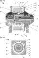
- a compressor 100 according to an embodiment of the present invention is depicted.
- the compressor 100 comprises a linear actuator 1 according to an exemplary embodiment of the present invention, a housing 2, and springs 3a, 3b elastically supporting the linear actuator 1 in the housing 2.
- Figure 1a shows the compressor 100 in a sectional view along a centre axis X of a rotationally symmetric space encompassed by a stator 10 of the linear actuator 1.
- Figure 1b shows a centre portion of the compressor 100 in a sectional view orthogonal to said axis X, namely, along section A-A as indicated in Figure 1a .
- the linear actuator 1 of the compressor 100 comprises a magnet component 20, and a yoke 30 coupled to the magnet component 20.
- Both the magnet component 20 and the yoke 30 have an annular shape, and they are arranged, in said rotationally symmetric space, with their respective centre axis coinciding with said axis X.
- the stator 10, the magnet component 20 and the yoke thus are coaxial to each other.
- the magnet component 20 is configured as a monolithic ring magnet and arranged between the yoke 30 and the stator, from which the magnet component 20 is spaced apart such that a circumferential air gap G surrounding the magnet component 20 is present between the stator 10 and the magnet component 20.
- a yoke's surface F 30 facing the stator 10 is larger than a magnet component's surface F20 facing away from the stator 10, the magnet component's surface F 20 entirely facing the yoke 30 and abutting on a centre region thereof.
- the stator 10 includes a plurality of core elements 11 and a solenoid coil 12 wound on a bobbin 13 and at least partially embedded in the core elements 11.
- the core elements each have a flat surface S a , S b facing the magnet component 20.
- the core elements each have a flat surface F a , F b facing away from the magnet component 20.
- Such core elements 11 can be produced by applying a particularly simple production technology, and thus they reduce time and effort in the manufacturing.
- the rotationally symmetric space encompassed by the stator 10 is shaped as a right prism delimited by the core elements' 11 surfaces S a , S b facing the magnet component 20.
- said circumferential air gap G appearing between the stator 10 and the magnet component 20 has an uneven shape.
- the core elements 11 are of laminated iron (not visible in the figures).
- stator the magnet component, and the yoke form a magnetic circuit. Therefore, in consequence of alternating electric power input, which is realised by connection of the solenoid coil to an electric power source and varying a current direction (not shown in the figures), a magnetic flux is generated which produces a linearly reciprocating motion of the magnet component 20, with the yoke 30 coupled thereto, relative to the stator 10 and in a direction parallel to the axis X mentioned above.
- the motion is indicated by double arrows.
- a cylinder component 40 which accordingly is reciprocated along with the yoke 30 and the magnet component 20.
- the cylinder component 40 contains a piston 4 which is stationary to the housing 2 of the compressor 100; in particular, the piston 4 may be fastened to or at least partially be formed monolithically with the housing 2, e.g., as a protuberance thereof.
- a volume of a compressor space C is varied.
- a gas (not shown in the figures) the compressor space C may contain can be compressed before being conveyed, through respective valves, out of the compressor space C.
- a linear actuator 1 comprising a stator 10 comprising a plurality of core elements 11, 11 a , 11 b , a magnet component 20 spaced apart from the stator, and a yoke 30, which are adapted to generate, in consequence of alternating electric power input, an alternating magnetic flux producing a linearly reciprocating motion of the magnet component 20 relative to the stator 10.
- the yoke 30 is coupled to the magnet component 20.
- a pump and a compressor 100 respectively comprising such linear actuator 1, and a household appliance comprising such pump and/or such compressor.
Landscapes
- Engineering & Computer Science (AREA)
- Mechanical Engineering (AREA)
- General Engineering & Computer Science (AREA)
- Reciprocating, Oscillating Or Vibrating Motors (AREA)
- Compressor (AREA)
- Compressors, Vaccum Pumps And Other Relevant Systems (AREA)
Abstract
Disclosed is a linear actuator 1 comprising a stator 10 comprising a plurality of core elements 11, 11a, 11b, a magnet component 20 spaced apart from the stator, and a yoke 30, which are adapted to generate, in consequence of alternating electric power input, an alternating magnetic flux producing a linearly reciprocating motion of the magnet component 20 relative to the stator 10. Therein, the yoke 30 is coupled to the magnet component 20.
Further disclosed are a pump and a compressor 100 respectively comprising such linear actuator 1, and a household appliance comprising such pump and/or such compressor.
Description
- The present invention concerns a linear actuator, a compressor comprising such linear actuator, a pump comprising such linear actuator, and a household appliance including such compressor and/or pump.
- Linear actuators are machine components which produce a usually reciprocating linear motion from energy, in particular from electrical input supplied thereto. In particular, they may be included in compressors and/or pumps as those integrated in household appliances, for example.
- From
US 2020/0260628 A1 , a linear compressor is known which comprises a piston configured to linearly reciprocate in a cylinder so as to compress a refrigerant. For driving the motion, the compressor comprises an inner and an outer stator arranged with an interspace in-between, and a permanent magnet connected to the piston and positioned in the interspace. Mutual electromagnetic force between the permanent magnet, the inner stator, and the outer stator causes a linear motion of the permanent magnet and, therewith, of the piston connected thereto. -
US 2020/0395836 A1 discloses a compressor having a linear motor comprising an outer stator, an inner stator, and a mover which is located between the outer and the inner stator and coupled to a piston. The outer stator includes a plurality of laminated blocks, on which a coil is wound. Two permanent magnets are coupled to the inner stator. - It is an object of the present invention to provide an improved linear actuator, an improved compressor, an improved pump, and an improved household appliance.
- The object is achieved by a linear actuator according to claim 1, by a compressor according to claim 7, by a pump according to claim 8, and by a household appliance according to claim 9. Advantageous embodiments are disclosed in the dependent claims, the description, and the drawings.
- A linear actuator according to the present invention comprises a stator, a magnet component, and a yoke. The stator includes a plurality of core elements; for instance, the plurality may comprise at least 12 or at least 16 core elements, and/or at most 24 or at most 20 core elements. At least one of the core elements may advantageously be a laminated iron core segment. Preferably, the stator further comprises a solenoid coil which may be wound on a bobbin (preferably made of plastic) and/or which may be at least partially embedded in one or more of the core elements.
- The magnet component of the linear actuator, which may comprise at least one permanent (in particular NdFeB) magnet, is arranged spaced apart from the stator. Accordingly, a circumferential air gap is formed between the stator and the magnet component.
- Said components of the linear actuator are arranged to generate an alternating magnetic flux in response to alternately poled electric power input. As a consequence, the magnet component is caused to linearly reciprocate relative to the stator. In particular, a magnetic circuit thus is at least partially formed by the stator, the magnet component, and the yoke providing permeability paths for the magnetic flux. In particular, the yoke may at least partially be made of iron.
- According to the present invention, the yoke is coupled to the magnet component, so that the yoke moves, relative to the stator, when the magnet component does.
- Due to the coupling of the yoke to the magnet component, an interspace between the magnet component and the yoke is avoided. As a consequence, efficiency of a magnetic path in the magnetic circuit at least partially formed by the stator, the magnet component and the yoke is increased, which yields an improved performance of the linear actuator.
- The magnet component may preferably be at least partially arranged between the stator and the yoke. According to advantageous embodiments, a magnet component's surface facing away from the stator may be smaller than a yoke's surface facing the stator (at least partially with the magnet component in-between). Thereby, a particularly effective magnetic flux can be generated.
- In such embodiments, said magnet component's surface may entirely face said yoke's surface, in particular preferably entirely abutting thereon and/or being joined therewith. For instance, said magnet component's surface facing away from the stator may be connected to a centre region of said yoke's surface facing the stator.
- According to advantageous embodiments of the present invention, the yoke and the magnet component are at least partially arranged in a space encompassed by the stator. For example, the plurality of core elements may be arranged, side by side, around said space, thus each being a segment of a wall of said space. In particular, said space may be rotational symmetric, in particular of finite order or with respect to any angle. With regard to a centre axis of such space, the reciprocating motion of the magnet component (and the yoke) relative to the stator may be in axial direction.
- The magnet component and/or the yoke may have an annular shape. In such embodiments, if the stator encompasses a rotational symmetric space containing at least a portion of the yoke and the magnet component as mentioned above, the stator, the annular magnet component and the annular yoke may be arranged coaxial to each other, i.e., their respective centre axes may coincide. Such embodiments are particularly adapted as linear actuators configured to operate a compressor or pump arranged in their centre space.
- In particular, in embodiments where the magnet component has an annular shape, the magnet component may comprise a plurality of permanent (e.g., neodymium) magnet segments which are assembled to form a ring. Additionally or alternatively, the magnet component may comprise at least one (preferably monolithic, advantageously neodymium) ring magnet (being an annular permanent magnet); the linear actuator according to such embodiments of the present invention advantageously requires a reduced assembling effort when it is manufactured. In these embodiments, the permanent magnets and/or the magnet ring, respectively, are preferably oriented radially with respect to a centre axis of the annular magnet component, i.e., the respective north pole faces radially outwards and the south pole faces the centre axis, or vice versa.
- According to advantageous embodiments, the linear actuator further comprises a piston which may be attached to the yoke, such that the yoke is immobile relative to the piston. Alternatively, the linear actuator may further comprise a cylinder component attached to the yoke, such that the yoke is immobile relative to the cylinder component. Accordingly, in these embodiments, when the yoke is linearly reciprocating (with the magnetic component) relative to the stator, so is the piston or cylinder component, respectively. The thus moving piston and/or cylinder component may thus serve to vary the volume of a chamber, such as to compress a gas contained therein, or to pump a fluid into a desired path.
- At least one of the core elements comprised by the stator may preferably have a flat surface (i.e., a surface extending along a mathematical plane) facing the magnet component. In particular, all core elements of the stator may have such surface. In embodiments where the core elements of the plurality are arranged, side by side, so as to collectively form at least a portion of a wall of a space encompassed by the stator (as mentioned above), said space may then be shaped as a (preferably right) prism, the side surfaces of which each being formed by a flat surface of a respective one of such core elements.
- Additionally or alternatively, one or more of the core elements may have a flat surface facing away from the magnet component.
- Core elements having such straight shape save time and effort when manufactured.
- A compressor according to the present invention comprises a linear actuator according to an embodiment of the present invention. Therein, the linear actuator is preferably configured to vary a volume of a compression chamber formed by the compressor.
- A pump according to the present invention comprises a linear actuator according to an embodiment of the present invention.
- The yoke of the linear actuator comprised by such compressor or pump, respectively, may advantageously be attached to a piston or to a cylinder component as mentioned above.
- In the former case, i.e., if the yoke is attached to a piston, the compressor or pump, respectively, may preferably further comprise a cylinder component which encompasses the piston and which is arranged stationary relative to the stator. Accordingly, in such embodiments, the piston is linearly movable within the cylinder component.
- If however, the yoke is attached to a cylinder component, the compressor or pump, respectively, may preferably further comprise a piston which is encompassed by the cylinder component and which is arranged stationary relative to the stator. Accordingly, in such embodiments, the cylinder component is linearly movable around the immobile piston arranged therein. Such embodiments facilitate a particularly compact construction of the compressor or pump.
- A household appliance according to the present invention comprises a compressor and/or a pump respectively in accordance with an embodiment of the present invention. The household appliance in particular may be a major appliance such as a washing machine, a tumble drier, a dishwater, a refrigerator, or a freezer.
- In what follows, a preferred embodiment of the present invention is explained with respect to the accompanying drawings. As is to be understood, the various elements and components are depicted as examples only, may be facultative and/or combined in a manner different than that depicted. Reference signs for related elements are used comprehensively and not defined again for each figure.
-
-
Fig. 1a : an exemplary embodiment of a compressor according to the present invention in a first sectional view; and -
Fig. 1b : a centre portion of the compressor ofFigure 1a in a second sectional view. - In
Figure 1a , acompressor 100 according to an embodiment of the present invention is depicted. Thecompressor 100 comprises a linear actuator 1 according to an exemplary embodiment of the present invention, ahousing 2, and springs 3a, 3b elastically supporting the linear actuator 1 in thehousing 2. -
Figure 1a shows thecompressor 100 in a sectional view along a centre axis X of a rotationally symmetric space encompassed by astator 10 of the linear actuator 1.Figure 1b shows a centre portion of thecompressor 100 in a sectional view orthogonal to said axis X, namely, along section A-A as indicated inFigure 1a . - Further to said
stator 10, which is fixed to the housing 2 (and thus stationary to the housing), the linear actuator 1 of thecompressor 100 comprises amagnet component 20, and ayoke 30 coupled to themagnet component 20. - Both the
magnet component 20 and theyoke 30 have an annular shape, and they are arranged, in said rotationally symmetric space, with their respective centre axis coinciding with said axis X. Thestator 10, themagnet component 20 and the yoke thus are coaxial to each other. Therein, themagnet component 20 is configured as a monolithic ring magnet and arranged between theyoke 30 and the stator, from which themagnet component 20 is spaced apart such that a circumferential air gap G surrounding themagnet component 20 is present between thestator 10 and themagnet component 20. - Therein, a yoke's surface F30 facing the
stator 10 is larger than a magnet component's surface F20 facing away from thestator 10, the magnet component's surface F20 entirely facing theyoke 30 and abutting on a centre region thereof. - The
stator 10 includes a plurality ofcore elements 11 and asolenoid coil 12 wound on abobbin 13 and at least partially embedded in thecore elements 11. As exemplarily indicated inFigure 1b for selectedcore elements magnet component 20. Additionally, the core elements each have a flat surface Fa, Fb facing away from themagnet component 20. Suchcore elements 11 can be produced by applying a particularly simple production technology, and thus they reduce time and effort in the manufacturing. - As the
core elements 11 are arranged side by side and thus are strung circumferentially about the axis X, the rotationally symmetric space encompassed by thestator 10 is shaped as a right prism delimited by the core elements' 11 surfaces Sa, Sb facing themagnet component 20. In particular, said circumferential air gap G appearing between thestator 10 and themagnet component 20 has an uneven shape. - Preferably, the
core elements 11 are of laminated iron (not visible in the figures). - The stator, the magnet component, and the yoke form a magnetic circuit. Therefore, in consequence of alternating electric power input, which is realised by connection of the solenoid coil to an electric power source and varying a current direction (not shown in the figures), a magnetic flux is generated which produces a linearly reciprocating motion of the
magnet component 20, with theyoke 30 coupled thereto, relative to thestator 10 and in a direction parallel to the axis X mentioned above. InFigure 1a , the motion is indicated by double arrows. - Attached to the
yoke 30 is acylinder component 40 which accordingly is reciprocated along with theyoke 30 and themagnet component 20. Thecylinder component 40 contains a piston 4 which is stationary to thehousing 2 of thecompressor 100; in particular, the piston 4 may be fastened to or at least partially be formed monolithically with thehousing 2, e.g., as a protuberance thereof. - By the reciprocating motion of the
cylinder component 40 relative to thestator 10 and, thereby, to thehousing 2 with the piston 4, a volume of a compressor space C is varied. Thereby, in particular a gas (not shown in the figures) the compressor space C may contain can be compressed before being conveyed, through respective valves, out of the compressor space C. - Disclosed is a linear actuator 1 comprising a
stator 10 comprising a plurality ofcore elements magnet component 20 spaced apart from the stator, and ayoke 30, which are adapted to generate, in consequence of alternating electric power input, an alternating magnetic flux producing a linearly reciprocating motion of themagnet component 20 relative to thestator 10. Therein, theyoke 30 is coupled to themagnet component 20. - Further disclosed are a pump and a
compressor 100 respectively comprising such linear actuator 1, and a household appliance comprising such pump and/or such compressor. -
- 1
- linear actuator
- 2
- housing
- 3
- piston
- 4a, 4b
- spring
- 10
- stator
- 11, 11a, 11b
- core element
- 12
- solenoid coil
- 13
- bobbin
- 20
- magnet component
- 30
- yoke
- 40
- cylinder component
- 100
- compressor
- C
- compression chamber
- G
- circumferential air gap
- Sa, Sb
- core element's surface facing the magnet component
- S20
- magnet component's surface facing away from the stator
- S30
- yoke's surface facing the stator
- Fa, Fb
- core element's surface facing away from the magnet component
- X
- centre axis
Claims (10)
- Linear actuator (1) comprising- a stator (10) comprising a plurality of core elements (11, 11a, 11b);- a magnet component (20) spaced apart from the stator; and- a yoke (30),which are adapted to generate, in consequence of alternating electric power input, an alternating magnetic flux producing a linearly reciprocating motion of the magnet component (20) relative to the stator (10),wherein the yoke (30) is coupled to the magnet component (20).
- Linear actuator according to claim 1, wherein the stator (10) encompasses a space in which the magnet component (20) and the yoke (30) are at least partially arranged.
- Linear actuator according to one of claims 1 or 2, further comprising a piston or a cylinder component (40) respectively attached to the yoke (30).
- Linear actuator according to one of the preceding claims, wherein one or more of the core elements (11, 11a, 11b) has/have a flat surface (Sa, Sb) facing the magnet component (20) and/or has/have a flat surface (Fa, Fb) facing away from the magnet component (20).
- Linear actuator according to one of the preceding claims, wherein at least one of the core elements (11, 11a, 11b) is a laminated iron core segment.
- Linear actuator according to one of the preceding claims, wherein the magnet component (20) comprises- a plurality of permanent magnet segments assembled to form a ring; or- a ring magnet.
- Compressor (100) comprising a linear actuator (1) according to one of the preceding claims.
- Pump comprising a linear actuator (1) according to one of the preceding claims.
- Household appliance comprising a compressor (100) according to claim 7 and/or a pump according to claim 8.
- Household appliance according to claim 9 which is a washing machine, a tumble drier, a dishwater, a refrigerator, or a freezer.
Priority Applications (4)
| Application Number | Priority Date | Filing Date | Title |
|---|---|---|---|
| EP23216497.0A EP4571109A1 (en) | 2023-12-14 | 2023-12-14 | Linear actuator, compressor, pump, and household appliance |
| DE102024114992.2A DE102024114992A1 (en) | 2023-12-14 | 2024-05-28 | Linear compressor |
| PCT/EP2024/082832 WO2025124852A1 (en) | 2023-12-14 | 2024-11-19 | Linear compressor |
| PCT/EP2024/085766 WO2025125371A1 (en) | 2023-12-14 | 2024-12-11 | Linear actuator, compressor, pump, and household appliance |
Applications Claiming Priority (1)
| Application Number | Priority Date | Filing Date | Title |
|---|---|---|---|
| EP23216497.0A EP4571109A1 (en) | 2023-12-14 | 2023-12-14 | Linear actuator, compressor, pump, and household appliance |
Publications (1)
| Publication Number | Publication Date |
|---|---|
| EP4571109A1 true EP4571109A1 (en) | 2025-06-18 |
Family
ID=89222556
Family Applications (1)
| Application Number | Title | Priority Date | Filing Date |
|---|---|---|---|
| EP23216497.0A Pending EP4571109A1 (en) | 2023-12-14 | 2023-12-14 | Linear actuator, compressor, pump, and household appliance |
Country Status (2)
| Country | Link |
|---|---|
| EP (1) | EP4571109A1 (en) |
| WO (1) | WO2025125371A1 (en) |
Citations (8)
| Publication number | Priority date | Publication date | Assignee | Title |
|---|---|---|---|---|
| US7078832B2 (en) * | 2002-10-16 | 2006-07-18 | Matsushita Refrigeration Company | Linear motor, and linear compressor using the same |
| US20060250032A1 (en) * | 2005-05-06 | 2006-11-09 | Lg Electronics Inc. | Linear compressor |
| KR20070075913A (en) * | 2006-01-16 | 2007-07-24 | 엘지전자 주식회사 | Transition buffer structure of linear compressor |
| KR20090041733A (en) * | 2007-10-24 | 2009-04-29 | 엘지전자 주식회사 | Stator of linear compressor |
| US20120070323A1 (en) * | 2010-09-17 | 2012-03-22 | Medela Holding Ag | Diaphragm vacuum pump |
| US20200260628P1 (en) | 2019-02-13 | 2020-08-13 | Robert Dale Hartman | Caladium plant named 'Burst my Bubble' |
| US20200395836A1 (en) | 2018-02-23 | 2020-12-17 | Lg Electronics Inc. | Linear motor and linear compressor having same |
| US20220090590A1 (en) * | 2020-09-18 | 2022-03-24 | Lg Electronics Inc. | Linear compressor |
-
2023
- 2023-12-14 EP EP23216497.0A patent/EP4571109A1/en active Pending
-
2024
- 2024-12-11 WO PCT/EP2024/085766 patent/WO2025125371A1/en active Pending
Patent Citations (8)
| Publication number | Priority date | Publication date | Assignee | Title |
|---|---|---|---|---|
| US7078832B2 (en) * | 2002-10-16 | 2006-07-18 | Matsushita Refrigeration Company | Linear motor, and linear compressor using the same |
| US20060250032A1 (en) * | 2005-05-06 | 2006-11-09 | Lg Electronics Inc. | Linear compressor |
| KR20070075913A (en) * | 2006-01-16 | 2007-07-24 | 엘지전자 주식회사 | Transition buffer structure of linear compressor |
| KR20090041733A (en) * | 2007-10-24 | 2009-04-29 | 엘지전자 주식회사 | Stator of linear compressor |
| US20120070323A1 (en) * | 2010-09-17 | 2012-03-22 | Medela Holding Ag | Diaphragm vacuum pump |
| US20200395836A1 (en) | 2018-02-23 | 2020-12-17 | Lg Electronics Inc. | Linear motor and linear compressor having same |
| US20200260628P1 (en) | 2019-02-13 | 2020-08-13 | Robert Dale Hartman | Caladium plant named 'Burst my Bubble' |
| US20220090590A1 (en) * | 2020-09-18 | 2022-03-24 | Lg Electronics Inc. | Linear compressor |
Also Published As
| Publication number | Publication date |
|---|---|
| WO2025125371A1 (en) | 2025-06-19 |
Similar Documents
| Publication | Publication Date | Title |
|---|---|---|
| KR101484324B1 (en) | Linear compressor and piston applied to it | |
| US10784734B2 (en) | Transverse flux reciprocating motor and reciprocating compressor including a transverse flux reciprocating motor | |
| KR101409155B1 (en) | Salient linear motor and reciprocating double piston compressor having a salient linear motor | |
| EP2818715B1 (en) | Linear compressor | |
| EP2107671B1 (en) | Reciprocating motor and a reciprocating compressor having the same | |
| CN210183197U (en) | Transverse flux type linear motor and linear compressor having the same | |
| KR20160010984A (en) | Linear compressor and linear motor | |
| KR20030068477A (en) | Linear motor and linear compressor | |
| KR101386486B1 (en) | Reciprocating compressor | |
| CN107546948A (en) | Transverse magnetic flow-through reciprocable machine and the reciprocating compressor for possessing it | |
| KR102692165B1 (en) | transvers flux type recyprocating motor and recyprocating compressor having the same | |
| KR101484325B1 (en) | Linear compressor | |
| EP3349341B1 (en) | Movable core-type reciprocating motor and reciprocating compressor having the same | |
| KR20180088121A (en) | moving core type recyprocating motor and compressor having the same | |
| CN107546951B (en) | Reciprocating motor and reciprocating compressor having the same | |
| KR101513611B1 (en) | Reciprocating Compressor | |
| WO2025125371A1 (en) | Linear actuator, compressor, pump, and household appliance | |
| EP4571107A1 (en) | Linear actuator, compressor, pump, and household appliance | |
| EP3346584B1 (en) | Movable core-type reciprocating motor and reciprocating compressor having the same | |
| KR101487031B1 (en) | Linear compressor | |
| KR101983050B1 (en) | Linear motor and linear compressor having the same | |
| EP2102974B1 (en) | Linear motor for linear compressor | |
| KR20160005516A (en) | Linear compressor and linear motor | |
| KR20080065095A (en) | Linear motor of reciprocating compressor | |
| KR100836330B1 (en) | Linear motor of reciprocating compressor |
Legal Events
| Date | Code | Title | Description |
|---|---|---|---|
| PUAI | Public reference made under article 153(3) epc to a published international application that has entered the european phase |
Free format text: ORIGINAL CODE: 0009012 |
|
| STAA | Information on the status of an ep patent application or granted ep patent |
Free format text: STATUS: THE APPLICATION HAS BEEN PUBLISHED |
|
| AK | Designated contracting states |
Kind code of ref document: A1 Designated state(s): AL AT BE BG CH CY CZ DE DK EE ES FI FR GB GR HR HU IE IS IT LI LT LU LV MC ME MK MT NL NO PL PT RO RS SE SI SK SM TR |
|
| STAA | Information on the status of an ep patent application or granted ep patent |
Free format text: STATUS: REQUEST FOR EXAMINATION WAS MADE |
|
| 17P | Request for examination filed |
Effective date: 20251218 |
|
| STAA | Information on the status of an ep patent application or granted ep patent |
Free format text: STATUS: EXAMINATION IS IN PROGRESS |