EP4571089A1 - Hybrid aircraft engine with compressor control for electric motor failure - Google Patents
Hybrid aircraft engine with compressor control for electric motor failure Download PDFInfo
- Publication number
- EP4571089A1 EP4571089A1 EP24219908.1A EP24219908A EP4571089A1 EP 4571089 A1 EP4571089 A1 EP 4571089A1 EP 24219908 A EP24219908 A EP 24219908A EP 4571089 A1 EP4571089 A1 EP 4571089A1
- Authority
- EP
- European Patent Office
- Prior art keywords
- compressor
- electric motor
- hybrid engine
- pressure ratio
- mode
- Prior art date
- Legal status (The legal status is an assumption and is not a legal conclusion. Google has not performed a legal analysis and makes no representation as to the accuracy of the status listed.)
- Pending
Links
Images


Classifications
-
- F—MECHANICAL ENGINEERING; LIGHTING; HEATING; WEAPONS; BLASTING
- F02—COMBUSTION ENGINES; HOT-GAS OR COMBUSTION-PRODUCT ENGINE PLANTS
- F02K—JET-PROPULSION PLANTS
- F02K5/00—Plants including an engine, other than a gas turbine, driving a compressor or a ducted fan
-
- B—PERFORMING OPERATIONS; TRANSPORTING
- B64—AIRCRAFT; AVIATION; COSMONAUTICS
- B64D—EQUIPMENT FOR FITTING IN OR TO AIRCRAFT; FLIGHT SUITS; PARACHUTES; ARRANGEMENT OR MOUNTING OF POWER PLANTS OR PROPULSION TRANSMISSIONS IN AIRCRAFT
- B64D27/00—Arrangement or mounting of power plants in aircraft; Aircraft characterised by the type or position of power plants
- B64D27/02—Aircraft characterised by the type or position of power plants
- B64D27/026—Aircraft characterised by the type or position of power plants comprising different types of power plants, e.g. combination of a piston engine and a gas-turbine
-
- B—PERFORMING OPERATIONS; TRANSPORTING
- B64—AIRCRAFT; AVIATION; COSMONAUTICS
- B64D—EQUIPMENT FOR FITTING IN OR TO AIRCRAFT; FLIGHT SUITS; PARACHUTES; ARRANGEMENT OR MOUNTING OF POWER PLANTS OR PROPULSION TRANSMISSIONS IN AIRCRAFT
- B64D27/00—Arrangement or mounting of power plants in aircraft; Aircraft characterised by the type or position of power plants
- B64D27/02—Aircraft characterised by the type or position of power plants
- B64D27/30—Aircraft characterised by electric power plants
- B64D27/33—Hybrid electric aircraft
-
- B—PERFORMING OPERATIONS; TRANSPORTING
- B64—AIRCRAFT; AVIATION; COSMONAUTICS
- B64D—EQUIPMENT FOR FITTING IN OR TO AIRCRAFT; FLIGHT SUITS; PARACHUTES; ARRANGEMENT OR MOUNTING OF POWER PLANTS OR PROPULSION TRANSMISSIONS IN AIRCRAFT
- B64D31/00—Power plant control systems; Arrangement of power plant control systems in aircraft
- B64D31/02—Initiating means
- B64D31/06—Initiating means actuated automatically
- B64D31/09—Initiating means actuated automatically in response to power plant failure
-
- B—PERFORMING OPERATIONS; TRANSPORTING
- B64—AIRCRAFT; AVIATION; COSMONAUTICS
- B64D—EQUIPMENT FOR FITTING IN OR TO AIRCRAFT; FLIGHT SUITS; PARACHUTES; ARRANGEMENT OR MOUNTING OF POWER PLANTS OR PROPULSION TRANSMISSIONS IN AIRCRAFT
- B64D31/00—Power plant control systems; Arrangement of power plant control systems in aircraft
- B64D31/16—Power plant control systems; Arrangement of power plant control systems in aircraft for electric power plants
- B64D31/18—Power plant control systems; Arrangement of power plant control systems in aircraft for electric power plants for hybrid-electric power plants
-
- F—MECHANICAL ENGINEERING; LIGHTING; HEATING; WEAPONS; BLASTING
- F02—COMBUSTION ENGINES; HOT-GAS OR COMBUSTION-PRODUCT ENGINE PLANTS
- F02C—GAS-TURBINE PLANTS; AIR INTAKES FOR JET-PROPULSION PLANTS; CONTROLLING FUEL SUPPLY IN AIR-BREATHING JET-PROPULSION PLANTS
- F02C6/00—Plural gas-turbine plants; Combinations of gas-turbine plants with other apparatus; Adaptations of gas-turbine plants for special use
-
- F—MECHANICAL ENGINEERING; LIGHTING; HEATING; WEAPONS; BLASTING
- F02—COMBUSTION ENGINES; HOT-GAS OR COMBUSTION-PRODUCT ENGINE PLANTS
- F02C—GAS-TURBINE PLANTS; AIR INTAKES FOR JET-PROPULSION PLANTS; CONTROLLING FUEL SUPPLY IN AIR-BREATHING JET-PROPULSION PLANTS
- F02C9/00—Controlling gas-turbine plants; Controlling fuel supply in air- breathing jet-propulsion plants
- F02C9/26—Control of fuel supply
- F02C9/28—Regulating systems responsive to plant or ambient parameters, e.g. temperature, pressure, rotor speed
-
- F—MECHANICAL ENGINEERING; LIGHTING; HEATING; WEAPONS; BLASTING
- F02—COMBUSTION ENGINES; HOT-GAS OR COMBUSTION-PRODUCT ENGINE PLANTS
- F02C—GAS-TURBINE PLANTS; AIR INTAKES FOR JET-PROPULSION PLANTS; CONTROLLING FUEL SUPPLY IN AIR-BREATHING JET-PROPULSION PLANTS
- F02C9/00—Controlling gas-turbine plants; Controlling fuel supply in air- breathing jet-propulsion plants
- F02C9/26—Control of fuel supply
- F02C9/46—Emergency fuel control
-
- F—MECHANICAL ENGINEERING; LIGHTING; HEATING; WEAPONS; BLASTING
- F05—INDEXING SCHEMES RELATING TO ENGINES OR PUMPS IN VARIOUS SUBCLASSES OF CLASSES F01-F04
- F05D—INDEXING SCHEME FOR ASPECTS RELATING TO NON-POSITIVE-DISPLACEMENT MACHINES OR ENGINES, GAS-TURBINES OR JET-PROPULSION PLANTS
- F05D2220/00—Application
- F05D2220/70—Application in combination with
-
- F—MECHANICAL ENGINEERING; LIGHTING; HEATING; WEAPONS; BLASTING
- F05—INDEXING SCHEMES RELATING TO ENGINES OR PUMPS IN VARIOUS SUBCLASSES OF CLASSES F01-F04
- F05D—INDEXING SCHEME FOR ASPECTS RELATING TO NON-POSITIVE-DISPLACEMENT MACHINES OR ENGINES, GAS-TURBINES OR JET-PROPULSION PLANTS
- F05D2220/00—Application
- F05D2220/70—Application in combination with
- F05D2220/76—Application in combination with an electrical generator
-
- F—MECHANICAL ENGINEERING; LIGHTING; HEATING; WEAPONS; BLASTING
- F05—INDEXING SCHEMES RELATING TO ENGINES OR PUMPS IN VARIOUS SUBCLASSES OF CLASSES F01-F04
- F05D—INDEXING SCHEME FOR ASPECTS RELATING TO NON-POSITIVE-DISPLACEMENT MACHINES OR ENGINES, GAS-TURBINES OR JET-PROPULSION PLANTS
- F05D2260/00—Function
- F05D2260/80—Diagnostics
-
- F—MECHANICAL ENGINEERING; LIGHTING; HEATING; WEAPONS; BLASTING
- F05—INDEXING SCHEMES RELATING TO ENGINES OR PUMPS IN VARIOUS SUBCLASSES OF CLASSES F01-F04
- F05D—INDEXING SCHEME FOR ASPECTS RELATING TO NON-POSITIVE-DISPLACEMENT MACHINES OR ENGINES, GAS-TURBINES OR JET-PROPULSION PLANTS
- F05D2270/00—Control
- F05D2270/01—Purpose of the control system
- F05D2270/10—Purpose of the control system to cope with, or avoid, compressor flow instabilities
- F05D2270/101—Compressor surge or stall
Definitions
- This application relates to a hybrid engine controller for a hybrid engine including a gas turbine engine and an electric motor, wherein the hybrid engine controller changes operation of a compressor in the gas turbine engine in the event of electric motor failure.
- Hybrid engines which incorporate a gas turbine engine and an electric motor.
- An aircraft gas turbine engine typically includes a propulsor delivering air into a core engine having compressor and turbine sections.
- the air is compressed in the compressor and delivered into a combustor where it is mixed with fuel and ignited. Products of the combustion pass through at least one turbine rotor, driving it to rotate.
- the turbine rotor in turn drives a compressor rotor.
- hybrid engines are being considered wherein an electric motor supplements the drive from the turbine section.
- the electric motor will supplement the drive to the compressor section.
- the electric motor may be controlled to stop at lower power operations such as in descent.
- a hybrid engine in an aspect of the present invention, includes a gas turbine engine having at least one compressor rotor connected to be driven by at least one turbine rotor.
- a combustor is connected to receive compressed air from the at least one compressor rotor, and to receive fuel.
- At least one electric motor is connected to drive the at least one compressor rotor to supplement drive in combination with the at least one turbine rotor.
- a hybrid engine controller includes processing circuitry and a memory storing instructions that, when executed cause the processing circuitry to control a flow of the fuel to the combustor, control the at least one electric motor. Feedback is received on an operating condition of the hybrid engine indicative of a failure of the at least one electric motor.
- the at least one compressor is controlled in a first mode to operate at a compressor pressure ratio spaced from a stall pressure ratio that could result in a stall of the at least one compressor based on the operating condition not indicating a potential failure of the at least one electric motor.
- the at least one compressor is controlled to move to a second mode where the compressor pressure ratio is closer to the stall pressure ratio than in the first mode based on the hybrid engine controller determining that a failure of the at least one electric motor failure occurred.
- the at least one compressor rotor includes a low pressure compressor and a high pressure compressor.
- the at least one turbine rotor includes a high pressure turbine and a low pressure turbine.
- the low pressure turbine drives the low pressure compressor through a shaft as a low pressure spool
- the high pressure turbine drives the high pressure compressor through a shaft as a high pressure spool.
- the low pressure spool further includes a propulsor.
- the propulsor is driven through a gear reduction.
- the at least one electric motor includes a first electric motor driving the low pressure spool and a second electric motor driving the high pressure spool.
- the operating condition indicative of a potential failure in the at least one electric motor is the speed of the low pressure spool.
- the high pressure compressor is the at least one compressor controlled by the hybrid engine between the first and second modes.
- condition indicative of the potential failure in the electric motor is the thrust provided by the hybrid engine.
- the hybrid engine controller is a model predictive control.
- the instructions when executed, cause the processing circuitry to in the first mode, control the compressor pressure ratio across the high pressure compressor to be spaced from the stall pressure ratio by a first higher percentage and in the second mode move the compressor pressure ratio to be closer to the stall pressure ratio than it is in the first mode.
- a percentage difference between the compressor pressure ratio and the stall pressure ratio in the second mode is less than five percent.
- the percentage difference is less than two percent.
- the instructions when executed cause the processing circuitry to attempt to keep the compressor pressure ratio equal to the stall pressure ratio for at least an early portion of operation of the hybrid engine.
- the early portion of the operation of the hybrid engine occurs at a take-off condition of an associated aircraft.
- a method of operating a hybrid engine includes the steps of operating a gas turbine engine having at least one compressor rotor driven by at least one turbine rotor, a combustor connected to receive compressed air from the at least one compressor rotor, and to receive fuel. At least one electric motor is operated to drive the at least one compressor rotor to supplement drive provided by the at least one turbine rotor. A flow of fuel is controlled to the combustor, and controls the at least one electric motor, and receives feedback on an operating condition of the hybrid engine indicative of a failure of the at least one electric motor.
- the at least one compressor is controlled to in a first mode achieve a compressor pressure ratio spaced from a stall pressure ratio across the at least one compressor that could result in a stall of the at least one compressor based on the operating condition not indicating a failure of the electric motor, and to move to a second mode where the compressor pressure ratio is closer to the stall pressure ratio than in the first mode based on the operating condition indicating an electric motor failure.
- the at least one compressor rotor includes a low pressure compressor and a high pressure compressor.
- the at least one turbine rotor includes a high pressure turbine and a low pressure turbine.
- the low pressure turbine drives the low pressure compressor through a shaft as a low pressure spool, and the high pressure turbine driving the high pressure compressor through a shaft as a high pressure spool
- the operating condition indicative of a potential failure in the at least one electric motor is the speed of the low pressure spool.
- the compressor pressure ratio is across the high pressure compressor.
- the compressor pressure ratio across the high pressure compressor is spaced from the stall pressure ratio by a first higher percentage, and in the second mode the compressor pressure ratio is closer to the stall pressure ratio.
- condition indicative of the potential failure in the electric motor is the thrust provided by the hybrid engine.
- the present disclosure may include any one or more of the individual features disclosed above and/or below alone or in any combination thereof.
- FIG. 1A shows a hybrid engine 20.
- the hybrid engine 20 includes a gas turbine engine 21 including a propulsor 22, which may be a fan enclosed within a fan case 24 to provide bypass air as propulsion.
- Propulsor 22 is driven by a low pressure turbine section 26 (with one or more rotors).
- Low pressure turbine 26 drives a shaft 28 to in turn drive a low pressure compressor 30.
- Low pressure compressor 30 drives a gear reduction 32 to in turn drive the propulsor 22.
- the low pressure turbine 26, shaft 28, low pressure compressor 30 and propulsor 22 may be referred to as a low pressure spool.
- a high pressure compressor 34 is downstream of low pressure compressor 30, and is driven by a shaft 36 through a high pressure turbine section 38 (with one or more rotors).
- the propulsor 22 also delivers air into a core engine including the low pressure compressor 30, which compresses the air and delivers it to high pressure compressor 34.
- the compressed air from high pressure compressor 34 is delivered into a combustor 40 where it is mixed with fuel from line 41, and ignited. Products of the combustion pass downstream over the high pressure turbine section 38, and then the low pressure turbine section 26.
- a low pressure electric motor 42 may be configured to drive the shaft 28 through a gear transmission 44 and a shaft 45.
- the low pressure compressor 30, the gear reduction 32, and the propulsor 22 are driven by the low pressure turbine 26 in combination with the low pressure electric motor 42.
- a high pressure spool is defined by high pressure compressor 34, shaft 36, and high pressure turbine 38.
- a high pressure electric motor 48 may additionally be configured to drive the high pressure spool through a gear transmission 46 and shaft 47.
- a hybrid engine controller 50 controls a high pressure electric motor control 52 and a low pressure electric motor control 54 to achieve a desired speed from the respective electric motors 48 and 42.
- the hybrid engine control 50 further controls fuel control 58 to deliver a desired amount of fuel from a source 60 through line 41 into combustor 40. Controlling the amount of fuel delivered into the combustor 40 allows control over the speed and thrust delivered by the gas turbine engine 21.
- a sensor 51 monitors the speed of the low pressure spool 26/28/30.
- the hybrid engine controller 50 may include aspects as found in current full authority digital electronic controls (“FADEC”) for standard gas turbine engines, and also provided with controls for the electric motors. More generally, the control as utilized to provide the method of this disclosure is described below and illustrated in Figure 1B , schematically.
- FADEC full authority digital electronic controls
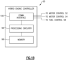
- FIG. 1B schematically shows an example implementation of the hybrid engine controller 50 of Figure 1A .
- the controller 50 includes processing circuitry 96 operatively connected to memory 98 and a communication interface 100.
- the processing circuitry 96 may include one or more microprocessors, microcontrollers, application specific integrated circuits (ASICs), or the like.
- the memory 98 may include any one or combination of volatile memory elements (e.g., random access memory (RAM, such as DRAM, SRAM, SDRAM, VRAM, etc.)) and/or nonvolatile memory elements (e.g., ROM, hard drive, tape, CD-ROM, etc.).
- the memory 98 may incorporate electronic, magnetic, optical, and/or other types of storage media.
- the memory 98 stores instructions which, when executed by the processing circuitry 96, cause the processing circuitry 96 to implement the various features discussed below (e.g., the method of Figure 3 ).
- the communication interface 100 is operable to facilitate communication between the controller 24 and other devices, such as controls 52, 54 and 58.
- the hybrid engine controller 50 may be a model predictive control (MPC) that allows the controller to project into the future what demands will be placed on the overall hybrid engine 20, and can predict when the do not exceed line 84/90 (as illustrated in Figure 4 ) will be reached.
- MPC model predictive control
- the electric motors 42 and/or 48 may supplement power generated by the gas turbine engine 21.
- the gas turbine engine 21 may be required to provide the power sufficient to keep an associated aircraft flying.
- Figure 2 is a graph showing N1 speed against time.
- N1 is the speed of the low spool.
- a pilot or computer system in an unmanned aircraft
- a take-off speed for N1 such as by operating the throttle of the associated aircraft.
- Line 78 illustrates a baseline N1 speed rate in a standard gas turbine engine (e.g., not a hybrid engine).
- Line 80 illustrates a normal N1 speed rate to the commanded speed 76 for a properly functioning hybrid engine.
- line 82 shows how the speed would approach the commanded speed 76 in the event of an electric motor failure.
- Figure 2 is a graph showing the N1 speed, it should be understood that other variables indicative of the overall operation of the hybrid engine 20, and in particular an apparent failure of an electric motor, could be utilized. As examples only, the provided thrust of the hybrid engine 20 or the speed of a high pressure spool including a turbine 38, shaft 36, and compressor 34 may be monitored.
- FIG. 3 is a flowchart of operation of the hybrid engine 20 under this disclosure.
- the method of this disclosure monitors the N1 speed and asks if the baseline 78 is greater than the actual N1 (e.g., line 82) by a predetermined amount at a particular time. If the answer is no, then at step 72 the hybrid engine controller 50 operates the hybrid engine 20 in a mode 1 as explained below with reference to Figure 4 . However, should the hybrid engine controller 50 determine that the baseline 78 is greater than the actual N1 by more than a predetermined maximum at the particular time, then at step 74 the controller is programmed to, based on that determination, move operation of at least one of the compressors to mode 2.
- the hybrid engine controller 50 would be controlling the overall hybrid engine 20 to achieve a number of distinct goals.
- temperature limits across the engine and absolute pressure limits are monitored and controlled.
- the difference between mode 1 and mode 2 in this disclosure has to do with a pressure ratio across at least one of the compressors 30 and 34.
- the high pressure compressor 34 is controlled between modes 1 and 2, and the low speed spool speed N1 is used to identify a motor failure.
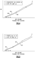
- Figure 4 shows a graph of pressure ratio across the high pressure compressor 34 against air volume delivered into the high pressure compressor 34 in pounds per second. This is mode 1 operation. A region X is shown early in the operation of the hybrid engine 20. As shown, a "not to exceed" line 84 is determined to identify a pressure ratio that could result in stall of the high pressure compressor 34. Stall of a compressor in a gas turbine engine 21 is an undesired occurrence.
- the hybrid engine controller 50 changes that percentage (e.g., the first percentage) should a determination be made that the electric motor may have failed, and such that the percentage is less in mode 2 than it was in mode 1.
- Curve 86 is an operating line that the controller 50 attempts to drive the high pressure compressor 34 to achieve.
- the hybrid engine controller 50 maintains the actual operating line 86 to be spaced from the do not exceed line 84 by an amount 88.
- the mode 2 is entered if there is an identification by hybrid engine controller 50 that at least one electric motor has apparently failed.
- the do not exceed curve 90 and actual operating line 92 are illustrated.
- an early period Y there is a time period identified at 94 wherein the operating line 92 is moved much closer to the do not exceed line 90 than was utilized in mode 1 of Figure 4 .
- the difference between the operating line 86 and the do not exceed line 84 in the Figure 4 normal operation may be on the order of five percent, as an example. However, in the control mode 2 as shown in Figure 5 , that difference will be much less. As an example, the difference may be less than five percent. In other embodiments, the difference could be less than two percent. In other embodiments, the difference could be less than .05 percent. In fact, the hybrid engine controller 50 attempts to drive operating line 86 to be equal to the do not exceed line 90 through this early period of operation Y.
- the hybrid engine controller 50 controls the fuel control 58 and other end effectors to drive the high pressure compressor 34 to achieve the pressure ratios in modes 1 and 2.
- the hybrid engine controller 50 is programmed to minimize the time it will take for the hybrid engine 20 to reach the commanded speed 80 in the event of an electric motor failure. At the same time, the hybrid engine controller 50 is operating to avoid temperature limits and absolute pressure limits on the components within the gas turbine engine 21.
- control fault detection and analysis logic is not involved in the method of this disclosure.
- the controller 50 is using a closing loop on speed N1, other speed, or thrust of the engine. No failure detection is required of the motors 42 or 48 for the operating line change between mode 1 and mode 2.
- the hybrid engine controller 50 simply receives feedback on the N1 speed, or thrust, or other speed, and identifies that is it is not where it should be. Hybrid engine controller 50 then commands more fuel to the combustor. If the required acceleration is significant enough that the compressor is projected by the hybrid engine controller 50 to exceed the do not exceed line or curve, the hybrid engine controller 50 slows the acceleration down such that the actual operating line remains under the do not exceed limit, but the engine continues to accelerate as quickly as possible.
- a hybrid engine under this disclosure could be said to include a gas turbine engine having at least one compressor rotor connected to be driven by at least one turbine rotor.
- a combustor is connected to receive compressed air from the at least one compressor rotor, and to receive fuel.
- At least one electric motor is connected to drive the at least one compressor rotor to supplement drive in combination with from the at least one turbine rotor.
- a hybrid engine controller includes processing circuitry and memory storing instructions that, when executed cause the processing circuitry to control a flow of the fuel to the combustor, control the at least one electric motor. Feedback is received on an operating condition of the hybrid engine indicative of a failure of the at least one electric motor.
- the at least one compressor is controlled in a first mode to operate at a compressor pressure ratio spaced from a stall pressure ratio that could result in a stall of the at least one compressor based on the operating condition not indicating a potential failure of the at least one electric motor.
- the at least one compressor is controlled to move to a second mode where the compressor pressure ratio is closer to the stall pressure ratio than in the first mode based on the hybrid engine controller determining that a failure of the at least one electric motor occurred.
- a method of operating a hybrid engine under this disclosure could be said to include the steps of operating a gas turbine engine having at least one compressor rotor driven by at least one turbine rotor, a combustor connected to receive compressed air from the at least one compressor rotor, and to receive fuel. At least one electric motor is operated to drive the at least one compressor rotor to supplement drive provided by the at least one turbine rotor. A flow of fuel is controlled to the combustor. Feedback is received on an operating condition of the hybrid engine indicative of a failure of the at least one electric motor.
- the at least one compressor is controlled in a first mode to achieve a compressor pressure ratio spaced from a stall pressure ratio across the at least one compressor that could result in a stall of the at least one compressor based on the operating condition not indicating a failure of the electric motor.
- the at least one compressor is controlled in a second mode where the compressor pressure ratio is closer to the stall pressure ratio than in the first mode based on the operating condition indicating an electric motor failure.
Landscapes
- Engineering & Computer Science (AREA)
- Chemical & Material Sciences (AREA)
- Combustion & Propulsion (AREA)
- Aviation & Aerospace Engineering (AREA)
- Mechanical Engineering (AREA)
- General Engineering & Computer Science (AREA)
- Control Of Positive-Displacement Air Blowers (AREA)
Abstract
A hybrid engine (20) includes a gas turbine engine (21) having at least one compressor rotor connected to be driven by at least one turbine rotor. A combustor (40) is connected to receive compressed air from the at least one compressor rotor, and to receive fuel. At least one electric motor (42, 48) is connected to drive the at least one compressor rotor to supplement drive in combination with the at least one turbine rotor. A hybrid engine controller (50) includes processing circuitry (96) and a memory (98) storing instructions that, when executed cause the processing circuitry (96) to control a flow of the fuel to the combustor (40), control the at least one electric motor (42, 48). Feedback is received on an operating condition of the hybrid engine (20) indicative of a failure of the at least one electric motor (42, 48). The at least one compressor (30, 34) is controlled in a first mode to operate at a compressor pressure ratio spaced from a stall pressure ratio that could result in a stall of the at least one compressor (30, 34) based on the operating condition not indicating a potential failure of the at least one electric motor (42, 48). The at least one compressor (30, 34) is controlled to move to a second mode where the compressor pressure ratio is closer to the stall pressure ratio than in the first mode based on the hybrid engine controller (50) determining that a failure of the at least one electric motor failure occurred. A method is also disclosed.
Description
- This application relates to a hybrid engine controller for a hybrid engine including a gas turbine engine and an electric motor, wherein the hybrid engine controller changes operation of a compressor in the gas turbine engine in the event of electric motor failure.
- Hybrid engines are known which incorporate a gas turbine engine and an electric motor.
- An aircraft gas turbine engine typically includes a propulsor delivering air into a core engine having compressor and turbine sections. The air is compressed in the compressor and delivered into a combustor where it is mixed with fuel and ignited. Products of the combustion pass through at least one turbine rotor, driving it to rotate. The turbine rotor in turn drives a compressor rotor.
- More recently, hybrid engines are being considered wherein an electric motor supplements the drive from the turbine section. Thus, at high power operation, such as take off of an aircraft associated with the hybrid engine, the electric motor will supplement the drive to the compressor section. The electric motor may be controlled to stop at lower power operations such as in descent.
- In an aspect of the present invention, a hybrid engine includes a gas turbine engine having at least one compressor rotor connected to be driven by at least one turbine rotor. A combustor is connected to receive compressed air from the at least one compressor rotor, and to receive fuel. At least one electric motor is connected to drive the at least one compressor rotor to supplement drive in combination with the at least one turbine rotor. A hybrid engine controller includes processing circuitry and a memory storing instructions that, when executed cause the processing circuitry to control a flow of the fuel to the combustor, control the at least one electric motor. Feedback is received on an operating condition of the hybrid engine indicative of a failure of the at least one electric motor. The at least one compressor is controlled in a first mode to operate at a compressor pressure ratio spaced from a stall pressure ratio that could result in a stall of the at least one compressor based on the operating condition not indicating a potential failure of the at least one electric motor. The at least one compressor is controlled to move to a second mode where the compressor pressure ratio is closer to the stall pressure ratio than in the first mode based on the hybrid engine controller determining that a failure of the at least one electric motor failure occurred.
- In an embodiment of the above, the at least one compressor rotor includes a low pressure compressor and a high pressure compressor. The at least one turbine rotor includes a high pressure turbine and a low pressure turbine. The low pressure turbine drives the low pressure compressor through a shaft as a low pressure spool, and the high pressure turbine drives the high pressure compressor through a shaft as a high pressure spool.
- In another embodiment according to any of the previous embodiments, the low pressure spool further includes a propulsor.
- In another embodiment according to any of the previous embodiments, the propulsor is driven through a gear reduction.
- In another embodiment according to any of the previous embodiments, the at least one electric motor includes a first electric motor driving the low pressure spool and a second electric motor driving the high pressure spool.
- In another embodiment according to any of the previous embodiments, the operating condition indicative of a potential failure in the at least one electric motor is the speed of the low pressure spool.
- In another embodiment according to any of the previous embodiments, the high pressure compressor is the at least one compressor controlled by the hybrid engine between the first and second modes.
- In another embodiment according to any of the previous embodiments, the condition indicative of the potential failure in the electric motor is the thrust provided by the hybrid engine.
- In another embodiment according to any of the previous embodiments, the hybrid engine controller is a model predictive control.
- In another embodiment according to any of the previous embodiments, the instructions, when executed, cause the processing circuitry to in the first mode, control the compressor pressure ratio across the high pressure compressor to be spaced from the stall pressure ratio by a first higher percentage and in the second mode move the compressor pressure ratio to be closer to the stall pressure ratio than it is in the first mode.
- In another embodiment according to any of the previous embodiments, a percentage difference between the compressor pressure ratio and the stall pressure ratio in the second mode is less than five percent.
- In another embodiment according to any of the previous embodiments, the percentage difference is less than two percent.
- In another embodiment according to any of the previous embodiments, the instructions, when executed cause the processing circuitry to attempt to keep the compressor pressure ratio equal to the stall pressure ratio for at least an early portion of operation of the hybrid engine.
- In another embodiment according to any of the previous embodiments, the early portion of the operation of the hybrid engine occurs at a take-off condition of an associated aircraft.
- In another aspect of the present invention, a method of operating a hybrid engine includes the steps of operating a gas turbine engine having at least one compressor rotor driven by at least one turbine rotor, a combustor connected to receive compressed air from the at least one compressor rotor, and to receive fuel. At least one electric motor is operated to drive the at least one compressor rotor to supplement drive provided by the at least one turbine rotor. A flow of fuel is controlled to the combustor, and controls the at least one electric motor, and receives feedback on an operating condition of the hybrid engine indicative of a failure of the at least one electric motor. The at least one compressor is controlled to in a first mode achieve a compressor pressure ratio spaced from a stall pressure ratio across the at least one compressor that could result in a stall of the at least one compressor based on the operating condition not indicating a failure of the electric motor, and to move to a second mode where the compressor pressure ratio is closer to the stall pressure ratio than in the first mode based on the operating condition indicating an electric motor failure.
- In an embodiment of the above, the at least one compressor rotor includes a low pressure compressor and a high pressure compressor. The at least one turbine rotor includes a high pressure turbine and a low pressure turbine. The low pressure turbine drives the low pressure compressor through a shaft as a low pressure spool, and the high pressure turbine driving the high pressure compressor through a shaft as a high pressure spool
- In another embodiment according to any of the previous embodiments, the operating condition indicative of a potential failure in the at least one electric motor is the speed of the low pressure spool.
- In another embodiment according to any of the previous embodiments, the compressor pressure ratio is across the high pressure compressor.
- In another embodiment according to any of the previous embodiments, in the first mode, the compressor pressure ratio across the high pressure compressor is spaced from the stall pressure ratio by a first higher percentage, and in the second mode the compressor pressure ratio is closer to the stall pressure ratio.
- In another embodiment according to any of the previous embodiments, the condition indicative of the potential failure in the electric motor is the thrust provided by the hybrid engine.
- The present disclosure may include any one or more of the individual features disclosed above and/or below alone or in any combination thereof.
- These and other features of the present invention can be best understood from the following specification and drawings, the following of which is a brief description.
-
-
Figure 1A schematically shows an example hybrid engine. -
Figure 1B schematically shows an example hybrid engine controller. -
Figure 2 is a graph showing several possible scenarios during operation of the hybrid engine ofFigure 1 . -
Figure 3 is a flowchart for a control algorithm under this disclosure. -
Figure 4 shows a graph of pressure ratio versus air mass delivered into a compressor section during a normal acceleration. -
Figure 5 shows a graph of pressure ratio across the compressor section and air mass delivered into the compressor section controlled to operate in a second mode when an electric motor is determined to have failed. -
Figure 1A shows ahybrid engine 20. Thehybrid engine 20 includes agas turbine engine 21 including apropulsor 22, which may be a fan enclosed within afan case 24 to provide bypass air as propulsion.Propulsor 22 is driven by a low pressure turbine section 26 (with one or more rotors).Low pressure turbine 26 drives ashaft 28 to in turn drive alow pressure compressor 30.Low pressure compressor 30 drives agear reduction 32 to in turn drive thepropulsor 22. Thelow pressure turbine 26,shaft 28,low pressure compressor 30 andpropulsor 22 may be referred to as a low pressure spool. - A
high pressure compressor 34 is downstream oflow pressure compressor 30, and is driven by ashaft 36 through a high pressure turbine section 38 (with one or more rotors). Thepropulsor 22 also delivers air into a core engine including thelow pressure compressor 30, which compresses the air and delivers it tohigh pressure compressor 34. The compressed air fromhigh pressure compressor 34 is delivered into acombustor 40 where it is mixed with fuel fromline 41, and ignited. Products of the combustion pass downstream over the highpressure turbine section 38, and then the lowpressure turbine section 26. - A low pressure
electric motor 42 may be configured to drive theshaft 28 through agear transmission 44 and ashaft 45. In such a configuration, thelow pressure compressor 30, thegear reduction 32, and thepropulsor 22 are driven by thelow pressure turbine 26 in combination with the low pressureelectric motor 42. - A high pressure spool is defined by
high pressure compressor 34,shaft 36, andhigh pressure turbine 38. A high pressureelectric motor 48 may additionally be configured to drive the high pressure spool through agear transmission 46 and shaft 47. - A
hybrid engine controller 50 controls a high pressureelectric motor control 52 and a low pressureelectric motor control 54 to achieve a desired speed from the respectiveelectric motors hybrid engine control 50 furthercontrols fuel control 58 to deliver a desired amount of fuel from asource 60 throughline 41 intocombustor 40. Controlling the amount of fuel delivered into thecombustor 40 allows control over the speed and thrust delivered by thegas turbine engine 21. - As shown schematically, a
sensor 51 monitors the speed of thelow pressure spool 26/28/30. - The
hybrid engine controller 50 may include aspects as found in current full authority digital electronic controls ("FADEC") for standard gas turbine engines, and also provided with controls for the electric motors. More generally, the control as utilized to provide the method of this disclosure is described below and illustrated inFigure 1B , schematically. -
Figure 1B schematically shows an example implementation of thehybrid engine controller 50 ofFigure 1A . Thecontroller 50 includesprocessing circuitry 96 operatively connected tomemory 98 and acommunication interface 100. Theprocessing circuitry 96 may include one or more microprocessors, microcontrollers, application specific integrated circuits (ASICs), or the like. Thememory 98 may include any one or combination of volatile memory elements (e.g., random access memory (RAM, such as DRAM, SRAM, SDRAM, VRAM, etc.)) and/or nonvolatile memory elements (e.g., ROM, hard drive, tape, CD-ROM, etc.). Moreover, thememory 98 may incorporate electronic, magnetic, optical, and/or other types of storage media. Thememory 98 stores instructions which, when executed by theprocessing circuitry 96, cause theprocessing circuitry 96 to implement the various features discussed below (e.g., the method ofFigure 3 ). - The
communication interface 100 is operable to facilitate communication between thecontroller 24 and other devices, such ascontrols - The
hybrid engine controller 50 may be a model predictive control (MPC) that allows the controller to project into the future what demands will be placed on theoverall hybrid engine 20, and can predict when the do not exceedline 84/90 (as illustrated inFigure 4 ) will be reached. - During normal operating conditions, the
electric motors 42 and/or 48 may supplement power generated by thegas turbine engine 21. However, in an emergency situation, such as when an electric motor fails, thegas turbine engine 21 may be required to provide the power sufficient to keep an associated aircraft flying. -
Figure 2 is a graph showing N1 speed against time. N1 is the speed of the low spool. As shown at 76, a pilot (or computer system in an unmanned aircraft) has commanded a take-off speed for N1, such as by operating the throttle of the associated aircraft.Line 78 illustrates a baseline N1 speed rate in a standard gas turbine engine (e.g., not a hybrid engine).Line 80 illustrates a normal N1 speed rate to the commandedspeed 76 for a properly functioning hybrid engine. However,line 82 shows how the speed would approach the commandedspeed 76 in the event of an electric motor failure. - While
Figure 2 is a graph showing the N1 speed, it should be understood that other variables indicative of the overall operation of thehybrid engine 20, and in particular an apparent failure of an electric motor, could be utilized. As examples only, the provided thrust of thehybrid engine 20 or the speed of a high pressure spool including aturbine 38,shaft 36, andcompressor 34 may be monitored. -
Figure 3 is a flowchart of operation of thehybrid engine 20 under this disclosure. - At
step 70, the method of this disclosure monitors the N1 speed and asks if thebaseline 78 is greater than the actual N1 (e.g., line 82) by a predetermined amount at a particular time. If the answer is no, then atstep 72 thehybrid engine controller 50 operates thehybrid engine 20 in amode 1 as explained below with reference toFigure 4 . However, should thehybrid engine controller 50 determine that thebaseline 78 is greater than the actual N1 by more than a predetermined maximum at the particular time, then atstep 74 the controller is programmed to, based on that determination, move operation of at least one of the compressors to mode 2. - It should be understood that in any such hybrid engine, the
hybrid engine controller 50 would be controlling theoverall hybrid engine 20 to achieve a number of distinct goals. As an example, temperature limits across the engine and absolute pressure limits are monitored and controlled. However, the difference betweenmode 1 and mode 2 in this disclosure has to do with a pressure ratio across at least one of thecompressors - In a disclosed embodiment, the
high pressure compressor 34 is controlled betweenmodes 1 and 2, and the low speed spool speed N1 is used to identify a motor failure. -
Figure 4 shows a graph of pressure ratio across thehigh pressure compressor 34 against air volume delivered into thehigh pressure compressor 34 in pounds per second. This ismode 1 operation. A region X is shown early in the operation of thehybrid engine 20. As shown, a "not to exceed"line 84 is determined to identify a pressure ratio that could result in stall of thehigh pressure compressor 34. Stall of a compressor in agas turbine engine 21 is an undesired occurrence. - In known gas turbine engine controls, the pressure ratio that could lead to stall, and as shown here do not exceed
line 84, is known. Known gas turbine engine controls typically avoid the pressure ratio that could potentially result in stall by a first percentage. - As disclosed herein, the
hybrid engine controller 50 changes that percentage (e.g., the first percentage) should a determination be made that the electric motor may have failed, and such that the percentage is less in mode 2 than it was inmode 1. -
Curve 86 is an operating line that thecontroller 50 attempts to drive thehigh pressure compressor 34 to achieve. - As known, the likelihood of stall is greatest at an early point in operation identified by area X.
- During the entire operation of the hybrid engine, the
hybrid engine controller 50 maintains theactual operating line 86 to be spaced from the do not exceedline 84 by anamount 88. - However, should a failure event occur as shown at
curve 82 inFigure 2 , there may be insufficient time to achieve take-off thrust shouldengine 21 continue to operate inmode 1. - Thus, as shown in
Figure 5 , the mode 2 is entered if there is an identification byhybrid engine controller 50 that at least one electric motor has apparently failed. In the control mode 2 illustrated inFigure 5 , the do not exceedcurve 90 andactual operating line 92 are illustrated. In an early period Y, there is a time period identified at 94 wherein the operatingline 92 is moved much closer to the do not exceedline 90 than was utilized inmode 1 ofFigure 4 . - In embodiments, the difference between the operating
line 86 and the do not exceedline 84 in theFigure 4 normal operation may be on the order of five percent, as an example. However, in the control mode 2 as shown inFigure 5 , that difference will be much less. As an example, the difference may be less than five percent. In other embodiments, the difference could be less than two percent. In other embodiments, the difference could be less than .05 percent. In fact, thehybrid engine controller 50 attempts to drive operatingline 86 to be equal to the do not exceedline 90 through this early period of operation Y. - In one embodiment, the
hybrid engine controller 50 controls thefuel control 58 and other end effectors to drive thehigh pressure compressor 34 to achieve the pressure ratios inmodes 1 and 2. - The
hybrid engine controller 50 is programmed to minimize the time it will take for thehybrid engine 20 to reach the commandedspeed 80 in the event of an electric motor failure. At the same time, thehybrid engine controller 50 is operating to avoid temperature limits and absolute pressure limits on the components within thegas turbine engine 21. - Since the control is part of the
hybrid engine controller 50, control fault detection and analysis logic is not involved in the method of this disclosure. Thecontroller 50 is using a closing loop on speed N1, other speed, or thrust of the engine. No failure detection is required of themotors mode 1 and mode 2. - Instead, the
hybrid engine controller 50 simply receives feedback on the N1 speed, or thrust, or other speed, and identifies that is it is not where it should be.Hybrid engine controller 50 then commands more fuel to the combustor. If the required acceleration is significant enough that the compressor is projected by thehybrid engine controller 50 to exceed the do not exceed line or curve, thehybrid engine controller 50 slows the acceleration down such that the actual operating line remains under the do not exceed limit, but the engine continues to accelerate as quickly as possible. - A hybrid engine under this disclosure could be said to include a gas turbine engine having at least one compressor rotor connected to be driven by at least one turbine rotor. A combustor is connected to receive compressed air from the at least one compressor rotor, and to receive fuel. At least one electric motor is connected to drive the at least one compressor rotor to supplement drive in combination with from the at least one turbine rotor. A hybrid engine controller includes processing circuitry and memory storing instructions that, when executed cause the processing circuitry to control a flow of the fuel to the combustor, control the at least one electric motor. Feedback is received on an operating condition of the hybrid engine indicative of a failure of the at least one electric motor. The at least one compressor is controlled in a first mode to operate at a compressor pressure ratio spaced from a stall pressure ratio that could result in a stall of the at least one compressor based on the operating condition not indicating a potential failure of the at least one electric motor. The at least one compressor is controlled to move to a second mode where the compressor pressure ratio is closer to the stall pressure ratio than in the first mode based on the hybrid engine controller determining that a failure of the at least one electric motor occurred.
- A method of operating a hybrid engine under this disclosure could be said to include the steps of operating a gas turbine engine having at least one compressor rotor driven by at least one turbine rotor, a combustor connected to receive compressed air from the at least one compressor rotor, and to receive fuel. At least one electric motor is operated to drive the at least one compressor rotor to supplement drive provided by the at least one turbine rotor. A flow of fuel is controlled to the combustor. Feedback is received on an operating condition of the hybrid engine indicative of a failure of the at least one electric motor. The at least one compressor is controlled in a first mode to achieve a compressor pressure ratio spaced from a stall pressure ratio across the at least one compressor that could result in a stall of the at least one compressor based on the operating condition not indicating a failure of the electric motor. The at least one compressor is controlled in a second mode where the compressor pressure ratio is closer to the stall pressure ratio than in the first mode based on the operating condition indicating an electric motor failure.
- Although embodiments of this disclosure have been shown, a worker of ordinary skill in this art would recognize that modifications would come within the scope of this disclosure. For that reason, the following claims should be studied to determine the true scope and content of this disclosure.
Claims (15)
- A hybrid engine comprising:a gas turbine engine (21) having at least one compressor rotor connected to be driven by at least one turbine rotor, a combustor (40) connected to receive compressed air from the at least one compressor rotor, and to receive fuel;at least one electric motor (42, 48) connected to drive the at least one compressor rotor to supplement drive in combination with the at least one turbine rotor; anda hybrid engine controller (50) comprising processing circuitry (96) and a memory (98) storing instructions that, when executed cause the processing circuitry (96) to:control a flow of the fuel to the combustor (40);control the at least one electric motor (42, 48);receive feedback on an operating condition of the hybrid engine (20) indicative of a failure of the at least one electric motor (42, 48);control at least one compressor (30, 34) to, in a first mode, operate at a compressor pressure ratio spaced from a stall pressure ratio that could result in a stall of the at least one compressor (30, 34) based on the operating condition not indicating a potential failure of the at least one electric motor (42, 48); andcontrol the at least one compressor (30, 34) to move to a second mode where the compressor pressure ratio is closer to the stall pressure ratio than in the first mode based on the hybrid engine controller (50) determining that a failure of the at least one electric motor occurred.
- The hybrid engine as set forth in claim 1, wherein the at least one compressor rotor includes a low pressure compressor (30) and a high pressure compressor (34), and the at least one turbine rotor includes a high pressure turbine (38) and a low pressure turbine (26), the low pressure turbine (26) driving the low pressure compressor (30) through a shaft (28) as a low pressure spool, and the high pressure turbine (38) driving the high pressure compressor (34) through a shaft (36) as a high pressure spool.
- The hybrid engine as set forth in claim 2, wherein the low pressure spool further includes a propulsor (22), optionally wherein the propulsor (22) is driven through a gear reduction (32).
- The hybrid engine as set forth in claim 2 or 3, wherein the at least one electric motor (42, 48) includes a first electric motor (42) driving the low pressure spool and a second electric motor (48) driving the high pressure spool.
- The hybrid engine as set forth in any of claims 2 to 4, wherein the operating condition indicative of a potential failure in the at least one electric motor (42, 48) is the speed of the low pressure spool.
- The hybrid engine as set forth in any of claims 2 to 5, wherein the high pressure compressor (34) is the at least one compressor (34) controlled by the hybrid engine (20) between the first and second modes.
- The hybrid engine as set forth in any of claims 2 to 6, wherein the instructions, when executed, cause the processing circuitry (96) to:in the first mode, control the compressor pressure ratio across the high pressure compressor (34) to be spaced from the stall pressure ratio by a first higher percentage; andin the second mode move the compressor pressure ratio to be closer to the stall pressure ratio than it is in the first mode.
- The hybrid engine as set forth in any preceding claim, wherein the condition indicative of the potential failure in the electric motor (42, 48) is the thrust provided by the hybrid engine (20).
- The hybrid engine as set forth in any preceding claim, wherein the hybrid engine controller (50) is a model predictive control.
- The hybrid engine as set forth in any preceding claim, wherein a percentage difference between the compressor pressure ratio and the stall pressure ratio in the second mode is less than five percent, optionally wherein the percentage difference is less than two percent.
- The hybrid engine as set forth in any preceding claim, wherein the instructions, when executed cause the processing circuitry (96) to attempt to keep the compressor pressure ratio equal to the stall pressure ratio for at least an early portion of operation of the hybrid engine (20), optionally wherein the early portion of the operation of the hybrid engine (20) occurs at a take-off condition of an associated aircraft.
- A method of operating a hybrid engine including the steps:operating a gas turbine engine (21) having at least one compressor rotor driven by at least one turbine rotor, a combustor (40) connected to receive compressed air from the at least one compressor rotor, and to receive fuel;operating at least one electric motor (42, 48) to drive the at least one compressor rotor to supplement drive provided by the at least one turbine rotor;controlling a flow of fuel to the combustor (40), and controlling the at least one electric motor (42, 48), and receiving feedback on an operating condition of the hybrid engine (20) indicative of a failure of the at least one electric motor (42, 48); andcontrolling at least one compressor (30, 34) to, in a first mode, achieve a compressor pressure ratio spaced from a stall pressure ratio across the at least one compressor (30, 34) that could result in a stall of the at least one compressor (30, 34) based on the operating condition not indicating a failure of the electric motor (42, 48), and to move to a second mode where the compressor pressure ratio is closer to the stall pressure ratio than in the first mode based on the operating condition indicating an electric motor failure.
- The method as set forth in claim 12, wherein the at least one compressor rotor includes a low pressure compressor (30) and a high pressure compressor (34), and the at least one turbine rotor includes a high pressure turbine (38) and a low pressure turbine (26), the low pressure turbine (26) driving the low pressure compressor (30) through a shaft (28) as a low pressure spool, and the high pressure turbine (38) driving the high pressure compressor (34) through a shaft (36) as a high pressure spool, optionally wherein the operating condition indicative of a potential failure in the at least one electric motor (42, 48) is the speed of the low pressure spool.
- The method as set forth in claim 13, wherein the compressor pressure ratio is across the high pressure compressor (34), optionally wherein in the first mode, the compressor pressure ratio across the high pressure compressor (34) is spaced from the stall pressure ratio by a first higher percentage, and in the second mode the compressor pressure ratio is closer to the stall pressure ratio.
- The method as set forth in any of claims 12 to 14, wherein the condition indicative of the potential failure in the electric motor (42, 48) is the thrust provided by the hybrid engine (20).
Applications Claiming Priority (1)
| Application Number | Priority Date | Filing Date | Title |
|---|---|---|---|
| US18/542,099 US20250197019A1 (en) | 2023-12-15 | 2023-12-15 | Hybrid aircraft engine with compressor control for electric motor failure |
Publications (1)
| Publication Number | Publication Date |
|---|---|
| EP4571089A1 true EP4571089A1 (en) | 2025-06-18 |
Family
ID=93924066
Family Applications (1)
| Application Number | Title | Priority Date | Filing Date |
|---|---|---|---|
| EP24219908.1A Pending EP4571089A1 (en) | 2023-12-15 | 2024-12-13 | Hybrid aircraft engine with compressor control for electric motor failure |
Country Status (2)
| Country | Link |
|---|---|
| US (1) | US20250197019A1 (en) |
| EP (1) | EP4571089A1 (en) |
Citations (4)
| Publication number | Priority date | Publication date | Assignee | Title |
|---|---|---|---|---|
| US20220063825A1 (en) * | 2020-08-31 | 2022-03-03 | General Electric Company | Hybrid electric aircraft engine |
| US20220396365A1 (en) * | 2021-06-11 | 2022-12-15 | Raytheon Technologies Corporation | Hybrid electric engine power distribution |
| US20230160347A1 (en) * | 2019-02-07 | 2023-05-25 | Raytheon Technologies Corporation | Adaptive model predictive control for hybrid electric propulsion |
| US20230358169A1 (en) * | 2021-02-08 | 2023-11-09 | General Electric Company | Active compressor stall recovery |
Family Cites Families (4)
| Publication number | Priority date | Publication date | Assignee | Title |
|---|---|---|---|---|
| US9342060B2 (en) * | 2010-09-14 | 2016-05-17 | United Technologies Corporation | Adaptive control for a gas turbine engine |
| US11473496B2 (en) * | 2019-02-05 | 2022-10-18 | Raytheon Technologies Corporation | Transient operation control of a hybrid gas turbine engine |
| US20220397067A1 (en) * | 2021-06-09 | 2022-12-15 | Raytheon Technologies Corporation | Hybrid electric idle transition for aircraft |
| US12320295B2 (en) * | 2021-12-27 | 2025-06-03 | Rolls-Royce North American Technologies, Inc. | Gas turbine engine system with generator |
-
2023
- 2023-12-15 US US18/542,099 patent/US20250197019A1/en active Pending
-
2024
- 2024-12-13 EP EP24219908.1A patent/EP4571089A1/en active Pending
Patent Citations (4)
| Publication number | Priority date | Publication date | Assignee | Title |
|---|---|---|---|---|
| US20230160347A1 (en) * | 2019-02-07 | 2023-05-25 | Raytheon Technologies Corporation | Adaptive model predictive control for hybrid electric propulsion |
| US20220063825A1 (en) * | 2020-08-31 | 2022-03-03 | General Electric Company | Hybrid electric aircraft engine |
| US20230358169A1 (en) * | 2021-02-08 | 2023-11-09 | General Electric Company | Active compressor stall recovery |
| US20220396365A1 (en) * | 2021-06-11 | 2022-12-15 | Raytheon Technologies Corporation | Hybrid electric engine power distribution |
Also Published As
| Publication number | Publication date |
|---|---|
| US20250197019A1 (en) | 2025-06-19 |
Similar Documents
| Publication | Publication Date | Title |
|---|---|---|
| EP3693571B1 (en) | Transient operation control of a hybrid gas turbine engine | |
| US11754001B2 (en) | Aircraft hybrid propulsion system | |
| EP3738888B1 (en) | System and method for operating a multi-engine aircraft | |
| EP2884075B1 (en) | Aircraft engine system comprising a main engine, a starter and an auxiliary power unit | |
| JP2851618B2 (en) | Gas turbine engine bleed control device and control method | |
| EP3073122B1 (en) | Aero gas turbine engine with compressor and associated method | |
| CN111255573B (en) | Method and system for stopping a gas turbine and vehicle | |
| EP3045696A1 (en) | System and method for load power management in a turboshaft gas turbine engine | |
| EP3392485B1 (en) | Fuel control system | |
| WO1994010619A1 (en) | Partial engine and driveshaft failure detection monitor for a multi-engine aircraft | |
| US20220290576A1 (en) | Aircraft propulsion system | |
| EP3118437B1 (en) | Gas turbine engine fuel scheduling | |
| US20240003300A1 (en) | In-flight engine re-start | |
| EP4528110A1 (en) | Method for detecting and annunciating gas turbine engine compressor stall | |
| EP3738875B1 (en) | Method and system for operating a rotorcraft engine | |
| EP4102046A1 (en) | Hybrid electric idle transition for aircraft | |
| CN108150293B (en) | Method and device for controlling extraction on a turbine engine for limiting the risk of surge | |
| CA3002287A1 (en) | Detection of uncommanded and uncontrollable high thrust events | |
| JP2008274931A (en) | Fan control device | |
| EP3705398B1 (en) | Method and system for operating an engine in a multi-engine aircraft | |
| US20250197019A1 (en) | Hybrid aircraft engine with compressor control for electric motor failure | |
| EP4191042A2 (en) | System and method of operating multi-engine system | |
| EP4421574B1 (en) | Gas turbine engine control system | |
| CN119933863B (en) | Aeroengine air starting method and system | |
| WO2002036952A2 (en) | Minimum fuel flow schedule adjustment method for turbine engine control |
Legal Events
| Date | Code | Title | Description |
|---|---|---|---|
| PUAI | Public reference made under article 153(3) epc to a published international application that has entered the european phase |
Free format text: ORIGINAL CODE: 0009012 |
|
| STAA | Information on the status of an ep patent application or granted ep patent |
Free format text: STATUS: THE APPLICATION HAS BEEN PUBLISHED |
|
| AK | Designated contracting states |
Kind code of ref document: A1 Designated state(s): AL AT BE BG CH CY CZ DE DK EE ES FI FR GB GR HR HU IE IS IT LI LT LU LV MC ME MK MT NL NO PL PT RO RS SE SI SK SM TR |
|
| STAA | Information on the status of an ep patent application or granted ep patent |
Free format text: STATUS: REQUEST FOR EXAMINATION WAS MADE |
|
| 17P | Request for examination filed |
Effective date: 20251218 |