EP4571064A1 - An internal engine combustion system - Google Patents
An internal engine combustion system Download PDFInfo
- Publication number
- EP4571064A1 EP4571064A1 EP23217203.1A EP23217203A EP4571064A1 EP 4571064 A1 EP4571064 A1 EP 4571064A1 EP 23217203 A EP23217203 A EP 23217203A EP 4571064 A1 EP4571064 A1 EP 4571064A1
- Authority
- EP
- European Patent Office
- Prior art keywords
- flex
- bellow
- ice
- coil
- ice system
- Prior art date
- Legal status (The legal status is an assumption and is not a legal conclusion. Google has not performed a legal analysis and makes no representation as to the accuracy of the status listed.)
- Pending
Links
Images

Classifications
-
- F—MECHANICAL ENGINEERING; LIGHTING; HEATING; WEAPONS; BLASTING
- F01—MACHINES OR ENGINES IN GENERAL; ENGINE PLANTS IN GENERAL; STEAM ENGINES
- F01N—GAS-FLOW SILENCERS OR EXHAUST APPARATUS FOR MACHINES OR ENGINES IN GENERAL; GAS-FLOW SILENCERS OR EXHAUST APPARATUS FOR INTERNAL-COMBUSTION ENGINES
- F01N3/00—Exhaust or silencing apparatus having means for purifying, rendering innocuous, or otherwise treating exhaust
- F01N3/08—Exhaust or silencing apparatus having means for purifying, rendering innocuous, or otherwise treating exhaust for rendering innocuous
- F01N3/10—Exhaust or silencing apparatus having means for purifying, rendering innocuous, or otherwise treating exhaust for rendering innocuous by thermal or catalytic conversion of noxious components of exhaust
- F01N3/24—Exhaust or silencing apparatus having means for purifying, rendering innocuous, or otherwise treating exhaust for rendering innocuous by thermal or catalytic conversion of noxious components of exhaust characterised by constructional aspects of converting apparatus
- F01N3/28—Construction of catalytic reactors
- F01N3/2892—Exhaust flow directors or the like, e.g. upstream of catalytic device
-
- F—MECHANICAL ENGINEERING; LIGHTING; HEATING; WEAPONS; BLASTING
- F01—MACHINES OR ENGINES IN GENERAL; ENGINE PLANTS IN GENERAL; STEAM ENGINES
- F01N—GAS-FLOW SILENCERS OR EXHAUST APPARATUS FOR MACHINES OR ENGINES IN GENERAL; GAS-FLOW SILENCERS OR EXHAUST APPARATUS FOR INTERNAL-COMBUSTION ENGINES
- F01N13/00—Exhaust or silencing apparatus characterised by constructional features
-
- F—MECHANICAL ENGINEERING; LIGHTING; HEATING; WEAPONS; BLASTING
- F01—MACHINES OR ENGINES IN GENERAL; ENGINE PLANTS IN GENERAL; STEAM ENGINES
- F01N—GAS-FLOW SILENCERS OR EXHAUST APPARATUS FOR MACHINES OR ENGINES IN GENERAL; GAS-FLOW SILENCERS OR EXHAUST APPARATUS FOR INTERNAL-COMBUSTION ENGINES
- F01N13/00—Exhaust or silencing apparatus characterised by constructional features
- F01N13/18—Construction facilitating manufacture, assembly, or disassembly
- F01N13/1805—Fixing exhaust manifolds, exhaust pipes or pipe sections to each other, to engine or to vehicle body
- F01N13/1811—Fixing exhaust manifolds, exhaust pipes or pipe sections to each other, to engine or to vehicle body with means permitting relative movement, e.g. compensation of thermal expansion or vibration
- F01N13/1816—Fixing exhaust manifolds, exhaust pipes or pipe sections to each other, to engine or to vehicle body with means permitting relative movement, e.g. compensation of thermal expansion or vibration the pipe sections being joined together by flexible tubular elements only, e.g. using bellows or strip-wound pipes
-
- F—MECHANICAL ENGINEERING; LIGHTING; HEATING; WEAPONS; BLASTING
- F01—MACHINES OR ENGINES IN GENERAL; ENGINE PLANTS IN GENERAL; STEAM ENGINES
- F01N—GAS-FLOW SILENCERS OR EXHAUST APPARATUS FOR MACHINES OR ENGINES IN GENERAL; GAS-FLOW SILENCERS OR EXHAUST APPARATUS FOR INTERNAL-COMBUSTION ENGINES
- F01N3/00—Exhaust or silencing apparatus having means for purifying, rendering innocuous, or otherwise treating exhaust
- F01N3/08—Exhaust or silencing apparatus having means for purifying, rendering innocuous, or otherwise treating exhaust for rendering innocuous
- F01N3/10—Exhaust or silencing apparatus having means for purifying, rendering innocuous, or otherwise treating exhaust for rendering innocuous by thermal or catalytic conversion of noxious components of exhaust
- F01N3/18—Exhaust or silencing apparatus having means for purifying, rendering innocuous, or otherwise treating exhaust for rendering innocuous by thermal or catalytic conversion of noxious components of exhaust characterised by methods of operation; Control
- F01N3/20—Exhaust or silencing apparatus having means for purifying, rendering innocuous, or otherwise treating exhaust for rendering innocuous by thermal or catalytic conversion of noxious components of exhaust characterised by methods of operation; Control specially adapted for catalytic conversion
- F01N3/2006—Periodically heating or cooling catalytic reactors, e.g. at cold starting or overheating
-
- F—MECHANICAL ENGINEERING; LIGHTING; HEATING; WEAPONS; BLASTING
- F01—MACHINES OR ENGINES IN GENERAL; ENGINE PLANTS IN GENERAL; STEAM ENGINES
- F01N—GAS-FLOW SILENCERS OR EXHAUST APPARATUS FOR MACHINES OR ENGINES IN GENERAL; GAS-FLOW SILENCERS OR EXHAUST APPARATUS FOR INTERNAL-COMBUSTION ENGINES
- F01N3/00—Exhaust or silencing apparatus having means for purifying, rendering innocuous, or otherwise treating exhaust
- F01N3/08—Exhaust or silencing apparatus having means for purifying, rendering innocuous, or otherwise treating exhaust for rendering innocuous
- F01N3/10—Exhaust or silencing apparatus having means for purifying, rendering innocuous, or otherwise treating exhaust for rendering innocuous by thermal or catalytic conversion of noxious components of exhaust
- F01N3/18—Exhaust or silencing apparatus having means for purifying, rendering innocuous, or otherwise treating exhaust for rendering innocuous by thermal or catalytic conversion of noxious components of exhaust characterised by methods of operation; Control
- F01N3/20—Exhaust or silencing apparatus having means for purifying, rendering innocuous, or otherwise treating exhaust for rendering innocuous by thermal or catalytic conversion of noxious components of exhaust characterised by methods of operation; Control specially adapted for catalytic conversion
- F01N3/2006—Periodically heating or cooling catalytic reactors, e.g. at cold starting or overheating
- F01N3/2013—Periodically heating or cooling catalytic reactors, e.g. at cold starting or overheating using electric or magnetic heating means
-
- F—MECHANICAL ENGINEERING; LIGHTING; HEATING; WEAPONS; BLASTING
- F01—MACHINES OR ENGINES IN GENERAL; ENGINE PLANTS IN GENERAL; STEAM ENGINES
- F01N—GAS-FLOW SILENCERS OR EXHAUST APPARATUS FOR MACHINES OR ENGINES IN GENERAL; GAS-FLOW SILENCERS OR EXHAUST APPARATUS FOR INTERNAL-COMBUSTION ENGINES
- F01N3/00—Exhaust or silencing apparatus having means for purifying, rendering innocuous, or otherwise treating exhaust
- F01N3/08—Exhaust or silencing apparatus having means for purifying, rendering innocuous, or otherwise treating exhaust for rendering innocuous
- F01N3/10—Exhaust or silencing apparatus having means for purifying, rendering innocuous, or otherwise treating exhaust for rendering innocuous by thermal or catalytic conversion of noxious components of exhaust
- F01N3/18—Exhaust or silencing apparatus having means for purifying, rendering innocuous, or otherwise treating exhaust for rendering innocuous by thermal or catalytic conversion of noxious components of exhaust characterised by methods of operation; Control
- F01N3/20—Exhaust or silencing apparatus having means for purifying, rendering innocuous, or otherwise treating exhaust for rendering innocuous by thermal or catalytic conversion of noxious components of exhaust characterised by methods of operation; Control specially adapted for catalytic conversion
- F01N3/206—Adding periodically or continuously substances to exhaust gases for promoting purification, e.g. catalytic material in liquid form, NOx reducing agents
- F01N3/2066—Selective catalytic reduction [SCR]
-
- F—MECHANICAL ENGINEERING; LIGHTING; HEATING; WEAPONS; BLASTING
- F01—MACHINES OR ENGINES IN GENERAL; ENGINE PLANTS IN GENERAL; STEAM ENGINES
- F01N—GAS-FLOW SILENCERS OR EXHAUST APPARATUS FOR MACHINES OR ENGINES IN GENERAL; GAS-FLOW SILENCERS OR EXHAUST APPARATUS FOR INTERNAL-COMBUSTION ENGINES
- F01N3/00—Exhaust or silencing apparatus having means for purifying, rendering innocuous, or otherwise treating exhaust
- F01N3/08—Exhaust or silencing apparatus having means for purifying, rendering innocuous, or otherwise treating exhaust for rendering innocuous
- F01N3/10—Exhaust or silencing apparatus having means for purifying, rendering innocuous, or otherwise treating exhaust for rendering innocuous by thermal or catalytic conversion of noxious components of exhaust
- F01N3/18—Exhaust or silencing apparatus having means for purifying, rendering innocuous, or otherwise treating exhaust for rendering innocuous by thermal or catalytic conversion of noxious components of exhaust characterised by methods of operation; Control
- F01N3/20—Exhaust or silencing apparatus having means for purifying, rendering innocuous, or otherwise treating exhaust for rendering innocuous by thermal or catalytic conversion of noxious components of exhaust characterised by methods of operation; Control specially adapted for catalytic conversion
- F01N3/206—Adding periodically or continuously substances to exhaust gases for promoting purification, e.g. catalytic material in liquid form, NOx reducing agents
- F01N3/208—Control of selective catalytic reduction [SCR], e.g. by adjusting the dosing of reducing agent
-
- F—MECHANICAL ENGINEERING; LIGHTING; HEATING; WEAPONS; BLASTING
- F02—COMBUSTION ENGINES; HOT-GAS OR COMBUSTION-PRODUCT ENGINE PLANTS
- F02B—INTERNAL-COMBUSTION PISTON ENGINES; COMBUSTION ENGINES IN GENERAL
- F02B37/00—Engines characterised by provision of pumps driven at least for part of the time by exhaust
-
- F—MECHANICAL ENGINEERING; LIGHTING; HEATING; WEAPONS; BLASTING
- F01—MACHINES OR ENGINES IN GENERAL; ENGINE PLANTS IN GENERAL; STEAM ENGINES
- F01N—GAS-FLOW SILENCERS OR EXHAUST APPARATUS FOR MACHINES OR ENGINES IN GENERAL; GAS-FLOW SILENCERS OR EXHAUST APPARATUS FOR INTERNAL-COMBUSTION ENGINES
- F01N2240/00—Combination or association of two or more different exhaust treating devices, or of at least one such device with an auxiliary device, not covered by indexing codes F01N2230/00 or F01N2250/00, one of the devices being
- F01N2240/16—Combination or association of two or more different exhaust treating devices, or of at least one such device with an auxiliary device, not covered by indexing codes F01N2230/00 or F01N2250/00, one of the devices being an electric heater, i.e. a resistance heater
-
- F—MECHANICAL ENGINEERING; LIGHTING; HEATING; WEAPONS; BLASTING
- F01—MACHINES OR ENGINES IN GENERAL; ENGINE PLANTS IN GENERAL; STEAM ENGINES
- F01N—GAS-FLOW SILENCERS OR EXHAUST APPARATUS FOR MACHINES OR ENGINES IN GENERAL; GAS-FLOW SILENCERS OR EXHAUST APPARATUS FOR INTERNAL-COMBUSTION ENGINES
- F01N2610/00—Adding substances to exhaust gases
- F01N2610/02—Adding substances to exhaust gases the substance being ammonia or urea
Definitions
- the disclosure relates generally to an internal combustion engine (ICE) system.
- the disclosure relates to an ICE system comprising a flex bellow and a heater arrangement.
- the disclosure can be applied to heavy-duty vehicles, such as trucks, buses, and construction equipment, among other vehicle types.
- heavy-duty vehicles such as trucks, buses, and construction equipment, among other vehicle types.
- trucks, buses, and construction equipment among other vehicle types.
- the disclosure may be described with respect to a particular vehicle, the disclosure is not restricted to any particular vehicle.
- Heavy-duty vehicles such as trucks, buses etc. comprising a combustion engine, such as a diesel engine, are typically provided with an exhaust aftertreatment system, EATS, to reduce the emission from the combustion engine.
- EATS exhaust aftertreatment system
- DOC diesel oxidation catalyst
- DPF diesel particulate filter
- SCR selective catalytic reduction SCR catalyst
- liquid reducing agents such as ammonia, urea, and the like.
- the reducing agent is sprayed into the SCR catalyst through a nozzle, or the like, and a chemical reaction is provided between the exhaust from the engine and the reductant, which reduces the amount of NOx ultimately discharged from the EATS.
- the EATS generally consists of a tubular, longitudinal body with an inlet and an outlet, wherein the inlet is arranged on the exhaust side of the ICE, for receiving exhaust gas emissions from the ICE, and an outlet is arranged for discharging exhaust gas emissions treated in the catalytic converter.
- the inlet is in flow communication with the outlet.
- the present disclosure aims to provide an ICE system which further reduces the NOx discharge from the EATS.
- the present disclosure relates to an internal combustion engine (ICE) system comprising:
- the first aspect of the disclosure may seek to induce turbulent flow and heating of the exhaust gas entering the EATS system.
- a technical benefit may include to improve the efficiency of the EATS system thereby further reducing the amount of NOx discharged from the EATS.
- the heating may, for example, constitute of electrical heating.
- the ICE system comprises a turbocharger arrangement having a turbine disposed downstream the ICE in the exhaust conduit and wherein the flex bellow is disposed in-between the turbine and the EATS.
- a technical benefit may include that the flex bellow prevents, at least partially reduces, the vibrations from the turbocharger to reach the EATS.
- the coil is any one of a helical-shaped coil, spiral shaped coil or a conical shaped coil.
- a technical benefit may include a temperature increase combined with a reduced pressure drop of the exhaust gas due to the specific shape of the heater arrangement.
- the coil extends along 1/3 or more of a length of the flex bellow.
- a technical benefit may include a temperature increase combined with a reduced pressure drop of the exhaust gas.
- the coil extends along 1/2 or more of a length of the flex bellow.
- a technical benefit may include a further temperature increase combined with a reduced pressure drop of the exhaust gas.
- the coil extends along the entire length of the flex bellow.
- a technical benefit may include a maximized temperature increase combined with a reduced pressure drop of the exhaust gas.
- the heater arrangement is arranged with a distance to an inner surface of the flex bellow, thereby providing a gap between the heater arrangement and the inner surface of the flex bellow.
- a technical benefit may be that a larger surface area of the heater arrangement is exposed to the air flow which enhances the heating efficiency. This has additionally been found to further induce turbulent flow of the exhaust gas, thereby improving the efficiency of the EATS when the exhaust gas enters the EATS.
- the heater arrangement is connected to an inner surface of the flex bellow by one or more connection points.
- a technical benefit may include an improved structure for inducing turbulent flow of the exhaust gas, thereby further improving the efficiency of the EATS when the exhaust gas enters the EATS.
- the one or more connection points comprises an insulating flexible material. This has been found to avoid transfer of heat from the heating arrangement to the inner surface of flex bellow.
- the one or more connection points comprise(s) a spring connection. This has been found to minimize the vibrations transferring to the coil by providing damping.
- a first reductant injector for introducing a liquid reducing agent, such as urea is arranged in-between the turbine and the flex bellow.
- a liquid reducing agent such as urea
- the fact that the flex bellow with the heater is arranged downstream the first reductant injection has the advantage of the heating the reductant prior to entering the EATS.
- a further technical advantage is an improved distribution of the reductant in the exhaust gas caused by the turbulent gas flow.
- a technical benefit may include an improved efficiency of the EATS system.
- the one or more heating region is/are arranged in an upstream portion of the flex bellow, the upstream portion constituting of 1/3 of the flex bellow, as seen in a length direction (L) of the flex bellow.
- a technical benefit may include an improved initial heating of the exhaust gas which will enhance the chemical reactions between injected urea and exhaust gases in reducing NOx parameters in the exhaust gases.
- the heater arrangement is provided in the form of a coil comprising two or more loops.
- a technical benefit may include to further induce the turbulent flow of the exhaust gas, thereby improving the efficiency of the EATS when the exhaust gas enters the EATS.
- the heater arrangement is provided in the form of a coil comprising three or more loops.
- a technical benefit may include to even further induce the turbulent flow of the exhaust gas, thereby improving the efficiency of the EATS when the exhaust gas enters the EATS.
- the one or more heating regions extend over at least 1/3 of a total length of the coil.
- a technical benefit may include, uniform temperature maintained throughout the length of the flex bellow.
- the one or more heating regions extend over the entire length of the coil.
- a technical benefit may include a uniform temperature maintained throughout the entire length of the flex bellow.
- the second turbulent flow inducing device is a stationary propeller-shaped device.
- a technical benefit may include an improved mixing of the urea in the exhaust gas prior to entering the EATS system and an increased efficiency of the EATS system.
- the stationary propeller-shaped device is arranged within the coil.
- a technical benefit may include a further improved mixing of the urea in the exhaust gas prior to entering the EATS system and an increased efficiency of the EATS system.
- the EATS may include one or more of; a DOC, a DPF and one or two SCR catalysts.
- a vehicle comprising the ICE system according to the first aspect.
- the second aspect of the disclosure may seek to induce turbulent flow and heating of the exhaust gas entering the EATS system.
- a technical benefit may include to improve the efficiency of the EATS system of the vehicle thereby further reducing the amount of NOx discharged from the EATS.
- SCR is an effective exhaust aftertreatment technology for reducing nitrogen oxide (NOx) emissions.
- NOx nitrogen oxide
- SCR catalysts are widely used in heavy-duty vehicles due to NOx emission regulations.
- liquid reducing agents such as ammonia, urea, and the like.
- the reducing agent is sprayed into the SCR catalyst through a nozzle, or the like, and a chemical reaction is provided between the exhaust from the engine and the reductant, which reduces the amount of NOx ultimately discharged from the EATS.
- the ICE system as described herein may seek to induce turbulent flow and heating of the exhaust gas entering the EATS system.
- a technical benefit may include to improve the efficiency of the EATS system thereby further reducing the amount of NOx discharged from the EATS.
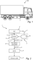
- FIG. 1 illustrates a vehicle 100 according to an example.
- the vehicle 100 comprising an internal combustion engine (ICE) system 1.
- ICE internal combustion engine
- the vehicle 100 depicted in Fig. 1 is a truck 100 for which the inventive concept which will be described in detail below, is suitable for.
- FIG. 2 shows a flowchart of the ICE system 1 according to an example.
- the ICE system 1 comprising an ICE 2, such as a diesel engine.
- a turbocharger 3 comprising a turbine 4 is arranged downstream the ICE 1 in an exhaust conduit 5 for transporting exhaust gases from the ICE 1 to an exhaust outlet 6.
- the turbocharger 3 of the ICE system 1 may generally refer to a well-known arrangement, in which a turbine 4 of the turbocharger 3 is arranged to receive exhaust gases from the ICE 2 and a compressor 3a is configured to compress intake air and feed the compressed intake air via an air intake line 7 to the ICE 2, while the turbine 4 being configured to convert engine exhaust gas into mechanical energy to drive the compressor.
- the turbocharger 3 is however an optional feature of the present disclosure.
- the ICE system 1 furthermore comprises a flex bellow 8, which may also be denoted as a flex coupling or a flex hub, arranged downstream the ICE 2 and the turbocharger 3 and which is arranged to receive the exhaust gases from the ICE 2.
- the flex bellow 8 may prevent, or at least reduce, vibration from the turbocharger 3 due to its structure.
- An EATS 9 is disposed in the exhaust conduit 5 downstream the flex bellow 8.
- the EATS may include one or more of a pre-SCR, a DPF, a DOC, a first SCR catalyst and a second SCR catalyst (not shown). If present, the pre-SCR insert is arranged to receive exhaust gas entering the EATS 9 and the DPF is arranged downstream the pre-SCR.
- the EATS 9 preferably comprises one or more SCR catalyst(s).
- a first reductant injector 10, such as a urea injector may be positioned in the exhaust pipe, upstream the flex bellow 8 for introducing a liquid reducing agent, such as urea.
- a second reductant injector 11 may be arranged upstream the first SCR catalyst.
- the present ICE system 1 comprises the flex bellow 8 provided with the heater arranged downstream the first reductant injector 10, according to the present disclosure, has the advantage of pre-heating of the liquid reducing agent prior to entering the EATS 9 and additionally improving distribution of the liquid reducing agent caused by the turbulent gas flow.
- a technical benefit may include an improved efficiency of the ICE system 1.
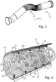
- FIG. 3 shows a perspective view of the flex bellow 8 and the exhaust pipe 5 upstream the flex bellow 8 according to an example.
- the flex bellow 8 and the exhaust pipe 5 extending in a longitudinal direction L.
- the flex bellow 8 of the ICE system 1 may generally refer to a convoluted tube junction, mechanically joining the two ends of the exhaust pipe, and forming part of the exhaust pipe, and is provided to convey the exhaust gas therein.
- the primary use thereof is generally to aid in absorbing excess vibrations and movement caused by the engine and the linear movement as the exhaust system heats up and expands during use.
- a further technical benefit is that it prevents, at least partially reduces, the vibration from the turbocharger 3 to reach the EATS 9.
- FIG. 4 shows a portion of the flex bellow 8 according to an example such the interior of the flex bellow 8 is illustrated.
- the flex bellow 8 comprises a heater arrangement 12 being arranged within the flex bellow 8.
- the heater arrangement 12 is in the form of a coil, in the figure a first coil 12a having one or more heating regions 13 and one or more portions 14 configured to induce turbulent flow of the exhaust gases.
- the heater arrangement 12 comprises a second coil 12b, the first and second coil 12a, 12b having phase difference such that the first coil 12a is arranged with an anti-clockwise rotation and the second coil 12b is arranged with a clockwise rotation.
- the heater arrangement 12 according to the present disclosure may comprise one single coil or alternatively three or four coils.
- the heater arrangement 12 may alternatively be provided with both clockwise directions or both anti-clockwise directions with a phase difference.
- turbulent flow is meant an irregular flow wherein the flow undergoes irregular fluctuations, in contrast to a laminar flow.
- the turbulent flow is at least partly caused by the shape of the heater arrangement 12.
- the heater arrangement 12 in FIG. 4 comprises two coils 12a, 12b having a helical shape and being arranged in the flex bellow 8, each coil 12a, 12b comprising two or more loops 13a, 13b.
- the coils 12a, 12b each extend along the entire length l fb of the flex bellow 8 in this figure. However, alternatively, the coil(s) may extend along 1/3 or more, or along 1/2 or more of, the length l fb of the flex bellow 8.
- the heater arrangement 12 is arranged with a distance to an inner surface 15 of the flex bellow 8, thereby providing a gap between the heater arrangement 12 and the inner surface 15 of the flex bellow 8.
- the fact that heater arrangement 12 is provided with a distance to the inner surface 15 of the flex bellow 8 allows the exhaust gases to be in contact with the a larger surface area of the heater arrangement 12 making the heating more effective and it also causes an irregular flow of the exhaust gas thereby inducing the turbulent flow, which provides an improved mixing of the reductant from the first reductant injector 10.
- the heater arrangement is connected to an inner surface 15 of the flex bellow by one or more connection points 16.
- the one or more connection points 16 may comprise an insulating flexible material, and may furthermore comprise a spring connection.
- the fact that the one or more connection points comprises insulating and/or a spring connection provides vibration damping transferring to the coil 12 from flex bellow 8 and avoids transfer of heat from the coil 12 to the flex bellow 8.
- the one or more heating regions 14 may extend over at least 1/3 of a total length l c of the coils 12a, 12b. Alternatively, the one or more heating regions extend over at least 1/2 of the total length l c of the coils 12a, 12b, or over the entire length l c of the coil.
- FIG. 5 illustrates a portion of the interior the flex bellow 8 according to an example.
- the flex bellow 8 comprises the heater arrangement 12 being arranged within the flex bellow 8.
- the heater arrangement 12 has a coil 12a having a helical shape and configured to induce turbulent flow of the exhaust gases.
- the heater arrangement is connected to the inner surface 15 of the flex bellow by one or more connection points 16.
- the one or more connection points 16 may comprise an insulating flexible material, and may furthermore comprise a spring connection.
- the flex bellow 8 comprises a second turbulent flow inducing device 17 in the form of a stationary propeller-shaped device.
- the stationary propeller-shaped device 17 is arranged within the coil 12a and provides a further induced turbulent flow of the exhaust gases.
- Example 1 An internal engine combustion (ICE) system, comprising:
- Example 2 The ICE system of example 1, wherein the ICE system further comprises a turbocharger arrangement having a turbine disposed downstream the ICE in the exhaust conduit and wherein the flex bellow is disposed in-between the turbine and the EATS.
- Example 3 The ICE system of example 1 or 2, wherein the coil is any one of a helical-shaped coil, spiral shaped coil or a conical shaped coil.
- Example 4 The ICE system of any one of examples 1 to 3, wherein the coil extends along 1/3 or more of a length of the flex bellow.
- Example 5 The ICE system of any one of examples 1 to 3, wherein the coil extends along 1/2 or more of a length of the flex bellow.
- Example 6 The ICE system of any one of examples 1 to 3, wherein the coil extends along the entire length of the flex bellow.
- Example 7 The ICE system of any one of the preceding examples, wherein the heater arrangement is arranged with a distance to an inner surface of the flex bellow, thereby providing a gap between the heater arrangement and the inner surface of the flex bellow.
- Example 8 The ICE system of any one of the preceding examples, wherein the heater arrangement is connected to an inner surface of the flex bellow by one or more connection points.
- Example 9 The ICE system of example 8, wherein the one or more connection points comprises an insulating flexible material.
- Example 10 The ICE system of example 8 or 9, wherein the one or more connection points comprise(s) a spring connection.
- Example 11 The ICE system of any one of the preceding examples, wherein a urea injector is arranged in-between the turbine and the flex bellow.
- Example 12 The ICE system of any one of the preceding examples, wherein the one or more heating region is/are arranged in an upstream portion of the flex bellow, the upstream portion constituting of 1/3 of the flex bellow, as seen in a length direction (L) of the flex bellow.
- Example 13 The ICE system of any one of the preceding examples, wherein the heater arrangement is provided in the form of a coil comprising two or more loops.
- Example 14 The ICE system of any one of the preceding examples, wherein the heater arrangement is provided in the form of a coil comprising three or more loops.
- Example 15 The ICE system of any one of the preceding examples, wherein the one or more heating regions extend over at least 1/3 of a total length of the coil.
- Example 16 The ICE system of any one of examples 1 to 14, wherein the one or more heating regions extend over the entire length of the coil.
- Example 17 The ICE system of any one of the preceding examples, wherein the flex bellow comprises a second turbulent flow inducing device.
- Example 18 The ICE system of example 17, wherein the second turbulent flow inducing device is a stationary propeller-shaped device.
- Example 19 The ICE system of example 18, wherein the stationary propeller-shaped device is arranged within the coil.
- Example 20 A vehicle comprising the ICE system according to any one of the preceding examples.
- Relative terms such as “below” or “above” or “upper” or “lower” or “horizontal” or “vertical” may be used herein to describe a relationship of one element to another element as illustrated in the Figures. It will be understood that these terms and those discussed above are intended to encompass different orientations of the device in addition to the orientation depicted in the Figures. It will be understood that when an element is referred to as being “connected” or “coupled” to another element, it can be directly connected or coupled to the other element, or intervening elements may be present. In contrast, when an element is referred to as being “directly connected” or “directly coupled” to another element, there are no intervening elements present.
Landscapes
- Engineering & Computer Science (AREA)
- Chemical & Material Sciences (AREA)
- Chemical Kinetics & Catalysis (AREA)
- Combustion & Propulsion (AREA)
- Mechanical Engineering (AREA)
- General Engineering & Computer Science (AREA)
- Health & Medical Sciences (AREA)
- Toxicology (AREA)
- Exhaust Gas After Treatment (AREA)
Abstract
- an ICE (2);
- an exhaust conduit (5) for transporting exhaust gases from the ICE (2) to an exhaust outlet (6);
- an EATS (9) disposed in the exhaust conduit (5) downstream the ICE (2);
- a flex bellow (8) disposed in-between the ICE (2) and the EATS (9); and
- a heater arrangement (12), the heater arrangement (12) being arranged within the flex bellow (8) and further provided in the form of a coil (12a, 12b) having one or more heating regions (13) and one or more portions (14) configured to induce turbulent flow of the exhaust gases.
Description
- The disclosure relates generally to an internal combustion engine (ICE) system. In particular aspects, the disclosure relates to an ICE system comprising a flex bellow and a heater arrangement. The disclosure can be applied to heavy-duty vehicles, such as trucks, buses, and construction equipment, among other vehicle types. Although the disclosure may be described with respect to a particular vehicle, the disclosure is not restricted to any particular vehicle.
- Heavy-duty vehicles, such as trucks, buses etc. comprising a combustion engine, such as a diesel engine, are typically provided with an exhaust aftertreatment system, EATS, to reduce the emission from the combustion engine.
- For such EATS arrangements a diesel oxidation catalyst (DOC), a diesel particulate filter (DPF) and one or two selective catalytic reduction SCR catalyst(s) are generally used.
- These systems use liquid reducing agents such as ammonia, urea, and the like. The reducing agent is sprayed into the SCR catalyst through a nozzle, or the like, and a chemical reaction is provided between the exhaust from the engine and the reductant, which reduces the amount of NOx ultimately discharged from the EATS.
- The EATS generally consists of a tubular, longitudinal body with an inlet and an outlet, wherein the inlet is arranged on the exhaust side of the ICE, for receiving exhaust gas emissions from the ICE, and an outlet is arranged for discharging exhaust gas emissions treated in the catalytic converter. The inlet is in flow communication with the outlet.
- Due to stricter requirements, there is a need to further reduce the NOx discharge from the EATS.
- In view of the above, the present disclosure aims to provide an ICE system which further reduces the NOx discharge from the EATS.
- According to a first aspect of the disclosure, the present disclosure relates to an internal combustion engine (ICE) system comprising:
- an ICE;
- an exhaust conduit for transporting exhaust gases from the ICE to an exhaust outlet;
- an EATS disposed in the exhaust conduit downstream the ICE;
- a flex bellow disposed in-between the ICE and the EATS; and
- a heater arrangement, the heater arrangement being arranged within the flex bellow and further provided in the form of a coil having one or more heating regions and one or more portions configured to induce turbulent flow of the exhaust gases.
- The first aspect of the disclosure may seek to induce turbulent flow and heating of the exhaust gas entering the EATS system. A technical benefit may include to improve the efficiency of the EATS system thereby further reducing the amount of NOx discharged from the EATS.
- The heating may, for example, constitute of electrical heating.
- Optionally in some examples, including in at least one preferred example, the ICE system comprises a turbocharger arrangement having a turbine disposed downstream the ICE in the exhaust conduit and wherein the flex bellow is disposed in-between the turbine and the EATS. A technical benefit may include that the flex bellow prevents, at least partially reduces, the vibrations from the turbocharger to reach the EATS.
- Optionally in some examples, including in at least one preferred example, the coil is any one of a helical-shaped coil, spiral shaped coil or a conical shaped coil. A technical benefit may include a temperature increase combined with a reduced pressure drop of the exhaust gas due to the specific shape of the heater arrangement.
- Optionally in some examples, including in at least one preferred example, the coil extends along 1/3 or more of a length of the flex bellow. A technical benefit may include a temperature increase combined with a reduced pressure drop of the exhaust gas.
- Optionally in some examples, including in at least one preferred example, the coil extends along 1/2 or more of a length of the flex bellow. A technical benefit may include a further temperature increase combined with a reduced pressure drop of the exhaust gas.
- Optionally in some examples, including in at least one preferred example, the coil extends along the entire length of the flex bellow. A technical benefit may include a maximized temperature increase combined with a reduced pressure drop of the exhaust gas.
- Optionally in some examples, including in at least one preferred example, the heater arrangement is arranged with a distance to an inner surface of the flex bellow, thereby providing a gap between the heater arrangement and the inner surface of the flex bellow. A technical benefit may be that a larger surface area of the heater arrangement is exposed to the air flow which enhances the heating efficiency. This has additionally been found to further induce turbulent flow of the exhaust gas, thereby improving the efficiency of the EATS when the exhaust gas enters the EATS.
- Optionally in some examples, including in at least one preferred example, the heater arrangement is connected to an inner surface of the flex bellow by one or more connection points. A technical benefit may include an improved structure for inducing turbulent flow of the exhaust gas, thereby further improving the efficiency of the EATS when the exhaust gas enters the EATS.
- Optionally in some examples, including in at least one preferred example, the one or more connection points comprises an insulating flexible material. This has been found to avoid transfer of heat from the heating arrangement to the inner surface of flex bellow.
- Optionally in some examples, including in at least one preferred example, the one or more connection points comprise(s) a spring connection. This has been found to minimize the vibrations transferring to the coil by providing damping.
- Optionally in some examples, including in at least one preferred example, a first reductant injector for introducing a liquid reducing agent, such as urea, is arranged in-between the turbine and the flex bellow. The fact that the flex bellow with the heater is arranged downstream the first reductant injection has the advantage of the heating the reductant prior to entering the EATS. A further technical advantage is an improved distribution of the reductant in the exhaust gas caused by the turbulent gas flow. A technical benefit may include an improved efficiency of the EATS system.
- Optionally in some examples, including in at least one preferred example, the one or more heating region is/are arranged in an upstream portion of the flex bellow, the upstream portion constituting of 1/3 of the flex bellow, as seen in a length direction (L) of the flex bellow. A technical benefit may include an improved initial heating of the exhaust gas which will enhance the chemical reactions between injected urea and exhaust gases in reducing NOx parameters in the exhaust gases.
- Optionally in some examples, including in at least one preferred example, the heater arrangement is provided in the form of a coil comprising two or more loops. A technical benefit may include to further induce the turbulent flow of the exhaust gas, thereby improving the efficiency of the EATS when the exhaust gas enters the EATS.
- Optionally in some examples, including in at least one preferred example, the heater arrangement is provided in the form of a coil comprising three or more loops. A technical benefit may include to even further induce the turbulent flow of the exhaust gas, thereby improving the efficiency of the EATS when the exhaust gas enters the EATS.
- Optionally in some examples, including in at least one preferred example, the one or more heating regions extend over at least 1/3 of a total length of the coil. A technical benefit may include, uniform temperature maintained throughout the length of the flex bellow.
- Optionally in some examples, including in at least one preferred example, the one or more heating regions extend over the entire length of the coil. A technical benefit may include a uniform temperature maintained throughout the entire length of the flex bellow.
- Optionally in some examples, including in at least one preferred example, the second turbulent flow inducing device is a stationary propeller-shaped device. A technical benefit may A technical benefit may include an improved mixing of the urea in the exhaust gas prior to entering the EATS system and an increased efficiency of the EATS system.
- Optionally in some examples, including in at least one preferred example, the stationary propeller-shaped device is arranged within the coil. A technical benefit may include a further improved mixing of the urea in the exhaust gas prior to entering the EATS system and an increased efficiency of the EATS system.
- Optionally in some examples, the EATS may include one or more of; a DOC, a DPF and one or two SCR catalysts.
- According to a second aspect of the disclosure, A vehicle comprising the ICE system according to the first aspect is provided. The second aspect of the disclosure may seek to induce turbulent flow and heating of the exhaust gas entering the EATS system. A technical benefit may include to improve the efficiency of the EATS system of the vehicle thereby further reducing the amount of NOx discharged from the EATS.
- The disclosed aspects, examples (including any preferred examples), and/or accompanying claims may be suitably combined with each other as would be apparent to anyone of ordinary skill in the art. Additional features and advantages are disclosed in the following description, claims, and drawings, and in part will be readily apparent therefrom to those skilled in the art or recognized by practicing the disclosure as described herein.
- Examples are described in more detail below with reference to the appended drawings.
-
FIG. 1 is a side view of a vehicle according to an example. -
FIG. 2 is a flowchart of the ICE system according to an example. -
FIG. 3 is a perspective view of a flex bellow and the upstream exhaust pipe as disclose herein and according to an example. -
FIG. 4 shows a portion of the flex bellow according to an example such the interior of the flex bellow is illustrated. -
FIG. 5 shows a portion of the flex bellow according to a further example such the interior of the flex bellow is illustrated. - The detailed description set forth below provides information and examples of the disclosed technology with sufficient detail to enable those skilled in the art to practice the disclosure.
- SCR is an effective exhaust aftertreatment technology for reducing nitrogen oxide (NOx) emissions. Currently, SCR catalysts are widely used in heavy-duty vehicles due to NOx emission regulations.
- These systems use liquid reducing agents such as ammonia, urea, and the like. The reducing agent is sprayed into the SCR catalyst through a nozzle, or the like, and a chemical reaction is provided between the exhaust from the engine and the reductant, which reduces the amount of NOx ultimately discharged from the EATS.
- To meet further stricter requirements, there is a need to further reduce the NOx discharge from the EATS.
- According to one aspect of the disclosure, the ICE system as described herein may seek to induce turbulent flow and heating of the exhaust gas entering the EATS system. A technical benefit may include to improve the efficiency of the EATS system thereby further reducing the amount of NOx discharged from the EATS.
-
FIG. 1 illustrates avehicle 100 according to an example. Thevehicle 100 comprising an internal combustion engine (ICE)system 1. Thevehicle 100 depicted inFig. 1 is atruck 100 for which the inventive concept which will be described in detail below, is suitable for. -
FIG. 2 shows a flowchart of theICE system 1 according to an example. TheICE system 1 comprising anICE 2, such as a diesel engine. In theICE system 1 as disclosed inFig. 1 , aturbocharger 3 comprising aturbine 4 is arranged downstream theICE 1 in anexhaust conduit 5 for transporting exhaust gases from theICE 1 to anexhaust outlet 6. - The
turbocharger 3 of theICE system 1 may generally refer to a well-known arrangement, in which aturbine 4 of theturbocharger 3 is arranged to receive exhaust gases from theICE 2 and acompressor 3a is configured to compress intake air and feed the compressed intake air via anair intake line 7 to theICE 2, while theturbine 4 being configured to convert engine exhaust gas into mechanical energy to drive the compressor. - The
turbocharger 3 is however an optional feature of the present disclosure. - The
ICE system 1 furthermore comprises aflex bellow 8, which may also be denoted as a flex coupling or a flex hub, arranged downstream theICE 2 and theturbocharger 3 and which is arranged to receive the exhaust gases from theICE 2. Theflex bellow 8 may prevent, or at least reduce, vibration from theturbocharger 3 due to its structure. - An EATS 9 is disposed in the
exhaust conduit 5 downstream theflex bellow 8. The EATS may include one or more of a pre-SCR, a DPF, a DOC, a first SCR catalyst and a second SCR catalyst (not shown). If present, the pre-SCR insert is arranged to receive exhaust gas entering the EATS 9 and the DPF is arranged downstream the pre-SCR. The EATS 9 preferably comprises one or more SCR catalyst(s). - A
first reductant injector 10, such as a urea injector may be positioned in the exhaust pipe, upstream theflex bellow 8 for introducing a liquid reducing agent, such as urea. Asecond reductant injector 11 may be arranged upstream the first SCR catalyst. - The fact that the
present ICE system 1 comprises theflex bellow 8 provided with the heater arranged downstream thefirst reductant injector 10, according to the present disclosure, has the advantage of pre-heating of the liquid reducing agent prior to entering the EATS 9 and additionally improving distribution of the liquid reducing agent caused by the turbulent gas flow. A technical benefit may include an improved efficiency of theICE system 1. -
FIG. 3 shows a perspective view of theflex bellow 8 and theexhaust pipe 5 upstream theflex bellow 8 according to an example. Theflex bellow 8 and theexhaust pipe 5 extending in a longitudinal direction L. Theflex bellow 8 of theICE system 1 may generally refer to a convoluted tube junction, mechanically joining the two ends of the exhaust pipe, and forming part of the exhaust pipe, and is provided to convey the exhaust gas therein. The primary use thereof is generally to aid in absorbing excess vibrations and movement caused by the engine and the linear movement as the exhaust system heats up and expands during use. However, according to the present disclosure a further technical benefit is that it prevents, at least partially reduces, the vibration from theturbocharger 3 to reach the EATS 9. -
FIG. 4 shows a portion of theflex bellow 8 according to an example such the interior of theflex bellow 8 is illustrated. Theflex bellow 8 comprises aheater arrangement 12 being arranged within theflex bellow 8. Theheater arrangement 12 is in the form of a coil, in the figure afirst coil 12a having one ormore heating regions 13 and one ormore portions 14 configured to induce turbulent flow of the exhaust gases. InFIG. 4 , theheater arrangement 12 comprises asecond coil 12b, the first andsecond coil first coil 12a is arranged with an anti-clockwise rotation and thesecond coil 12b is arranged with a clockwise rotation. However, theheater arrangement 12 according to the present disclosure may comprise one single coil or alternatively three or four coils. Theheater arrangement 12 may alternatively be provided with both clockwise directions or both anti-clockwise directions with a phase difference. - By "turbulent flow" is meant an irregular flow wherein the flow undergoes irregular fluctuations, in contrast to a laminar flow. The turbulent flow is at least partly caused by the shape of the
heater arrangement 12. - The
heater arrangement 12 inFIG. 4 comprises twocoils flex bellow 8, eachcoil more loops coils flex bellow 8 in this figure. However, alternatively, the coil(s) may extend along 1/3 or more, or along 1/2 or more of, the length lfb of theflex bellow 8. - The
heater arrangement 12 is arranged with a distance to aninner surface 15 of theflex bellow 8, thereby providing a gap between theheater arrangement 12 and theinner surface 15 of theflex bellow 8. The fact thatheater arrangement 12 is provided with a distance to theinner surface 15 of theflex bellow 8 allows the exhaust gases to be in contact with the a larger surface area of theheater arrangement 12 making the heating more effective and it also causes an irregular flow of the exhaust gas thereby inducing the turbulent flow, which provides an improved mixing of the reductant from thefirst reductant injector 10. - The heater arrangement is connected to an
inner surface 15 of the flex bellow by one or more connection points 16. The one or more connection points 16 may comprise an insulating flexible material, and may furthermore comprise a spring connection. The fact that the one or more connection points comprises insulating and/or a spring connection provides vibration damping transferring to thecoil 12 fromflex bellow 8 and avoids transfer of heat from thecoil 12 to theflex bellow 8. - The one or
more heating regions 14 may extend over at least 1/3 of a total length lc of thecoils coils -
FIG. 5 illustrates a portion of the interior theflex bellow 8 according to an example. Theflex bellow 8 comprises theheater arrangement 12 being arranged within theflex bellow 8. Theheater arrangement 12 has acoil 12a having a helical shape and configured to induce turbulent flow of the exhaust gases. The heater arrangement is connected to theinner surface 15 of the flex bellow by one or more connection points 16. The one or more connection points 16 may comprise an insulating flexible material, and may furthermore comprise a spring connection. In the example shown inFIG. 5 , theflex bellow 8 comprises a second turbulentflow inducing device 17 in the form of a stationary propeller-shaped device. The stationary propeller-shapeddevice 17 is arranged within thecoil 12a and provides a further induced turbulent flow of the exhaust gases. - Example 1: An internal engine combustion (ICE) system, comprising:
- an ICE;
- an exhaust conduit for transporting exhaust gases from the ICE to an exhaust outlet;
- an EATS disposed in the exhaust conduit downstream the ICE;
- a flex bellow disposed in-between the ICE and the EATS; and
- a heater arrangement, the heater arrangement being arranged within the flex bellow and further provided in the form of a coil having one or more heating regions and one or more portions configured to induce turbulent flow of the exhaust gases.
- Example 2: The ICE system of example 1, wherein the ICE system further comprises a turbocharger arrangement having a turbine disposed downstream the ICE in the exhaust conduit and wherein the flex bellow is disposed in-between the turbine and the EATS.
- Example 3: The ICE system of example 1 or 2, wherein the coil is any one of a helical-shaped coil, spiral shaped coil or a conical shaped coil.
- Example 4: The ICE system of any one of examples 1 to 3, wherein the coil extends along 1/3 or more of a length of the flex bellow.
- Example 5: The ICE system of any one of examples 1 to 3, wherein the coil extends along 1/2 or more of a length of the flex bellow.
- Example 6: The ICE system of any one of examples 1 to 3, wherein the coil extends along the entire length of the flex bellow.
- Example 7: The ICE system of any one of the preceding examples, wherein the heater arrangement is arranged with a distance to an inner surface of the flex bellow, thereby providing a gap between the heater arrangement and the inner surface of the flex bellow.
- Example 8: The ICE system of any one of the preceding examples, wherein the heater arrangement is connected to an inner surface of the flex bellow by one or more connection points.
- Example 9: The ICE system of example 8, wherein the one or more connection points comprises an insulating flexible material.
- Example 10: The ICE system of example 8 or 9, wherein the one or more connection points comprise(s) a spring connection.
- Example 11: The ICE system of any one of the preceding examples, wherein a urea injector is arranged in-between the turbine and the flex bellow.
- Example 12: The ICE system of any one of the preceding examples, wherein the one or more heating region is/are arranged in an upstream portion of the flex bellow, the upstream portion constituting of 1/3 of the flex bellow, as seen in a length direction (L) of the flex bellow.
- Example 13: The ICE system of any one of the preceding examples, wherein the heater arrangement is provided in the form of a coil comprising two or more loops.
- Example 14: The ICE system of any one of the preceding examples, wherein the heater arrangement is provided in the form of a coil comprising three or more loops.
- Example 15: The ICE system of any one of the preceding examples, wherein the one or more heating regions extend over at least 1/3 of a total length of the coil.
- Example 16: The ICE system of any one of examples 1 to 14, wherein the one or more heating regions extend over the entire length of the coil.
- Example 17: The ICE system of any one of the preceding examples, wherein the flex bellow comprises a second turbulent flow inducing device.
- Example 18: The ICE system of example 17, wherein the second turbulent flow inducing device is a stationary propeller-shaped device.
- Example 19: The ICE system of example 18, wherein the stationary propeller-shaped device is arranged within the coil.
- Example 20: A vehicle comprising the ICE system according to any one of the preceding examples.
- The terminology used herein is for the purpose of describing particular aspects only and is not intended to be limiting of the disclosure. As used herein, the singular forms "a," "an," and "the" are intended to include the plural forms as well, unless the context clearly indicates otherwise. As used herein, the term "and/or" includes any and all combinations of one or more of the associated listed items. It will be further understood that the terms "comprises," "comprising," "includes," and/or "including" when used herein specify the presence of stated features, integers, actions, steps, operations, elements, and/or components, but do not preclude the presence or addition of one or more other features, integers, actions, steps, operations, elements, components, and/or groups thereof.
- It will be understood that, although the terms first, second, etc., may be used herein to describe various elements, these elements should not be limited by these terms. These terms are only used to distinguish one element from another. For example, a first element could be termed a second element, and, similarly, a second element could be termed a first element without departing from the scope of the present disclosure.
- Relative terms such as "below" or "above" or "upper" or "lower" or "horizontal" or "vertical" may be used herein to describe a relationship of one element to another element as illustrated in the Figures. It will be understood that these terms and those discussed above are intended to encompass different orientations of the device in addition to the orientation depicted in the Figures. It will be understood that when an element is referred to as being "connected" or "coupled" to another element, it can be directly connected or coupled to the other element, or intervening elements may be present. In contrast, when an element is referred to as being "directly connected" or "directly coupled" to another element, there are no intervening elements present.
- Unless otherwise defined, all terms (including technical and scientific terms) used herein have the same meaning as commonly understood by one of ordinary skill in the art to which this disclosure belongs. It will be further understood that terms used herein should be interpreted as having a meaning consistent with their meaning in the context of this specification and the relevant art and will not be interpreted in an idealized or overly formal sense unless expressly so defined herein.
- It is to be understood that the present disclosure is not limited to the aspects described above and illustrated in the drawings; rather, the skilled person will recognize that many changes and modifications may be made within the scope of the present disclosure and appended claims. In the drawings and specification, there have been disclosed aspects for purposes of illustration only and not for purposes of limitation, the scope of the disclosure being set forth in the following claims.
Claims (15)
- An internal combustion engine (ICE) system (1), comprising:- an ICE (2);- an exhaust conduit (5) for transporting exhaust gases from the ICE (2) to an exhaust outlet (6);- an EATS (9) disposed in the exhaust conduit (5) downstream the ICE (2);- a flex bellow (8) disposed in-between the ICE (2) and the EATS (9); and- a heater arrangement (12), the heater arrangement (12) being arranged within the flex bellow (8) and further provided in the form of a coil (12a, 12b) having one or more heating regions (13) and one or more portions (14) configured to induce turbulent flow of the exhaust gases.
- The ICE system (1) of claim 1, wherein the ICE system (1) comprises a turbocharger arrangement (3) having a turbine (4) disposed downstream the ICE (2) in the exhaust conduit (5) and wherein the flex bellow (8) is disposed in-between the turbine (4) and the EATS (9).
- The ICE system (1) of claim 1 or 2, wherein the coil (12a, 12b) is any one of a helical-shaped coil, spiral shaped coil or a conical shaped coil.
- The ICE system (1) of any one of claims 1 to 3, wherein the coil (12a, 12b) extends along 1/2 or more of a total length (lfb) of the flex bellow (8).
- The ICE system (1) of any one of claims 1 to 3, wherein the coil (12a, 12b) extends along the entire length (lfb) of the flex bellow (8).
- The ICE system (1) of any one of the preceding claims, wherein the heater arrangement (12) is arranged with a distance to an inner surface (15) of the flex bellow (8), thereby providing a gap between the heater arrangement (12) and the inner surface (15) of the flex bellow (8).
- The ICE system (1) of any one of the preceding claims, wherein the heater arrangement (12) is connected to an inner surface (15) of the flex bellow (8) by one or more connection points (16).
- The ICE system (1) of claim 7, wherein the one or more connection points (16) comprises an insulating flexible material.
- The ICE system (1) of any one of the preceding claims, wherein a urea injector (10) is arranged in-between the turbine (4) and the flex bellow (8).
- The ICE system (1) of any one of the preceding claims, wherein the one or more heating region (13) is/are arranged in an upstream portion of the flex bellow (8), the upstream portion constituting of 1/3 of the flex bellow (8), as seen in a length direction (L) of the flex bellow (8).
- The ICE system (1) of any one of the preceding claims, wherein the heater arrangement (12) is provided in the form of a coil (12a, 12b) comprising two or more loops.
- The ICE system (1) of any one of claims 1 to 11, wherein the one or more heating regions (13) extend over the entire length of the coil (12a, 12b).
- The ICE system (1) of any one of the preceding claims, wherein the flex bellow (8) comprises a second turbulent flow inducing device (17).
- The ICE system (1) of claim 13, wherein the second turbulent flow inducing device (17) is a stationary propeller-shaped device.
- A vehicle (100) comprising the ICE system (1) according to any one of the preceding claims.
Priority Applications (2)
| Application Number | Priority Date | Filing Date | Title |
|---|---|---|---|
| EP23217203.1A EP4571064A1 (en) | 2023-12-15 | 2023-12-15 | An internal engine combustion system |
| US18/972,917 US20250198320A1 (en) | 2023-12-15 | 2024-12-07 | Internal engine combustion system |
Applications Claiming Priority (1)
| Application Number | Priority Date | Filing Date | Title |
|---|---|---|---|
| EP23217203.1A EP4571064A1 (en) | 2023-12-15 | 2023-12-15 | An internal engine combustion system |
Publications (1)
| Publication Number | Publication Date |
|---|---|
| EP4571064A1 true EP4571064A1 (en) | 2025-06-18 |
Family
ID=89223837
Family Applications (1)
| Application Number | Title | Priority Date | Filing Date |
|---|---|---|---|
| EP23217203.1A Pending EP4571064A1 (en) | 2023-12-15 | 2023-12-15 | An internal engine combustion system |
Country Status (2)
| Country | Link |
|---|---|
| US (1) | US20250198320A1 (en) |
| EP (1) | EP4571064A1 (en) |
Citations (4)
| Publication number | Priority date | Publication date | Assignee | Title |
|---|---|---|---|---|
| GB2307293A (en) * | 1995-11-16 | 1997-05-21 | Ind & Commercial Entpr Ltd | Vehicle exhaust filter |
| DE102004020138B4 (en) * | 2004-04-24 | 2007-02-08 | Daimlerchrysler Ag | Reducing agent addition system |
| US20170014764A1 (en) * | 2013-09-18 | 2017-01-19 | Advanced Technology Emission Solutions Inc. | Apparatus and method for gaseous emissions treatment with directed induction heating |
| CN110821610A (en) * | 2019-12-11 | 2020-02-21 | 湘潭大学 | A kind of gasoline vehicle sleeve type molecular sieve hydrocarbon adsorption type catalytic converter |
-
2023
- 2023-12-15 EP EP23217203.1A patent/EP4571064A1/en active Pending
-
2024
- 2024-12-07 US US18/972,917 patent/US20250198320A1/en active Pending
Patent Citations (4)
| Publication number | Priority date | Publication date | Assignee | Title |
|---|---|---|---|---|
| GB2307293A (en) * | 1995-11-16 | 1997-05-21 | Ind & Commercial Entpr Ltd | Vehicle exhaust filter |
| DE102004020138B4 (en) * | 2004-04-24 | 2007-02-08 | Daimlerchrysler Ag | Reducing agent addition system |
| US20170014764A1 (en) * | 2013-09-18 | 2017-01-19 | Advanced Technology Emission Solutions Inc. | Apparatus and method for gaseous emissions treatment with directed induction heating |
| CN110821610A (en) * | 2019-12-11 | 2020-02-21 | 湘潭大学 | A kind of gasoline vehicle sleeve type molecular sieve hydrocarbon adsorption type catalytic converter |
Also Published As
| Publication number | Publication date |
|---|---|
| US20250198320A1 (en) | 2025-06-19 |
Similar Documents
| Publication | Publication Date | Title |
|---|---|---|
| US7941995B2 (en) | Exhaust aftertreatment system with compliantly coupled sections | |
| US8621846B2 (en) | Gas/liquid mixing device for diesel exhaust aftertreatment | |
| US8826649B2 (en) | Assembly for mixing liquid within gas flow | |
| US8959900B2 (en) | Exhaust aftertreatment system for internal combustion engine | |
| KR100876373B1 (en) | Exhaust systems of cars with diesel engines | |
| US7533520B2 (en) | Exhaust aftertreatment mixer with stamped muffler flange | |
| US8596063B2 (en) | Exhaust treatment system for an internal combustion engine | |
| US8915064B2 (en) | Exhaust gas flow device | |
| CN109268107B (en) | Exhaust gas treatment system utilizing multiple drag reducing mixers | |
| US10961887B2 (en) | Integrated reductant mixer and heater apparatus for exhaust treatment systems | |
| CN101922329A (en) | The apparatus and method of emissions filter are used to regenerate | |
| RU2721389C1 (en) | Device and system for distribution of additive into exhaust | |
| EP2489844A1 (en) | Exhaust purification device for engine | |
| EP3327263A1 (en) | Apparatus for aftertreatment of exhaust gas comprising inline housing | |
| GB2500059A (en) | Mixer for an exhaust gas after-treatment system | |
| US7971428B2 (en) | Exhaust gas purification device for internal combustion engine | |
| CN102168596A (en) | Device for reducing nox emission in a diesel engine system | |
| WO2013039741A1 (en) | Exhaust gas aftertreatment system for engines equipped with exhaust gas recirculation | |
| US20250198320A1 (en) | Internal engine combustion system | |
| US6397588B1 (en) | Catalytic converter for cleaning exhaust gas and exhaust gas purification assembly with a catalytic converter | |
| US20140041370A1 (en) | Exhaust Treatment System for Internal Combustion Engine | |
| EP4283099B1 (en) | An exhaust aftertreatment system (eats) | |
| CN106471230A (en) | Exhaust gas aftertreatment devices for combustion engines | |
| EP4108892B1 (en) | Exhaust purification device | |
| CN217176734U (en) | Diesel engine close coupling exhaust aftertreatment and urea double-spraying device thereof |
Legal Events
| Date | Code | Title | Description |
|---|---|---|---|
| PUAI | Public reference made under article 153(3) epc to a published international application that has entered the european phase |
Free format text: ORIGINAL CODE: 0009012 |
|
| STAA | Information on the status of an ep patent application or granted ep patent |
Free format text: STATUS: THE APPLICATION HAS BEEN PUBLISHED |
|
| AK | Designated contracting states |
Kind code of ref document: A1 Designated state(s): AL AT BE BG CH CY CZ DE DK EE ES FI FR GB GR HR HU IE IS IT LI LT LU LV MC ME MK MT NL NO PL PT RO RS SE SI SK SM TR |
|
| STAA | Information on the status of an ep patent application or granted ep patent |
Free format text: STATUS: REQUEST FOR EXAMINATION WAS MADE |
|
| STAA | Information on the status of an ep patent application or granted ep patent |
Free format text: STATUS: EXAMINATION IS IN PROGRESS |
|
| 17P | Request for examination filed |
Effective date: 20251204 |
|
| 17Q | First examination report despatched |
Effective date: 20251212 |