EP4571055A1 - Electric machine with cooling passages - Google Patents
Electric machine with cooling passages Download PDFInfo
- Publication number
- EP4571055A1 EP4571055A1 EP24210680.5A EP24210680A EP4571055A1 EP 4571055 A1 EP4571055 A1 EP 4571055A1 EP 24210680 A EP24210680 A EP 24210680A EP 4571055 A1 EP4571055 A1 EP 4571055A1
- Authority
- EP
- European Patent Office
- Prior art keywords
- fluid passage
- electric machine
- nozzle
- rotor
- chamber
- Prior art date
- Legal status (The legal status is an assumption and is not a legal conclusion. Google has not performed a legal analysis and makes no representation as to the accuracy of the status listed.)
- Pending
Links
Images



Classifications
-
- F—MECHANICAL ENGINEERING; LIGHTING; HEATING; WEAPONS; BLASTING
- F01—MACHINES OR ENGINES IN GENERAL; ENGINE PLANTS IN GENERAL; STEAM ENGINES
- F01D—NON-POSITIVE DISPLACEMENT MACHINES OR ENGINES, e.g. STEAM TURBINES
- F01D15/00—Adaptations of machines or engines for special use; Combinations of engines with devices driven thereby
- F01D15/10—Adaptations for driving, or combinations with, electric generators
-
- H—ELECTRICITY
- H02—GENERATION; CONVERSION OR DISTRIBUTION OF ELECTRIC POWER
- H02K—DYNAMO-ELECTRIC MACHINES
- H02K7/00—Arrangements for handling mechanical energy structurally associated with dynamo-electric machines, e.g. structural association with mechanical driving motors or auxiliary dynamo-electric machines
- H02K7/006—Structural association of a motor or generator with the drive train of a motor vehicle
-
- H—ELECTRICITY
- H02—GENERATION; CONVERSION OR DISTRIBUTION OF ELECTRIC POWER
- H02K—DYNAMO-ELECTRIC MACHINES
- H02K5/00—Casings; Enclosures; Supports
- H02K5/04—Casings or enclosures characterised by the shape, form or construction thereof
- H02K5/20—Casings or enclosures characterised by the shape, form or construction thereof with channels or ducts for flow of cooling medium
-
- F—MECHANICAL ENGINEERING; LIGHTING; HEATING; WEAPONS; BLASTING
- F01—MACHINES OR ENGINES IN GENERAL; ENGINE PLANTS IN GENERAL; STEAM ENGINES
- F01D—NON-POSITIVE DISPLACEMENT MACHINES OR ENGINES, e.g. STEAM TURBINES
- F01D25/00—Component parts, details, or accessories, not provided for in, or of interest apart from, other groups
- F01D25/08—Cooling; Heating; Heat-insulation
- F01D25/12—Cooling
-
- H—ELECTRICITY
- H02—GENERATION; CONVERSION OR DISTRIBUTION OF ELECTRIC POWER
- H02K—DYNAMO-ELECTRIC MACHINES
- H02K1/00—Details of the magnetic circuit
- H02K1/06—Details of the magnetic circuit characterised by the shape, form or construction
- H02K1/22—Rotating parts of the magnetic circuit
- H02K1/32—Rotating parts of the magnetic circuit with channels or ducts for flow of cooling medium
-
- H—ELECTRICITY
- H02—GENERATION; CONVERSION OR DISTRIBUTION OF ELECTRIC POWER
- H02K—DYNAMO-ELECTRIC MACHINES
- H02K7/00—Arrangements for handling mechanical energy structurally associated with dynamo-electric machines, e.g. structural association with mechanical driving motors or auxiliary dynamo-electric machines
- H02K7/14—Structural association with mechanical loads, e.g. with hand-held machine tools or fans
-
- H—ELECTRICITY
- H02—GENERATION; CONVERSION OR DISTRIBUTION OF ELECTRIC POWER
- H02K—DYNAMO-ELECTRIC MACHINES
- H02K7/00—Arrangements for handling mechanical energy structurally associated with dynamo-electric machines, e.g. structural association with mechanical driving motors or auxiliary dynamo-electric machines
- H02K7/18—Structural association of electric generators with mechanical driving motors, e.g. with turbines
- H02K7/1807—Rotary generators
-
- H—ELECTRICITY
- H02—GENERATION; CONVERSION OR DISTRIBUTION OF ELECTRIC POWER
- H02K—DYNAMO-ELECTRIC MACHINES
- H02K9/00—Arrangements for cooling or ventilating
-
- H—ELECTRICITY
- H02—GENERATION; CONVERSION OR DISTRIBUTION OF ELECTRIC POWER
- H02K—DYNAMO-ELECTRIC MACHINES
- H02K9/00—Arrangements for cooling or ventilating
- H02K9/02—Arrangements for cooling or ventilating by ambient air flowing through the machine
- H02K9/04—Arrangements for cooling or ventilating by ambient air flowing through the machine having means for generating a flow of cooling medium
- H02K9/06—Arrangements for cooling or ventilating by ambient air flowing through the machine having means for generating a flow of cooling medium with fans or impellers driven by the machine shaft
-
- H—ELECTRICITY
- H02—GENERATION; CONVERSION OR DISTRIBUTION OF ELECTRIC POWER
- H02K—DYNAMO-ELECTRIC MACHINES
- H02K9/00—Arrangements for cooling or ventilating
- H02K9/19—Arrangements for cooling or ventilating for machines with closed casing and closed-circuit cooling using a liquid cooling medium, e.g. oil
- H02K9/193—Arrangements for cooling or ventilating for machines with closed casing and closed-circuit cooling using a liquid cooling medium, e.g. oil with provision for replenishing the cooling medium; with means for preventing leakage of the cooling medium
-
- F—MECHANICAL ENGINEERING; LIGHTING; HEATING; WEAPONS; BLASTING
- F05—INDEXING SCHEMES RELATING TO ENGINES OR PUMPS IN VARIOUS SUBCLASSES OF CLASSES F01-F04
- F05D—INDEXING SCHEME FOR ASPECTS RELATING TO NON-POSITIVE-DISPLACEMENT MACHINES OR ENGINES, GAS-TURBINES OR JET-PROPULSION PLANTS
- F05D2220/00—Application
- F05D2220/70—Application in combination with
-
- F—MECHANICAL ENGINEERING; LIGHTING; HEATING; WEAPONS; BLASTING
- F05—INDEXING SCHEMES RELATING TO ENGINES OR PUMPS IN VARIOUS SUBCLASSES OF CLASSES F01-F04
- F05D—INDEXING SCHEME FOR ASPECTS RELATING TO NON-POSITIVE-DISPLACEMENT MACHINES OR ENGINES, GAS-TURBINES OR JET-PROPULSION PLANTS
- F05D2260/00—Function
- F05D2260/20—Heat transfer, e.g. cooling
Definitions
- the disclosure relates to a method and apparatus for operating an electrical machine and more specifically to operating the electrical machine in response to a varying power demand.
- Electrical machines which can include electrical generators, are used in energy conversion.
- an electrical machine can be mechanically coupled to a source of rotation, such as a mechanical or electrical machine, which for some aircraft may include a gas turbine engine.
- the generator can convert the mechanical energy of rotation into electrical energy.
- aspects of the present disclosure are described herein in the context of an electric machine of an aircraft, which enables production of electrical power from an energy source such as a turbine engine, jet fuel, hydrogen, batteries, etc.
- an energy source such as a turbine engine, jet fuel, hydrogen, batteries, etc.
- the disclosure is not so limited and has general applicability to power distribution systems or power generation systems in non-aircraft applications, including other mobile applications and non-mobile industrial, commercial, and residential applications.
- applicable mobile environments can include an aircraft, spacecraft, space-launch vehicle, satellite, locomotive, automobile, etc.
- Commercial environments can include manufacturing facilities or power generation and distribution facilities or infrastructure.
- Electric machines can be designed, sized, or otherwise controllable to generate an estimated, determined, predicted, or otherwise expected amount or quantity of electrical power to provide to a set of electrical loads. It may be desirable to flow cooling fluid through one or more portions of the electrical machine to provide cooling. The size, the weight, or both, of the electric machine can be reduced relative to other designs by providing cooling fluid from an external source, such as a pump of an accessory gearbox (AGB) that may be operably and fluidly coupled with the electric machine.
- AGB accessory gearbox
- the term "set” or a “set” of elements can be any number of elements, including only one.
- connections or disconnections can be selectively configured to provide, enable, disable, or the like, an electrical connection between respective elements.
- Non-limiting example electric machine connections or disconnections can be enabled or operated by way of switching, bus tie logic, or any other connectors configured to enable or disable the energizing of electrical loads downstream of the bus.
- electrical connection or “electrically coupled” can include a wired or wireless connection, or both.
- a fluid passage can include various forms, including being integrally formed with another component (e.g., via an aperture in a housing, a shaft, etc.), provided in a separate component (e.g., a tube, a hose, a pipe, etc.), or a combination thereof.
- a “controller” or “controller module” can include a component configured or adapted to provide instruction, control, operation, or any form of communication for operable components to effect the operation thereof.
- a controller can include any known processor, microcontroller, or logic device, including, but not limited to: field programmable gate arrays (FPGA), an application specific integrated circuit (ASIC), a full authority digital engine control (FADEC), a proportional controller (P), a proportional integral controller (PI), a proportional derivative controller (PD), a proportional integral derivative controller (PID controller), proportional resonant controller (PR), a hardware-accelerated logic controller (e.g. for encoding, decoding, transcoding, etc.), the like, or a combination thereof.
- FPGA field programmable gate arrays
- ASIC application specific integrated circuit
- FADEC full authority digital engine control
- P proportional controller
- PI proportional integral controller
- PD proportional derivative controller
- PID controller proportional integral derivative controller
- PR proportional resonant
- Non-limiting examples of a controller can be configured or adapted to run, operate, or otherwise execute program code to effect operational or functional outcomes, including carrying out various methods, functionality, processing tasks, calculations, comparisons, sensing or measuring of values, or the like, to enable or achieve the technical operations or operations described herein.
- the operation or functional outcomes can be based on one or more inputs, stored data values, sensed or measured values, true or false indications, or the like.
- program code is described, non-limiting examples of operable or executable instruction sets can include routines, programs, objects, components, data structures, algorithms, etc., that have the technical effect of performing particular tasks or implement particular abstract data types.
- a controller can also include a data storage component accessible by the processor, including memory, whether transient, volatile or non-transient, or non-volatile memory.
- RAM Random Access Memory
- ROM Read-Only Memory
- flash memory or one or more different types of portable electronic memory, such as discs, DVDs, CD-ROMs, flash drives, universal serial bus (USB) drives, the like, or any suitable combination of these types of memory.
- the program code can be stored within the memory in a machine-readable format accessible by the processor.
- the memory can store various data, data types, sensed or measured data values, inputs, generated or processed data, or the like, accessible by the processor in providing instruction, control, or operation to effect a functional or operable outcome, as described herein.
- a controller can be configured for comparing a first value with a second value, and operating and controlling operations of additional components based on the satisfying of that comparison. For example, when a sensed, measured, or provided value is compared with another value, including a stored or predetermined value, the satisfaction of that comparison can result in actions, functions, or operations controllable by the controller.
- the term "satisfies" or "satisfaction" of the comparison is used herein to mean that the first value satisfies the second value, such as being equal to or less than the second value, or being within the value range of the second value. It will be understood that such a determination may easily be altered to be satisfied by a positive/negative comparison or a true/false comparison.
- Example comparisons can include comparing a sensed or measured value to a threshold value or threshold value range.
- aspects of the disclosure can be implemented in any environment using an electric machine or power generator. Further, while this description is primarily directed toward an aircraft environment, aspects of the disclosure are applicable in any environment using an electrical machine.
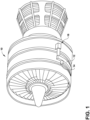
- FIG. 1 illustrates an engine 10 (e.g., a gas turbine engine) having an accessory gear box (AGB) 12 and an electric machine 14 according to an aspect of the disclosure.
- the engine 10 can be a turbofan engine, such as a General Electric GEnx or CF6 series engine, used in modern aviation, or it could be a variety of other known gas turbine engines such as a turboprop or turboshaft.
- the AGB 12 can be coupled to the engine 10 by way of a mechanical power take off 16.
- the type and specifics of the engine 10 are not germane to the disclosure and will not be described further herein.
- the electric machine 14 can include one or more of a generator, motor, starter/generator, of combination thereof, and is not limited to generator aspects that can provide electrical power.
- the electric machine 14 can operate in a power generation mode to provide power, or in a motor mode, wherein power is consumed to generate rotational force, such as propulsion.
- Non-limiting examples of the electric machine 14 can include synchronous or asynchronous machine architectures.
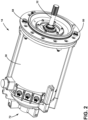
- the electric machine 14 can a housing 30 (e.g., a stator) and a rotor 32 disposed at least partially in the housing 30.
- the rotor 32 can be configured for coupling with AGB 12 ( FIG. 1 ) to cause rotation of the rotor 32. Rotation of the rotor 32 relative to the housing 30 can generate electrical power. Providing electrical power to the electric machine 14 can cause rotation of the rotor 32 relative to the housing 30.
- the rotor 32 is operably coupled with a mechanical power source, such as the engine 10 via the AGB 12 ( FIG. 1 ) operably coupled with the engine 10 via the power take off 16. For example, operation of the engine 10 can rotate one or more portions of the power take off 16 ( FIG. 1 ), which can rotate one or more portions of the AGB 12 ( FIG. 1 ), which can then rotate the rotor 32 to generate electrical power.
- the electric machine 14 includes a first inlet 50, a first outlet 52, a second inlet 56, and a second outlet 58.
- the housing 30 at least partially defines a first fluid passage 54 fluidly coupling the first inlet 50 and the first outlet 52, and a defines a second fluid passage 60 fluidly coupling the second inlet 56 and the second outlet 58.
- the housing 30 at least partially defines a chamber 70 (e.g., a fluid chamber).
- the first outlet 52 and the second inlet 56 are fluidly coupled with the chamber 70.
- the first inlet 50 and the second outlet 58 are fluidly coupled with an exterior of the housing 30.
- the housing 30 can include one or more electrical components 62, such as a plurality of coils.
- One or both of the first fluid passage 54 or the second fluid passage 60 can extend adjacent to, through, or both, the one or more electrical components 62, such as to cool the one or more electrical components 62, such as via the flow of a cooling fluid F.
- the housing 30 can include a cap 72 that can be connected to an end of the housing 30.
- the cap 72 can at least partially define the chamber 70, define a portion of the first fluid passage 54, at least partially receive a first nozzle 110, define a portion of the second fluid passage 60, define the second inlet 56, or a combination thereof.
- the cap 72 may be connected to other portions of the housing 30, such as after the rotor 32 is disposed in the housing 30.
- the rotor 32 includes a third inlet 80 and a third outlet 82.
- the rotor 32 at least partially defines a third fluid passage 84 fluidly coupling the third inlet 80 with the third outlet 82.
- the rotor 32 includes a rotor shaft 90 and a rotor body 92 coupled to rotate with the rotor shaft 90.
- the rotor shaft 90 can include one more electrical components 94, such as a rectifier, that can be disposed in, adjacent to, or both, the third fluid passage 84.
- the rotor body 92 can include, for example, one or more coils or windings 96.
- the third fluid passage 84 can include a first portion 100, a second portion 102, and a third portion 104.
- the first portion 100 can extends in the rotor shaft 90, such as from the second nozzle 112 and the third inlet 80 to the second portion 102.
- the second portion 102 can extend from the first portion 100 through the rotor body 92 to the third portion 104.
- the second portion 102 can extend adjacent to, through, or both, the one or more coils or windings 96.
- the third portion 104 can extend from the second portion 102 through the rotor shaft 90 to the third outlet 82, such as to one or more outlet portions 150 of the third outlet 82, which may be defined by the second nozzle 112.
- the third portion 104 can be disposed radially outward of the first portion 100.
- the third portion 104 can be disposed in the rotor shaft 90.
- the third fluid passage 84 can, for example, function as a fluid loop through the rotor 32.
- the electric machine 14 includes the first nozzle 110 and a second nozzle 112.
- the first nozzle 110 is coupled with the housing 30, defines the first outlet 52, and is fluidly coupled with the first fluid passage 54.
- the second nozzle 112 is coupled with the rotor 32, is at least partially aligned with the first nozzle 110, defines the third inlet 80, and is fluidly coupled with the third fluid passage 84.
- the first nozzle 110, the second nozzle 112, or both, can be partially disposed in the chamber 70.
- the first nozzle 110 is fluidly coupled with the second nozzle 112 via a non-contact interface 114.
- the second nozzle 112 can include a sleeve 120 disposed at least partially in the chamber 70 and a shoulder 122 disposed at an inner axial end of the sleeve 120.
- a portion of the first nozzle 110 can be disposed in the sleeve 120 such that a radial gap 124 is present between the inner surface of the sleeve 120 and the outer surface of the first nozzle 110, and such that the first nozzle 110 and the second nozzle 112 partially overlap in the radial direction.
- the axial end 128 of the first nozzle 110 (e.g., closest to the second nozzle 112) can be axially offset from the shoulder 122 such that an axial gap 126 is present between portions of the first nozzle 110 and the second nozzle 112.
- the first nozzle 110 can include a converging configuration in which the inner diameter (e.g., the hydraulic diameter) of the first nozzle 110 decreases toward the second nozzle 112.
- the second nozzle 112 can include a converging-diverging configuration in which the inner diameter (e.g., the hydraulic diameter) of the second nozzle 112 first decreases away from the first nozzle 110 and then increases.
- the electric machine 14 can include an impeller 140 that is disposed at least partially in the chamber 70.
- the impeller 140 can be coupled to or integrally formed with the rotor 32 such that the impeller 140 rotates with the rotor 32.
- the impeller 140 includes a set of impeller blades 142 that extend from an outer surface of the sleeve 120 and are disposed at least partially in the chamber 70.
- the impeller 140 can be disposed such that the impeller 140 (e.g., the set of impeller blades 142) and the first nozzle 110 at least partially overlap in the radial direction.
- the electric machine 14 can include a flow path 160 for fluid (e.g., the cooling fluid F) to flow through the electric machine 14, such as to cool one or more portions thereof.
- the flow path 160 can, for example, extend from the first inlet 50, through the first fluid passage 54 to the first nozzle 110 and the first outlet 52, across the non-contact interface 114 into the second nozzle 112 and the third inlet 80, through the first portion 100 and the rotor shaft 90, through the second portion 102 and the rotor body 92, through the third portion 104 to the third outlet 82, the outlet portions 150, and the second nozzle 112, into the chamber 70, into the second inlet 56, through the second fluid passage 60, and out of the housing 30 and the electric machine 14 to an exterior of the housing 30 through the second outlet 58.
- the flow path 160 can include other configurations, and may, for example, include portions of the AGB 12 (see, e.g., FIG. 8 ).
- first and second fluid passages 54, 60, and the corresponding first and second inlets 50, 56 and first and second outlets 52, 58 can be disposed at a variety of locations of the electric machine 14.
- the first fluid passage 54 can be disposed in a top half of the housing 30, the second fluid passage 60 can be disposed in a bottom half of the housing 30, or a combination thereof.
- the first fluid passage 54 can be disposed in the bottom half of the housing 30, the second fluid passage 60 can be disposed in the top half of the housing 30, or a combination thereof.
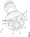
- the third outlet 82 can include a plurality of separate outlet portions 150 that can be circumferentially spaced, equally or unequally, at an axial surface 152 of the second nozzle 112.
- the outlet portions 150 can be fluidly coupled to the third fluid passage 84 ( FIG. 4 ).
- the set of impeller blades 142 can extend from the axial surface 152 and some or each of the plurality of outlet portions 150 can be disposed between respective adjacent pairs of the set of impeller blades 142.
- the set of impeller blades 142 can include eight impeller blades and the plurality of outlet portions 150 can include eight outlet portions.
- the set of impeller blades 142 can move the cooling fluid F in the chamber 70 ( FIG. 4 ), including the cooling fluid F exiting the third outlet 82 and the outlet portions 150 thereof.
- the set of impeller blades 142 can move the cooling fluid F in the chamber 70 ( FIG. 4 ) toward and into the second inlet 56 ( FIG. 4 ).
- the movement of the cooling fluid F caused by the set of impeller blades 142 can be sufficient to push the fluid through the second fluid passage 60 ( FIG. 4 ) to the second outlet 58 ( FIG. 4 ) and out of the electric machine 14 ( FIG. 4 ).
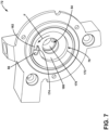
- the cap 72 can include a first recess 170 that partially defines the first fluid passage 54 and that at least partially receives the first nozzle 110 ( FIG. 4 ).
- the first recess 170 can, for example, be cylindrical, concentric with the rotor 32 ( FIG. 4 ), or both.
- the cap 72 can include a second recess 172.
- the first recess 170 may extend from the second recess 172 such that the first recess 170 is axially outward of the second recess 172 in an assembled configuration.
- the second recess 172 may at least partially define the chamber 70 such that some or all of the impeller 140 ( FIG.
- the second recess 172 can include a protrusion 174 that extends generally in the circumferential direction and separates a first portion 180 of the second recess 172 and a second portion 182 of the second recess 172.
- the protrusion 174 can function as a cutwater portion.
- the second portion 182 can be radially outward of the first portion 180 and can be fluidly coupled with the second inlet 56.
- the cooling fluid F that enters the chamber 70 may enter the first portion 180 of the second recess 172, the impeller 140 ( FIG. 4 ) may move the cooling fluid F within the first portion 180, and as the fluid contacts the protrusion 174, at least some of the fluid flows into the second portion 182 and into the second inlet 56.
- the second inlet 56 can, for example, be angled relative to (e.g., not parallel with) the circumferential direction, the axial direction, the radial direction, or a combination thereof.
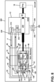
- FIG. 8 a schematic of an aircraft 200 is illustrated with the engine 10, the AGB 12, and the electric machine 14.
- the engine 10 can be coupled to the take off 16 to cause rotation of one or more portions of the AGB 12, such as a set of gears 210 of the AGB 12.
- the AGB 12 can rotate the rotor 32, such as via the set of gears 210.
- the AGB 12 can include a reservoir 212 for cooling fluid F and a pump 214 for cooling fluid F.
- the pump 214 can pump the cooling fluid F to the set of gears 210, to the electric machine 14, or both.
- the cooling fluid F provided to the set of gears 210 can cool, lubricate, or both, the set of gears 210.
- the pump 214 can be fluidly coupled with the electric machine 14, such as with the first inlet 50, the second outlet 58, or both.
- the AGB 12 can include a first AGB fluid passage 230 that is fluidly coupled with the pump 214, and operation of the pump 214 can provide fluid through the first AGB fluid passage 230 to the first inlet 50 and through the first fluid passage 54 to the first outlet 52 and the first nozzle 110.
- the fluid pressure or velocity provided via the pump 214 can be sufficient such that cooling fluid F that reaches and then exits the first nozzle 110 flows across the non-contact interface 114 (e.g., across the axial gap 126) and into the second nozzle 112.
- the cooling fluid F can continue to flow through the third fluid passage 84 and into the chamber 70.
- the impeller 140 can push the cooling fluid F into the second inlet 56, through the second fluid passage 60, and out of the electric machine 14 via the second outlet 58.
- the cooling fluid F may then flow into the AGB 12, such as into a second AGB fluid passage 232 fluidly coupled with the second fluid passage 60 via the second outlet 58.
- At least a portion of the cooling fluid F received in the second AGB fluid passage 232 can be provided to the set of gears 210 for lubrication.
- the cooling fluid F returning to the AGB 12 from the electric machine 14 can have a higher temperature than the cooling fluid F provided to the electric machine 14 (e.g., as a result of cooling portions of the electric machine 14), but the increased temperature may not materially affect the utility of the cooling fluid F for lubricating the AGB 12 (e.g., the set of gears 210).
- One or more other portions of the returned cooling fluid F can be provided to the reservoir 212 or other portions of the AGB 12, such as for cooling, lubrication, or a combination thereof.
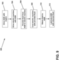
- the method 300 includes driving the AGB 12 with the engine 10 (block 302) and driving the electric machine 14 with the AGB 12 (block 304), such as to generate electrical power.
- the method 300 includes providing (e.g., pumping) cooling fluid F from the AGB 12 (block 306), such as from the reservoir 212 via the pump 214, to the electric machine 14, such as to the first inlet 50.
- the method 300 can include cooling the electric machine 14, such as one or more portions of the housing 30, the rotor 32, or both, with the cooling fluid F from the AGB 12 (block 308).
- the method 300 can include returning the cooling fluid F to the AGB 12 (block 310), such as via the impeller 140 pushing the cooling fluid F through the second fluid passage 60 and into the second AGB fluid passage 232.
- the method 300 can include lubricating the AGB 12 (block 312), such as with the cooling fluid F returned from the electric machine 14, cooling fluid F from the pump 214, or both.
- the aircraft 200 can include a controller 250 that can include a processor 252 and a memory 254, among other components.
- the controller 250 can be operably coupled with and/or at least partially control operation of the engine 10, the AGB 12, the electric machine 14, or a combination thereof.
- the controller 250 can control operation of the engine 10, the AGB 12, and the electric machine 14 to carry out the method 300, which can include operating the pump 214 to provide sufficient flow of the cooling fluid F to cool the electric machine 14 and lubricate the AGB 12 with the cooling fluid F returned from the electric machine 14.
- the electric machine 14 is a dry cavity machine. Additionally or alternatively, the electric machine 14, including the housing 30, is devoid of a pump.
- An engine assembly e.g., a gas turbine engine assembly
- the aircraft 200 can include the engine assembly.
- An electric machine comprising: a housing at least partially defining a chamber; a rotor disposed in the housing; and an impeller disposed at least partially in the chamber and coupled with the rotor.
- the housing at least partially defines a first fluid passage and a second fluid passage, the second fluid passage fluidly coupled with the chamber; wherein the rotor has a third fluid passage fluidly coupled with the chamber; and wherein the electric machine further comprises: a first nozzle coupled with the housing and fluidly coupled with the first fluid passage; a first outlet defined by the first nozzle; a first inlet fluidly coupled with the first fluid passage; a second inlet and a second outlet fluidly coupled with the second fluid passage; and a second nozzle coupled with the rotor, at least partially aligned with the first nozzle, and defining a third inlet fluidly coupled with the third fluid passage; wherein the first nozzle is fluidly coupled with the second nozzle via a non-contact interface.
- the first nozzle includes a converging configuration; and wherein the second nozzle includes a converging-diverging configuration.
- the second nozzle includes a sleeve disposed at least partially in the chamber; and a portion of the first nozzle is disposed in the sleeve.
- the impeller includes a set of blades extending from an outer surface of the sleeve and disposed in the chamber.
- the housing at least partially defines a first fluid passage and a second fluid passage, the second fluid passage fluidly coupled with the chamber; wherein the rotor has a third fluid passage fluidly coupled with the chamber; and wherein a fluid path extends through the first fluid passage to the third fluid passage, through the third fluid passage to the chamber, from the chamber to the second fluid passage, and from the second fluid passage to an exterior of the housing.
- the rotor includes a rectifier disposed in or adjacent to the third fluid passage.
- the housing at least partially defines a first fluid passage and a second fluid passage, the second fluid passage fluidly coupled with the chamber; wherein the rotor has a third fluid passage fluidly coupled with the chamber; and wherein the electric machine further comprises: a first inlet and a first outlet fluidly coupled with the first fluid passage; a second inlet and a second outlet fluidly coupled with the second fluid passage; and a third inlet and a third outlet fluidly coupled with the third fluid passage; wherein the rotor includes a rotor shaft and a rotor body coupled to the rotor shaft; wherein the third fluid passage includes a first portion, a second portion, and a third portion; wherein the first portion extends from the third inlet through the rotor shaft to the second portion; wherein the second portion extends through the rotor body to the third portion; and wherein the third portion extends from the second portion through the rotor shaft to the third outlet.
- the impeller includes a plurality of circumferentially spaced blades; and wherein the third outlet is disposed between an adjacent pair of the plurality of circumferentially spaced blades.
- impeller is mounted on or integrally formed with the rotor shaft; and the impeller is configured to push fluid into the second inlet and through the second fluid passage to an exterior of the housing.
- An assembly for an aircraft comprising: the electric machine of any preceding clause, the housing of the electric machine at least partially defining a first fluid passage; and an accessory gearbox (AGB) mechanically coupled to drive the electric machine, the AGB comprising: a pump; and an AGB fluid passage fluidly coupled with the pump; wherein the AGB fluid passage is fluidly coupled with the first fluid passage of the electric machine.
- AGB accessory gearbox
- the housing of the electric machine at least partially defines a second fluid passage
- the AGB includes a second AGB fluid passage fluidly coupled with the second fluid passage of the electric machine.
- a method of operating an aircraft comprising: driving an accessory gearbox (AGB) with an engine; driving an electric machine with the AGB; providing fluid from the AGB to the electric machine; cooling the electric machine with the fluid from the AGB; and returning the fluid from the electric machine to the AGB.
- AGB accessory gearbox
- returning the fluid from the electric machine to the AGB includes an impeller coupled to a rotor shaft of the electric machine pushing the fluid through a fluid passage of the electric machine.
- a gas turbine engine assembly comprising the electric machine of any preceding clause.
- a gas turbine engine assembly comprising the assembly of any preceding clause.
- An electronic controller including a processor and a memory, wherein the electronic controller is configured to conduct the method of any preceding clause.
- An electronic controller including a processor and a memory, wherein the electronic controller is configured to operate the electric machine of any preceding clause.
- An electronic controller including a processor and a memory, wherein the electronic controller is configured to operate the gas turbine engine of any preceding clause.
- operating the gas turbine engine includes driving an accessory gearbox (AGB) with an engine; driving an electric machine with the AGB; providing fluid from the AGB to the electric machine; cooling the electric machine with the fluid from the AGB; and returning the fluid from the electric machine to the AGB.
- AGB accessory gearbox
- operating the gas turbine engine includes lubricating the AGB with the fluid returned from the electric machine.
- returning the fluid from the electric machine to the AGB includes an impeller coupled to a rotor shaft of the electric machine pushing the fluid through a fluid passage of the electric machine.
- An electronic controller including a processor and a memory, wherein the electronic controller is configured to operate the assembly of any preceding clause.
- An electronic controller including a processor and a memory, wherein the electronic controller is configured to operate the aircraft of any preceding clause.
- a non-transitory computer readable medium comprising instructions that, when executed, cause a processor to conduct the method of any preceding clause.
- a non-transitory computer readable medium comprising instructions that, when executed, cause a processor to operate the electric machine of any preceding clause.
- a non-transitory computer readable medium comprising instructions that, when executed, cause a processor to operate the gas turbine engine of any preceding clause.
- a non-transitory computer readable medium comprising instructions that, when executed, cause a processor to operate the assembly of any preceding clause.
- a non-transitory computer readable medium comprising instructions that, when executed, cause a processor to operate the aircraft of any preceding clause.
- An aircraft comprising at least one of the electric machine, the electronic controller, the assembly, the gas turbine engine, or the non-transitory computer readable medium of any preceding clause.
- FIG. 1 illustrates non-limiting examples of electric machines and portions thereof, and additional components, such as power distribution nodes, converters, power protection components, and the like, can be included in the electrical machines, but are not shown or described, for brevity.
- aspects disclosed herein include an electrical machine with an induction generator and a converter in parallel, and the induction generator can switch between absorbing and supplementing the output of the induction generator output to compensate for changing power demands.
- the technical effect is that the above-described aspects enable faster responses to changing power demands via solid-state components of the converter.
Landscapes
- Engineering & Computer Science (AREA)
- Power Engineering (AREA)
- Mechanical Engineering (AREA)
- General Engineering & Computer Science (AREA)
- Motor Or Generator Cooling System (AREA)
- Connection Of Motors, Electrical Generators, Mechanical Devices, And The Like (AREA)
Abstract
An electric machine (14) comprises a housing (30) at least partially defining a chamber (70), a first fluid passage (54), and a second fluid passage (60), the second fluid passage (60) fluidly coupled with the chamber (70); a rotor (32) disposed in the housing (30) and having a third fluid passage (84) fluidly coupled with the chamber (70); and an impeller (140) disposed at least partially in the chamber (70) and coupled with the rotor (32).
Description
- The disclosure relates to a method and apparatus for operating an electrical machine and more specifically to operating the electrical machine in response to a varying power demand.
- Electrical machines, which can include electrical generators, are used in energy conversion. In the aircraft industry, an electrical machine can be mechanically coupled to a source of rotation, such as a mechanical or electrical machine, which for some aircraft may include a gas turbine engine. The generator can convert the mechanical energy of rotation into electrical energy.
- In the drawings:
-
FIG. 1 is a perspective view of an engine, an accessory gearbox (AGB), and an electrical machine, in accordance with various aspects described herein. -
FIG. 2 is a perspective view of an electrical machine in accordance with various aspects described herein. -
FIG. 3 is a cross-sectional view of an electrical machine in accordance with various aspects described herein. -
FIG. 4 is an enlarged portion ofFIG. 3 . -
FIG. 5 is a perspective view of a second nozzle of an electric machine in accordance with various aspects described herein. -
FIG. 6 is a cross-sectional perspective view of a second nozzle of an electric machine in accordance with various aspects described herein. -
FIG. 7 is a perspective view of a cap of an electric machine in accordance with various aspects described herein. -
FIG. 8 is a schematic view of an aircraft, including an engine, an accessory gearbox (AGB), and an electrical machine, in accordance with various aspects described herein. -
FIG. 9 is a flow diagram of a method of operating an aircraft in accordance with various aspects described herein. - Aspects of the present disclosure are described herein in the context of an electric machine of an aircraft, which enables production of electrical power from an energy source such as a turbine engine, jet fuel, hydrogen, batteries, etc. However, it will be understood that the disclosure is not so limited and has general applicability to power distribution systems or power generation systems in non-aircraft applications, including other mobile applications and non-mobile industrial, commercial, and residential applications. For example, applicable mobile environments can include an aircraft, spacecraft, space-launch vehicle, satellite, locomotive, automobile, etc. Commercial environments can include manufacturing facilities or power generation and distribution facilities or infrastructure.
- Electric machines can be designed, sized, or otherwise controllable to generate an estimated, determined, predicted, or otherwise expected amount or quantity of electrical power to provide to a set of electrical loads. It may be desirable to flow cooling fluid through one or more portions of the electrical machine to provide cooling. The size, the weight, or both, of the electric machine can be reduced relative to other designs by providing cooling fluid from an external source, such as a pump of an accessory gearbox (AGB) that may be operably and fluidly coupled with the electric machine.
- As used herein, the term "set" or a "set" of elements can be any number of elements, including only one.
- All directional references (e.g., radial, axial, upper, lower, upward, downward, left, right, lateral, front, back, top, bottom, above, below, vertical, horizontal, clockwise, counterclockwise) that may be used herein are only used for identification purposes to aid the reader's understanding of the disclosure, and do not create limitations, particularly as to the position, orientation, or use thereof. Connection references (e.g., attached, coupled, connected, and joined) are to be construed broadly and can include intermediate members between a collection of elements and relative movement between elements unless otherwise indicated. As such, connection references do not necessarily infer that two elements are directly connected and in fixed relation to each other. In non-limiting examples, connections or disconnections can be selectively configured to provide, enable, disable, or the like, an electrical connection between respective elements. Non-limiting example electric machine connections or disconnections can be enabled or operated by way of switching, bus tie logic, or any other connectors configured to enable or disable the energizing of electrical loads downstream of the bus. Additionally, as used herein, "electrical connection" or "electrically coupled" can include a wired or wireless connection, or both. The exemplary drawings are for purposes of illustration only and the dimensions, positions, order and relative sizes reflected in the drawings attached hereto can vary.
- A fluid passage can include various forms, including being integrally formed with another component (e.g., via an aperture in a housing, a shaft, etc.), provided in a separate component (e.g., a tube, a hose, a pipe, etc.), or a combination thereof.
- Additionally, as used herein, a "controller" or "controller module" can include a component configured or adapted to provide instruction, control, operation, or any form of communication for operable components to effect the operation thereof. A controller can include any known processor, microcontroller, or logic device, including, but not limited to: field programmable gate arrays (FPGA), an application specific integrated circuit (ASIC), a full authority digital engine control (FADEC), a proportional controller (P), a proportional integral controller (PI), a proportional derivative controller (PD), a proportional integral derivative controller (PID controller), proportional resonant controller (PR), a hardware-accelerated logic controller (e.g. for encoding, decoding, transcoding, etc.), the like, or a combination thereof. Non-limiting examples of a controller can be configured or adapted to run, operate, or otherwise execute program code to effect operational or functional outcomes, including carrying out various methods, functionality, processing tasks, calculations, comparisons, sensing or measuring of values, or the like, to enable or achieve the technical operations or operations described herein. The operation or functional outcomes can be based on one or more inputs, stored data values, sensed or measured values, true or false indications, or the like. While "program code" is described, non-limiting examples of operable or executable instruction sets can include routines, programs, objects, components, data structures, algorithms, etc., that have the technical effect of performing particular tasks or implement particular abstract data types. In another non-limiting example, a controller can also include a data storage component accessible by the processor, including memory, whether transient, volatile or non-transient, or non-volatile memory.
- Additional non-limiting examples of the memory can include Random Access Memory (RAM), Read-Only Memory (ROM), flash memory, or one or more different types of portable electronic memory, such as discs, DVDs, CD-ROMs, flash drives, universal serial bus (USB) drives, the like, or any suitable combination of these types of memory. In one example, the program code can be stored within the memory in a machine-readable format accessible by the processor. Additionally, the memory can store various data, data types, sensed or measured data values, inputs, generated or processed data, or the like, accessible by the processor in providing instruction, control, or operation to effect a functional or operable outcome, as described herein. In another non-limiting example, a controller can be configured for comparing a first value with a second value, and operating and controlling operations of additional components based on the satisfying of that comparison. For example, when a sensed, measured, or provided value is compared with another value, including a stored or predetermined value, the satisfaction of that comparison can result in actions, functions, or operations controllable by the controller. As used, the term "satisfies" or "satisfaction" of the comparison is used herein to mean that the first value satisfies the second value, such as being equal to or less than the second value, or being within the value range of the second value. It will be understood that such a determination may easily be altered to be satisfied by a positive/negative comparison or a true/false comparison. Example comparisons can include comparing a sensed or measured value to a threshold value or threshold value range.
- Here and throughout the specification and claims, range limitations are combined and interchanged, such ranges are identified and include all the sub-ranges contained therein unless context or language indicates otherwise. For example, all ranges disclosed herein are inclusive of the endpoints, and the endpoints are independently combinable with each other.
- Aspects of the disclosure can be implemented in any environment using an electric machine or power generator. Further, while this description is primarily directed toward an aircraft environment, aspects of the disclosure are applicable in any environment using an electrical machine.
- The exemplary drawings are for purposes of illustration only and the dimensions, positions, order and relative sizes reflected in the drawings attached hereto can vary.
-
FIG. 1 illustrates an engine 10 (e.g., a gas turbine engine) having an accessory gear box (AGB) 12 and anelectric machine 14 according to an aspect of the disclosure. Theengine 10 can be a turbofan engine, such as a General Electric GEnx or CF6 series engine, used in modern aviation, or it could be a variety of other known gas turbine engines such as a turboprop or turboshaft. The AGB 12 can be coupled to theengine 10 by way of a mechanical power take off 16. The type and specifics of theengine 10 are not germane to the disclosure and will not be described further herein. Theelectric machine 14 can include one or more of a generator, motor, starter/generator, of combination thereof, and is not limited to generator aspects that can provide electrical power. For instance, in one non-limiting example, theelectric machine 14 can operate in a power generation mode to provide power, or in a motor mode, wherein power is consumed to generate rotational force, such as propulsion. Non-limiting examples of theelectric machine 14 can include synchronous or asynchronous machine architectures. - Referring to
FIG. 2 , theelectric machine 14 can a housing 30 (e.g., a stator) and arotor 32 disposed at least partially in thehousing 30. Therotor 32 can be configured for coupling with AGB 12 (FIG. 1 ) to cause rotation of therotor 32. Rotation of therotor 32 relative to thehousing 30 can generate electrical power. Providing electrical power to theelectric machine 14 can cause rotation of therotor 32 relative to thehousing 30. Therotor 32 is operably coupled with a mechanical power source, such as theengine 10 via the AGB 12 (FIG. 1 ) operably coupled with theengine 10 via the power take off 16. For example, operation of theengine 10 can rotate one or more portions of the power take off 16 (FIG. 1 ), which can rotate one or more portions of the AGB 12 (FIG. 1 ), which can then rotate therotor 32 to generate electrical power. - As generally illustrated in
FIG. 3 , theelectric machine 14 includes afirst inlet 50, afirst outlet 52, asecond inlet 56, and asecond outlet 58. Thehousing 30 at least partially defines afirst fluid passage 54 fluidly coupling thefirst inlet 50 and thefirst outlet 52, and a defines asecond fluid passage 60 fluidly coupling thesecond inlet 56 and thesecond outlet 58. Thehousing 30 at least partially defines a chamber 70 (e.g., a fluid chamber). Thefirst outlet 52 and thesecond inlet 56 are fluidly coupled with thechamber 70. Thefirst inlet 50 and thesecond outlet 58 are fluidly coupled with an exterior of thehousing 30. Thehousing 30 can include one or moreelectrical components 62, such as a plurality of coils. One or both of thefirst fluid passage 54 or thesecond fluid passage 60 can extend adjacent to, through, or both, the one or moreelectrical components 62, such as to cool the one or moreelectrical components 62, such as via the flow of a cooling fluid F. - The
housing 30 can include acap 72 that can be connected to an end of thehousing 30. Thecap 72 can at least partially define thechamber 70, define a portion of thefirst fluid passage 54, at least partially receive afirst nozzle 110, define a portion of thesecond fluid passage 60, define thesecond inlet 56, or a combination thereof. Thecap 72 may be connected to other portions of thehousing 30, such as after therotor 32 is disposed in thehousing 30. - The
rotor 32 includes athird inlet 80 and athird outlet 82. Therotor 32 at least partially defines athird fluid passage 84 fluidly coupling thethird inlet 80 with thethird outlet 82. Therotor 32 includes arotor shaft 90 and arotor body 92 coupled to rotate with therotor shaft 90. Therotor shaft 90 can include one moreelectrical components 94, such as a rectifier, that can be disposed in, adjacent to, or both, thethird fluid passage 84. Therotor body 92 can include, for example, one or more coils orwindings 96. Thethird fluid passage 84 can include afirst portion 100, asecond portion 102, and athird portion 104. Thefirst portion 100 can extends in therotor shaft 90, such as from thesecond nozzle 112 and thethird inlet 80 to thesecond portion 102. Thesecond portion 102 can extend from thefirst portion 100 through therotor body 92 to thethird portion 104. For example, thesecond portion 102 can extend adjacent to, through, or both, the one or more coils orwindings 96. Thethird portion 104 can extend from thesecond portion 102 through therotor shaft 90 to thethird outlet 82, such as to one ormore outlet portions 150 of thethird outlet 82, which may be defined by thesecond nozzle 112. Thethird portion 104 can be disposed radially outward of thefirst portion 100. Thethird portion 104 can be disposed in therotor shaft 90. Thethird fluid passage 84 can, for example, function as a fluid loop through therotor 32. - The
electric machine 14 includes thefirst nozzle 110 and asecond nozzle 112. Thefirst nozzle 110 is coupled with thehousing 30, defines thefirst outlet 52, and is fluidly coupled with thefirst fluid passage 54. Thesecond nozzle 112 is coupled with therotor 32, is at least partially aligned with thefirst nozzle 110, defines thethird inlet 80, and is fluidly coupled with thethird fluid passage 84. Thefirst nozzle 110, thesecond nozzle 112, or both, can be partially disposed in thechamber 70. - Referring to
FIG. 4 , thefirst nozzle 110 is fluidly coupled with thesecond nozzle 112 via anon-contact interface 114. For example, thesecond nozzle 112 can include asleeve 120 disposed at least partially in thechamber 70 and ashoulder 122 disposed at an inner axial end of thesleeve 120. A portion of thefirst nozzle 110 can be disposed in thesleeve 120 such that aradial gap 124 is present between the inner surface of thesleeve 120 and the outer surface of thefirst nozzle 110, and such that thefirst nozzle 110 and thesecond nozzle 112 partially overlap in the radial direction. Additionally or alternatively, theaxial end 128 of the first nozzle 110 (e.g., closest to the second nozzle 112) can be axially offset from theshoulder 122 such that anaxial gap 126 is present between portions of thefirst nozzle 110 and thesecond nozzle 112. Thefirst nozzle 110 can include a converging configuration in which the inner diameter (e.g., the hydraulic diameter) of thefirst nozzle 110 decreases toward thesecond nozzle 112. Thesecond nozzle 112 can include a converging-diverging configuration in which the inner diameter (e.g., the hydraulic diameter) of thesecond nozzle 112 first decreases away from thefirst nozzle 110 and then increases. - The
electric machine 14 can include animpeller 140 that is disposed at least partially in thechamber 70. Theimpeller 140 can be coupled to or integrally formed with therotor 32 such that theimpeller 140 rotates with therotor 32. Theimpeller 140 includes a set ofimpeller blades 142 that extend from an outer surface of thesleeve 120 and are disposed at least partially in thechamber 70. Theimpeller 140 can be disposed such that the impeller 140 (e.g., the set of impeller blades 142) and thefirst nozzle 110 at least partially overlap in the radial direction. - The
electric machine 14 can include aflow path 160 for fluid (e.g., the cooling fluid F) to flow through theelectric machine 14, such as to cool one or more portions thereof. Theflow path 160 can, for example, extend from thefirst inlet 50, through thefirst fluid passage 54 to thefirst nozzle 110 and thefirst outlet 52, across thenon-contact interface 114 into thesecond nozzle 112 and thethird inlet 80, through thefirst portion 100 and therotor shaft 90, through thesecond portion 102 and therotor body 92, through thethird portion 104 to thethird outlet 82, theoutlet portions 150, and thesecond nozzle 112, into thechamber 70, into thesecond inlet 56, through thesecond fluid passage 60, and out of thehousing 30 and theelectric machine 14 to an exterior of thehousing 30 through thesecond outlet 58. Theflow path 160 can include other configurations, and may, for example, include portions of the AGB 12 (see, e.g.,FIG. 8 ). - While the
first fluid passage 54 is shown toward the top of the page and thesecond fluid passage 60 is shown toward the bottom of the page inFIGS. 3 and4 , the first and secondfluid passages second inlets second outlets electric machine 14. For example and without limitation, in some configurations, thefirst fluid passage 54 can be disposed in a top half of thehousing 30, thesecond fluid passage 60 can be disposed in a bottom half of thehousing 30, or a combination thereof. In some other configurations, thefirst fluid passage 54 can be disposed in the bottom half of thehousing 30, thesecond fluid passage 60 can be disposed in the top half of thehousing 30, or a combination thereof. - Referring to
FIGS. 5 and6 , perspective and cross-sectional views, respectively, illustrate an example of thesecond nozzle 112. Thethird outlet 82 can include a plurality ofseparate outlet portions 150 that can be circumferentially spaced, equally or unequally, at anaxial surface 152 of thesecond nozzle 112. Theoutlet portions 150 can be fluidly coupled to the third fluid passage 84 (FIG. 4 ). The set ofimpeller blades 142 can extend from theaxial surface 152 and some or each of the plurality ofoutlet portions 150 can be disposed between respective adjacent pairs of the set ofimpeller blades 142. For example and without limitation, the set ofimpeller blades 142 can include eight impeller blades and the plurality ofoutlet portions 150 can include eight outlet portions. As theimpeller 140 rotates with the rotor 32 (FIG. 4 ), the set ofimpeller blades 142 can move the cooling fluid F in the chamber 70 (FIG. 4 ), including the cooling fluid F exiting thethird outlet 82 and theoutlet portions 150 thereof. For example, the set ofimpeller blades 142 can move the cooling fluid F in the chamber 70 (FIG. 4 ) toward and into the second inlet 56 (FIG. 4 ). The movement of the cooling fluid F caused by the set ofimpeller blades 142 can be sufficient to push the fluid through the second fluid passage 60 (FIG. 4 ) to the second outlet 58 (FIG. 4 ) and out of the electric machine 14 (FIG. 4 ). - Referring to
FIG. 7 , a perspective view of thecap 72 is provided. Thecap 72 can include afirst recess 170 that partially defines thefirst fluid passage 54 and that at least partially receives the first nozzle 110 (FIG. 4 ). Thefirst recess 170 can, for example, be cylindrical, concentric with the rotor 32 (FIG. 4 ), or both. Thecap 72 can include asecond recess 172. Thefirst recess 170 may extend from thesecond recess 172 such that thefirst recess 170 is axially outward of thesecond recess 172 in an assembled configuration. Thesecond recess 172 may at least partially define thechamber 70 such that some or all of the impeller 140 (FIG. 4 ) can be disposed in thesecond recess 172, in the assembled configuration. For example, a minimum inner diameter of thesecond recess 172 can be larger than the outer diameter of the impeller 140 (FIG. 4 ). Thesecond recess 172 can include aprotrusion 174 that extends generally in the circumferential direction and separates afirst portion 180 of thesecond recess 172 and asecond portion 182 of thesecond recess 172. For example, theprotrusion 174 can function as a cutwater portion. Thesecond portion 182 can be radially outward of thefirst portion 180 and can be fluidly coupled with thesecond inlet 56. In some implementations, the cooling fluid F that enters thechamber 70 may enter thefirst portion 180 of thesecond recess 172, the impeller 140 (FIG. 4 ) may move the cooling fluid F within thefirst portion 180, and as the fluid contacts theprotrusion 174, at least some of the fluid flows into thesecond portion 182 and into thesecond inlet 56. Thesecond inlet 56 can, for example, be angled relative to (e.g., not parallel with) the circumferential direction, the axial direction, the radial direction, or a combination thereof. - Referring to
FIG. 8 , a schematic of anaircraft 200 is illustrated with theengine 10, theAGB 12, and theelectric machine 14. Theengine 10 can be coupled to the take off 16 to cause rotation of one or more portions of theAGB 12, such as a set ofgears 210 of theAGB 12. TheAGB 12 can rotate therotor 32, such as via the set ofgears 210. TheAGB 12 can include areservoir 212 for cooling fluid F and apump 214 for cooling fluid F. Thepump 214 can pump the cooling fluid F to the set ofgears 210, to theelectric machine 14, or both. The cooling fluid F provided to the set ofgears 210 can cool, lubricate, or both, the set ofgears 210. - The
pump 214 can be fluidly coupled with theelectric machine 14, such as with thefirst inlet 50, thesecond outlet 58, or both. For example, theAGB 12 can include a firstAGB fluid passage 230 that is fluidly coupled with thepump 214, and operation of thepump 214 can provide fluid through the firstAGB fluid passage 230 to thefirst inlet 50 and through thefirst fluid passage 54 to thefirst outlet 52 and thefirst nozzle 110. The fluid pressure or velocity provided via thepump 214 can be sufficient such that cooling fluid F that reaches and then exits thefirst nozzle 110 flows across the non-contact interface 114 (e.g., across the axial gap 126) and into thesecond nozzle 112. The cooling fluid F can continue to flow through thethird fluid passage 84 and into thechamber 70. Theimpeller 140 can push the cooling fluid F into thesecond inlet 56, through thesecond fluid passage 60, and out of theelectric machine 14 via thesecond outlet 58. The cooling fluid F may then flow into theAGB 12, such as into a secondAGB fluid passage 232 fluidly coupled with thesecond fluid passage 60 via thesecond outlet 58. At least a portion of the cooling fluid F received in the secondAGB fluid passage 232 can be provided to the set ofgears 210 for lubrication. The cooling fluid F returning to theAGB 12 from theelectric machine 14 can have a higher temperature than the cooling fluid F provided to the electric machine 14 (e.g., as a result of cooling portions of the electric machine 14), but the increased temperature may not materially affect the utility of the cooling fluid F for lubricating the AGB 12 (e.g., the set of gears 210). One or more other portions of the returned cooling fluid F can be provided to thereservoir 212 or other portions of theAGB 12, such as for cooling, lubrication, or a combination thereof. - Referring to
FIG. 9 , amethod 300 of operating an aircraft, such as theaircraft 200 with theengine 10, theAGB 12, and theelectric machine 14 ofFIG. 8 , is illustrated. Themethod 300 includes driving theAGB 12 with the engine 10 (block 302) and driving theelectric machine 14 with the AGB 12 (block 304), such as to generate electrical power. Themethod 300 includes providing (e.g., pumping) cooling fluid F from the AGB 12 (block 306), such as from thereservoir 212 via thepump 214, to theelectric machine 14, such as to thefirst inlet 50. Themethod 300 can include cooling theelectric machine 14, such as one or more portions of thehousing 30, therotor 32, or both, with the cooling fluid F from the AGB 12 (block 308). Themethod 300 can include returning the cooling fluid F to the AGB 12 (block 310), such as via theimpeller 140 pushing the cooling fluid F through thesecond fluid passage 60 and into the secondAGB fluid passage 232. Themethod 300 can include lubricating the AGB 12 (block 312), such as with the cooling fluid F returned from theelectric machine 14, cooling fluid F from thepump 214, or both. - Referring again to
FIG. 8 , theaircraft 200 can include acontroller 250 that can include aprocessor 252 and amemory 254, among other components. Thecontroller 250 can be operably coupled with and/or at least partially control operation of theengine 10, theAGB 12, theelectric machine 14, or a combination thereof. For example, thecontroller 250 can control operation of theengine 10, theAGB 12, and theelectric machine 14 to carry out themethod 300, which can include operating thepump 214 to provide sufficient flow of the cooling fluid F to cool theelectric machine 14 and lubricate theAGB 12 with the cooling fluid F returned from theelectric machine 14. - With some implementations, the
electric machine 14 is a dry cavity machine. Additionally or alternatively, theelectric machine 14, including thehousing 30, is devoid of a pump. An engine assembly (e.g., a gas turbine engine assembly) can include theengine 10, theAGB 12, and theelectric machine 14. Theaircraft 200 can include the engine assembly. - Further aspects of the disclosure are provided by the subject matter of the following clauses:
- An electric machine, comprising: a housing at least partially defining a chamber; a rotor disposed in the housing; and an impeller disposed at least partially in the chamber and coupled with the rotor.
- The electric machine of any preceding clause wherein the housing at least partially defines a first fluid passage and a second fluid passage, the second fluid passage fluidly coupled with the chamber; wherein the rotor has a third fluid passage fluidly coupled with the chamber; and wherein the electric machine further comprises: a first nozzle coupled with the housing and fluidly coupled with the first fluid passage; a first outlet defined by the first nozzle; a first inlet fluidly coupled with the first fluid passage; a second inlet and a second outlet fluidly coupled with the second fluid passage; and a second nozzle coupled with the rotor, at least partially aligned with the first nozzle, and defining a third inlet fluidly coupled with the third fluid passage; wherein the first nozzle is fluidly coupled with the second nozzle via a non-contact interface.
- The electric machine of any preceding clause, wherein the first nozzle and the second nozzle partially overlap in a radial direction.
- The electric machine of any preceding clause, wherein the first nozzle and the impeller partially overlap in the radial direction.
- The electric machine of any preceding clause, wherein the first nozzle includes a converging configuration; and wherein the second nozzle includes a converging-diverging configuration.
- The electric machine of any preceding clause, wherein the second nozzle includes a sleeve disposed at least partially in the chamber; and a portion of the first nozzle is disposed in the sleeve.
- The electric machine of any preceding clause, wherein the impeller includes a set of blades extending from an outer surface of the sleeve and disposed in the chamber.
- The electric machine of any preceding clause, wherein the housing at least partially defines a first fluid passage and a second fluid passage, the second fluid passage fluidly coupled with the chamber; wherein the rotor has a third fluid passage fluidly coupled with the chamber; and wherein a fluid path extends through the first fluid passage to the third fluid passage, through the third fluid passage to the chamber, from the chamber to the second fluid passage, and from the second fluid passage to an exterior of the housing.
- The electric machine of any preceding clause, wherein the rotor includes a rectifier disposed in or adjacent to the third fluid passage.
- The electric machine of any preceding clause, further comprising a plurality of coils disposed in the housing; wherein the first fluid passage extends adjacent to the plurality of coils.
- The electric machine of any preceding clause, wherein the housing at least partially defines a first fluid passage and a second fluid passage, the second fluid passage fluidly coupled with the chamber; wherein the rotor has a third fluid passage fluidly coupled with the chamber; and wherein the electric machine further comprises: a first inlet and a first outlet fluidly coupled with the first fluid passage; a second inlet and a second outlet fluidly coupled with the second fluid passage; and a third inlet and a third outlet fluidly coupled with the third fluid passage; wherein the rotor includes a rotor shaft and a rotor body coupled to the rotor shaft; wherein the third fluid passage includes a first portion, a second portion, and a third portion; wherein the first portion extends from the third inlet through the rotor shaft to the second portion; wherein the second portion extends through the rotor body to the third portion; and wherein the third portion extends from the second portion through the rotor shaft to the third outlet.
- The electric machine of any preceding clause, wherein the third portion is disposed radially outward of the first portion.
- The electric machine of any preceding clause, wherein the impeller includes a plurality of circumferentially spaced blades; and wherein the third outlet is disposed between an adjacent pair of the plurality of circumferentially spaced blades.
- The electric machine of any preceding clause, wherein the impeller is mounted on or integrally formed with the rotor shaft; and the impeller is configured to push fluid into the second inlet and through the second fluid passage to an exterior of the housing.
- The electric machine of any preceding clause, wherein the housing is devoid of a pump.
- An assembly for an aircraft, the assembly comprising: the electric machine of any preceding clause, the housing of the electric machine at least partially defining a first fluid passage; and an accessory gearbox (AGB) mechanically coupled to drive the electric machine, the AGB comprising: a pump; and an AGB fluid passage fluidly coupled with the pump; wherein the AGB fluid passage is fluidly coupled with the first fluid passage of the electric machine.
- The assembly of any preceding clause, wherein the housing of the electric machine at least partially defines a second fluid passage the AGB includes a second AGB fluid passage fluidly coupled with the second fluid passage of the electric machine.
- A method of operating an aircraft, the method comprising: driving an accessory gearbox (AGB) with an engine; driving an electric machine with the AGB; providing fluid from the AGB to the electric machine; cooling the electric machine with the fluid from the AGB; and returning the fluid from the electric machine to the AGB.
- The method of any preceding clause, further comprising lubricating the AGB with the fluid returned from the electric machine.
- The method of any preceding clause, wherein returning the fluid from the electric machine to the AGB includes an impeller coupled to a rotor shaft of the electric machine pushing the fluid through a fluid passage of the electric machine.
- The electric machine of any preceding clause, wherein the electric machine is a dry cavity machine.
- A gas turbine engine assembly comprising the electric machine of any preceding clause.
- A gas turbine engine assembly comprising the assembly of any preceding clause.
- An aircraft comprising the electric machine of any preceding clause.
- An aircraft comprising the gas turbine engine assembly of any preceding clause.
- An electronic controller including a processor and a memory, wherein the electronic controller is configured to conduct the method of any preceding clause.
- An electronic controller including a processor and a memory, wherein the electronic controller is configured to operate the electric machine of any preceding clause.
- An electronic controller including a processor and a memory, wherein the electronic controller is configured to operate the gas turbine engine of any preceding clause.
- The electronic controller of any preceding clause, wherein operating the gas turbine engine includes driving an accessory gearbox (AGB) with an engine; driving an electric machine with the AGB; providing fluid from the AGB to the electric machine; cooling the electric machine with the fluid from the AGB; and returning the fluid from the electric machine to the AGB.
- The electronic controller of any preceding clause, wherein operating the gas turbine engine includes lubricating the AGB with the fluid returned from the electric machine.
- The electronic controller of any preceding clause, wherein returning the fluid from the electric machine to the AGB includes an impeller coupled to a rotor shaft of the electric machine pushing the fluid through a fluid passage of the electric machine.
- An electronic controller including a processor and a memory, wherein the electronic controller is configured to operate the assembly of any preceding clause.
- An electronic controller including a processor and a memory, wherein the electronic controller is configured to operate the aircraft of any preceding clause.
- A non-transitory computer readable medium comprising instructions that, when executed, cause a processor to conduct the method of any preceding clause.
- A non-transitory computer readable medium comprising instructions that, when executed, cause a processor to operate the electric machine of any preceding clause.
- A non-transitory computer readable medium comprising instructions that, when executed, cause a processor to operate the gas turbine engine of any preceding clause.
- A non-transitory computer readable medium comprising instructions that, when executed, cause a processor to operate the assembly of any preceding clause.
- A non-transitory computer readable medium comprising instructions that, when executed, cause a processor to operate the aircraft of any preceding clause.
- An aircraft comprising at least one of the electric machine, the electronic controller, the assembly, the gas turbine engine, or the non-transitory computer readable medium of any preceding clause.
- While aspects of the disclosure are shown in an aircraft environment, the disclosure is not so limited and can have applicability in a variety of environments.
- The drawings illustrate non-limiting examples of electric machines and portions thereof, and additional components, such as power distribution nodes, converters, power protection components, and the like, can be included in the electrical machines, but are not shown or described, for brevity.
- The sequences described in this disclosure are for understanding purposes only and is not meant to limit aspects of the disclosure or the applicable methods of applying aspects of the disclosure in any way as it is understood that the portions of the method can proceed in a different logical order, additional or intervening portions can be included, or described portions of the method can be divided into multiple portions, or described portions of the method can be omitted without detracting from the described method.
- Many other possible aspects and configurations in addition to that shown in the above figures are contemplated by the present disclosure. Aspects disclosed herein include an electrical machine with an induction generator and a converter in parallel, and the induction generator can switch between absorbing and supplementing the output of the induction generator output to compensate for changing power demands. The technical effect is that the above-described aspects enable faster responses to changing power demands via solid-state components of the converter.
- To the extent not already described, the different features and structures of the various aspects can be used in combination with each other as desired. That one feature is not illustrated in all of the aspects is not meant to be construed that it cannot be, but is done for brevity of description. Thus, the various features of the different aspects can be mixed and matched as desired to form new aspects, whether or not the new aspects are expressly described. Combinations or permutations of features described herein are covered by this disclosure.
- This written description uses examples to disclose aspects of the disclosure, including the best mode, and also to enable any person skilled in the art to practice aspects of the disclosure, including making and using any devices or systems and performing any incorporated methods. The patentable scope of the disclosure is defined by the claims, and can include other examples that occur to those skilled in the art. Such other examples are intended to be within the scope of the claims if they have structural elements that do not differ from the literal language of the claims, or if they include equivalent structural elements with insubstantial differences from the literal languages of the claims.
- The various features of the different aspects can be mixed and matched as desired to form new aspects, whether or not the new aspects are expressly described. Combinations or permutations of features described herein are covered by this disclosure.
Claims (15)
- An electric machine (14), comprising:a housing (30) at least partially defining a chamber (70);a rotor (32) disposed in the housing (30); andan impeller (140) disposed at least partially in the chamber (70) and coupled with the rotor (32).
- The electric machine (14) of claim 1, wherein the housing at least partially defines a first fluid passage (54) and a second fluid passage (60), the second fluid passage (60) fluidly coupled with the chamber (70);wherein the rotor has a third fluid passage (84) fluidly coupled with the chamber (70); andwherein the electric machine further comprises:
a first nozzle (110) coupled with the housing (30) and fluidly coupled with the first fluid passage (54);a first outlet (52) defined by the first nozzle (110);a first inlet (50) fluidly coupled with the first fluid passage (54);a second inlet (56) and a second outlet (58) fluidly coupled with the second fluid passage (60); anda second nozzle (112) coupled with the rotor (32), at least partially aligned with the first nozzle (110), and defining a third inlet (80) fluidly coupled with the third fluid passage (84);wherein the first nozzle (110) is fluidly coupled with the second nozzle (112) via a non-contact interface. - The electric machine (14) of claim 2, wherein the first nozzle (110) and the second nozzle (112) partially overlap in a radial direction.
- The electric machine (14) of claim 3 or 4, wherein the first nozzle (110) and the impeller (140) partially overlap in the radial direction.
- The electric machine (14) of any of claims 2 to 4, wherein the first nozzle (110) includes a converging configuration; and
wherein the second nozzle (112) includes a converging-diverging configuration. - The electric machine (14) of any of claims 2 to 5, wherein the second nozzle (112) includes a sleeve (120) disposed at least partially in the chamber (70); and
a portion of the first nozzle (110) is disposed in the sleeve (120). - The electric machine (14) of claim 6, wherein the impeller (140) includes a set of blades extending from an outer surface of the sleeve (120) and disposed in the chamber (70).
- The electric machine (14) of any preceding claim, wherein the housing at least partially defines a first fluid passage (54) and a second fluid passage (60), the second fluid passage (60) fluidly coupled with the chamber (70);wherein the rotor has a third fluid passage (84) fluidly coupled with the chamber (70); andwherein a fluid path extends through the first fluid passage (54) to the third fluid passage (84), through the third fluid passage (84) to the chamber (70), from the chamber (70) to the second fluid passage (60), and from the second fluid passage (60) to an exterior of the housing (30).
- The electric machine (14) of claim 8, wherein the rotor (32) includes a rectifier disposed in or adjacent to the third fluid passage (84).
- The electric machine (14) of claim 9, further comprising a plurality of coils disposed in the housing (30);
wherein the first fluid passage (54) extends adjacent to the plurality of coils. - The electric machine (14) of any preceding claim, wherein the housing at least partially defines a first fluid passage (54) and a second fluid passage (60), the second fluid passage (60) fluidly coupled with the chamber (70);wherein the rotor has a third fluid passage (84) fluidly coupled with the chamber (70); andwherein the electric machine (14) further comprises:a first inlet (50) and a first outlet (52) fluidly coupled with the first fluid passage (54);a second inlet (56) and a second outlet (58) fluidly coupled with the second fluid passage (60); anda third inlet (80) and a third outlet (82) fluidly coupled with the third fluid passage (84);wherein the rotor (32) includes a rotor (32) shaft and a rotor (32) body coupled to the rotor (32) shaft;wherein the third fluid passage (84) includes a first portion (100), a second portion (102), and a third portion (104);wherein the first portion (100) extends from the third inlet (80) through the rotor (32) shaft to the second portion (102);wherein the second portion (102) extends through the rotor (32) body to the third portion (104); andwherein the third portion (104) extends from the second portion (102) through the rotor (32) shaft to the third outlet (82).
- The electric machine (14) of claim 11, wherein the third portion (104) is disposed radially outward of the first portion (100).
- The electric machine (14) of claim 11 or 12, wherein the impeller (140) includes a plurality of circumferentially spaced blades; and
wherein the third outlet (82) is disposed between an adjacent pair of the plurality of circumferentially spaced blades. - The electric machine (14) of claim 13, wherein the impeller (140) is mounted on or integrally formed with the rotor (32) shaft; and
the impeller (140) is configured to push fluid into the second inlet (56) and through the second fluid passage (60) to an exterior of the housing (30). - The electric machine (14) of any preceding claim, wherein the housing (30) is devoid of a pump (214).
Applications Claiming Priority (1)
| Application Number | Priority Date | Filing Date | Title |
|---|---|---|---|
| US18/536,925 US20250192642A1 (en) | 2023-12-12 | 2023-12-12 | Electric machine and method of operating aircraft |
Publications (1)
| Publication Number | Publication Date |
|---|---|
| EP4571055A1 true EP4571055A1 (en) | 2025-06-18 |
Family
ID=93379214
Family Applications (1)
| Application Number | Title | Priority Date | Filing Date |
|---|---|---|---|
| EP24210680.5A Pending EP4571055A1 (en) | 2023-12-12 | 2024-11-04 | Electric machine with cooling passages |
Country Status (3)
| Country | Link |
|---|---|
| US (1) | US20250192642A1 (en) |
| EP (1) | EP4571055A1 (en) |
| CN (1) | CN120150415A (en) |
Citations (4)
| Publication number | Priority date | Publication date | Assignee | Title |
|---|---|---|---|---|
| US8395288B2 (en) * | 2005-09-21 | 2013-03-12 | Calnetix Technologies, L.L.C. | Electric machine with centrifugal impeller |
| US20150288255A1 (en) * | 2012-10-09 | 2015-10-08 | Integral Powertrain Ltd. | Rotary device, a motor and a method of cooling a motor |
| US11002191B2 (en) * | 2019-01-04 | 2021-05-11 | Ge Aviation Systems Llc | Electric machine with non-contact interface |
| CN114069938A (en) * | 2020-07-29 | 2022-02-18 | 株洲中车时代电气股份有限公司 | Water-gas composite cooling motor structure and new energy automobile using same |
Family Cites Families (1)
| Publication number | Priority date | Publication date | Assignee | Title |
|---|---|---|---|---|
| JP5939351B2 (en) * | 2013-02-15 | 2016-06-22 | 日産自動車株式会社 | Cooling device for motor drive unit |
-
2023
- 2023-12-12 US US18/536,925 patent/US20250192642A1/en active Pending
-
2024
- 2024-11-04 EP EP24210680.5A patent/EP4571055A1/en active Pending
- 2024-12-03 CN CN202411758431.4A patent/CN120150415A/en active Pending
Patent Citations (4)
| Publication number | Priority date | Publication date | Assignee | Title |
|---|---|---|---|---|
| US8395288B2 (en) * | 2005-09-21 | 2013-03-12 | Calnetix Technologies, L.L.C. | Electric machine with centrifugal impeller |
| US20150288255A1 (en) * | 2012-10-09 | 2015-10-08 | Integral Powertrain Ltd. | Rotary device, a motor and a method of cooling a motor |
| US11002191B2 (en) * | 2019-01-04 | 2021-05-11 | Ge Aviation Systems Llc | Electric machine with non-contact interface |
| CN114069938A (en) * | 2020-07-29 | 2022-02-18 | 株洲中车时代电气股份有限公司 | Water-gas composite cooling motor structure and new energy automobile using same |
Also Published As
| Publication number | Publication date |
|---|---|
| US20250192642A1 (en) | 2025-06-12 |
| CN120150415A (en) | 2025-06-13 |
Similar Documents
| Publication | Publication Date | Title |
|---|---|---|
| CN108928493B (en) | Propulsion system for aircraft and method for operating same | |
| EP3023601B1 (en) | Tail cone generator with integral speed increasing gearbox | |
| RU2321761C2 (en) | Auxiliary equipment drive | |
| US8198744B2 (en) | Integrated boost cavity ring generator for turbofan and turboshaft engines | |
| CN115370480B (en) | AC power system for a vehicle | |
| CN109209642B (en) | Electrical machine | |
| CN113251111B (en) | Gearbox assembly with motor | |
| US20220003128A1 (en) | Dual rotor electric machine | |
| US10348162B1 (en) | Method and assembly of an electric machine | |
| EP4174298B1 (en) | Hybrid-electric single engine descent engine management | |
| EP3452709A1 (en) | Gas turbine power generation system with a high pressure compressor and an added forward low pressure compressor | |
| US12168519B2 (en) | Hybrid-electric single engine descent failure management | |
| EP4023872B1 (en) | Gas turbine engine | |
| CN113054796A (en) | Starter/generator system | |
| US11894738B2 (en) | Turbomachine equipped with an embedded electric machine having a segmented and movable stator | |
| US20230095723A1 (en) | Turbine engine with variable pitch fan | |
| US20250192642A1 (en) | Electric machine and method of operating aircraft | |
| US12525835B2 (en) | Rotor assembly for an electrical machine | |
| CN117469028A (en) | thermal management system | |
| EP3159543B1 (en) | Gear pump | |
| US20230184175A1 (en) | Systems and methods for aligning a gearbox of a gas turbine engine | |
| US12341428B2 (en) | Method and power distribution system for generating electrical power | |
| EP4498580A1 (en) | Air-cooled electric machine | |
| CN114645741B (en) | System and method for mitigating bent rotors in gas turbine engines | |
| RU2614421C1 (en) | Birotating compressor |
Legal Events
| Date | Code | Title | Description |
|---|---|---|---|
| PUAI | Public reference made under article 153(3) epc to a published international application that has entered the european phase |
Free format text: ORIGINAL CODE: 0009012 |
|
| STAA | Information on the status of an ep patent application or granted ep patent |
Free format text: STATUS: THE APPLICATION HAS BEEN PUBLISHED |
|
| AK | Designated contracting states |
Kind code of ref document: A1 Designated state(s): AL AT BE BG CH CY CZ DE DK EE ES FI FR GB GR HR HU IE IS IT LI LT LU LV MC ME MK MT NL NO PL PT RO RS SE SI SK SM TR |
|
| STAA | Information on the status of an ep patent application or granted ep patent |
Free format text: STATUS: REQUEST FOR EXAMINATION WAS MADE |
|
| 17P | Request for examination filed |
Effective date: 20251211 |