EP4571053A1 - Integrated centrigual compressor diffuser and high pressure turbine vane assembly - Google Patents
Integrated centrigual compressor diffuser and high pressure turbine vane assembly Download PDFInfo
- Publication number
- EP4571053A1 EP4571053A1 EP24218867.0A EP24218867A EP4571053A1 EP 4571053 A1 EP4571053 A1 EP 4571053A1 EP 24218867 A EP24218867 A EP 24218867A EP 4571053 A1 EP4571053 A1 EP 4571053A1
- Authority
- EP
- European Patent Office
- Prior art keywords
- combustor
- vane
- path
- section
- gas turbine
- Prior art date
- Legal status (The legal status is an assumption and is not a legal conclusion. Google has not performed a legal analysis and makes no representation as to the accuracy of the status listed.)
- Pending
Links
Images



Classifications
-
- F—MECHANICAL ENGINEERING; LIGHTING; HEATING; WEAPONS; BLASTING
- F01—MACHINES OR ENGINES IN GENERAL; ENGINE PLANTS IN GENERAL; STEAM ENGINES
- F01D—NON-POSITIVE DISPLACEMENT MACHINES OR ENGINES, e.g. STEAM TURBINES
- F01D9/00—Stators
- F01D9/02—Nozzles; Nozzle boxes; Stator blades; Guide conduits, e.g. individual nozzles
- F01D9/04—Nozzles; Nozzle boxes; Stator blades; Guide conduits, e.g. individual nozzles forming ring or sector
-
- F—MECHANICAL ENGINEERING; LIGHTING; HEATING; WEAPONS; BLASTING
- F01—MACHINES OR ENGINES IN GENERAL; ENGINE PLANTS IN GENERAL; STEAM ENGINES
- F01D—NON-POSITIVE DISPLACEMENT MACHINES OR ENGINES, e.g. STEAM TURBINES
- F01D9/00—Stators
- F01D9/02—Nozzles; Nozzle boxes; Stator blades; Guide conduits, e.g. individual nozzles
- F01D9/04—Nozzles; Nozzle boxes; Stator blades; Guide conduits, e.g. individual nozzles forming ring or sector
- F01D9/048—Nozzles; Nozzle boxes; Stator blades; Guide conduits, e.g. individual nozzles forming ring or sector for radial admission
-
- F—MECHANICAL ENGINEERING; LIGHTING; HEATING; WEAPONS; BLASTING
- F01—MACHINES OR ENGINES IN GENERAL; ENGINE PLANTS IN GENERAL; STEAM ENGINES
- F01D—NON-POSITIVE DISPLACEMENT MACHINES OR ENGINES, e.g. STEAM TURBINES
- F01D9/00—Stators
- F01D9/02—Nozzles; Nozzle boxes; Stator blades; Guide conduits, e.g. individual nozzles
- F01D9/023—Transition ducts between combustor cans and first stage of the turbine in gas-turbine engines; their cooling or sealings
-
- F—MECHANICAL ENGINEERING; LIGHTING; HEATING; WEAPONS; BLASTING
- F01—MACHINES OR ENGINES IN GENERAL; ENGINE PLANTS IN GENERAL; STEAM ENGINES
- F01D—NON-POSITIVE DISPLACEMENT MACHINES OR ENGINES, e.g. STEAM TURBINES
- F01D9/00—Stators
- F01D9/02—Nozzles; Nozzle boxes; Stator blades; Guide conduits, e.g. individual nozzles
- F01D9/04—Nozzles; Nozzle boxes; Stator blades; Guide conduits, e.g. individual nozzles forming ring or sector
- F01D9/041—Nozzles; Nozzle boxes; Stator blades; Guide conduits, e.g. individual nozzles forming ring or sector using blades
-
- F—MECHANICAL ENGINEERING; LIGHTING; HEATING; WEAPONS; BLASTING
- F01—MACHINES OR ENGINES IN GENERAL; ENGINE PLANTS IN GENERAL; STEAM ENGINES
- F01D—NON-POSITIVE DISPLACEMENT MACHINES OR ENGINES, e.g. STEAM TURBINES
- F01D9/00—Stators
- F01D9/06—Fluid supply conduits to nozzles or the like
- F01D9/065—Fluid supply or removal conduits traversing the working fluid flow, e.g. for lubrication-, cooling-, or sealing fluids
-
- F—MECHANICAL ENGINEERING; LIGHTING; HEATING; WEAPONS; BLASTING
- F02—COMBUSTION ENGINES; HOT-GAS OR COMBUSTION-PRODUCT ENGINE PLANTS
- F02C—GAS-TURBINE PLANTS; AIR INTAKES FOR JET-PROPULSION PLANTS; CONTROLLING FUEL SUPPLY IN AIR-BREATHING JET-PROPULSION PLANTS
- F02C3/00—Gas-turbine plants characterised by the use of combustion products as the working fluid
- F02C3/14—Gas-turbine plants characterised by the use of combustion products as the working fluid characterised by the arrangement of the combustion chamber in the plant
- F02C3/145—Gas-turbine plants characterised by the use of combustion products as the working fluid characterised by the arrangement of the combustion chamber in the plant the combustion chamber being in the reverse flow-type
-
- F—MECHANICAL ENGINEERING; LIGHTING; HEATING; WEAPONS; BLASTING
- F02—COMBUSTION ENGINES; HOT-GAS OR COMBUSTION-PRODUCT ENGINE PLANTS
- F02C—GAS-TURBINE PLANTS; AIR INTAKES FOR JET-PROPULSION PLANTS; CONTROLLING FUEL SUPPLY IN AIR-BREATHING JET-PROPULSION PLANTS
- F02C7/00—Features, components parts, details or accessories, not provided for in, or of interest apart form groups F02C1/00 - F02C6/00; Air intakes for jet-propulsion plants
- F02C7/08—Heating air supply before combustion, e.g. by exhaust gases
-
- F—MECHANICAL ENGINEERING; LIGHTING; HEATING; WEAPONS; BLASTING
- F04—POSITIVE - DISPLACEMENT MACHINES FOR LIQUIDS; PUMPS FOR LIQUIDS OR ELASTIC FLUIDS
- F04D—NON-POSITIVE-DISPLACEMENT PUMPS
- F04D29/00—Details, component parts, or accessories
- F04D29/26—Rotors specially for elastic fluids
- F04D29/28—Rotors specially for elastic fluids for centrifugal or helico-centrifugal pumps for radial-flow or helico-centrifugal pumps
- F04D29/288—Part of the wheel having an ejecting effect, e.g. being bladeless diffuser
-
- F—MECHANICAL ENGINEERING; LIGHTING; HEATING; WEAPONS; BLASTING
- F04—POSITIVE - DISPLACEMENT MACHINES FOR LIQUIDS; PUMPS FOR LIQUIDS OR ELASTIC FLUIDS
- F04D—NON-POSITIVE-DISPLACEMENT PUMPS
- F04D29/00—Details, component parts, or accessories
- F04D29/40—Casings; Connections of working fluid
- F04D29/42—Casings; Connections of working fluid for radial or helico-centrifugal pumps
- F04D29/44—Fluid-guiding means, e.g. diffusers
-
- F—MECHANICAL ENGINEERING; LIGHTING; HEATING; WEAPONS; BLASTING
- F04—POSITIVE - DISPLACEMENT MACHINES FOR LIQUIDS; PUMPS FOR LIQUIDS OR ELASTIC FLUIDS
- F04D—NON-POSITIVE-DISPLACEMENT PUMPS
- F04D29/00—Details, component parts, or accessories
- F04D29/40—Casings; Connections of working fluid
- F04D29/52—Casings; Connections of working fluid for axial pumps
- F04D29/54—Fluid-guiding means, e.g. diffusers
-
- F—MECHANICAL ENGINEERING; LIGHTING; HEATING; WEAPONS; BLASTING
- F23—COMBUSTION APPARATUS; COMBUSTION PROCESSES
- F23R—GENERATING COMBUSTION PRODUCTS OF HIGH PRESSURE OR HIGH VELOCITY, e.g. GAS-TURBINE COMBUSTION CHAMBERS
- F23R3/00—Continuous combustion chambers using liquid or gaseous fuel
- F23R3/02—Continuous combustion chambers using liquid or gaseous fuel characterised by the air-flow or gas-flow configuration
-
- F—MECHANICAL ENGINEERING; LIGHTING; HEATING; WEAPONS; BLASTING
- F23—COMBUSTION APPARATUS; COMBUSTION PROCESSES
- F23R—GENERATING COMBUSTION PRODUCTS OF HIGH PRESSURE OR HIGH VELOCITY, e.g. GAS-TURBINE COMBUSTION CHAMBERS
- F23R3/00—Continuous combustion chambers using liquid or gaseous fuel
- F23R3/42—Continuous combustion chambers using liquid or gaseous fuel characterised by the arrangement or form of the flame tubes or combustion chambers
- F23R3/54—Reverse-flow combustion chambers
-
- B—PERFORMING OPERATIONS; TRANSPORTING
- B64—AIRCRAFT; AVIATION; COSMONAUTICS
- B64D—EQUIPMENT FOR FITTING IN OR TO AIRCRAFT; FLIGHT SUITS; PARACHUTES; ARRANGEMENT OR MOUNTING OF POWER PLANTS OR PROPULSION TRANSMISSIONS IN AIRCRAFT
- B64D33/00—Arrangement in aircraft of power plant parts or auxiliaries not otherwise provided for
- B64D33/02—Arrangement in aircraft of power plant parts or auxiliaries not otherwise provided for of combustion air intakes
- B64D2033/0266—Arrangement in aircraft of power plant parts or auxiliaries not otherwise provided for of combustion air intakes specially adapted for particular type of power plants
- B64D2033/0293—Arrangement in aircraft of power plant parts or auxiliaries not otherwise provided for of combustion air intakes specially adapted for particular type of power plants for turboprop engines
-
- F—MECHANICAL ENGINEERING; LIGHTING; HEATING; WEAPONS; BLASTING
- F05—INDEXING SCHEMES RELATING TO ENGINES OR PUMPS IN VARIOUS SUBCLASSES OF CLASSES F01-F04
- F05D—INDEXING SCHEME FOR ASPECTS RELATING TO NON-POSITIVE-DISPLACEMENT MACHINES OR ENGINES, GAS-TURBINES OR JET-PROPULSION PLANTS
- F05D2220/00—Application
- F05D2220/30—Application in turbines
- F05D2220/32—Application in turbines in gas turbines
- F05D2220/321—Application in turbines in gas turbines for a special turbine stage
- F05D2220/3212—Application in turbines in gas turbines for a special turbine stage the first stage of a turbine
-
- F—MECHANICAL ENGINEERING; LIGHTING; HEATING; WEAPONS; BLASTING
- F05—INDEXING SCHEMES RELATING TO ENGINES OR PUMPS IN VARIOUS SUBCLASSES OF CLASSES F01-F04
- F05D—INDEXING SCHEME FOR ASPECTS RELATING TO NON-POSITIVE-DISPLACEMENT MACHINES OR ENGINES, GAS-TURBINES OR JET-PROPULSION PLANTS
- F05D2220/00—Application
- F05D2220/30—Application in turbines
- F05D2220/32—Application in turbines in gas turbines
- F05D2220/321—Application in turbines in gas turbines for a special turbine stage
- F05D2220/3216—Application in turbines in gas turbines for a special turbine stage for a special compressor stage
-
- F—MECHANICAL ENGINEERING; LIGHTING; HEATING; WEAPONS; BLASTING
- F05—INDEXING SCHEMES RELATING TO ENGINES OR PUMPS IN VARIOUS SUBCLASSES OF CLASSES F01-F04
- F05D—INDEXING SCHEME FOR ASPECTS RELATING TO NON-POSITIVE-DISPLACEMENT MACHINES OR ENGINES, GAS-TURBINES OR JET-PROPULSION PLANTS
- F05D2220/00—Application
- F05D2220/30—Application in turbines
- F05D2220/32—Application in turbines in gas turbines
- F05D2220/323—Application in turbines in gas turbines for aircraft propulsion, e.g. jet engines
-
- F—MECHANICAL ENGINEERING; LIGHTING; HEATING; WEAPONS; BLASTING
- F05—INDEXING SCHEMES RELATING TO ENGINES OR PUMPS IN VARIOUS SUBCLASSES OF CLASSES F01-F04
- F05D—INDEXING SCHEME FOR ASPECTS RELATING TO NON-POSITIVE-DISPLACEMENT MACHINES OR ENGINES, GAS-TURBINES OR JET-PROPULSION PLANTS
- F05D2220/00—Application
- F05D2220/30—Application in turbines
- F05D2220/32—Application in turbines in gas turbines
- F05D2220/325—Application in turbines in gas turbines to drive unshrouded, high solidity propeller
-
- F—MECHANICAL ENGINEERING; LIGHTING; HEATING; WEAPONS; BLASTING
- F05—INDEXING SCHEMES RELATING TO ENGINES OR PUMPS IN VARIOUS SUBCLASSES OF CLASSES F01-F04
- F05D—INDEXING SCHEME FOR ASPECTS RELATING TO NON-POSITIVE-DISPLACEMENT MACHINES OR ENGINES, GAS-TURBINES OR JET-PROPULSION PLANTS
- F05D2240/00—Components
- F05D2240/10—Stators
- F05D2240/12—Fluid guiding means, e.g. vanes
-
- F—MECHANICAL ENGINEERING; LIGHTING; HEATING; WEAPONS; BLASTING
- F05—INDEXING SCHEMES RELATING TO ENGINES OR PUMPS IN VARIOUS SUBCLASSES OF CLASSES F01-F04
- F05D—INDEXING SCHEME FOR ASPECTS RELATING TO NON-POSITIVE-DISPLACEMENT MACHINES OR ENGINES, GAS-TURBINES OR JET-PROPULSION PLANTS
- F05D2240/00—Components
- F05D2240/20—Rotors
- F05D2240/30—Characteristics of rotor blades, i.e. of any element transforming dynamic fluid energy to or from rotational energy and being attached to a rotor
- F05D2240/301—Cross-sectional characteristics
-
- F—MECHANICAL ENGINEERING; LIGHTING; HEATING; WEAPONS; BLASTING
- F05—INDEXING SCHEMES RELATING TO ENGINES OR PUMPS IN VARIOUS SUBCLASSES OF CLASSES F01-F04
- F05D—INDEXING SCHEME FOR ASPECTS RELATING TO NON-POSITIVE-DISPLACEMENT MACHINES OR ENGINES, GAS-TURBINES OR JET-PROPULSION PLANTS
- F05D2250/00—Geometry
- F05D2250/20—Three-dimensional
- F05D2250/25—Three-dimensional helical
Definitions
- the subject matter disclosed herein generally relates to components for turbine engines and, more particularly, to compressor, combustor, and turbine arrangements of turbine engines.
- Aircraft engines such as gas turbine engines, typically include a fan to generate an airflow to be passed into an engine core and may direct a portion or a significant portion of the air around the engine core as a bypass flow.
- the engine core typically includes, in a direction from forward to aft, the fan, a compressor section, a combustor section, and a turbine section.
- the combustor must follow the compressor axially such that compressed air from the compressor section is directed into and mixed with fuel for combustion within one or more combustors of the combustor section. Due to the configurations and components of each section of the engine core, the axial length the engine cannot be shortened. Further, in operation, a relatively large compressor may be required to provide thorough cooling throughout the engine core.
- Bleed cooling flow may enter into the core gas path.
- Bleed air cooling of high-pressure turbine (HPT) vanes of the turbine section in current configurations necessarily reduces the amount of cool air available for cooling the combustor and for combustion. That is, a portion of the cooling air, taken from the compressor section, may be diverted around the combustor section to provide cooling to the vanes of the turbine section.
- the amount of air for cooling the vanes of the turbine section can be over 15% of core flow, which must be compensated for in the design process by increasing the core size.
- gas turbine engines include a compressor section having an impeller configured to compress a core flow, a combustor section having a combustor, with the combustor arranged downstream from the compressor section along a path of the core flow, and a turbine section arranged downstream from the combustor section along the path of the core flow, with the turbine section having a plurality of first vanes arranged at an outlet of the combustor, and at least one first vane of the plurality of first vanes includes an internal vane path.
- the path of the core flow in a flow direction, passes through the impeller of the compressor section, the internal vane path internal to the first vane, the combustor, and then between external surfaces of the plurality of first vanes to enter the turbine section.
- gas turbine engine may include that at least a portion of the impeller is arranged radially inward from the combustor and at the same axial position as the combustor along an engine axis.
- further examples of the gas turbine engine may include that the internal vane path has an increasing cross-sectional area extending in a direction of flow of the core flow.
- further examples of the gas turbine engine may include that the combustor is arranged within a combustor cavity and the internal vane path fluidly connects the impeller with the combustor cavity.
- further examples of the gas turbine engine may include that the combustor cavity comprises an inner diameter portion, wherein compressed air supplied through the internal vane path fills, at least, the inner diameter portion.
- further examples of the gas turbine engine may include that the inner diameter portion is defined in a radial direction relative to an engine axis between an outer diameter surface of a part of the compressor section and an inner diameter surface of the combustor.
- further examples of the gas turbine engine may include that the path of the core flow is in an axial forward direction through at least a portion of the compressor section and is turned in a radially outward direction by the impeller and flows radially outward through the internal vane path into a combustor cavity housing the combustor.
- further examples of the gas turbine engine may include that the core flow path is turned to flow axially aft relative to the engine axis as it exits the internal vane path to surround the combustor and provide air thereto.
- further examples of the gas turbine engine may include a diffuser element attached to an outer diameter platform of the first vane, wherein the internal vane path fluidly connects to the diffuser element, the diffuser element configured to diffuse and direct the core flow around the combustor.
- each first vane of the plurality of first vanes includes an internal vane path.
- further examples of the gas turbine engine may include that the plurality of first vanes extend in a radial direction relative to an engine axis between an inner diameter platform and an outer diameter platform, wherein an outlet of the impeller is fluidly coupled to the inner diameter platform.
- gas turbine engine may include a diffusing element arranged at an outlet of the internal vane path.
- further examples of the gas turbine engine may include that the outer diameter platform comprises a diffuser element mount, wherein the diffusing element is attached to the outer diameter platform at the diffuser element mount.
- each first vane of the plurality of first vanes includes an internal vane path and each first vane of the plurality of first vanes includes a respective diffusing element arranged at an outlet of the respective internal vane path.
- further examples of the gas turbine engine may include that the internal vane path has a smaller cross-sectional area at the inner diameter platform than a cross-sectional area at the outer diameter platform.
- each first vane of the plurality of first vanes is angled in a direction of rotation of a rotating assembly of the gas turbine engine to direct the core flow as it exits the combustor in the direction of rotation of the rotating assembly.
- the gas turbine engines include a compressor section, a combustor section, and a turbine section, with at least a portion of the compressor section is arranged axially aligned with a combustor of the combustor section and radially inward from the combustor.
- the methods include compressing air of a core flow through an impeller of the compressor section, directing the compressed air through an internal vane path of at least one first vane of a plurality of first vanes of the turbine section as a radial direction flow, receiving the compressed air within the combustor to generate hot combustion gas, and directing the hot combustion gas between the plurality of first vanes and into the turbine section.
- further examples of the methods may include diffusing the core flow through the internal vane path.
- further examples of the methods may include diffusing the core flow through a diffuser element attached to an outlet of the internal vane path.
- further examples of the methods may include turning a flow of the hot combustion gas as it passes between the plurality of first vanes in a direction of rotation of a rotating assembly of the gas turbine engine.
- FIG. 1 is a schematic illustration of an aircraft engine 100 that may incorporate embodiments of the present disclosure.
- the aircraft engine 100 includes a fan section 102, a combustion section 104, a compressor section 106, and a turbine section 108.
- the aircraft engine 100 may be mounted to an aircraft fuselage and operationally driven to provide propulsive or motive force for flight of the aircraft.
- the combustion section 104 will combust a fuel that is mixed with air.
- air may be compressed in the compressor section 106 and the compressed air may be then directed into the combustion section 104 for combustion with the fuel.
- the combusted fuel and air mixture will then be directed into and through the turbine section 108 to drive an engine shaft 110 or the like, which in turn will cause rotation of the fan section 102.
- the engine shaft 110 may be formed of one or more shaft sections and/or spools. As will be appreciated by those of skill in the art.
- the engine shaft 110 is illustratively shown as connected to the fan section 102 of the aircraft engine 100.
- the engine shaft 110 may be directly coupled to a fan rotor or the like or may be connected thereto through a gear system, a clutch system, or the like.
- the engine shaft 110 defines an engine axis, engine centerline, or central axis thereof.
- the fan section 102, combustion section 104, compressor section 106, and the turbine section 108 may all be full circumferent or hoop structures arranged about the engine axis, with the fan section 102 at the forward end and the turbine section 108 at the aft end.
- the radially direction is an outward direction from the engine axis (or engine shaft 110) and the axial direction is parallel to the direction of the engine axis.
- air may enter the compressor section 106 at an air intake 112, which may be sourced from a bypass flow in a duct arranged radially outward from the air intake 112, as will be appreciated by those of skill in the art.
- the air is then compressed in the compressor section 106, combusted with fuel in the combustor section 104, and the hot gas output from the combustor section 104 will pass through the turbine section 108 and then be exhausted out an exhaust exit 114.
- the exhaust exit 114 may dump into a bypass duct of the aircraft engine 100.
- FIG. 1 is merely illustrative and provided for explanatory purposes only.
- Various types of compressor configurations, turbine configurations, combustor configurations and the like may be implemented on engines without departing from the scope of the present disclosure.
- the hot gas may be directed through an impeller type compressor and then routed in an aftward flowing direction through a turbine.
- the hot gas may then be directed from the turbine into a bypass flow or the like and/or exhausted out an aft end of the engine system.
- FIG. 1 the specific illustrative configuration and arrangement of components shown in FIG. 1 is merely representative and not intended to be limiting on the disclosure herein.
- the combustor of a gas turbine engine must follow the compressor section in an axial direction relative to the engine axis, and thus shortening of engine is difficult. Further, a large compressor is needed to provide thorough cooling to the engine, with a portion of the compressed air bled from the compressor for cooling of various engine components. This bleed air is thus removed from the potential total airflow for the combustor, and thus the size of the compressor may need to be increased to accommodate this bleed air extraction. Furthermore, because the bleed air must be routed through various mechanisms and then used for cooling, a portion of the bleed cooling flow may enter a core flow gas path.
- HPT high-pressure turbine
- the engine configurations described herein integrate a compressor diffuser with a high-pressure turbine (HPT) blade assembly to reduce or eliminate bleed cooling flow into the gas path.
- the compressor air is used for back face cooling of the HPT vane (e.g., internal cooling flow).
- the process of cooling the HPT vane also adds energy in the form of heat to the compressed air before it enters the combustor, and such heat pickup can improve efficiency of the combustion process.
- a centrifugal compressor is arranged such that at least the final compressor stage(s) is positioned to sit under (radially inward from) the combustor.
- the entire centrifugal compressor (or the bladed portion thereof) may be arranged radially inward relative to the combustor. This axial alignment but radial stacking of at least a portion of the compressor section and the combustor results in a shortening of the overall engine length. Such configurations can improve shaft dynamics and/or reduce total engine weight.
- embodiments of the present disclosure allow the impeller to have a lower pressure ratio as compared to conventional impeller engines. Such reduced pressure ratio can minimize the height (size) of the impeller and allows for an optimal gas path for an integrated compressor diffuser and HPT vane, as shown and described herein.
- the centrifugal compressor diffuser vane may be configured as traditional HPT vane and leans it into a direction of rotation of the rotating assembly (e.g., turbine disk rotation).
- the internal structure of the HPT vane is formed as the diffuser, progressing to a larger area as it moves radially outward. Fishtails may be added at an outlet of the HPT vane to provide additional diffusion.
- the cool air flowing through the vanes cools the HPT vanes.
- the cool flow from the compressor through the HPT vanes will surround the combustor and enter a combustion chamber for combustion with fuel through, for example, impingement holes and/or effusion holes, as will be appreciated by those of skill in the art.
- the hot flow from the combustor is then directed between the vanes of the HPT and into the downstream parts of the turbine section to drive shafts or spools of the engine.
- the disclosed arrangement and configuration of components can result in a shortened engine axial length.
- the engines of the present disclosure can be shortened by approximately 6" as compared to a conventional in-line, axial arrangement.
- this allows for the use of a smaller compressor and the final stages of the compressor can have a lower radius with increased blade height.
- the gas turbine engine 200 may be similar to that shown and described with respect to FIG. 1 , and is configured as an impeller-type engine.
- the gas turbine engine 200 includes a compressor section 202, a combustion section 204, and a turbine section 206.
- core flow air 208 may be supplied into the compressor 202 from a core flow duct 210.
- the relatively cool core flow air 208 will enter an impeller 212 of the compressor section 202.
- the impeller 212 will compress the core flow air 208 and then direct the core flow air 208 through a first vane structure 214 of the turbine section 206 of the engine 200.
- the core flow air 208 will then be expanded or diffused through the first vane structure 214 and optional diffuser elements 216 (e.g., fishtail or otherwise spreading/diffusing structures) arranged at a downstream end of the first vane structure 214 relative to a core flow path.
- the diffused core flow air 208 will then direct directed to fill a combustor cavity 218 of the combustor section 204.
- a combustor 220 is arranged within the combustor cavity 218 and defines a combustion chamber 222 therein.
- the core flow air 208 is mixed with a fuel and ignited for combustion within the combustion chamber 222.
- the fuel may be injected into the combustion chamber 222 from one or more fuel nozzles, as will be appreciated by those of skill in the art.
- a hot core gas 224 e.g., combusted air and fuel
- the hot core gas 224 is turned by the vanes of the first vane structure 214 and drives rotation of a first turbine 226 which includes blades 228 and may be operably coupled to a shaft 230.
- the hot core gas 224 may then flow in an axially forward direction through the rest of the turbine section 206, as will be appreciated by those of skill in the art.
- the hot core gas 224 may then be turned aftward and mixed or injected into a bypass flow of the gas turbine engine 200, as will be appreciated by those of skill in the art.
- the bypass flow may be through a duct that is arranged radially outward from the core flow duct 210.
- the combustor cavity 218 is defined, in part, between an outer diameter combustor cavity case 232 and an inner diameter combustor cavity case 234.
- the inner diameter combustor cavity case 234 may also define a portion of the input path that connects the core flow duct 210 to the impeller 212 of the compressor section 202.
- an inner diameter portion 218a of the combustor cavity 218 is defined between an inner diameter surface of the combustor 220 and an outer diameter surface of the inner diameter combustor cavity case 234.
- An outer diameter surface of the impeller 212 in accordance with some embodiments, may also define a surface of the inner diameter portion 218a of the combustor cavity 218.
- the inner diameter combustor cavity case 234 includes an inner diameter side that is a part of the core flow duct 210 and/or a part of the impeller 212 and an outer diameter side that is part of the combustor cavity 218.
- the core flow duct 210 is defined, in part and proximate the combustion section 204, by an engine case 236 and the inner diameter combustor cavity case 234.
- FIG. 2B illustrates the gas turbine engine 200 having the structure illustrated in FIG. 2A .
- the gas turbine engine 200 includes a fan section 238, a combustion section 240, a low pressure compressor section 242, a high pressure compressor section 244, and a turbine section 246 arranged about an engine shaft 248.
- fan driven air e.g., through a bypass duct or the like
- the hot combusted gas will then exit through an exhaust outlet 252, which may dump into the bypass duct at a location downstream from the air intake 250 along the bypass duct.
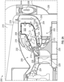
- FIGS. 3A-3B schematic illustrations of an integrated centrifugal compressor diffuser and high pressure turbine vane assembly 300 in accordance with an embodiment of the present disclosure are shown.
- the integrated centrifugal compressor diffuser and high pressure turbine vane assembly 300 may be part of a gas turbine engine, such as an aircraft engine.
- the aircraft engine in some configurations, may be a turboprop engine.
- the engine includes a compressor section, a combustion section, and a turbine section, such as shown and described above.
- a fan or the like may be rotationally driven by a shaft of the engine to generate thrust.
- FIG. 3A illustrates the integrated centrifugal compressor diffuser and high pressure turbine vane assembly 300 in isolation
- FIG. 3B illustrates the integrated centrifugal compressor diffuser and high pressure turbine vane assembly 300 as arranged within a portion of an engine case 302, forming a portion of a gas turbine engine 304.
- the integrated centrifugal compressor diffuser and high pressure turbine vane assembly 300 includes an impeller 306 that is part of a compressor section of the engine.
- the impeller 306 includes a set of impeller blades 308 that are coupled to a shaft 310 (e.g., engine shaft or spool or portion of engine shaft/spool).
- the impeller 306 is arranged to receive a core air flow 312 ( FIG. 3B ) from a core flow duct or the like, such as shown and described above.
- the impeller 306 rotates and the impeller blades 308 will cause the core air flow 312 to be compressed and directed into and through a set of first vanes 314 of a turbine section 316 of the engine 304.
- the first vanes 314 are hollow body structures (e.g., airfoils) that extend in a radial direction between an inner diameter platform 318 and an outer diameter platform 320. As shown, the inner diameter platform 318 of the first vanes 314 may be mounted to or surround an outlet of the impeller 306 such that the compressed air from the impeller 306 is directed into and through an internal vane passage 322 of the first vanes 314.
- hollow body structures e.g., airfoils
- the compressed core air flow 312 will pass through the internal vane passages 322 and enter a combustor cavity 324.
- the combustor cavity 324 is defined within the engine case 302 and contains a combustion chamber (see, e.g., FIGS. 2A-2B ).
- the compressed core air flow 312 will then enter the combustion chamber and mix with a fuel for combustion within the combustion chamber.
- the resulting hot core gas 326 will then be directed through an outlet of the combustion chamber and passed between a space 328 defined between adjacent first vanes 314.
- a shape and angle of the first vanes 314 will turn the hot core gas 326 in a direction of rotation of rotating components (e.g., disks) of the turbine section 316.
- the first vanes 314 are stationary components and the impeller 306 rotates relative to the first vanes 314, and is arranged radially inward from the first vanes 314.
- optional diffuser elements 330 e.g., fishtail or otherwise spreading/diffusing structures arranged at a downstream end of the first vanes 314 relative to a flow direction of the core air flow 312.
- the diffuser elements 330 may be installed and attached to the outer diameter platform 320 such that a continuous fluid path extends from an opening at the inner diameter platform 318, through the internal vane passage 322, and through the diffuser elements 330 before entering the combustor cavity 324.
- the outer diameter platform 320 may include diffuser element mounts 332 on an outer diameter surface thereof.
- the diffuser element mounts 332 may be structures or features configured to fixedly attach and mount the diffuser elements 330 to the outer diameter platform 320.
- the diffuser elements 330 are arranged with a gradually increasing cross-sectional area, in a direction of flow, such that the core flow passing through the diffuser elements 330 will expand and diffuse into the combustor cavity 324.
- the core air flow 312 will exit the impeller 306 and flow in a radial direction through the internal structure (internal vane passage 322) of the first vanes 314.
- the compressed core air flow 312 may provide back face (or internal) cooling to the first vanes 314.
- the process of cooling the first vanes 314 also adds energy to the core air flow 312 as it picks up heat from the hot material of the first vanes 314. That is, the downstream hot core gas 326, which is formed by combustion, will pass between exterior surfaces of the first vanes 314 and cause the material of the first vanes 314 to be heated.
- the internal, relatively cool core air flow 312 will pick up heat from this material and provide cooling to the first vanes 314. This added energy or heat, through heat pickup, can result in increased combustion efficiencies as the air introduced into the combustion chamber will be relatively warmer than if no such heat pick up occurred.
- examples of the present disclosure arrange at least the final compressor stages under (i.e., radially inward from) the combustor, thus shortening overall engine length and improving shaft dynamics and reducing weight significantly.
- this engine configurations described herein may achieve lower pressure ratios of the impeller, as compared to conventional systems. Such reduction can minimize the height (size) of the system and allows for the optimized gas path for the integrated compressor diffuser and first vane assembly.
- the centrifugal compressor diffuser vane (first vane) modifies a conventional high pressure turbine vane and leans or turns it into the direction of rotation of the rotating assembly.
- the internal structure of the first vane is formed as, at least, part of the diffuser, progressing to a larger area as it moves outward. Further diffusing may be achieved by adding the optional diffuser elements, as shown and described above.
- the cool flow from the compressor flows through the first vanes and surrounds the combustor.
- the hot combustion flow from the combustor flows between the first vanes and is turned in the direction of rotation of the rotating assembly and passed between the first vanes to enter the rest of the turbine section of the engine.
- the engine can be shortened by approximately 6". This allows for the use of a smaller compressor and the final stages of the compressor to have a lower radius with increased blade height.
- FIGS. 4A-4B schematic illustrations of a first vane 400 of a turbine section of a gas turbine engine in accordance with an embodiment of the present disclosure are shown.
- FIG. 4A is a side elevation view of the vane 400 and
- FIG. 4B is a cross-sectional view along the line B-B shown in FIG. 4A .
- the vane 400 defines an interior hollow body structure (airfoil body 402) with an internal vane path 404 (e.g., airfoil cavity).
- the internal vane path 404 is defined within the structure or body of the vane 400.
- the vane 400 includes a leading edge 406 and a trailing edge 408, with a pressure side wall 410 and a suction side wall 412 extending in a substantially axial direction (relative to engine axis) from the leading edge 404 to the trailing edge 406.
- the airfoil body 402 extends in a substantially radial direction (relative to engine axis) between an inner diameter platform 414 and an outer diameter platform 416.
- the internal vane path 404 is open and may be fluidly connected to an impeller, such as shown and described above.
- Incoming compressed air may enter the internal vane path 404 at the inner diameter end 418 and pass through the interior of the airfoil body 402, and thus provide cooling to the interior surfaces of the vane 400.
- the compressed air will then exit the internal vane path 404 at an outer diameter end 420 through an opening in the outer diameter platform 416, which may open into a combustor cavity, as shown and described above.
- the amount of airflow directed from the compressor section through the internal vane paths of the vanes of the present disclosure may be controlled or accommodated by adjusting features of the first vanes of the turbine sections of the engine.
- the vane 400 has an axial length 422, a radial height 424, and a circumferential width 426.
- Each of the vane dimensions 422, 424, 426 may be adjusted to accommodate the necessary airflow that is output from an upstream compressor section and operation of the downstream combustor.
- one or both of the axial length 422 and the circumferential width 426 may be increased to increase a total cross-sectional area of the internal vane path 404, and thus permit a larger volume of flow through the internal vane path 404.
- Consideration may also be given for the amount of cooling provided to the internal surfaces of the airfoil body 402 to ensure heat pickup and removal is achieved by a compressed air flow through the internal vane path 404.
- the dimensions of the of the internal vane path 404 may not be uniform in a flow direction.
- the internal vane path 404 may be part of a diffusion system, where the compressed air begins to expand and diffuse as it passes through the internal vane path 404.
- the axial length 422 and/or the circumferential width 426 may be narrower or smaller at the inner diameter end 418 than the respective axial length 422 and/or circumferential width 426 at the outer diameter end 420.
- the cross-sectional area of the internal vane path 404 may gradually increase from the inner diameter end 418 to the outer diameter end 420, and thus define or provide a diffusing structure directly within the first vane 400.
- Such narrow inner diameter and wider outer diameter is illustrated by dashed lines 428 shown in FIG. 4A .
- the material of the airfoil body 402 at the inner diameter end 418 may be thicker than the material at the outer diameter end 420.
- the structure of the airfoil body 402 may be narrowed as well, such that the distance between the leading edge 406 and the trailing edge 408 at the inner diameter end 418 is less than the distance between the leading edge 406 and the trailing edge 408 at the outer diameter end 420.
- embodiments described herein provide for gas turbine engines with modified arrangements that provide for improved cooling, improved efficiencies, and reduced axial length, among other benefits and features.
- cooling as noted above, compressor air is directed into the impeller of a centrifugal compressor and then into and through an internal passage of the turbine section (e.g., first vane).
- This direct cooling avoids the need for bleeding compressed air and routing it to cool the vanes from forward locations of the engine. That is, the compressed air, as it flows from the impeller to the combustion cavity around the combustor will also provide cooling to the turbine vanes.
- efficiencies because less (or no) bleed air is required, a smaller engine configuration may be possible.
- a reduced axial length of the engine core may be achieved by implementation of embodiments of the present disclosure. For example, by arranging a portion of the impeller of the compressor section to be axially aligned with a portion of the combustor section of the engine, but arranged radially inward from the combustor section, the total length of the engine may be reduced.
- the engine core may be reduced in length by up to 6 inches or more.
Landscapes
- Engineering & Computer Science (AREA)
- Mechanical Engineering (AREA)
- General Engineering & Computer Science (AREA)
- Chemical & Material Sciences (AREA)
- Combustion & Propulsion (AREA)
- Physics & Mathematics (AREA)
- Fluid Mechanics (AREA)
- Structures Of Non-Positive Displacement Pumps (AREA)
Abstract
Gas turbine engines (200) include a compressor section (202) having an impeller (212) configured to compress a core flow (208). A combustor section (204) having a combustor (220) is arranged downstream from the compressor section (202) along a path of the core flow (208). A turbine section (206) is arranged downstream from the combustor section (204) along the path of the core flow (208), with the turbine section (206) having a plurality of first vanes (214) arranged at an outlet of the combustor (220) and at least one first vane (214) of the plurality of first vanes (214) includes an internal vane path. The path of the core flow (208), in a flow direction, passes through the impeller (212) of the compressor section (202), the internal vane path internal to the first vane (214), the combustor (220), and then between external surfaces of the plurality of first vanes (214) to enter the turbine section (206).
Description
- The subject matter disclosed herein generally relates to components for turbine engines and, more particularly, to compressor, combustor, and turbine arrangements of turbine engines.
- Aircraft engines, such as gas turbine engines, typically include a fan to generate an airflow to be passed into an engine core and may direct a portion or a significant portion of the air around the engine core as a bypass flow. The engine core typically includes, in a direction from forward to aft, the fan, a compressor section, a combustor section, and a turbine section. Typically, the combustor must follow the compressor axially such that compressed air from the compressor section is directed into and mixed with fuel for combustion within one or more combustors of the combustor section. Due to the configurations and components of each section of the engine core, the axial length the engine cannot be shortened. Further, in operation, a relatively large compressor may be required to provide thorough cooling throughout the engine core. Bleed cooling flow may enter into the core gas path. Bleed air cooling of high-pressure turbine (HPT) vanes of the turbine section in current configurations necessarily reduces the amount of cool air available for cooling the combustor and for combustion. That is, a portion of the cooling air, taken from the compressor section, may be diverted around the combustor section to provide cooling to the vanes of the turbine section. The amount of air for cooling the vanes of the turbine section can be over 15% of core flow, which must be compensated for in the design process by increasing the core size.
- According to some examples, gas turbine engines are provided. The gas turbine engines include a compressor section having an impeller configured to compress a core flow, a combustor section having a combustor, with the combustor arranged downstream from the compressor section along a path of the core flow, and a turbine section arranged downstream from the combustor section along the path of the core flow, with the turbine section having a plurality of first vanes arranged at an outlet of the combustor, and at least one first vane of the plurality of first vanes includes an internal vane path. The path of the core flow, in a flow direction, passes through the impeller of the compressor section, the internal vane path internal to the first vane, the combustor, and then between external surfaces of the plurality of first vanes to enter the turbine section.
- In addition to one or more of the features described herein, or as an alternative, further examples of the gas turbine engine may include that at least a portion of the impeller is arranged radially inward from the combustor and at the same axial position as the combustor along an engine axis.
- In addition to one or more of the features described herein, or as an alternative, further examples of the gas turbine engine may include that the internal vane path has an increasing cross-sectional area extending in a direction of flow of the core flow.
- In addition to one or more of the features described herein, or as an alternative, further examples of the gas turbine engine may include that the combustor is arranged within a combustor cavity and the internal vane path fluidly connects the impeller with the combustor cavity.
- In addition to one or more of the features described herein, or as an alternative, further examples of the gas turbine engine may include that the combustor cavity comprises an inner diameter portion, wherein compressed air supplied through the internal vane path fills, at least, the inner diameter portion.
- In addition to one or more of the features described herein, or as an alternative, further examples of the gas turbine engine may include that the inner diameter portion is defined in a radial direction relative to an engine axis between an outer diameter surface of a part of the compressor section and an inner diameter surface of the combustor.
- In addition to one or more of the features described herein, or as an alternative, further examples of the gas turbine engine may include that the path of the core flow is in an axial forward direction through at least a portion of the compressor section and is turned in a radially outward direction by the impeller and flows radially outward through the internal vane path into a combustor cavity housing the combustor.
- In addition to one or more of the features described herein, or as an alternative, further examples of the gas turbine engine may include that the core flow path is turned to flow axially aft relative to the engine axis as it exits the internal vane path to surround the combustor and provide air thereto.
- In addition to one or more of the features described herein, or as an alternative, further examples of the gas turbine engine may include a diffuser element attached to an outer diameter platform of the first vane, wherein the internal vane path fluidly connects to the diffuser element, the diffuser element configured to diffuse and direct the core flow around the combustor.
- In addition to one or more of the features described herein, or as an alternative, further examples of the gas turbine engine may include that each first vane of the plurality of first vanes includes an internal vane path.
- In addition to one or more of the features described herein, or as an alternative, further examples of the gas turbine engine may include that the plurality of first vanes extend in a radial direction relative to an engine axis between an inner diameter platform and an outer diameter platform, wherein an outlet of the impeller is fluidly coupled to the inner diameter platform.
- In addition to one or more of the features described herein, or as an alternative, further examples of the gas turbine engine may include a diffusing element arranged at an outlet of the internal vane path.
- In addition to one or more of the features described herein, or as an alternative, further examples of the gas turbine engine may include that the outer diameter platform comprises a diffuser element mount, wherein the diffusing element is attached to the outer diameter platform at the diffuser element mount.
- In addition to one or more of the features described herein, or as an alternative, further examples of the gas turbine engine may include that each first vane of the plurality of first vanes includes an internal vane path and each first vane of the plurality of first vanes includes a respective diffusing element arranged at an outlet of the respective internal vane path.
- In addition to one or more of the features described herein, or as an alternative, further examples of the gas turbine engine may include that the internal vane path has a smaller cross-sectional area at the inner diameter platform than a cross-sectional area at the outer diameter platform.
- In addition to one or more of the features described herein, or as an alternative, further examples of the gas turbine engine may include that each first vane of the plurality of first vanes is angled in a direction of rotation of a rotating assembly of the gas turbine engine to direct the core flow as it exits the combustor in the direction of rotation of the rotating assembly.
- According to some examples, methods of operating gas turbine engines are provided. The gas turbine engines include a compressor section, a combustor section, and a turbine section, with at least a portion of the compressor section is arranged axially aligned with a combustor of the combustor section and radially inward from the combustor. The methods include compressing air of a core flow through an impeller of the compressor section, directing the compressed air through an internal vane path of at least one first vane of a plurality of first vanes of the turbine section as a radial direction flow, receiving the compressed air within the combustor to generate hot combustion gas, and directing the hot combustion gas between the plurality of first vanes and into the turbine section.
- In addition to one or more of the features described herein, or as an alternative, further examples of the methods may include diffusing the core flow through the internal vane path.
- In addition to one or more of the features described herein, or as an alternative, further examples of the methods may include diffusing the core flow through a diffuser element attached to an outlet of the internal vane path.
- In addition to one or more of the features described herein, or as an alternative, further examples of the methods may include turning a flow of the hot combustion gas as it passes between the plurality of first vanes in a direction of rotation of a rotating assembly of the gas turbine engine.
- The foregoing features and elements may be combined in various combinations without exclusivity, unless expressly indicated otherwise. These features and elements as well as the operation thereof will become more apparent in light of the following description and the accompanying drawings. It should be understood, however, that the following description and drawings are intended to be illustrative and explanatory in nature and non-limiting.
- The subject matter is particularly pointed out and distinctly claimed at the conclusion of the specification. The foregoing and other features, and advantages of the present disclosure are apparent from the following detailed description taken in conjunction with the accompanying drawings in which:
-
FIG. 1 is a schematic illustration of an aircraft engine in accordance with an embodiment of the present disclosure; -
FIG. 2A is a schematic illustration of a portion of a gas turbine engine in accordance with an embodiment of the present disclosure; -
FIG. 2B is a schematic illustration of an aircraft engine incorporating the structure shown inFIG. 2A ; -
FIG. 3A is a schematic illustration of an integrated centrifugal compressor diffuser and high pressure turbine vane assembly in accordance with an embodiment of the present disclosure; -
FIG. 3B is a schematic illustration of the integrated centrifugal compressor diffuser and high pressure turbine vane assembly as housed within a part of a gas turbine engine; -
FIG. 4A is a schematic illustration of a vane in accordance with an embodiment of the present disclosure; and -
FIG. 4B is a cross-sectional illustration of the vane ofFIG. 4A viewed along the line B-B ofFIG. 4A . -
FIG. 1 is a schematic illustration of anaircraft engine 100 that may incorporate embodiments of the present disclosure. Theaircraft engine 100 includes afan section 102, acombustion section 104, acompressor section 106, and aturbine section 108. Theaircraft engine 100 may be mounted to an aircraft fuselage and operationally driven to provide propulsive or motive force for flight of the aircraft. During operation, thecombustion section 104 will combust a fuel that is mixed with air. In this illustrative configuration of theaircraft engine 100, air may be compressed in thecompressor section 106 and the compressed air may be then directed into thecombustion section 104 for combustion with the fuel. The combusted fuel and air mixture will then be directed into and through theturbine section 108 to drive anengine shaft 110 or the like, which in turn will cause rotation of thefan section 102. Theengine shaft 110 may be formed of one or more shaft sections and/or spools. As will be appreciated by those of skill in the art. - The
engine shaft 110 is illustratively shown as connected to thefan section 102 of theaircraft engine 100. In some configurations, theengine shaft 110 may be directly coupled to a fan rotor or the like or may be connected thereto through a gear system, a clutch system, or the like. Theengine shaft 110 defines an engine axis, engine centerline, or central axis thereof. Thefan section 102,combustion section 104,compressor section 106, and theturbine section 108 may all be full circumferent or hoop structures arranged about the engine axis, with thefan section 102 at the forward end and theturbine section 108 at the aft end. The radially direction is an outward direction from the engine axis (or engine shaft 110) and the axial direction is parallel to the direction of the engine axis. - In operation, air may enter the
compressor section 106 at anair intake 112, which may be sourced from a bypass flow in a duct arranged radially outward from theair intake 112, as will be appreciated by those of skill in the art. The air is then compressed in thecompressor section 106, combusted with fuel in thecombustor section 104, and the hot gas output from thecombustor section 104 will pass through theturbine section 108 and then be exhausted out anexhaust exit 114. Theexhaust exit 114 may dump into a bypass duct of theaircraft engine 100. - It will be appreciated that the illustrative configuration of
FIG. 1 is merely illustrative and provided for explanatory purposes only. Various types of compressor configurations, turbine configurations, combustor configurations and the like may be implemented on engines without departing from the scope of the present disclosure. For example, although shown inFIG. 1 with the hot gas traveling in a forward direction (from theturbine section 108 to the exhaust exit 114), in other engine configurations, the hot gas may be directed through an impeller type compressor and then routed in an aftward flowing direction through a turbine. The hot gas may then be directed from the turbine into a bypass flow or the like and/or exhausted out an aft end of the engine system. As such, it will be appreciated that the specific illustrative configuration and arrangement of components shown inFIG. 1 is merely representative and not intended to be limiting on the disclosure herein. - Conventionally, the combustor of a gas turbine engine must follow the compressor section in an axial direction relative to the engine axis, and thus shortening of engine is difficult. Further, a large compressor is needed to provide thorough cooling to the engine, with a portion of the compressed air bled from the compressor for cooling of various engine components. This bleed air is thus removed from the potential total airflow for the combustor, and thus the size of the compressor may need to be increased to accommodate this bleed air extraction. Furthermore, because the bleed air must be routed through various mechanisms and then used for cooling, a portion of the bleed cooling flow may enter a core flow gas path. Bleed air cooling of the high-pressure turbine (HPT) vane in conventional engine configurations reduces the amount of air available for cooling the combustor and for combustion. The amount of air for cooling the HPT vane can be over 15% of core flow which must be compensated for in the design process by increasing the core size.
- In view of this, and other considerations, the engine configurations described herein integrate a compressor diffuser with a high-pressure turbine (HPT) blade assembly to reduce or eliminate bleed cooling flow into the gas path. Additionally, in accordance with some embodiments, the compressor air is used for back face cooling of the HPT vane (e.g., internal cooling flow). The process of cooling the HPT vane also adds energy in the form of heat to the compressed air before it enters the combustor, and such heat pickup can improve efficiency of the combustion process. In accordance with some embodiments, a centrifugal compressor is arranged such that at least the final compressor stage(s) is positioned to sit under (radially inward from) the combustor. In some embodiments, the entire centrifugal compressor (or the bladed portion thereof) may be arranged radially inward relative to the combustor. This axial alignment but radial stacking of at least a portion of the compressor section and the combustor results in a shortening of the overall engine length. Such configurations can improve shaft dynamics and/or reduce total engine weight.
- Additionally, advantageously, embodiments of the present disclosure allow the impeller to have a lower pressure ratio as compared to conventional impeller engines. Such reduced pressure ratio can minimize the height (size) of the impeller and allows for an optimal gas path for an integrated compressor diffuser and HPT vane, as shown and described herein. The centrifugal compressor diffuser vane may be configured as traditional HPT vane and leans it into a direction of rotation of the rotating assembly (e.g., turbine disk rotation). The internal structure of the HPT vane is formed as the diffuser, progressing to a larger area as it moves radially outward. Fishtails may be added at an outlet of the HPT vane to provide additional diffusion. The cool air flowing through the vanes cools the HPT vanes. After exiting the HPT vanes, the cool flow from the compressor through the HPT vanes will surround the combustor and enter a combustion chamber for combustion with fuel through, for example, impingement holes and/or effusion holes, as will be appreciated by those of skill in the art. The hot flow from the combustor is then directed between the vanes of the HPT and into the downstream parts of the turbine section to drive shafts or spools of the engine. In accordance with embodiments of the present disclosure, the disclosed arrangement and configuration of components can result in a shortened engine axial length. For example, and without limitation, the engines of the present disclosure can be shortened by approximately 6" as compared to a conventional in-line, axial arrangement. Advantageously, this allows for the use of a smaller compressor and the final stages of the compressor can have a lower radius with increased blade height.
- Referring now to
FIGS. 2A-2B , schematic illustrations of agas turbine engine 200 are shown. Thegas turbine engine 200 may be similar to that shown and described with respect toFIG. 1 , and is configured as an impeller-type engine. Thegas turbine engine 200 includes acompressor section 202, acombustion section 204, and aturbine section 206. As shown,core flow air 208 may be supplied into thecompressor 202 from acore flow duct 210. The relatively coolcore flow air 208 will enter animpeller 212 of thecompressor section 202. Theimpeller 212 will compress thecore flow air 208 and then direct thecore flow air 208 through afirst vane structure 214 of theturbine section 206 of theengine 200. Thecore flow air 208 will then be expanded or diffused through thefirst vane structure 214 and optional diffuser elements 216 (e.g., fishtail or otherwise spreading/diffusing structures) arranged at a downstream end of thefirst vane structure 214 relative to a core flow path. The diffusedcore flow air 208 will then direct directed to fill acombustor cavity 218 of thecombustor section 204. Acombustor 220 is arranged within thecombustor cavity 218 and defines acombustion chamber 222 therein. - Within the
combustion chamber 222, thecore flow air 208 is mixed with a fuel and ignited for combustion within thecombustion chamber 222. The fuel may be injected into thecombustion chamber 222 from one or more fuel nozzles, as will be appreciated by those of skill in the art. As the mixture ofcore flow air 208 and fuel are mixed and combusted, a hot core gas 224 (e.g., combusted air and fuel) will be directed through an exit or outlet of thecombustion chamber 222 and passed between vanes of thefirst vane structure 214. Thehot core gas 224 is turned by the vanes of thefirst vane structure 214 and drives rotation of afirst turbine 226 which includesblades 228 and may be operably coupled to ashaft 230. Thehot core gas 224 may then flow in an axially forward direction through the rest of theturbine section 206, as will be appreciated by those of skill in the art. Thehot core gas 224 may then be turned aftward and mixed or injected into a bypass flow of thegas turbine engine 200, as will be appreciated by those of skill in the art. In some engine configurations, the bypass flow may be through a duct that is arranged radially outward from thecore flow duct 210. - As shown, the
combustor cavity 218 is defined, in part, between an outer diametercombustor cavity case 232 and an inner diametercombustor cavity case 234. The inner diametercombustor cavity case 234 may also define a portion of the input path that connects thecore flow duct 210 to theimpeller 212 of thecompressor section 202. With this configuration, aninner diameter portion 218a of thecombustor cavity 218 is defined between an inner diameter surface of thecombustor 220 and an outer diameter surface of the inner diametercombustor cavity case 234. An outer diameter surface of theimpeller 212, in accordance with some embodiments, may also define a surface of theinner diameter portion 218a of thecombustor cavity 218. The inner diametercombustor cavity case 234 includes an inner diameter side that is a part of thecore flow duct 210 and/or a part of theimpeller 212 and an outer diameter side that is part of thecombustor cavity 218. The core flowduct 210 is defined, in part and proximate thecombustion section 204, by anengine case 236 and the inner diametercombustor cavity case 234. -
FIG. 2B illustrates thegas turbine engine 200 having the structure illustrated inFIG. 2A . Thegas turbine engine 200 includes afan section 238, a combustion section 240, a lowpressure compressor section 242, a highpressure compressor section 244, and aturbine section 246 arranged about anengine shaft 248. In operation, fan driven air (e.g., through a bypass duct or the like) will enter the lowpressure compressor section 242 at anair intake 250, and flow through the system, as described with respect toFIG. 2A . The hot combusted gas will then exit through anexhaust outlet 252, which may dump into the bypass duct at a location downstream from theair intake 250 along the bypass duct. - Referring now to
FIGS. 3A-3B , schematic illustrations of an integrated centrifugal compressor diffuser and high pressureturbine vane assembly 300 in accordance with an embodiment of the present disclosure are shown. The integrated centrifugal compressor diffuser and high pressureturbine vane assembly 300 may be part of a gas turbine engine, such as an aircraft engine. The aircraft engine, in some configurations, may be a turboprop engine. The engine includes a compressor section, a combustion section, and a turbine section, such as shown and described above. A fan or the like may be rotationally driven by a shaft of the engine to generate thrust.FIG. 3A illustrates the integrated centrifugal compressor diffuser and high pressureturbine vane assembly 300 in isolation, andFIG. 3B illustrates the integrated centrifugal compressor diffuser and high pressureturbine vane assembly 300 as arranged within a portion of anengine case 302, forming a portion of agas turbine engine 304. - As shown in
FIGS. 3A-3B , the integrated centrifugal compressor diffuser and high pressureturbine vane assembly 300 includes animpeller 306 that is part of a compressor section of the engine. Theimpeller 306 includes a set ofimpeller blades 308 that are coupled to a shaft 310 (e.g., engine shaft or spool or portion of engine shaft/spool). Theimpeller 306 is arranged to receive a core air flow 312 (FIG. 3B ) from a core flow duct or the like, such as shown and described above. Theimpeller 306 rotates and theimpeller blades 308 will cause thecore air flow 312 to be compressed and directed into and through a set offirst vanes 314 of aturbine section 316 of theengine 304. Thefirst vanes 314 are hollow body structures (e.g., airfoils) that extend in a radial direction between aninner diameter platform 318 and anouter diameter platform 320. As shown, theinner diameter platform 318 of thefirst vanes 314 may be mounted to or surround an outlet of theimpeller 306 such that the compressed air from theimpeller 306 is directed into and through aninternal vane passage 322 of thefirst vanes 314. - The compressed
core air flow 312 will pass through theinternal vane passages 322 and enter acombustor cavity 324. Thecombustor cavity 324 is defined within theengine case 302 and contains a combustion chamber (see, e.g.,FIGS. 2A-2B ). The compressedcore air flow 312 will then enter the combustion chamber and mix with a fuel for combustion within the combustion chamber. The resultinghot core gas 326 will then be directed through an outlet of the combustion chamber and passed between aspace 328 defined between adjacentfirst vanes 314. As thehot core gas 326 passes through thespace 328, a shape and angle of thefirst vanes 314 will turn thehot core gas 326 in a direction of rotation of rotating components (e.g., disks) of theturbine section 316. It is noted that thefirst vanes 314 are stationary components and theimpeller 306 rotates relative to thefirst vanes 314, and is arranged radially inward from thefirst vanes 314. - In some configurations, and as shown in
FIGS. 3A-3B , optional diffuser elements 330 (e.g., fishtail or otherwise spreading/diffusing structures) arranged at a downstream end of thefirst vanes 314 relative to a flow direction of thecore air flow 312. Thediffuser elements 330 may be installed and attached to theouter diameter platform 320 such that a continuous fluid path extends from an opening at theinner diameter platform 318, through theinternal vane passage 322, and through thediffuser elements 330 before entering thecombustor cavity 324. In the non-limiting illustrative embodiment ofFIGS. 3A-3B , theouter diameter platform 320 may include diffuser element mounts 332 on an outer diameter surface thereof. The diffuser element mounts 332 may be structures or features configured to fixedly attach and mount thediffuser elements 330 to theouter diameter platform 320. Thediffuser elements 330 are arranged with a gradually increasing cross-sectional area, in a direction of flow, such that the core flow passing through thediffuser elements 330 will expand and diffuse into thecombustor cavity 324. - In operation, the
core air flow 312 will exit theimpeller 306 and flow in a radial direction through the internal structure (internal vane passage 322) of thefirst vanes 314. As such, the compressedcore air flow 312 may provide back face (or internal) cooling to thefirst vanes 314. The process of cooling thefirst vanes 314 also adds energy to thecore air flow 312 as it picks up heat from the hot material of thefirst vanes 314. That is, the downstreamhot core gas 326, which is formed by combustion, will pass between exterior surfaces of thefirst vanes 314 and cause the material of thefirst vanes 314 to be heated. The internal, relatively coolcore air flow 312 will pick up heat from this material and provide cooling to thefirst vanes 314. This added energy or heat, through heat pickup, can result in increased combustion efficiencies as the air introduced into the combustion chamber will be relatively warmer than if no such heat pick up occurred. - In addition to providing direct first vane cooling, examples of the present disclosure arrange at least the final compressor stages under (i.e., radially inward from) the combustor, thus shortening overall engine length and improving shaft dynamics and reducing weight significantly. As noted above, this engine configurations described herein may achieve lower pressure ratios of the impeller, as compared to conventional systems. Such reduction can minimize the height (size) of the system and allows for the optimized gas path for the integrated compressor diffuser and first vane assembly. Furthermore, as noted, the centrifugal compressor diffuser vane (first vane) modifies a conventional high pressure turbine vane and leans or turns it into the direction of rotation of the rotating assembly. The internal structure of the first vane is formed as, at least, part of the diffuser, progressing to a larger area as it moves outward. Further diffusing may be achieved by adding the optional diffuser elements, as shown and described above. The cool flow from the compressor flows through the first vanes and surrounds the combustor. The hot combustion flow from the combustor flows between the first vanes and is turned in the direction of rotation of the rotating assembly and passed between the first vanes to enter the rest of the turbine section of the engine. Furthermore, as noted, the engine can be shortened by approximately 6". This allows for the use of a smaller compressor and the final stages of the compressor to have a lower radius with increased blade height.
- Referring now to
FIGS. 4A-4B , schematic illustrations of afirst vane 400 of a turbine section of a gas turbine engine in accordance with an embodiment of the present disclosure are shown.FIG. 4A is a side elevation view of thevane 400 andFIG. 4B is a cross-sectional view along the line B-B shown inFIG. 4A . Thevane 400 defines an interior hollow body structure (airfoil body 402) with an internal vane path 404 (e.g., airfoil cavity). Theinternal vane path 404 is defined within the structure or body of thevane 400. With reference to bothFIGS. 4A and4B , thevane 400 includes aleading edge 406 and a trailingedge 408, with apressure side wall 410 and asuction side wall 412 extending in a substantially axial direction (relative to engine axis) from theleading edge 404 to the trailingedge 406. - As shown in
FIG. 4A , theairfoil body 402 extends in a substantially radial direction (relative to engine axis) between aninner diameter platform 414 and anouter diameter platform 416. At aninner diameter end 418 of theairfoil body 402, theinternal vane path 404 is open and may be fluidly connected to an impeller, such as shown and described above. Incoming compressed air may enter theinternal vane path 404 at theinner diameter end 418 and pass through the interior of theairfoil body 402, and thus provide cooling to the interior surfaces of thevane 400. The compressed air will then exit theinternal vane path 404 at anouter diameter end 420 through an opening in theouter diameter platform 416, which may open into a combustor cavity, as shown and described above. - As noted above, the amount of airflow directed from the compressor section through the internal vane paths of the vanes of the present disclosure may be controlled or accommodated by adjusting features of the first vanes of the turbine sections of the engine. For example, the
vane 400 has anaxial length 422, aradial height 424, and acircumferential width 426. Each of thevane dimensions axial length 422 and thecircumferential width 426 may be increased to increase a total cross-sectional area of theinternal vane path 404, and thus permit a larger volume of flow through theinternal vane path 404. Consideration may also be given for the amount of cooling provided to the internal surfaces of theairfoil body 402 to ensure heat pickup and removal is achieved by a compressed air flow through theinternal vane path 404. - Furthermore, in accordance with some embodiments, the dimensions of the of the
internal vane path 404 may not be uniform in a flow direction. For example, as noted above, theinternal vane path 404 may be part of a diffusion system, where the compressed air begins to expand and diffuse as it passes through theinternal vane path 404. Accordingly, in some embodiments, theaxial length 422 and/or thecircumferential width 426 may be narrower or smaller at theinner diameter end 418 than the respectiveaxial length 422 and/orcircumferential width 426 at theouter diameter end 420. Stated another way, the cross-sectional area of theinternal vane path 404 may gradually increase from theinner diameter end 418 to theouter diameter end 420, and thus define or provide a diffusing structure directly within thefirst vane 400. Such narrow inner diameter and wider outer diameter is illustrated by dashedlines 428 shown inFIG. 4A . In some such configurations, the material of theairfoil body 402 at theinner diameter end 418 may be thicker than the material at theouter diameter end 420. In other configurations, the structure of theairfoil body 402 may be narrowed as well, such that the distance between theleading edge 406 and the trailingedge 408 at theinner diameter end 418 is less than the distance between theleading edge 406 and the trailingedge 408 at theouter diameter end 420. - Advantageously, embodiments described herein provide for gas turbine engines with modified arrangements that provide for improved cooling, improved efficiencies, and reduced axial length, among other benefits and features. With respect to cooling, as noted above, compressor air is directed into the impeller of a centrifugal compressor and then into and through an internal passage of the turbine section (e.g., first vane). This direct cooling avoids the need for bleeding compressed air and routing it to cool the vanes from forward locations of the engine. That is, the compressed air, as it flows from the impeller to the combustion cavity around the combustor will also provide cooling to the turbine vanes. With respect to efficiencies, because less (or no) bleed air is required, a smaller engine configuration may be possible. For example, in a conventional, axially arranged engine, over 15% of core flow may be extracted from the compressor section and routed around the combustor section to supply cooling air to the turbine vanes. However, advantageously, by directly routing the entire core flow through the interior of the turbine vanes, cooling is applied directly thereto without the need for any bleed air for cooling. Accordingly, up to 15% or greater efficiency in terms of bleed air may be achieved.
- As noted, a reduced axial length of the engine core may be achieved by implementation of embodiments of the present disclosure. For example, by arranging a portion of the impeller of the compressor section to be axially aligned with a portion of the combustor section of the engine, but arranged radially inward from the combustor section, the total length of the engine may be reduced. For example, and without limitation, the engine core may be reduced in length by up to 6 inches or more.
- The use of the terms "a", "an", "the", and similar references in the context of description (especially in the context of the following claims) are to be construed to cover both the singular and the plural, unless otherwise indicated herein or specifically contradicted by context. The modifier "about" used in connection with a quantity is inclusive of the stated value and has the meaning dictated by the context (e.g., it includes the degree of error associated with measurement of the particular quantity). All ranges disclosed herein are inclusive of the endpoints, and the endpoints are independently combinable with each other. It should be appreciated that relative positional terms such as "forward," "aft," "upper," "lower," "above," "below," and the like are with reference to normal operational attitude and should not be considered otherwise limiting.
- While the present disclosure has been described in detail in connection with only a limited number of embodiments, it should be readily understood that the present disclosure is not limited to such disclosed embodiments. Rather, the present disclosure can be modified to incorporate any number of variations, alterations, substitutions, combinations, sub-combinations, or equivalent arrangements not heretofore described, but which are commensurate with the scope of the present disclosure. Additionally, while various embodiments of the present disclosure have been described, it is to be understood that aspects of the present disclosure may include only some of the described embodiments.
- Accordingly, the present disclosure is not to be seen as limited by the foregoing description, but is only limited by the scope of the appended claims.
Claims (15)
- A gas turbine engine (100; 200) comprising:a compressor section (106; 202; 242, 244) comprising an impeller (212; 306) configured to compress a core flow (208; 312);a combustor section (104; 204; 244) comprising a combustor (220), wherein the combustor (220) is arranged downstream from the compressor section (106; 202; 242, 244) along a path of the core flow (208; 312); anda turbine section (108; 206; 246; 316) arranged downstream from the combustor section (104; 204; 244) along the path of the core flow (208; 312), wherein the turbine section (104; 204; 244) comprises a plurality of first vanes (214; 314; 400) arranged at an outlet of the combustor (220), wherein at least one first vane (214; 314; 400) of the plurality of first vanes (214; 314; 400) comprises an internal vane path (322; 404);wherein the path of the core flow (208; 312), in a flow direction, passes through the impeller (212; 306) of the compressor section (106; 202; 242, 244), the internal vane path (322; 404) internal to the first vane (214; 314; 400), the combustor (220), and then between external surfaces of the plurality of first vanes (214; 314; 400) to enter the turbine section (108; 206; 246; 316).
- The gas turbine engine of claim 1, wherein at least a portion of the impeller (212; 306) is arranged radially inward from the combustor (220) and at the same axial position as the combustor (220) along an engine axis.
- The gas turbine engine of claim 1 or 2, wherein the internal vane path (322; 404) has an increasing cross-sectional area extending in a direction of flow of the core flow (208; 312).
- The gas turbine engine of any preceding claim, wherein the combustor (220) is arranged within a combustor cavity (218; 324) and the internal vane path (322; 404) fluidly connects the impeller (212; 306) with the combustor cavity (218; 324).
- The gas turbine engine of claim 4, wherein the combustor cavity (218; 324) comprises an inner diameter portion (218a), wherein compressed air (208; 312) supplied through the internal vane path (322; 404) fills, at least, the inner diameter portion (218a), optionally wherein the inner diameter portion (218a) is defined in a radial direction relative to an engine axis between an outer diameter surface of a part of the compressor section (106; 202; 242; 244) and an inner diameter surface of the combustor (220).
- The gas turbine engine of any preceding claim, wherein the path of the core flow (208; 312) is in an axial forward direction through at least a portion of the compressor section (106; 202; 242; 244) and is turned in a radially outward direction by the impeller (212; 306) and flows radially outward through the internal vane path (322; 404) into a combustor cavity (218; 324) housing the combustor (220).
- The gas turbine engine of claim 6, wherein the core flow path (208; 312) is turned to flow axially aft relative to the engine axis as it exits the internal vane path (322; 404) to surround the combustor (220) and provide air thereto, optionally wherein the gas turbine engine further comprises a diffuser element (216; 330) attached to an outer diameter platform (320; 416) of the first vane (214; 314; 400), wherein the internal vane path (322; 404) fluidly connects to the diffuser element (216; 330), the diffuser element (216; 330) configured to diffuse and direct the core flow (208; 312) around the combustor (220).
- The gas turbine engine of any preceding claim, wherein each first vane (214; 314; 400) of the plurality of first vanes (214; 314; 400) includes an internal vane path (322; 404).
- The gas turbine engine of any preceding claim, wherein the plurality of first vanes (214; 314; 400) extend in a radial direction relative to an engine axis between an inner diameter platform (318; 414) and an outer diameter platform (320; 416), wherein an outlet of the impeller (212; 306) is fluidly coupled to the inner diameter platform (318; 414).
- The gas turbine engine of claim 9, further comprising a diffusing element (216; 330) arranged at an outlet of the internal vane path (322; 404), optionally wherein the outer diameter platform (320; 416) comprises a diffuser element mount (332), wherein the diffusing element (216; 330) is attached to the outer diameter platform (320; 416) at the diffuser element mount (332), further optionally wherein each first vane (214; 314; 400) of the plurality of first vanes (214; 314; 400) includes an internal vane path (322; 404) and each first vane (214; 314; 400) of the plurality of first vanes (214; 314; 400) includes a respective diffusing element (216; 330) arranged at an outlet of the respective internal vane path (322; 404).
- The gas turbine engine of claim 9 or 10 , wherein the internal vane path (322; 404) has a smaller cross-sectional area at the inner diameter platform (318; 414) than a cross-sectional area at the outer diameter platform (320; 416).
- The gas turbine engine of any preceding claim, wherein each first vane (214; 314; 400) of the plurality of first vanes (214; 314; 400) is angled in a direction of rotation of a rotating assembly of the gas turbine engine (100; 200) to direct the core flow (208; 312) as it exits the combustor (220) in the direction of rotation of the rotating assembly.
- A method of operating a gas turbine engine (100; 200), the gas turbine engine (100; 200) comprising a compressor section (106; 202; 242, 244), a combustor section (104; 204; 244), and a turbine section (108; 206; 246; 316), wherein at least a portion of the compressor section (106; 202; 242, 244) is arranged axially aligned with a combustor (220) of the combustor section (104; 204; 244) and radially inward from the combustor (220), the method comprising:compressing air (208; 312) of a core flow through an impeller (212; 306) of the compressor section (106; 202; 242, 244);directing the compressed air (208; 312) through an internal vane path (322; 404) of at least one first vane (214; 314; 400) of a plurality of first vanes (214; 313; 400) of the turbine section (108; 206; 246; 316) as a radial direction flow;receiving the compressed air (208; 312) within the combustor (220) to generate hot combustion gas (224; 326); anddirecting the hot combustion gas (224; 326) between the plurality of first vanes (214; 314; 400) and into the turbine section (108; 206; 246; 316).
- The method of claim 13, further comprising: diffusing the core flow (208; 313) through the internal vane path (322; 404); and/or diffusing the core flow (208; 313) through a diffuser element (216; 330) attached to an outlet of the internal vane path (322; 404).
- The method of claim 13 or 14, further comprising turning a flow of the hot combustion gas (224; 326) as it passes between the plurality of first vanes (214; 314; 400) in a direction of rotation of a rotating assembly of the gas turbine engine (100; 200).
Applications Claiming Priority (1)
| Application Number | Priority Date | Filing Date | Title |
|---|---|---|---|
| US18/541,606 US12140048B1 (en) | 2023-12-15 | 2023-12-15 | Integrated centrifugal compressor diffuser and high pressure turbine vane assembly |
Publications (1)
| Publication Number | Publication Date |
|---|---|
| EP4571053A1 true EP4571053A1 (en) | 2025-06-18 |
Family
ID=93381511
Family Applications (1)
| Application Number | Title | Priority Date | Filing Date |
|---|---|---|---|
| EP24218867.0A Pending EP4571053A1 (en) | 2023-12-15 | 2024-12-10 | Integrated centrigual compressor diffuser and high pressure turbine vane assembly |
Country Status (2)
| Country | Link |
|---|---|
| US (1) | US12140048B1 (en) |
| EP (1) | EP4571053A1 (en) |
Citations (5)
| Publication number | Priority date | Publication date | Assignee | Title |
|---|---|---|---|---|
| US2611241A (en) * | 1946-03-19 | 1952-09-23 | Packard Motor Car Co | Power plant comprising a toroidal combustion chamber and an axial flow gas turbine with blade cooling passages therein forming a centrifugal air compressor |
| US3269120A (en) * | 1964-07-16 | 1966-08-30 | Curtiss Wright Corp | Gas turbine engine with compressor and turbine passages in a single rotor element |
| US5341636A (en) * | 1984-10-10 | 1994-08-30 | Paul Marius A | Gas turbine engine operating method |
| US6647707B2 (en) * | 2000-09-05 | 2003-11-18 | Sudarshan Paul Dev | Nested core gas turbine engine |
| US20040025490A1 (en) * | 2002-04-15 | 2004-02-12 | Paul Marius A. | Integrated bypass turbojet engines for air craft and other vehicles |
Family Cites Families (11)
| Publication number | Priority date | Publication date | Assignee | Title |
|---|---|---|---|---|
| FR2656657A1 (en) | 1989-12-28 | 1991-07-05 | Snecma | AIR COOLED TURBOMACHINE AND METHOD FOR COOLING THE SAME. |
| US6279322B1 (en) * | 1999-09-07 | 2001-08-28 | General Electric Company | Deswirler system for centrifugal compressor |
| DE602004031986D1 (en) * | 2004-12-01 | 2011-05-05 | United Technologies Corp | BLOWER TURBINE ROTOR ASSEMBLY FOR A TOP TURBINE ENGINE |
| US20160115971A1 (en) * | 2014-10-27 | 2016-04-28 | Pratt & Whitney Canada Corp. | Diffuser pipe with splitter vane |
| US10344623B2 (en) * | 2014-12-16 | 2019-07-09 | United Technologies Corporation | Pre-diffuser strut for gas turbine engine |
| US10718222B2 (en) * | 2017-03-27 | 2020-07-21 | General Electric Company | Diffuser-deswirler for a gas turbine engine |
| JP7011502B2 (en) * | 2018-03-20 | 2022-01-26 | 本田技研工業株式会社 | Centrifugal compressor pipe diffuser |
| US11098730B2 (en) * | 2019-04-12 | 2021-08-24 | Rolls-Royce Corporation | Deswirler assembly for a centrifugal compressor |
| US11286951B2 (en) * | 2019-05-21 | 2022-03-29 | Pratt & Whitney Canada Corp. | Diffuser pipe with exit scallops |
| US20200378303A1 (en) * | 2019-06-03 | 2020-12-03 | Pratt & Whitney Canada Corp. | Diffuser pipe exit flare |
| US11441516B2 (en) * | 2020-07-14 | 2022-09-13 | Rolls-Royce North American Technologies Inc. | Centrifugal compressor assembly for a gas turbine engine with deswirler having sealing features |
-
2023
- 2023-12-15 US US18/541,606 patent/US12140048B1/en active Active
-
2024
- 2024-12-10 EP EP24218867.0A patent/EP4571053A1/en active Pending
Patent Citations (5)
| Publication number | Priority date | Publication date | Assignee | Title |
|---|---|---|---|---|
| US2611241A (en) * | 1946-03-19 | 1952-09-23 | Packard Motor Car Co | Power plant comprising a toroidal combustion chamber and an axial flow gas turbine with blade cooling passages therein forming a centrifugal air compressor |
| US3269120A (en) * | 1964-07-16 | 1966-08-30 | Curtiss Wright Corp | Gas turbine engine with compressor and turbine passages in a single rotor element |
| US5341636A (en) * | 1984-10-10 | 1994-08-30 | Paul Marius A | Gas turbine engine operating method |
| US6647707B2 (en) * | 2000-09-05 | 2003-11-18 | Sudarshan Paul Dev | Nested core gas turbine engine |
| US20040025490A1 (en) * | 2002-04-15 | 2004-02-12 | Paul Marius A. | Integrated bypass turbojet engines for air craft and other vehicles |
Also Published As
| Publication number | Publication date |
|---|---|
| US12140048B1 (en) | 2024-11-12 |
Similar Documents
| Publication | Publication Date | Title |
|---|---|---|
| CA3014977C (en) | Air delivery system for a gas turbine engine | |
| EP2584142B1 (en) | Gas turbine engine cooling systems having hub-bleed impellers | |
| CN114718656B (en) | System for controlling blade clearance in a gas turbine engine | |
| CN110005530B (en) | Compressor cooling in a gas turbine engine | |
| EP3121410A1 (en) | Cooling system for a turbine engine | |
| CN107084003B (en) | Turbine airfoil for a gas turbine engine and method of manufacturing the same | |
| CN106468181A (en) | Jet-impingement nozzle for gas-turbine unit | |
| JP2017040264A (en) | Compressor bleed auxiliary turbine | |
| JP2017040263A (en) | Mixed flow turbo core | |
| US10221773B2 (en) | Bleed valve assembly for a gas turbine engine | |
| US20180100441A1 (en) | Bleed valve assembly for a gas turbine engine | |
| EP3458685A1 (en) | Gas compressor and method of cooling a rotatable member | |
| US12072100B1 (en) | Combustor for a gas turbine engine | |
| US20180328177A1 (en) | Gas turbine engine with a cooled compressor | |
| EP2551458A2 (en) | Blade Cooling and Sealing System | |
| EP3392458A1 (en) | Turbine with upstream facing tangential onboard injector for | |
| US11732592B2 (en) | Method of cooling a turbine blade | |
| US20160312654A1 (en) | Turbine airfoil cooling | |
| US12140048B1 (en) | Integrated centrifugal compressor diffuser and high pressure turbine vane assembly | |
| EP3524795B1 (en) | Axial compressor with inter-stage centrifugal compressor | |
| EP4230841A1 (en) | Compressor-turbine rotating assembly with integral cooling circuit(s) | |
| CA3258849A1 (en) | Integrated centrifugal compressor diffuser and high pressure turbine vane assembly | |
| US12338748B1 (en) | Integrated axial compressor diffuser and high pressure turbine vane assembly | |
| EP4431702A1 (en) | Steam cooling turbine stator vane array | |
| US20250043726A1 (en) | Containment ring cavity pressurization system |
Legal Events
| Date | Code | Title | Description |
|---|---|---|---|
| PUAI | Public reference made under article 153(3) epc to a published international application that has entered the european phase |
Free format text: ORIGINAL CODE: 0009012 |
|
| STAA | Information on the status of an ep patent application or granted ep patent |
Free format text: STATUS: THE APPLICATION HAS BEEN PUBLISHED |
|
| AK | Designated contracting states |
Kind code of ref document: A1 Designated state(s): AL AT BE BG CH CY CZ DE DK EE ES FI FR GB GR HR HU IE IS IT LI LT LU LV MC ME MK MT NL NO PL PT RO RS SE SI SK SM TR |
|
| STAA | Information on the status of an ep patent application or granted ep patent |
Free format text: STATUS: REQUEST FOR EXAMINATION WAS MADE |
|
| 17P | Request for examination filed |
Effective date: 20251127 |